2016final exam see3433-nov - universiti teknologi malaysia
TRANSCRIPT
UNIVERSITI TEKNOLOGI MALAYSIA PEPERIKSAAN AKHIR
SEMESTER 1 SESI 2016/2017
KOD MATAPELAJARAN : SEE 3433
MATA PELAJARAN : MESIN ELEKTRIK
PENSYARAH : ABD JAAFAR SHAFIE (JB) NIK DIN MUHAMAD (KL)
KURSUS : SEE
SEKSYEN :
MASA : 2 JAM 30 MINIT
TARIKH :
ARAHAN KEPADA CALON
:
JAWAB EMPAT (4) SOALAN SAHAJA. SEMUA PENGIRAAN HENDAKLAH DITUNJUKKAN DENGAN JELAS.
KERTAS SOALAN INI TERDIRI DARIPADA 9 (SEMBILAN) MUKA SURAT SAHAJA
SULIT
-2- SKEE4633/SEE3433
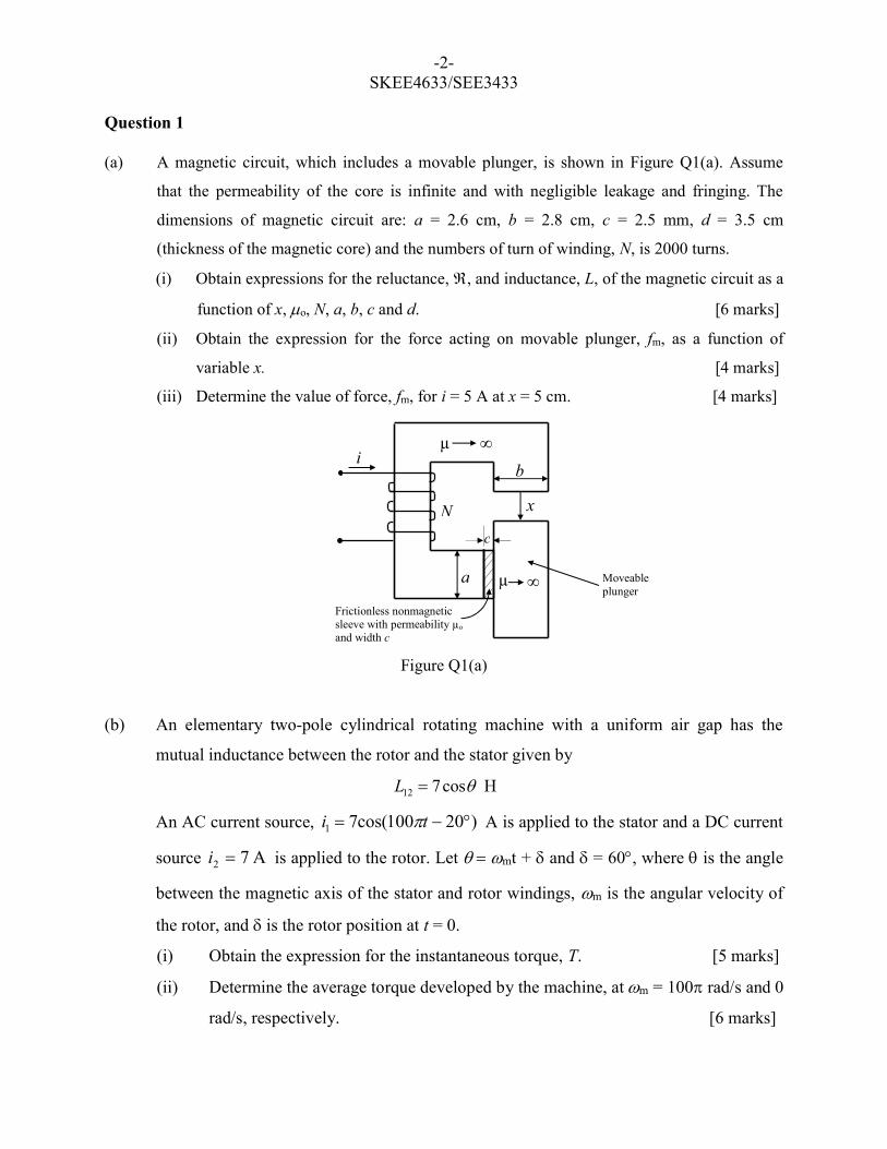
Question 1 (a) A magnetic circuit, which includes a movable plunger, is shown in Figure Q1(a). Assume
that the permeability of the core is infinite and with negligible leakage and fringing. The
dimensions of magnetic circuit are: a = 2.6 cm, b = 2.8 cm, c = 2.5 mm, d = 3.5 cm
(thickness of the magnetic core) and the numbers of turn of winding, N, is 2000 turns.
(i) Obtain expressions for the reluctance, , and inductance, L, of the magnetic circuit as a
function of x, o, N, a, b, c and d. [6 marks]
(ii) Obtain the expression for the force acting on movable plunger, fm, as a function of
variable x. [4 marks]
(iii) Determine the value of force, fm, for i = 5 A at x = 5 cm. [4 marks]
Figure Q1(a)
(b) An elementary two-pole cylindrical rotating machine with a uniform air gap has the
mutual inductance between the rotor and the stator given by
cos712 L H
An AC current source, )20100cos(71 ti A is applied to the stator and a DC current
source A72 i is applied to the rotor. Let mt + and = 60, where is the angle
between the magnetic axis of the stator and rotor windings, m is the angular velocity of
the rotor, and is the rotor position at t = 0.
(i) Obtain the expression for the instantaneous torque, T. [5 marks]
(ii) Determine the average torque developed by the machine, at m = 100 rad/s and 0
rad/s, respectively. [6 marks]
Moveable plunger
µ ∞
µ b
a
x N
i
Frictionless nonmagnetic sleeve with permeability µo
and width c
c
-3- SKEE4633/SEE3433
Question 2
(a) Starting from the equation for the induced voltage in a single conductor with a length of l,
moving linearly at a constant speed of v, in a magnetic field density of B, show that the total
induced voltage in the armature winding of a DC generator in volt can be given by
E a Np
am
where N is total number of turns, p is number of poles, a is number of parallel paths, is
flux per pole and m is mechanical speed. [6 marks]
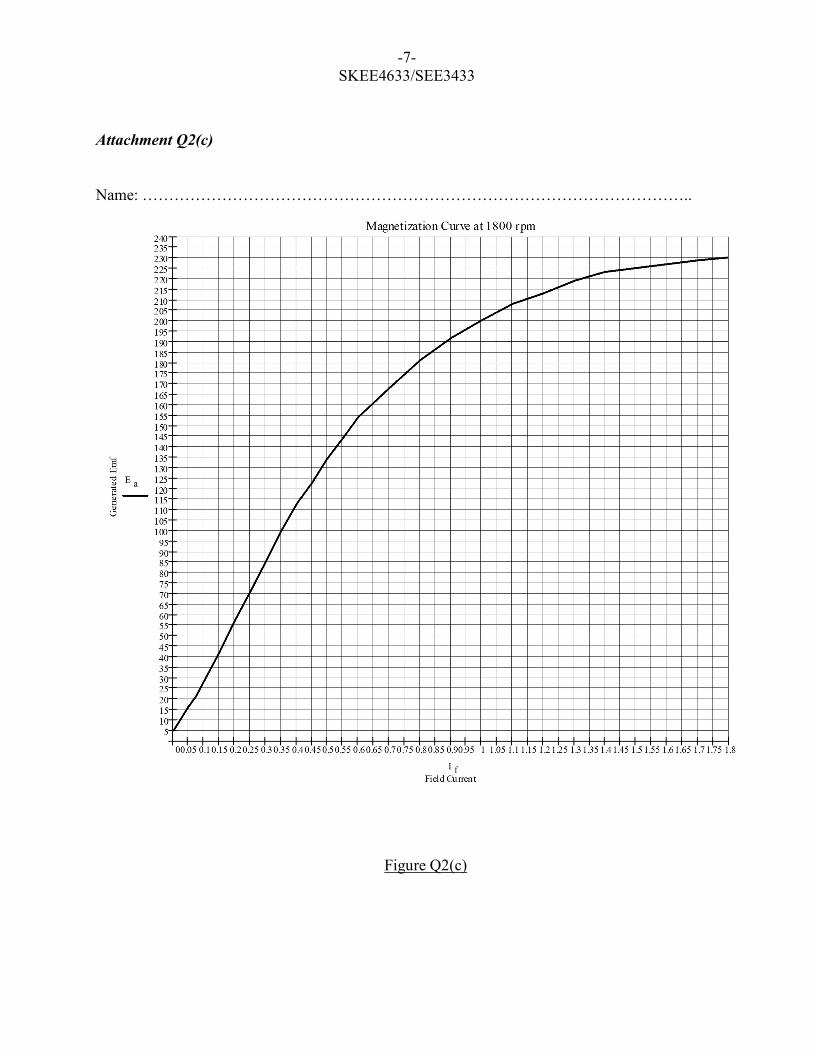
(b) A 21 kW, 210 V, 1800 rpm, Ra = 0.1 DC machine operated as shunt generator has a
magnetization characteristic at 1800 rpm as shown in Figure 2(c) in Attachment Q2(c). The
shunt field winding resistance Rfw = 80 and the number of turns Nf = 1000 turns per pole.
The effect of armature reaction at full-load, If(AR), is 0.10 A.
(i) Determine the maximum generated voltage. [4 marks]
(ii) The machine is operated as a shunt generator at 1800 rpm and the no-load terminal
voltage is adjusted to 210 V. Determine the full load terminal voltage with and
without armature reaction effect. [5 marks]
(iii) The no-load terminal voltage is the same as in (ii) but the load is reduced to 75% of
the full load. Determine the terminal voltage with and without armature reaction
effect. Assume the effect of armature reaction is proportional to Ia. [5 marks]
(iv) Determine the maximum value of the armature current that the generator can supply
and the corresponding value of the terminal voltage. Assume that If(AR) = 0.125 A at
the maximum armature current. [5 marks]
You must submit Attachment Q2(c) with your answer booklet
-4- SKEE4633/SEE3433
Question 3
(a) Explain the necessity for the use of starter with a DC motor. Explain how the starting
methods can be achieved. [6 marks]
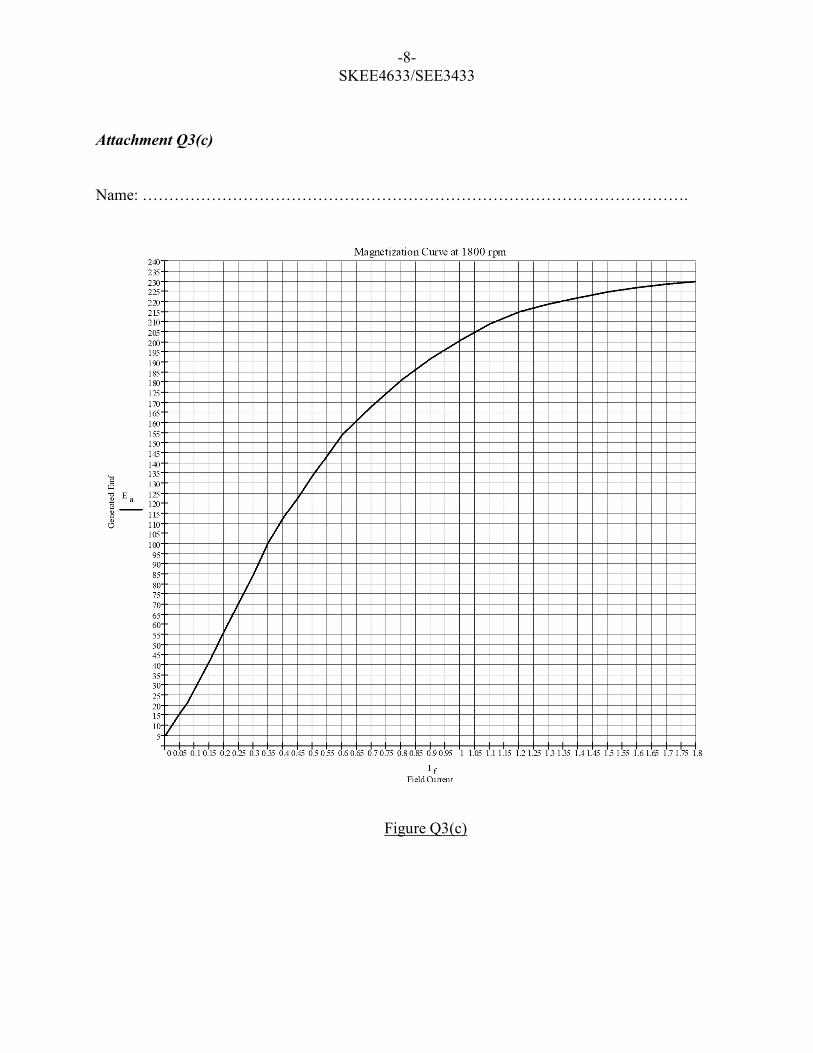
(b) A 240 kW, 200 V, 1800 rpm, Ra = 0.1 DC machine operated as shunt self-excited motor
has a magnetization characteristic at 1800 rpm as shown in Figure 3(c) in Attachment
Q3(c). The shunt field winding resistance, Rfw = 100 and the number of turns, Nf = 1200
turns/pole. The machine is connected to a 200 V DC supply. At no load condition, the
motor runs at 1800 rpm and the armature draws 10 A.
(i) Find the back emf Ea, field current If, and field resistance, Rf at no load condition.
[4 marks]
(ii) Find the speed of the motor when the rated current flows in the armature. Neglect the
armature reaction effect. [4 marks]
(iii) Find the rotational losses and efficiency of the motor when rated current flows in the
armature. Neglect the armature reaction effect and assume that rotational loss does not
change with speed. [5 marks]
(iv) Find the speed of the motor when the rated current flows in the armature. Consider the
effect of armature reaction at full-load is If(AR) = 0.15 A. Then, calculate the percentage
reduction of flux in the machine due to armature reaction.
[6 marks]
You must submit Attachment Q3(c) with your answer booklet
-5- SKEE4633/SEE3433
Question 4
(a) Draw the approximate per phase equivalent circuit of three-phase induction motor using.
Derive the steady-state torque equation generated by the induction motor, in term of
supply voltage V1, synchronous speed s, slip s and parameters of induction motor which
are 2R , R1, '2X and X1.
[6 marks]
(b) The parameters for a 3-phase star-connected, 415 V, 50 Hz, 1450 rpm four poles wound
rotor induction motor are as follows:
R1 = 0.20 2R = 0.25
X1 = 0.7 '2X = 0.7 Xm = 100
(i) Determine the synchronous speed, slip and the slip speed of the motor.
[4 marks]
(ii) To enable maximum torque produced at the motor starting, determine how much
external resistor/phase should be connected at the rotor side. Determine the motor
starting current. [6 marks]
(iii) The motor drives a constant load of 100 Nm at its rated speed. Calculate the
external rotor resistor/phase needed if the speed to be decreased from motor rated
speed to a speed of 1300 rpm. How much mechanical power is needed under this
condition? Assume no friction and windage loss. [6 marks]
(iv) Sketch the torque-speed characteristics of the motor and load to represent the
condition (iii) and also at its original rated condition.
[3 marks]
-6- SKEE4633/SEE3433
Question 5
(a) Sketch the per phase equivalent circuit of synchronous machine which consists of
armature resistance, Ra, and synchronous reactance, Xs, Label all circuit parameter and
electrical variables. Based on the equivalent circuit, draw the phasor diagram of the
synchronous generator and motor when it is supplying power at leading power factor.
[5 marks]
b) An 11.7 kV, 3-phase, four pole, 50 Hz, delta-connected synchronous generator has
negligible stator winding resistance and synchronous reactance of 30 Ω per phase at rated
terminal voltage. The generator is connected to constant voltage, constant frequency
infinite busbars.
(i) The generator is delivering 9 MW at power angle of 55 to busbars. Determine
per phase excitation voltage, line current, power factor and reactive power
supplied by generator. Draw a phasor diagram for this operating condition.
[5 marks]
(ii) The power output of the generator is increased to 12 MW by increasing the
steam supply and the excitation voltage is increased by 30%. Determine the
MVA, power angle, line current and power factor at which the machine now
works. [5 marks]
(iii) With the excitation voltage maintain at the same value as in part (ii) mechanical
power input (i.e. steam supply) is further increased until the generator is operating
at power factor of 0.9 leading. Determine the output power, reactive power,
current and power angle. [5 marks]
(vi) Draw the phasor diagram of (ii) and (iii) to indicate the change in generator steam
supplied with respect to the changes in excitation voltage.
[5 mark]
-7- SKEE4633/SEE3433
Attachment Q2(c)
Name: …………………………………………………………………………………………..
Figure Q2(c)
-8- SKEE4633/SEE3433
Attachment Q3(c)
Name: ………………………………………………………………………………………….
Figure Q3(c)
-9- SKEE4633/SEE3433
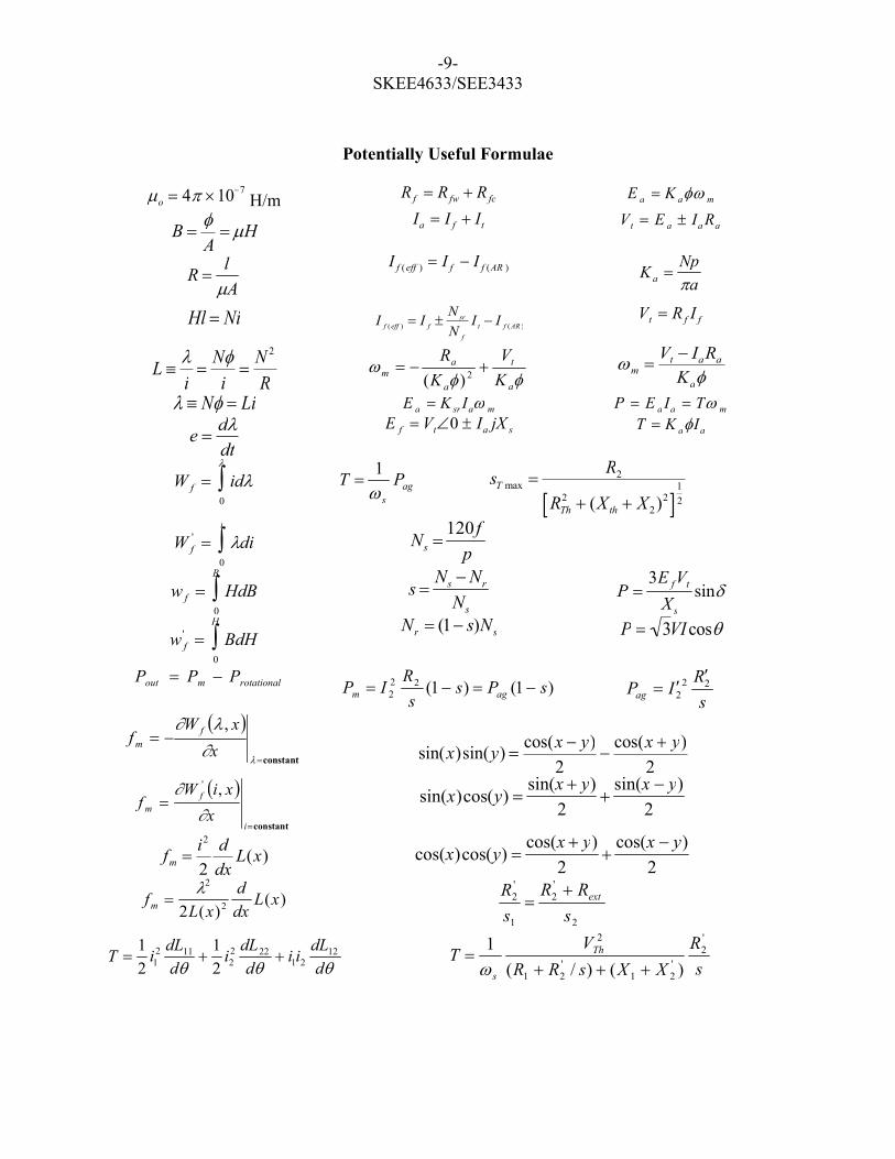
Potentially Useful Formulae
o 4 ´107 H/m R f R fw R fc E a K a m
B A H
Ia I f It V t E a Ia Ra
A
lR
I f (eff ) I f I f (AR ) K a Np
a
Hl Ni I f (eff ) I f N sr
N f
I t I f (AR ) Vt R f I f
L ºli
Ni
N 2
R
a
t
a
am K
V
K
R
2)( m
Vt IaRa
Ka
l º N Li E a K srIa m P E a Ia T m
e dldt
E f Vt0 Ia jX s T K aIa
W f idl0
l
ags
PT1
sT max R2
RTh2 (Xth X2)2[ ]
1
2
W f' ldi
0
i
Ns 120 f
p
w f HdB0
B
s Ns Nr
Ns
P 3E fVt
X s
sin
w f' BdH
0
H
Nr (1 s)Ns P 3VIcos
rotationalmout PPP )1()1(22
2 sPss
RIP agm
s
RIPag
222
constant
l
lx
xWf f
m
,
sin(x)sin(y) cos(x y)
2
cos(x y)
2
constant
i
fm x
xiWf
,'
sin(x)cos(y) sin(x y)
2
sin(x y)
2
fm i2
2
d
dxL(x) cos(x)cos(y)
cos(x y)
2
cos(x y)
2
fm l2
2L(x)2
d
dxL(x)
2
'2
1
'2
s
RR
s
R ext
T 1
2i1
2 dL11
d
1
2i2
2 dL22
d i1i2
dL12
d
s
R
XXsRR
VT Th
s
'2
'21
'21
2
)()/(
1