11i111111111111~~i[ii~i~il~~iw~11111 ~lil ...dilakllkan dengan melakukan pemerhatian secara visual,...
TRANSCRIPT

11I111111111111~~I[II~I~il~~IW~11111 ~lil~lllljlllllilllllllll .,.. • 30000002161879'
JUOUL:
Saya
UNIVERSITI TUN HUSSEIN ONN MALAYSIA
BORANG PENGESAHAN STATUS TESIS·
SYSTEMATIC INVESTIGATION OF FAILURE ANALYSIS ON A STEAM TRAP BYPASS TUBE IN A COAL FIRED POWER PLANT
SESI PENGAJIAN: 2007/2008
MOHO ARIF ANUAR BIN MOHO SALLEH (HURUF BESAR)
mcngaku mcmbcnarkan tesis (PSM/SarjanalOoktor Falsafah)* ini disimpan di Pcrpustakaan Universiti Tun Hussein Onn Malaysia dengan syarat-syarat kegunaan scpcrti berikut:
1. Tesis adalah hakmilik Universiti Tun Hussein Onn Malaysia. 2. Perpustakaan dibenarkan mcmbuat salinan untuk tujuan pengajian sahaja. 3. Perpustakaan dibenarkan membuat salinan tesis ini scbagai bahan pcrtukaran antara institusi
pengajian tinggi. 4. ** Sila tandakan (./ )
D SULIT
D TERHAO
D TIDAK TERHAO
(TANOAT~W ~ULIS) Alamat Tetap:
698F, Batu 3, Jalan Jcniang, 08300 Gurun, Kcdah, Malaysia.
TARIKH: 30 NOVEMBER 2007
(Mengandungi maklumat yang bcrdarjah kcsclamatan at au
kepentingan Malaysia sepcrti yang tcrmaktub di dalam
AKTA MALAYSIA RASMI1972)
(Mengandungi maklumat TERHAO yang tclah ditcntukan olch organisasiibadan di mana penyelidikan dijalankan)
ASSOC. PROF. DR.-ING. DARWIN SERA YANG (Nama Pcnyclia)
TARIKH:
CATATAN: * Potong yang tidak berkenaan. ** Jika tcsis ini SULIT atau TERHAO, sila lampirkan surat daripada pihak
berkuasalorganisasi berkcnaan dcngan mcnyatakan sckali scbab dan dikclaskan scbagai SULIT atau TERHAO.
• Tesis dimaksudkan sebagai tesis bagi Ijazah Doktor Falsafah dan Sarjana sccara pcnyclidikan, atau discrtai bagi pcngajian sccara kcrja kursus dan penyclidikan atau Laporan Projek Sarjana Muda (PSM).
"We hereby declare that we have read this thesis and we find that this thesis is
sufficient in terms of scope and qual ity for the award of Masters Degree in
Mechanical Engineering"
Signature
Name of Supervisor I
Date : ............... !.~ .... !!f.~~r... Q h1F
Signature
Name of Supervisor II : Dr Syahril D.Le
Date . .3 0 Irt~ iQ 6 (r(j ..........................................
SYSTEMATIC INVESTIGATION OF FAILURE ANALYSIS ON A STEAM
TRAP BYPASS TUBE IN A COALFIRED POWER PLANT
MOHD ARIF ANUAR MOHD SALLEH
A project report submitted in partial fulfillment of the requirements for the award of
Masters Degree in Mechanical Engineering
Faculty of Mechanical and Manufacturing
Tun Hussein Onn University of Malaysia
NOVEMBER 2007
11
"I declare that this project report entitled Systematic Investigation of Failure
Analysis on a Steam Trap Bypass Tube in a Coal Fired Power Plant is the result of
my own research as cited in the references. The project report has not been accepted
for any degree and is not concurrently submitted in candidate of any other degree"
Signature
Author
Date
........ f!~ ........ . : Mohd Arif Anuar Mohd Salleh
: 30 November 2007

111
ACKNOWLEDGMENT
In the name of Allah, the most gracious, the most merciful
Firstly, with the highest praise to Allah that I managed to complete this
project successfully. I would like to express my heartiest thankful to my supervisors,
Associate Professor Dr-Ing Danvin Sebayang and Dr. Syahril D.I.C for their
continuing guidance, valuable advices, ideas, support and encouragement in
completing this project successfully.
Besides that, I would like to express my special thanks to the lecturers,
technicians of mechanical laboratories and to those who involved and giving sincere
cooperation during completing this project.
I would also like to express my special thanks to my dad Prof Dato' Dr.
Mohd Salleh Hj. Din, my mum Prof. Madya Datin Maziah Onn, and also to my
siblings that inspired me and always supported me through this project. Besides that,
I would also like to express my special thanks to my friends and Noor Farhani Mohd
Alui.
IV
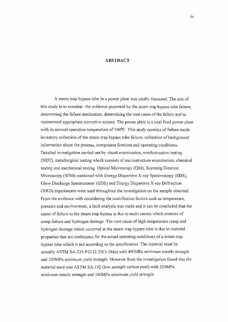
ABSTRACT
A steam trap bypass tube in a power plant was totally fractured. The aim of
this study is to examine the evidence presented by the steam trap bypass tube failure,
determining the failure mechanism, determining the root cause of the failure and to
recommend appropriate corrective actions. The power plant is a coal fired power plant
with its normal operation temperature of 540°C. This study consists of failure mode
inventory collection of the steam trap bypass tube failure, collection of background
information about the process, component function and operating conditions.
Detailed investigation carried out by visual examination, nondestructive testing
(NDT), metallurgical testing which consists of microstructure examination, chemical
testing and mechanical testing. Optical Microscopy (OM), Scanning Electron
Microscopy (SEM) combined with Energy Dispersive X-ray Spectroscopy (EDS),
Glow Discharge Spectrometer (GDS) and Energy Dispersive X-ray Diffraction
(XRD) experiments were used throughout the investigation on the sample obtained.
From the evidence with considering the contribution factors such as temperature,
pressure and environment, a fault analysis was made and it can be concluded that the
cause of failure to the steam trap bypass is due to multi causes which consists of
creep failure and hydrogen damage. The root cause of high temperature creep and
hydrogen damage which occurred at the steam trap bypass tube is due to material
properties that are inadequate for the actual operating conditions of a steam trap
bypass tube which is not according to the specification. The material must be
actually ASTM SA-335-P22 (2.25Cr-lMo) with 490MPa minimum tensile strength
and 320MPa minimum yield strength. However from the investigation found that the
material used was ASTM SA-l92 (low strength carbon steel) with 324MPa
minimum tensile strength and 180MPa minimum yield strength.
v
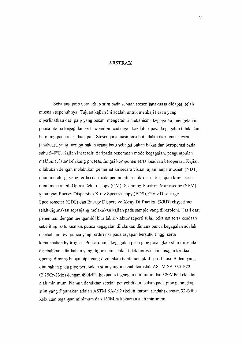
ABSTRAK
Sebatang paip perangkap stim pada sebuah stesen janakLlaSa didapati telah
musnah sepenuhnya. Tujuan kajian ini adalah untuk menkaji kesan yang
diperlihatkan dari paip yang pecah, mengetahui mekanisma kegagalan, mengetahui
punca utama kegagalan serta memberi cadangan kaedah supaya kegagalan tidak akan
berulang pada masa hadapan. Stesen janakuasa tersebut adalah dari jenis stesen
janakLlasa yang menggunakan arang batu sebagai bahan bakar dan beroperasi pada
suhu 540°C. Kajian ini terdiri daripada penemuan mode kegagalan, pengumpulan
maklumat latar belakang prosess, fungsi komponen serta keadaan beroperasi. Kajian
dilakLlkan dengan melakukan pemerhatian secara visual, ujian tanpa musnah (NDT),
ujian metalurgi yang terdiri daripada pemerhatian mikrostruktur, ujian kimia serta
ujian mekanikal. Optical Microscopy (OM), Scanning Electron Microscopy (SEM)
gabungan Energy Dispersive X-ray Spectroscopy (EDS), Glow Discharge
Spectrometer (GDS) dan Energy Dispersive X-ray Diffraction (XRD) eksperimen
telah digunakan sepanjang melakLlkan kajian pada sample yang diperolehi. Hasil dari
penemuan dengan mengambil kira faktor-faktor seperti suhu, tekanan serta keadaan
sekeliling, satu anal isis punca kegagalan dilakukan dimana punca kegagalan adalah
disebabkan dwi punca yang terdiri daripada rayapan bersuhu tinggi serta
kemusnahan hydrogen. Punca utama kegagalan pada pipe perangkap stim ini adalah
disebabkan sifat bahan yang digunakan adalah tidak bersesuaian dengan keadaan
operasi dim ana bahan pipe yang digunakan tidak mengikut spesifikasi. Bahan yang
digunakan pada pipe perangkap stirn yang musnah haruslah ASTM SA-335-P22
(2.2SCr-lMo) dengan 490MPa kekuatan tegangan minimum dan 320MPa kekLlatan
alah minimum. Namun demikian setelah penyelidikan, bahan pada pipe perangkap
stirn yang digunakan adalah ASTM SA-192 (keluli karbon rendah) dengan 324IvlPa
kekuatan tegangan minimum dan 180MPa kekuatan alah minimum.
VI
TABLE OF CONTENTS
CHAPTER TOPIC PAGE
TITLE
DECLARA TION 11
ACKNOWLEDGEMENT 111
ABSTRACT IV
ABSTRAK V
TABLE OF CONTENTS VI
LIST OF TABLES IX
LIST OF FIGURES X
LIST OF SYMBOLS XIV
LIST OF ABBREVIATIONS xv
LIST OF APPENDIX XVI
1 INTODUCTION
1.1 Statement of Problem 2
1.2 Objective of Study '"> .)
1.3 Scope of Study '"> .)
11 LITERA TURE REVIEW 5
2.1 Steam Trap Function and Operation 9
2.1.1 Steam Trap Bypass 11
2.1.2 Condensate Formation in Steam Trap Bypass 13
Tube
2.2 Material Damage and Mechanisms 13
2.2.1 Alloy Steel 18
Vll
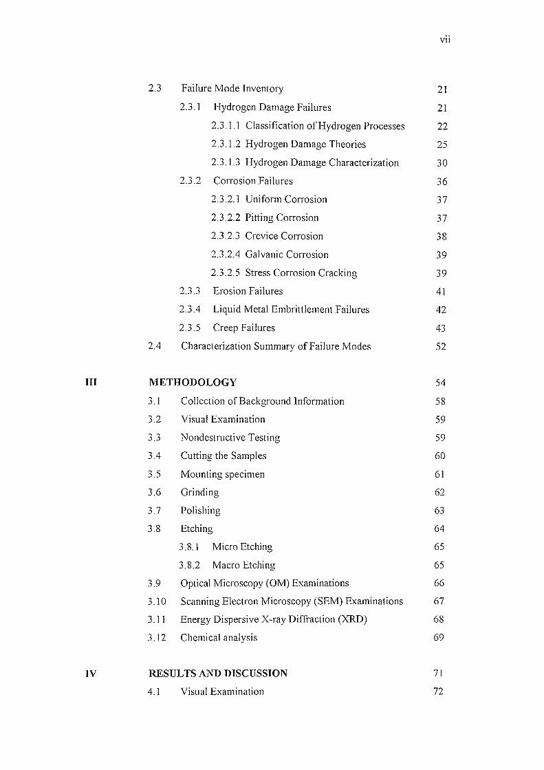
2.3 Failure Mode Inventory 21
2.3.1 Hydrogen Damage Failures 21
2.3.1.1 Classification of Hydrogen Processes 22
2.3.1.2 Hydrogen Damage Theories 25
2.3.1.3 Hydrogen Damage Characterization 30
2.3.2 Corrosion Failures 36
2.3.2.1 Uniform Corrosion 37
2.3.2.2 Pitting Corrosion 37
2.3.2.3 Crevice Corrosion 38
2.3.2.4 Galvanic Corrosion 39
2.3.2.5 Stress Corrosion Cracking 39
2.3.3 Erosion Failures 41
2.3.4 Liquid Metal Embrittlement Failures 42
2.3.5 Creep Failures 43
2.4 Characterization Summary of Failure Modes 52
ill METHODOLOGY 54
3.1 Collection of Background Information 58
3.2 Visual Examination 59
" " Nondestructive Testing 59 .:l . .:l
3.4 Cutting the Samples 60
3.5 Mounting specimen 61
3.6 Grinding 62
3.7 Polishing 63
3.8 Etching 64
3.8.1 Micro Etching 65
3.8.2 Macro Etching 65
3.9 Optical Microscopy (OM) Examinations 66
3.10 Scanning Electron Microscopy (SEM) Examinations 67
3.11 Energy Dispersive X-ray Diffraction (XRD) 68
3.12 Chemical analysis 69
IV RESULTS AND DISCUSSION 71
4.1 Visual Examination 72
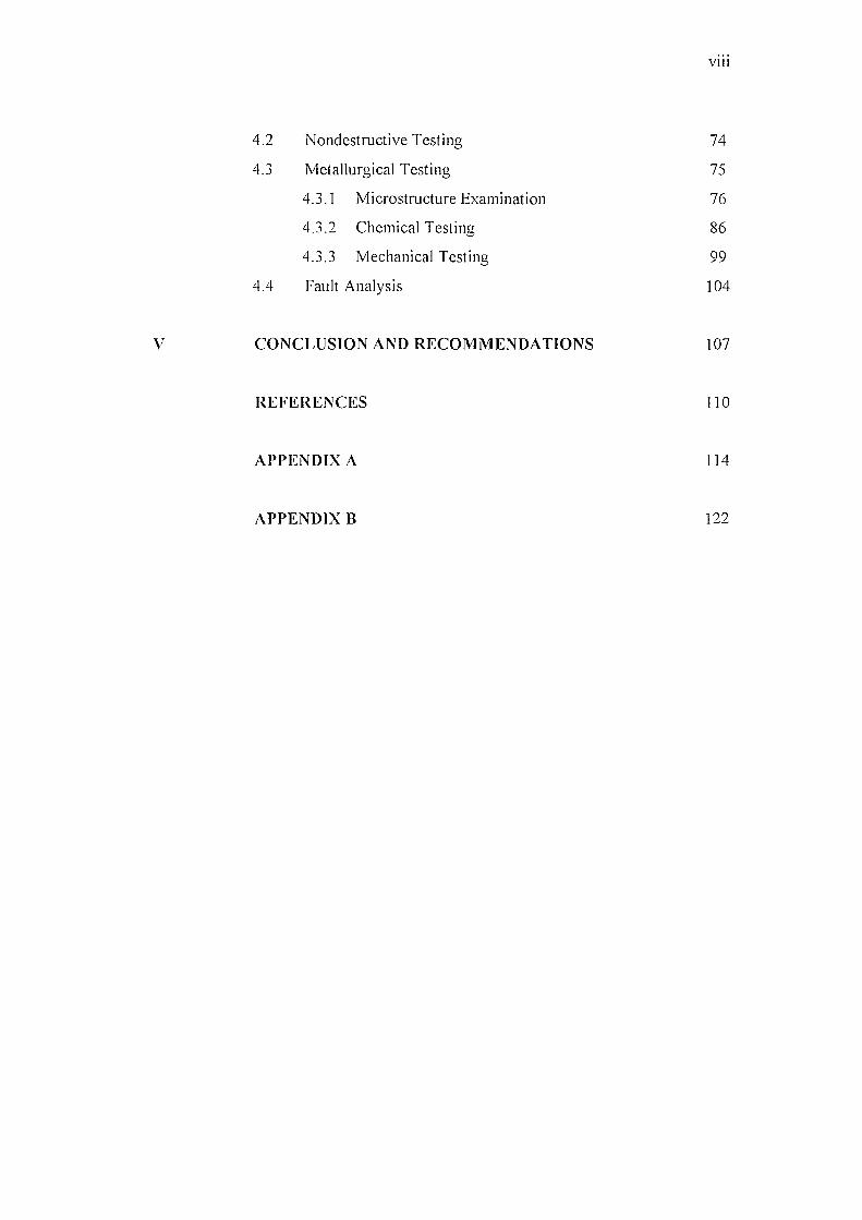
VIII
4.2 Nondestructive Testing 74
4.3 Metallurgical Testing 75
4.3.1 Microstructure Examination 76
4.3.2 Chemical Testing 86
4.3.3 Mechanical Testing 99
4.4 Fault Analysis 104
V CONCLUSION AND RECOMMENDATIONS 107
REFERENCES 110
APPENDIX A 114
APPENDIX B 122
IX
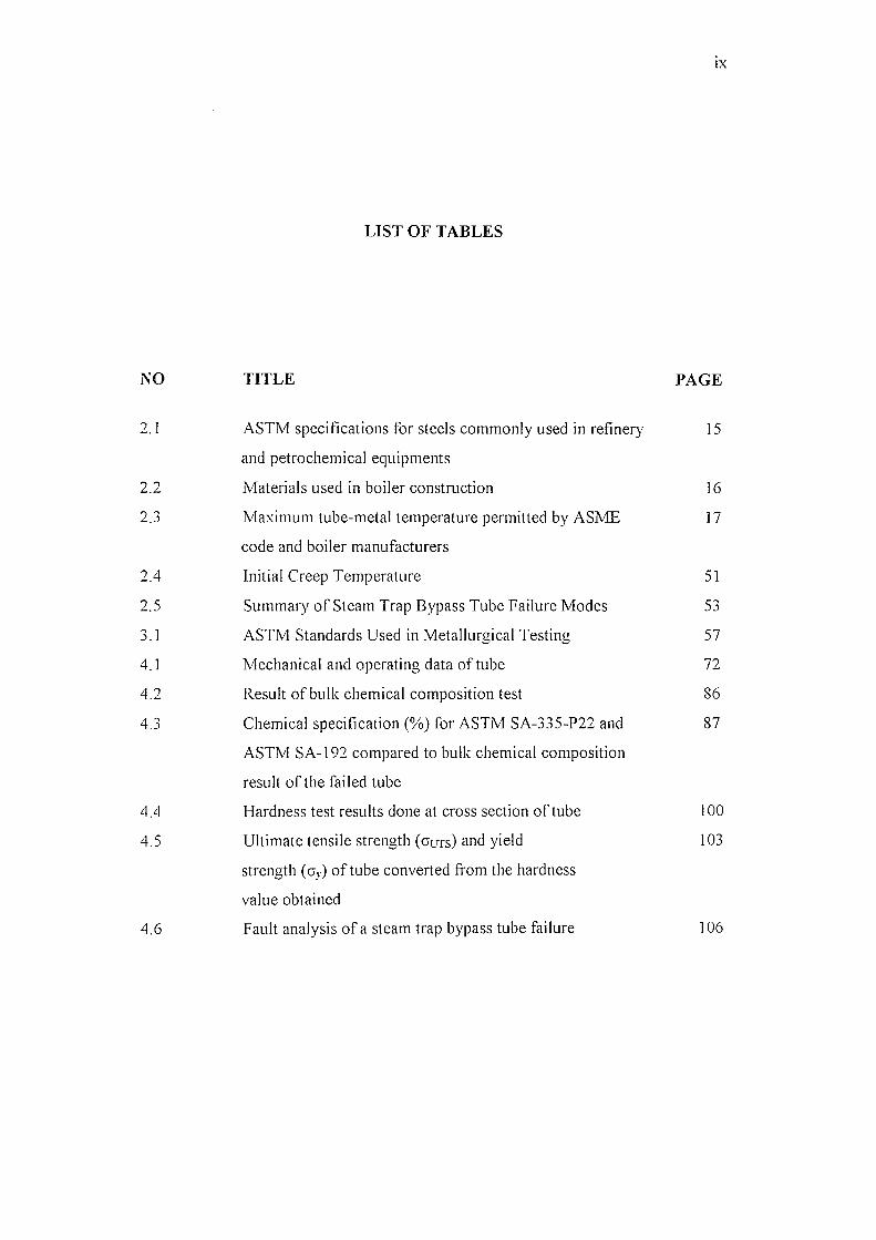
LIST OF TABLES
NO TITLE PAGE
2.1 ASTM specifications for steels commonly used in refinery 15
and petrochemical equipments
2.2 Materials used in boiler construction 16
2.3 Maximum tube-metal temperature permitted by ASME 17
code and boiler manufacturers
2.4 Initial Creep Temperature 51
2.5 Summary of Steam Trap Bypass Tube Failure Modes 53
3.1 ASTM Standards Used in Metallurgical Testing 57
4.1 Mechanical and operating data of tube 72
4.2 Result of bulk chemical composition test 86
4.3 Chemical specification (%) for ASTM SA-335-P22 and 87
ASTM SA-192 compared to bulk chemical composition
result of the failed tube
4.4 Hardness test results done at cross section of tube 100
4.5 Ultimate tensile strength (ours) and yield 103
strength (Oy) of tube converted from the hardness
value obtained
4.6 Fault analysis of a steam trap bypass tube failure 106
x
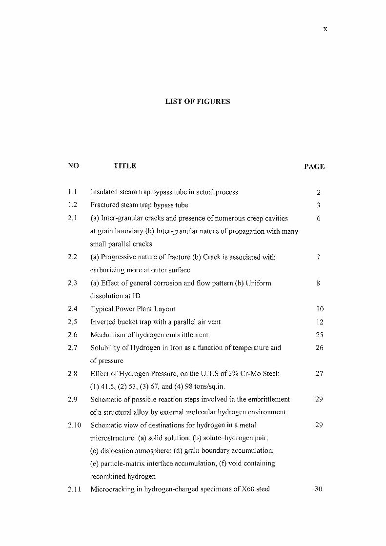
LIST OF FIGURES
NO TITLE PAGE
1.1 Insulated steam trap bypass tube in actual process 2
1.2 Fractured steam trap bypass tube '"' .)
2.1 (a) Inter-granular cracks and presence of numerous creep cavities 6
at grain boundary (b) Inter-granular nature of propagation with many
small parallel cracks
2.2 (a) Progressive nature of fracture (b) Crack is associated with 7
carburizing more at outer surface
2.3 (a) Effect of general corrosion and flow pattern (b) Uniform 8
dissolution at ID
2.4 Typical Power Plant Layout 10
2.5 Inverted bucket trap with a parallel air vent 12
2.6 Mechanism of hydrogen embrittlement 25
2.7 Solubility of Hydrogen in Iron as a function of temperature and 26
of pressure
2.8 Effect of Hydrogen Pressure, on the u.T.S of3% Cr-Mo Steel: 27
(1) 41.5, (2) 53, (3) 67, and (4) 98 tons/sq.in.
2.9 Schematic of possible reaction steps involved in the embrittlement 29
of a structural alloy by ex1ernal molecular hydrogen environment
2.10 Schematic view of destinations for hydrogen in a metal 29
microstructure: (a) solid solution; (b) solute-hydrogen pair;
(c) dislocation atmosphere; (d) grain boundary accumulation;
(e) particle-matrix interface accumulation; (f) void containing
recombined hydrogen
2.11 Microcracking in hydrogen-charged specimens ofX60 steel 30
Xl
2.12 Transition between brittle and ductile fracture 31
2.13 (a) Fracture surface observed in a specimen that fractured by brittle "J -)-
mode. (b) Large longitudinally oriented cracks
2.14 Fracture Surfaces of Corrosion-induced Hydrogen Embrittlement in "J -)-
Aluminium Alloy 2024
2.15 Fish eyes on the fracture surface 33
2.16 Cleavage fracture of the aureole of a fish eye region 34
2.17 Opened bubble on a galvanized steel surface 34
2.18 Partially intercrystalline fracture with ductile marks on the grain 35
faces
2.19 Decarburized 1060 steel heated at 1205°C at 1 OOX magnification 36
2.20 Typical undermining foml of pitting in the microstructure of an 38
aluminium alloy wrought product (100X)
2.21 Cross section of stress corrosion crack in stainless steel (500X) 40
2.22 Impingement failure of elbow in steam condensate line 41
2.23 Erosion corrosion of slide valve at 900°C in petroleum refinery 42
2.24 Schematic creep curve 44
2.25 Microstructural and fractographic features of creep fhcture 46
mechanism
2.26 Fractography showing extensive plastic deformation due to fracture 46
at high temperature
2.27 Schematic illustration of formation of (a) wedge and (b) creep cavities 47
2.28 Microstructures from creep specimens showing creep cavities and 47
wedge cracks (a) Cracks initiated at triple boundaries (b) Beadlike
cracks along grain boundaries
2.29 Fracture mechanism map for pure iron 48
2.30 Fracture mechanism map for a 2.25 Cr1 Mo steel containing 0.13wt%C 49
3.1 Sequence of fai lure investigation 55
3.2 Sequence of metallography investigation 56
3.3 The position of samples 58
3.4 Illustration of sample taken 60
3.5 Picture of wire cut E1ectrodischarge rVlachining (Eorvl) 61
3.6 (a) Picture of standard mounting machine (b) Close up picture of 62
sample placement for mounting procedure
XII
3.7 Picture of mounted sample 62
3.8 Picture of standard grinding machine 63
3.9 Picture of standard polisher machine 64
3.10 Sample macro etched in hot 10% nital for 20 minutes 66
3.11 Picture of Optical Microscope (OM) 67
3.12 Picture of Scanning Electron Microscope (SEM) 68
3.13 Picture of Energy Dispersive X-ray Diffraction (XRD) 69
4.1 Sample at fracture surface showed brittle appearance 72
4.2 Fishmouth appearance that fractured apart due to high pressure 73
4.3 Longitudinal cracks in inside tube surface with the presence of 73
oxide scale
4.4 Longitudinal cracks grow and initiate the tube fracture 74
4.5 Red dye penetration examination at (a) outside tube surface and 75
(b) inside tube surface showing cracks
4.6 Inside tube surface shows similar crack distance (0.9 mm) 77
between the longitudinal cracks (5X)
4.7 OM micrograph of cross section inside tube edge shows 0.35 mm 78
thickness of oxide scale in inside tube surface (20X)
4.8 (a) Cross section of sample macro-etched with hot 10% nital shows 79
light area at inside tube. (b) Failure mode inventory: Decarburized
1060 steel heated at 1205°C at 100X magnification
4.9 Microstructure examination with 20X magnification using optical 80
microscope, (a) cross section of inside tube edge (b) cross section
of outside tube edge (c) inside tube surface (d) outside tube surface.
4.10 OM micrograph at cross section of inside tube showing the grain size 81
differences between the grains near and far from the inside tube edge.
4.11 Illustration of how a refinement in grain size improves resistance to 83
hydrogen failure as measured by the time to failure of two strengths
of AISI 4340 steels
4.12 SEM micrograph at the cross section of inside tube edge and outside 84
tube edge shows graphitized microstructure, microvoids, pores and
intergranular cracks
4.13 OM micrograph at cross section of inside tube edge shows voids 84
and grooves (small cusps) in v-shaped

XIII
4.14 SEM micrograph of fracture surface with 20X magnification 85
4.15 SEM micrograph with higher magnification (500X) shows 85
dimples, brittle facets, cleavage fracture and hair line cracks
4.16 EDS analysis to reveal decarburization at the (a) cross section of 88
inside tube edge sample in the circle area (250X), (b) along the
grain boundaries (2200X)
4.17 Graph of chemical composition along the grain boundaries at point 001 88
4.18 Graph of chemical composition along the grain boundaries at point 002 89
4.19 Graph of chemical composition along the grain boundaries at point 003 89
4.20 EDS analysis to reveal decarburization done linearly at different grains 89
at cross section of inside tube edge sample (2200X)
4.21 Graph of chemical composition linearly at different grains at point 001 90
4.22 Graph of chemical composition linearly at different grains at point 002 90
4.23 Graph of chemical composition linearly at different grains at point 003 90
4.24 Graph of chemical composition linearly at different grains at point 004 91
4.25 Graphs of element percentage at points along the grain boundaries 91
of cross section inside tube edge sample
4.26 Graphs of element percentage at points linearly at different grains 92
of cross section inside tube edge sample
4.27 Mapping image at cross section of inside tube edge 94
4.28 Mapping image at cross section of outside tube edge 95
4.29 Pattern diffraction of the internal tube 97
4.30 Pattern diffraction of the outer tube 98
4.31 Hardness test points carried out at cross section of tube 99
4.32 Long cylindrical tube with an external radial edge crack extending 102
from the boundary subjected to a uniform internal pressure. KI is
for the edge crack
4.33 Mechanical properties graph offailed sample 104
4.34 Types of failures that tend to be the cause of steam trap bypass 105
tube failure
HV
vy
c
VUTS
e
v
LIST OF SYMBOLS
Degrees Celcius
Degrees Farenheit
Percentage
Grains cut by the circumference
Grains in area
Magnification
Number of grains per unit area
Number of grains contained in unit volume
Vickers Hardness
Yield strength
Constant
Ultimate Tensile Strength
Elongation
Stress
:\1\"
SEM
OM
EDS
GDS
XRD
EDM
NDT
OD
ID
ASTM
UTS
LIST OF ABBREVIATIONS
Scanning Electron Microscopy
Optical Microscope
Energy Dispersive X-ray Spectroscopy
Glow Discharge Spectrometer
Energy Dispersive X-ray Diffraction
Electrodischarge Machining
Non Destructive Testing
Outside Diameter
Inside Diameter
American Society for Testing Materials
Ultimate Tensile Strength
xv
APPENDIX
A
B
LIST OF APPENDIX
TITLE
Microstructure Examination Pictures
Chemical Analysis Data Result
PAGE
114
122
XVI
CHAPTER I
INTRODUCTION
In a power plant industry, failures usually occur on tubes and pipelines.
Establishing the causes offailures provides infonnation of improvements in design,
operating procedures and the use of components. Failure analysis is an engineering
approach to detennine how and why an equipment or component has failed. Failure occurs
when it does not meet its requirements. Failure analysis can also be defined as an
investigation to detennine the underlying reasons for the nonconfonnance to system
requirements and is performed to identify nonconformance root causes and to recommend
appropriate corrective actions [1].
A failure investigation and subsequence analysis should detennine the primary
cause of a failure, and based on the detennination, corrective action should be initiated
that will prevent similar failures. Although the sequence is subject to variation, depending
upon the nature of a specific failure, the principal stages that comprise the investigation
and analysis offailure is firstly the collection of background data and selection of samples
[2]. Preliminary examination of the failed part which includes visual examination and
record keeping will be the next stage of investigation. Nondestructive testing and
mechanical testing that includes hardness test can also be done as part of the investigation.
The next stage is tl1e selection, identification, preservation or cleaning of all specimens.
Macroscopic examination and analysis is the next stage where fracture surface, secondary
cracks and other surface phenomena will be identified. After the macroscopic
examination, microscopic examination and analysis is the ne».i stage. Selection and
preparation of metallographic sections will need to be done thus the examination and
analysis of metallographic sections. From the examinations, failure mechanism will be
determined. For further investigation, chemical analysis which includes determining the
bulk, local, surface corrosion products, deposit or coatings will be done. From the results,
analysis of fracture mechanics will then be determined. Testing under simulated service
conditions can be done for further analysis. The fmal stage is the analysis of all the
evidence, formulation of conclusion and writing the report [2].
1.1 Statement of Problem
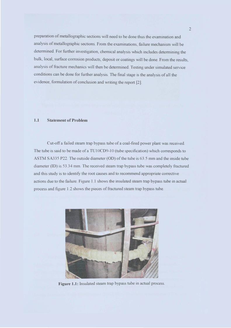
Cut-off a failed steam trap bypass tube of a coal-fired power plant was received.
The tube is said to be made of a T01 OCD9-1 0 (tube specification) which corresponds to
ASTM SA335 P22. The outside diameter (OD) ofthe tube is 63 .5 mm and the inside tube
diameter (ID) is 53 .34 mm. The received stearn trap bypass tube was completely fractured
and this study is to identify the root causes and to recommend appropriate corrective
actions due to the failure. Figure 1.1 shows the insulated stearn trap bypass tube in actual
process and figure 1.2 shows the pieces of fractured steam trap bypass tube.
Figu."e 1.1: Insulated stearn trap bypass tube in actual process.
2
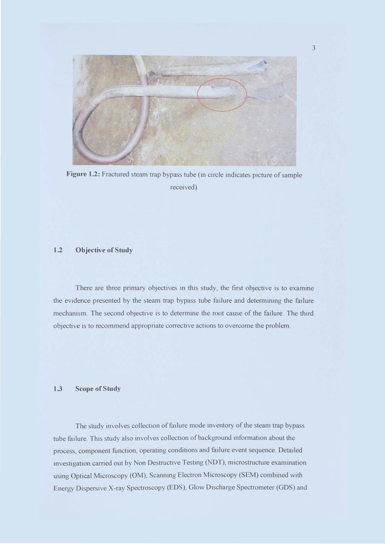
Figm'e 1.2: Fractured steam trap bypass tube (in circle indicates picture of sample
received).
1.2 Objective of Study
3
There are three primary objectives in this study, the first objective is to examine
the evidence presented by the steam trap bypass tube failure and determining the failure
mechanism. The second objective is to detennine the root cause of the failure . The third
objective is to recommend appropriate corrective actions to overcome the problem.
1.3 Scope of Study
The study involves collection offailure mode inventory of the steam trap bypass
tube failure. This study also involves collection of background information about the
process, component function, operating conditions and failure event sequence. Detailed
investigation carried out by Non Destructive Testing (NDT), microstructure examination
using Optical Microscopy (OM), Scanning Electron Microscopy (SEM) combined with
Energy Dispersive X-ray Spectroscopy (EDS), Glow Discharge Spectrometer (GDS) and

Energy Dispersive X-ray Diffraction (XRD) testing on the sample will be done. From
these results, analysis of the result will be done to determine the root cause of the steam
trap bypass tube failure.
4