mohd amir fikri awang ( cd 5327 )pdf(1)
TRANSCRIPT
DC MOTOR SPEED CONTROLLER
MOHD AMIR FIKRI BIN AWANG
A Thesis Submitted in Fulfillment for the
Requirement Award of the degree of
Bachelor of Electrical Engineering (Power Systems)
Faculty of Electrical and Electronics Engineering
Universiti Malaysia Pahang
NOVEMBER 2010
ii
“All the trademark and copyrights use herein are property of their respective owner.
References of information from other sources are quoted accordingly; otherwise the
information presented in this report is solely work of the author.”
Signature : ………………………………………
Author : MOHD AMIR FIKRI BIN AWANG
Date : 11 NOVEMBER 2011
iii
“I hereby acknowledge that the scope and quality of this thesis is qualified for the
award of the Bachelor Degree of Electrical Engineering (Power Systems)”
Signature : …………………………………...
Name : ENCIK RUHAIZAD BIN ISHAK
Date : 11 NOVEMBER 2010

v
ACKNOWLEDGMENT
The name of Allah the Most Gracious, Most Merciful…
Thanks to Allah the All Mighty, All Sovereign and All Supreme for giving me
good and health to finish my project.
First and foremost, I wish to extend my appreciation and thanks to my supervisor,
Encik Ruhaizad bin Ishak, for his supervision and various advice on how to complete this
project.
I particular, I wish to acknowledge the support given from my family who are
always there on my ups and down and pray for me.
Lastly, thanks to all my friends for their suggestion and help to excellent in all
aspect of my project.
And for those who give me support direct and indirectly to finish my final year
project, thank you very much. May Allah bless all of you.
vi
ABSTRACT
The automatic control has played a vital role in the advance of engineering and
science. Nowadays in industries, the control of direct current (DC) motor is a common
practice thus the implementation of DC motor of controller speed is important. The main
purpose of motor speed control is to keep the rotation of the motor at the preset speed and
to drive a system at the demanded speed. When used in speed application, speed feedback
control the DC motor’s speed or confirms that the motor is rotating at the desired speed.
To maintain the speed, it requires the speed feedback at all times. The speed of a DC
motor usually is directly proportional to the supply voltage. For instance, if we reduce the
supply voltage from 12 Volts to 6 Volts the motor will run at half or lower the speed. The
advantages used DC motor is provide excellent speed control for acceleration and
deceleration with effective and simple torque control. The fact that the power supply of a
DC motor connects directly to the field of the motor allows for precise voltage control,
which is necessary with speed and torque control applications. The common methods are
used to control speed DC motor is Proportional Integral Derivative (PID) and PC based to
control it. In this project, the method use as controller is Programmable Interface
Controller (PIC) microcontroller for the electric current control to drive a motor. The
expectation of this project is to get the precise the demanded speed and to drive a motor
at that speed.
vii
ABSTRAK
Kawalan automatik telah memainkan peranan penting dalam kemajuan ilmu sains
dan kejuruteraan. Pada masa kini di industri, kawalan motor arus terus (AT) adalah
amalan umum sehingga pelaksanaan kawalan kelajuan motor AT adalah penting. Tujuan
utama dari kawalan kelajuan motor adalah menjaga pusingan motor pada kelajuan preset
dan untuk memacu sistem di kelajuan diigini. Apabila digunakan dalam aplikasi kelajuan,
kelajuan kawalan suap balik kelajuan motor AT atau menegaskan bahawa motor sedang
berputar pada kelajuan yang dikehendaki. Untuk mempertahankan kelajuan, memerlukan
maklum balas kelajuan bila-bila masa. Kelajuan motor AT biasanya berbanding lurus
dengan tegangan bekalan. Sebagai contoh, jika kita mengurangkan bekalan voltan
daripada 12 Volt ke 6 Volts motor akan berjalan pada setengah atau lebih rendah
kelajuan. Kebaikan yang digunakan adalah motor AT memberikan kawalan kelajuan
yang sangat baik untuk percepatan dan perlambatan dengan kawalan torsi berkesan dan
sederhana. Fakta bahawa bekalan elektrik dari motor AT berhubung langsung dengan
bidang motor membolehkan kawalan voltan yang tepat, yang diperlukan dengan aplikasi
kawalan kelajuan dan torsi. Kaedah yang umum adalah digunakan untuk mengawal
kelajuan motor DC adalah Proportional Integral Derivatif (PID) dan PC berasaskan
mengendalikannya. Dalam projek ini, penggunaan kaedah sebagai pengendali adalah
Programmable Interface Controller (PIC) mikropengawal untuk mengawal arus elektrik
untuk menggerakkan motor. Harapan dari projek ini adalah untuk mendapatkan kelajuan
yang tepat menuntut dan menggerakkan motor pada kelajuan itu.
viii
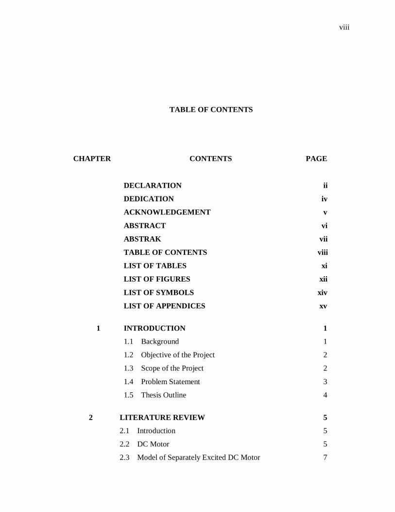
TABLE OF CONTENTS
CHAPTER CONTENTS PAGE
DECLARATION ii
DEDICATION iv
ACKNOWLEDGEMENT v
ABSTRACT vi
ABSTRAK vii
TABLE OF CONTENTS viii
LIST OF TABLES xi
LIST OF FIGURES xii
LIST OF SYMBOLS xiv
LIST OF APPENDICES xv
1 INTRODUCTION 1
1.1 Background 1
1.2 Objective of the Project 2
1.3 Scope of the Project 2
1.4 Problem Statement 3
1.5 Thesis Outline 4
2 LITERATURE REVIEW 5
2.1 Introduction 5
2.2 DC Motor 5
2.3 Model of Separately Excited DC Motor 7
ix
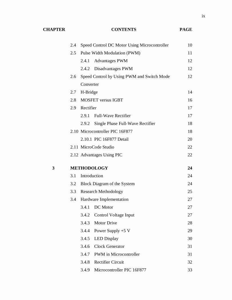
CHAPTER CONTENTS PAGE
2.4 Speed Control DC Motor Using Microcontroller 10
2.5 Pulse Width Modulation (PWM) 11
2.4.1 Advantages PWM 12
2.4.2 Disadvantages PWM 12
2.6 Speed Control by Using PWM and Switch Mode 12
Converter
2.7 H-Bridge 14
2.8 MOSFET versus IGBT 16
2.9 Rectifier 17
2.9.1 Full-Wave Rectifier 17
2.9.2 Single Phase Full-Wave Rectifier 18
2.10 Microcontroller PIC 16F877 18
2.10.1 PIC 16F877 Detail 20
2.11 MicroCode Studio 22
2.12 Advantages Using PIC 22
3 METHODOLOGY 24
3.1 Introduction 24
3.2 Block Diagram of the System 24
3.3 Research Methodology 25
3.4 Hardware Implementation 27
3.4.1 DC Motor 27
3.4.2 Control Voltage Input 27
3.4.3 Motor Drive 28
3.4.4 Power Supply +5 V 29
3.4.5 LED Display 30
3.4.6 Clock Generator 31
3.4.7 PWM in Microcontroller 31
3.4.8 Rectifier Circuit 32
3.4.9 Microcontroller PIC 16F877 33
x
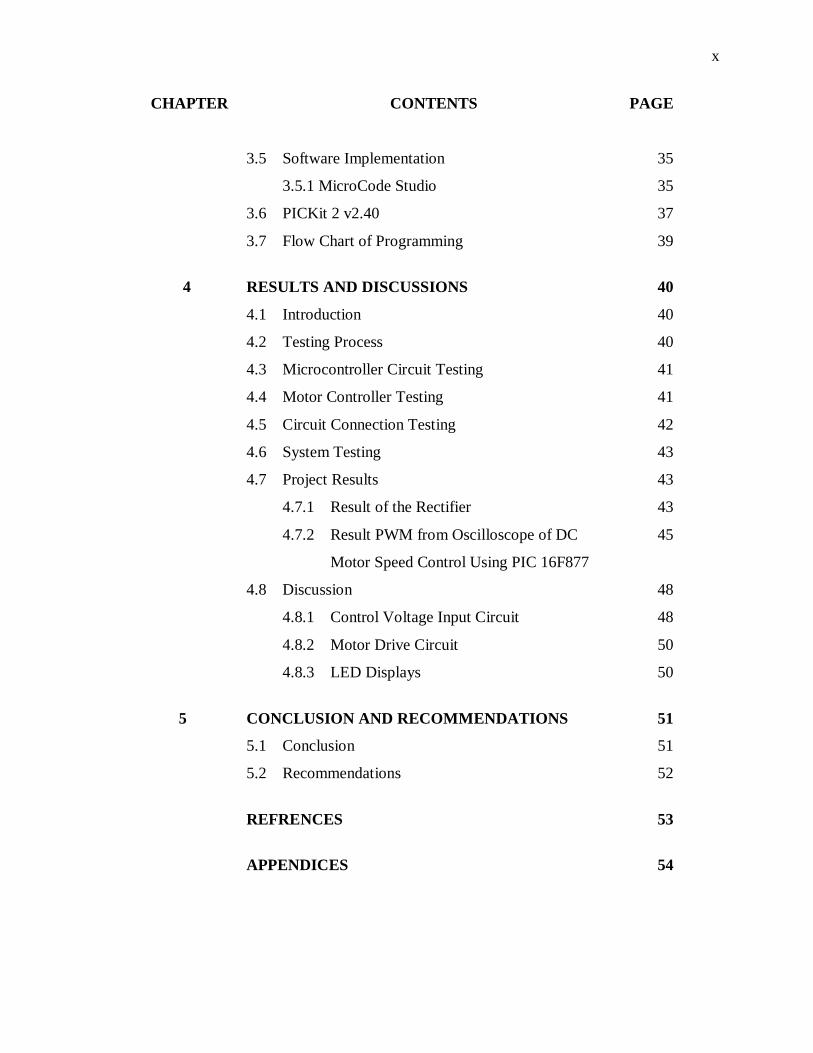
CHAPTER CONTENTS PAGE
3.5 Software Implementation 35
3.5.1 MicroCode Studio 35
3.6 PICKit 2 v2.40 37
3.7 Flow Chart of Programming 39
4 RESULTS AND DISCUSSIONS 40
4.1 Introduction 40
4.2 Testing Process 40
4.3 Microcontroller Circuit Testing 41
4.4 Motor Controller Testing 41
4.5 Circuit Connection Testing 42
4.6 System Testing 43
4.7 Project Results 43
4.7.1 Result of the Rectifier 43
4.7.2 Result PWM from Oscilloscope of DC 45
Motor Speed Control Using PIC 16F877
4.8 Discussion 48
4.8.1 Control Voltage Input Circuit 48
4.8.2 Motor Drive Circuit 50
4.8.3 LED Displays 50
5 CONCLUSION AND RECOMMENDATIONS 51
5.1 Conclusion 51
5.2 Recommendations 52
REFRENCES 53
APPENDICES 54
xi
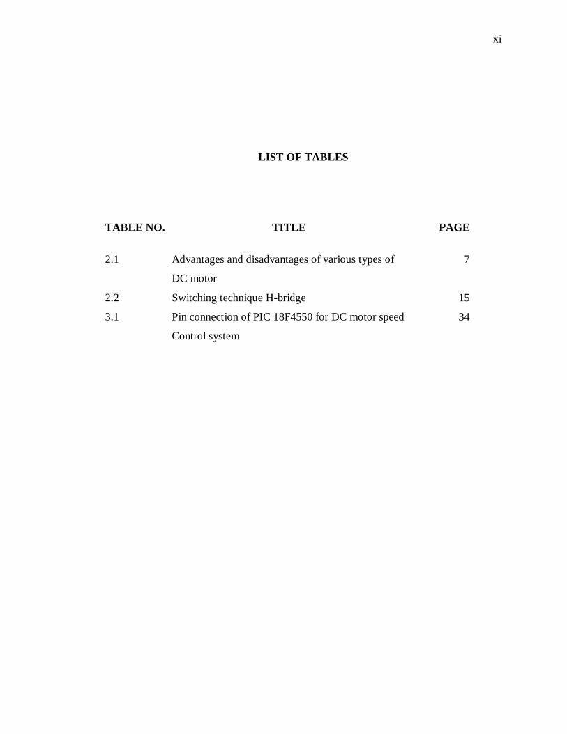
LIST OF TABLES
TABLE NO. TITLE PAGE
2.1 Advantages and disadvantages of various types of 7
DC motor
2.2 Switching technique H-bridge 15
3.1 Pin connection of PIC 18F4550 for DC motor speed 34
Control system
xii
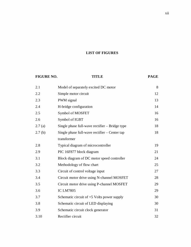
LIST OF FIGURES
FIGURE NO. TITLE PAGE
2.1 Model of separately excited DC motor 8
2.2 Simple motor circuit 12
2.3 PWM signal 13
2.4 H-bridge configuration 14
2.5 Symbol of MOSFET 16
2.6 Symbol of IGBT 16
2.7 (a) Single phase full-wave rectifier – Bridge type 18
2.7 (b) Single phase full-wave rectifier – Center tap 18
transformer
2.8 Typical diagram of microcontroller 19
2.9 PIC 16F877 block diagram 21
3.1 Block diagram of DC motor speed controller 24
3.2 Methodology of flow chart 25
3.3 Circuit of control voltage input 27
3.4 Circuit motor drive using N-channel MOSFET 28
3.5 Circuit motor drive using P-channel MOSFET 29
3.6 IC LM7805 29
3.7 Schematic circuit of +5 Volts power supply 30
3.8 Schematic circuit of LED displaying 30
3.9 Schematic circuit clock generator 31
3.10 Rectifier circuit 32
xiii
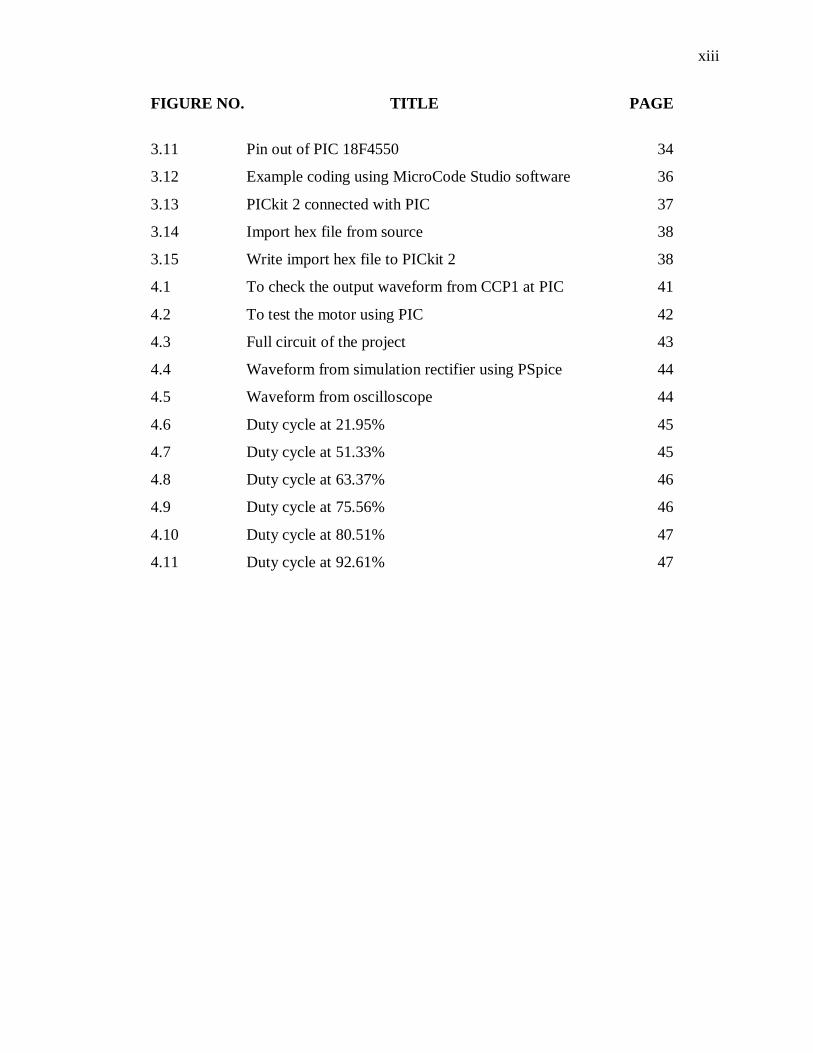
FIGURE NO. TITLE PAGE
3.11 Pin out of PIC 18F4550 34
3.12 Example coding using MicroCode Studio software 36
3.13 PICkit 2 connected with PIC 37
3.14 Import hex file from source 38
3.15 Write import hex file to PICkit 2 38
4.1 To check the output waveform from CCP1 at PIC 41
4.2 To test the motor using PIC 42
4.3 Full circuit of the project 43
4.4 Waveform from simulation rectifier using PSpice 44
4.5 Waveform from oscilloscope 44
4.6 Duty cycle at 21.95% 45
4.7 Duty cycle at 51.33% 45
4.8 Duty cycle at 63.37% 46
4.9 Duty cycle at 75.56% 46
4.10 Duty cycle at 80.51% 47
4.11 Duty cycle at 92.61% 47
xiv
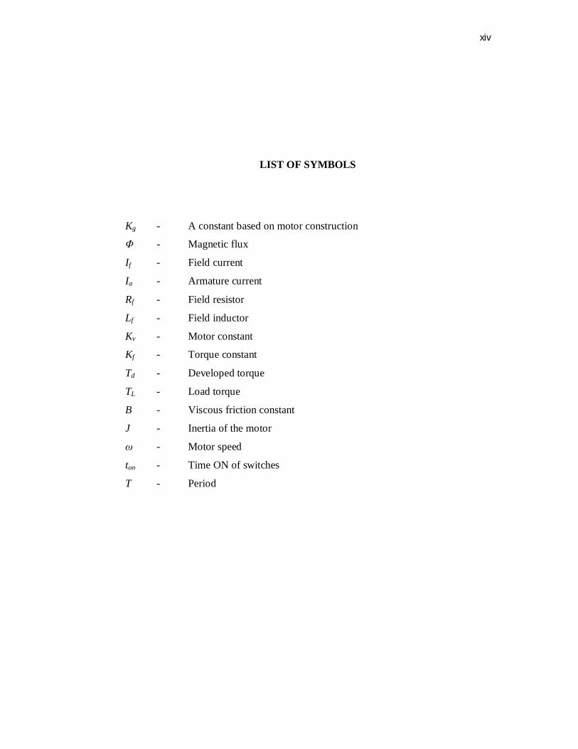
LIST OF SYMBOLS
Kg - A constant based on motor construction
Φ - Magnetic flux
If - Field current
Ia - Armature current
Rf - Field resistor
Lf - Field inductor
Kv - Motor constant
Kf - Torque constant
Td - Developed torque
TL - Load torque
B - Viscous friction constant
J - Inertia of the motor
ω - Motor speed
ton - Time ON of switches
T - Period
xv
LIST OF APPENDICES
APPENDIX TITLE PAGE
A Flow Chart of Programming 54
(3.7 Flow Chart of Programming)
B Instruction Coding 57
C Datasheet PIC 16F877 64
D Datasheet Power MOSFET IRF 540N 70
E Datasheet BJT Transistor 2SC1815 75
CHAPTER 1
INTRODUCTION
1.1 Background The direct current (DC) motor is a device that used in many industries in
order to convert electrical energy into mechanical energy. This is all result from the
availability of speed controllers is wide range, easily and many ways. In most
applications, speed control is very important. For example, if we have DC motor in
radio controller car, if we just apply a constant power to the motor, it is impossible to
maintain the desired speed. It will go slower over rocky road, slower uphill, faster
downhill and so on. So, it is important to make a controller to control the speed of
DC motor in desired speed.
DC motor plays a significant role in modern industry. The purpose of a motor
speed controller is to take a signal representing the demanded speed, and to drive a
motor at that speed. There are numerous applications where control of speed is
required, as in rolling mills, cranes, hoists, elevators, machine tools, transit system
and locomotive drives. These applications may demand high-speed control accuracy
and good dynamic responses.
In home appliances, washers, dryers and compressors are good example.
There are many applications in our life that requires DC motor speed control. In
conclusion, the simplicity of control speed made DC motors to be common in
devices ranging from toys, house appliance and robotics to industrial application.
2
1.2 Objective of the Project Basically, these projects are listing three main objectives. The objectives are a
guideline and goal in order to complete this project. This project is conducted to
achieve the following objectives:
i. To design the hardware of the controller to control DC motor speed.
ii. To develop controller using microcontroller as programming.
iii. To develop precisely control the DC motor.
1.3 Scope of the Project There are two scopes in this project which is hardware development and
software development.
For the first scope which is hardware development are three main sections
and those section are:
i. To design a circuit for to control voltage input.
ii. To design a for the motor drive.
iii. To design a circuit for the PIC 16F877.
iv. To design the rectifier circuit.
For the second scope which is the software development, there are two main
sections and that section are:
i. To develop a software using the PBasic of the PIC 16F877.
ii. To simulate the control system using Proteus software.
3
1.4 Problem Statement
The most issue discusses in speed controller is regarding their efficiency and
reliability. The efficiency element is important in order to save cost. The efficiency
of speed controller is depending on method control system. The speed controller
usually control in analog system.
An analog signal has a continuously varying value, with infinite resolution in
both time and magnitude. For example, a 5 V is an analog and its output voltage is
not precisely 5 V, changes over time, and can take any real-numbered value.
Similarly, the amount current drawn from a battery is not limited to a finite set of
possible value. Analog signals are distinguishable from digital signals because the
latter away take values only from a finite set of predetermined possibilities.
DC motor widely used in speed control systems which needs high control
requirement such as rolling mill, double-hulled tanker and high precision digital
tools. So, it is crucial to control the motor sped in order to achieve good production.
One of the most common methods to drive a DC motor is by using PWM signals
respect to the motor input voltage.
Manual controller is also not practical in the technology era because it can
waste time and cost. Operation cost regarding controller is got attention from
industrial field. In order to reduce cost and time, we suggest making a controller
based on computer because it is portable. The user can monitor their system at
certain place without need to going the plant (machine) especially in industrial
implementation. From that, the man power can be reduced and reserve with
computer which is more precise and reliable.
The other product regarding this project where control motor via computer
may be commercialized but their cost is very expensive. The hardware of this
product may be complicated and maintenance cost is higher. The low cost electronic
devices can be designed to make a speed controller system.
4
1.5 Thesis Outline This thesis consists five chapters. In first chapter, it discusses about
introduction and overview about this project includes background, objectives and
scope of projects.
Chapter two is explanations about literature review as study material and
references. The topics that I have studied are about the other method of speed control
to compare and analysis their advantages and disadvantages. From the literature
review, knowledge can be gained thus implement in this project.
The methodology that I have done are discusses on chapter three. This is
explanations about the method used to complete hardware and software. Chapter four
are discusses of the result and analysis of this project. For the last chapter are
describes conclusion and future recommendation to make this project greatly.
This thesis included with references and appendices. We can refer the further
information about this project in references which is states the source and their
authors. Datasheet of the components, photo and other information also placed on the
appendices part.
CHAPTER 2
LITERATURE REVIEW
2.1 Introduction
There are two main types of electrical motors. There are direct current (DC)
motor and alternating current (AC) motor. The reference of DC and AC refers how
the electrical current is transferred through and from the motor. Both the types of the
motors have different functions and applications. DC motors come in two general
types. Its brushes and be brushless (synchronous motor). Then, AC motor come in
two types, which is single phase and three phase.
2.2 DC Motor
There are many types of DC motor that are available such as stepper motor,
permanent magnet DC (PMDC), printed circuit board (PCB) motor and others. These
motors have their own advantages and disadvantages, and are used in different
applications. Stepper motor has a very precise speed and position control, it’s also has
high torque at low speed. But on the hand, stepper motors are expensive and hard to
find. It also requires switching control circuit.
6
For PMDC motor, it’s smaller since the field windings are replaced by
permanent magnet and cheaper as well. The absence of the field winding as well as
results to copper loss absent and this increase the efficiency. But PMDC motors also
have several disadvantages. There is risk of demagnetization, which may caused by
excessive armature current or excessive heating if the motor is overloaded over a
prolonged period of time. The speed of PMDC motor cannot be controlled by field
flux and thus speed control must be achieved by changing the armature voltage. These
motors are therefore used only where motor speeds below base speed are required.
They do not offer the flexibility of operation beyond the base speed.
The printed circuit board (PCB) motor, using permanent magnet, has a
configuration radically different from that of the conventional DC motor. The entire
armature winding and the commutator are printed in PCB disk (rotor). This type of
motor has several advantages such as high torque that allows it provides rapid
acceleration and deceleration. The motor can accelerate from 0 to 4000 rpm in 10
milliseconds. The motor has no cogging torque because the rotor is nonmagnetic.
These motors are particularly suitable for applications requiring high performance
characteristics.
There are other types of DC motor that have their own advantages and
disadvantages. The variety of DC motor types give a variety of control method and
also the variety of application that can be performed. In conclusion, DC motors have
many types and differ with each other in characteristics of the motor and also the use
the motor in appliances.
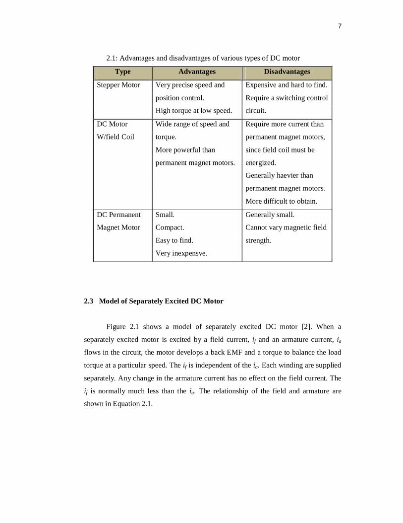
There are several types of DC motors that are available. Their advantages,
disadvantages and other basic information are list below in the Table 2.1 [1].
7
2.1: Advantages and disadvantages of various types of DC motor
Type Advantages Disadvantages
Stepper Motor Very precise speed and Expensive and hard to find.
position control. Require a switching control
High torque at low speed. circuit.
DC Motor Wide range of speed and Require more current than
W/field Coil torque. permanent magnet motors,
More powerful than since field coil must be
permanent magnet motors. energized.
Generally haevier than
permanent magnet motors.
More difficult to obtain.
DC Permanent Small. Generally small.
Magnet Motor Compact. Cannot vary magnetic field
Easy to find. strength.
Very inexpensve.
2.3 Model of Separately Excited DC Motor
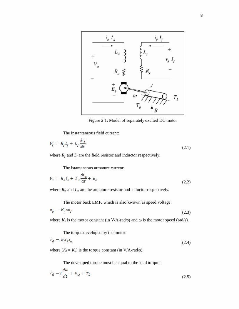
Figure 2.1 shows a model of separately excited DC motor [2]. When a
separately excited motor is excited by a field current, if and an armature current, ia
flows in the circuit, the motor develops a back EMF and a torque to balance the load
torque at a particular speed. The if is independent of the ia. Each winding are supplied
separately. Any change in the armature current has no effect on the field current. The
if is normally much less than the ia. The relationship of the field and armature are
shown in Equation 2.1.
8
Figure 2.1: Model of separately excited DC motor
The instantaneous field current:
(2.1)
where Rf and Lf are the field resistor and inductor respectively.
The istantaneous armature current:
(2.2)
where Ra and La are the armature resistor and inductor respectively.
The motor back EMF, which is also kwown as speed voltage:
(2.3)
where Kv is the motor constant (in V/A-rad/s) and ω is the motor speed (rad/s).
The torque developed by the motor:
(2.4)
where (Kt = Kv) is the torque constant (in V/A-rad/s).
The developed torque must be equal to the load torque:
(2.5)
9
where B = viscous friction constant, N·m/rad/s
TL = load torque, N·m
J = inertia of the motor, kg·m2
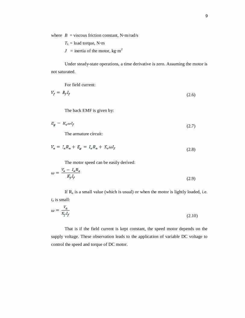
Under steady-state operations, a time derivative is zero. Assuming the motor is
not saturated.
For field current:
(2.6)
The back EMF is given by:
(2.7)
The armature circuit:
(2.8)
The motor speed can be easily derived:
(2.9)
If Ra is a small value (which is usual) or when the motor is lightly loaded, i.e.
ia is small:
(2.10)
That is if the field current is kept constant, the speed motor depends on the
supply voltage. These observation leads to the application of variable DC voltage to
control the speed and torque of DC motor.
10
2.4 Speed Control DC Motor Using Microcontroller
The electric drive systems used in industrial applications are increasingly
required to meet higher performance and reliability requirements. The DC motor is an
attractive place of equipment in many industrial applications requiring variable speed
and load characteristics due to its ease of controllability. Microcontrollers provide a
suitable means of meeting these needs [3]. Certainly, part of the recent activity on
microcontrollers can be ascribed to their newness and challenge. In this project use
microcontroller as controller for the speed controller use PIC.
Another system that uses a microprocessor is reported in the work is
reported in journal a brief description the system is as follow: The microprocessor
computes the actual speed of the motor by sensing the terminal voltage and the
current, it then compares the actual speed of the motor with the reference speed and
generates a suitable control signal which is fed into triggering unit [3].
A simple form of speed control is achieved through a variable potentiometer
for a manually controlled system; the operator mentally compares the actual speed to
a desired speed and sets the potentiometer accordingly. A simple form of speed
control is achieved through a variable potentiometer for a manually controlled system;
the operator mentally compares the actual speed to a desired speed and sets the
potentiometer accordingly. By comparing the speed in revolution per seconds (rps)
updated on the CRT screen each second to a desired speed, he/she corrects the current
speed by rotating the potentiometer clockwise to increase or counterclockwise to
reduce, the speed [4].