mohd hanafi bin sulaiman
TRANSCRIPT
8/10/2019 Mohd Hanafi Bin Sulaiman
http://slidepdf.com/reader/full/mohd-hanafi-bin-sulaiman 1/24
GAS DEHYDRATION USING GLYCOL SOLUTION IN ABSORPTION
AND ADSORPTION UNIT
MOHD HANAFI B SULAIMAN
UNIVERSITI MALAYSIA PAHANG
8/10/2019 Mohd Hanafi Bin Sulaiman
http://slidepdf.com/reader/full/mohd-hanafi-bin-sulaiman 2/24
GAS DEHYDRATION USING GLYCOL SOLUTION IN
ABSORPTION AND ADSORPTION UNIT
MOHD HANAFI BIN SULAIMAN
Submitted to the Faculty of Chemical & Natural Resources Engineering
in partial fulfillment of the requirements for the degree of Bachelor of
Chemical Engineering (Gas Technology)
Faculty of Chemical & Natural Resources Engineering
University Malaysia Pahang
APRIL 2009
8/10/2019 Mohd Hanafi Bin Sulaiman
http://slidepdf.com/reader/full/mohd-hanafi-bin-sulaiman 3/24
v
ABSTRACT
Gas dehydration is widely used in natural gas treatment plant as a common
process, because water and hydrocarbons can form hydrates, which may block valve and
pipelines. Water also can cause corrosion in the gas contain acid components. Until
today, among the most popular dehydration technology is either absorption or
adsorption process. In this research, a novel study on gas dehydration a combination of
absorption and adsorption process, where tri-ethylene glycol (TEG) and silica gel are
absorbent and adsorbent respectively. A laboratory absorption-adsorption unit is studied
in terms of natural gas (methane) flow rate and operating temperature to the percentage
of water removal. The experimental work started at room temperature by controlling thevalve of methane flow rate at 2.5 m
3 /hr initially and then allows the gas through the
absorption-adsorption unit. Meanwhile, tri-ethylene glycol (TEG) flows at 120 L/hr
from a circulation pump. Experiment was repeated with different methane flow rates
and different operating temperature in the range of 30oC until 50
oC. Experimental
results showed that, increasing of methane flow rate causes increasing of water removal
while increasing of operating temperature give a result of decreasing of water removal.
Thus, in analyzing the gas dehydration efficiency, in an absorption-adsorption unit,
parameters such as gas (methane) flow rate and operating temperature are among to be
considered for a reliability and economic benefit.
8/10/2019 Mohd Hanafi Bin Sulaiman
http://slidepdf.com/reader/full/mohd-hanafi-bin-sulaiman 4/24
vi
ABSTRAK
Penyahhidratan gas adalah digunakan secara meluas dalam loji rawatan gas asliseperti satu proses biasa, kerana air dan hidrokarbon akan membentuk hidrat, yang
mana akan menghalang injap dan talian paip. Air juga boleh menyebabkan karatan di
dalam gas yang mana mengandungi komponen gas asid. Sehingga hari ini, antara
teknologi penyahhidratan paling popular ialah penyerapan dan penjerapan dengan cecair
tri etilena glikol (TEG). Dalam satu kajian, penyahhidratan gas menggunakan gabungan
antara process penyerapan dan penjerapan, di mana tri etilena glikol (TEG) dan gel
silica masing-masing adalah pengisap. Dalam kajian ini, makmal unit penyerapan dan
penjerapan yang dipelajari lebih tertumpu pada peratusan bagi penyingkiran air
mengikut kadar aliran gas metana dan suhu kendalian. Kerja experimen itu bermula
pada suhu bilik di mana dengan mengawal injap kadar aliran metana pada 2.5 m 3 / hr
pada mulanya dan kemudian membenarkan gas itu melalui unit penyerapan dan
penjerapan. Manakala, tri etilena glikol sedang mengalir pada 120 L / hr dengan
menggunakan pam edaran. Eksperimen ini telah diulang dengan kadar aliran metana
yang berbeza dan suhu kendalian berbeza dalam julat 30oC hingga 50
oC. Di dalam
keputusan experiment, didapati bahawa kenaikan kadar aliran gas metana menyebabkan
pertambahan peratus air yang disingkirkan sementara itu kenaikan suhu kendalian
menyebabkan penurunan peratusan air yang disingkirkan. Oleh itu, dalam menganalisa
kecekapan penyahhidratan gas, dalam unit penyerapan dan penjerapan, parameter
seperti kadar aliran gas asli (metana) dan suhu pengendalian adalah antara yang perlu
dipertimbangkan untuk keblehpercayaan dan manfaat ekonomi.
8/10/2019 Mohd Hanafi Bin Sulaiman
http://slidepdf.com/reader/full/mohd-hanafi-bin-sulaiman 5/24
vii
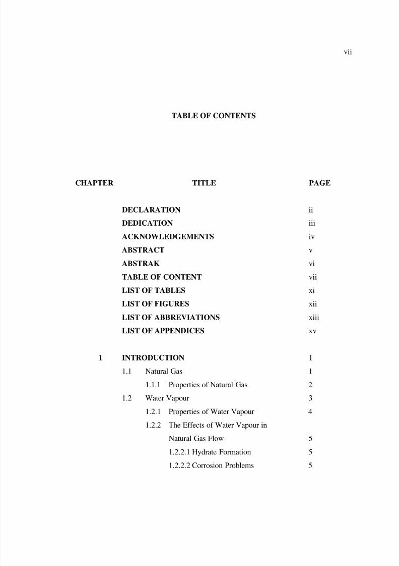
TABLE OF CONTENTS
CHAPTER TITLE PAGE
DECLARATION ii
DEDICATION iii
ACKNOWLEDGEMENTS iv
ABSTRACT v
ABSTRAK vi
TABLE OF CONTENT vii
LIST OF TABLES xi
LIST OF FIGURES xii
LIST OF ABBREVIATIONS xiii
LIST OF APPENDICES xv
1 INTRODUCTION 1
1.1 Natural Gas 1
1.1.1 Properties of Natural Gas 2
1.2
Water Vapour 3
1.2.1
Properties of Water Vapour 4
1.2.2
The Effects of Water Vapour in
Natural Gas Flow 5
1.2.2.1 Hydrate Formation 5
1.2.2.2 Corrosion Problems 5
8/10/2019 Mohd Hanafi Bin Sulaiman
http://slidepdf.com/reader/full/mohd-hanafi-bin-sulaiman 6/24
viii
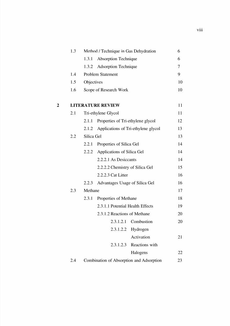
1.3 Method / Technique in Gas Dehydration 6
1.3.1
Absorption Technique 6
1.3.2
Adsorption Technique 7
1.4
Problem Statement 9
1.5 Objectives 10
1.6 Scope of Research Work 10
2 LITERATURE REVIEW 11
2.1
Tri-ethylene Glycol 112.1.1 Properties of Tri-ethylene glycol 12
2.1.2 Applications of Tri-ethylene glycol 13
2.2 Silica Gel 13
2.2.1
Properties of Silica Gel 14
2.2.2
Applications of Silica Gel 14
2.2.2.1
As Desiccants 14
2.2.2.2 Chemistry of Silica Gel 15
2.2.2.3 Cat Litter 16
2.2.3 Advantages Usage of Silica Gel 16
2.3
Methane 17
2.3.1
Properties of Methane 18
2.3.1.1 Potential Health Effects 19
2.3.1.2 Reactions of Methane 20
2.3.1.2.1 Combustion 20
2.3.1.2.2
Hydrogen
Activation 21
2.3.1.2.3
Reactions with
Halogens 22
2.4 Combination of Absorption and Adsorption 23
8/10/2019 Mohd Hanafi Bin Sulaiman
http://slidepdf.com/reader/full/mohd-hanafi-bin-sulaiman 7/24
ix
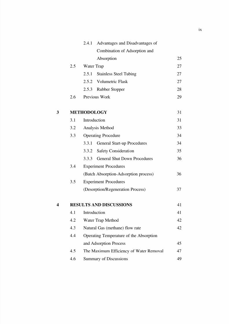
2.4.1 Advantages and Disadvantages of
Combination of Adsorption and
Absorption 25
2.5
Water Trap 27
2.5.1
Stainless Steel Tubing 27
2.5.2 Volumetric Flask 27
2.5.3 Rubber Stopper 28
2.6 Previous Work 29
3
METHODOLOGY 31 3.1 Introduction 31
3.2 Analysis Method 33
3.3 Operating Procedure 34
3.3.1
General Start-up Procedures 34
3.3.2
Safety Consideration 35
3.3.3
General Shut Down Procedures 36
3.4 Experiment Procedures
(Batch Absorption-Adsorption process) 36
3.5 Experiment Procedures
(Desorption/Regeneration Process) 37
4 RESULTS AND DISCUSSIONS 41
4.1 Introduction 41
4.2 Water Trap Method 42
4.3
Natural Gas (methane) flow rate 42
4.4
Operating Temperature of the Absorption
and Adsorption Process 45
4.5 The Maximum Efficiency of Water Removal 47
4.6 Summary of Discussions 49

8/10/2019 Mohd Hanafi Bin Sulaiman
http://slidepdf.com/reader/full/mohd-hanafi-bin-sulaiman 8/24
x
5 CONCLUSIONS AND RECOMMENDATIONS 51
5.1 Introduction 51
5.2
Conclusions 52
5.3
Recommendations 54
REFERENCES 55
Appendices A – F 59 - 66
8/10/2019 Mohd Hanafi Bin Sulaiman
http://slidepdf.com/reader/full/mohd-hanafi-bin-sulaiman 9/24
xi
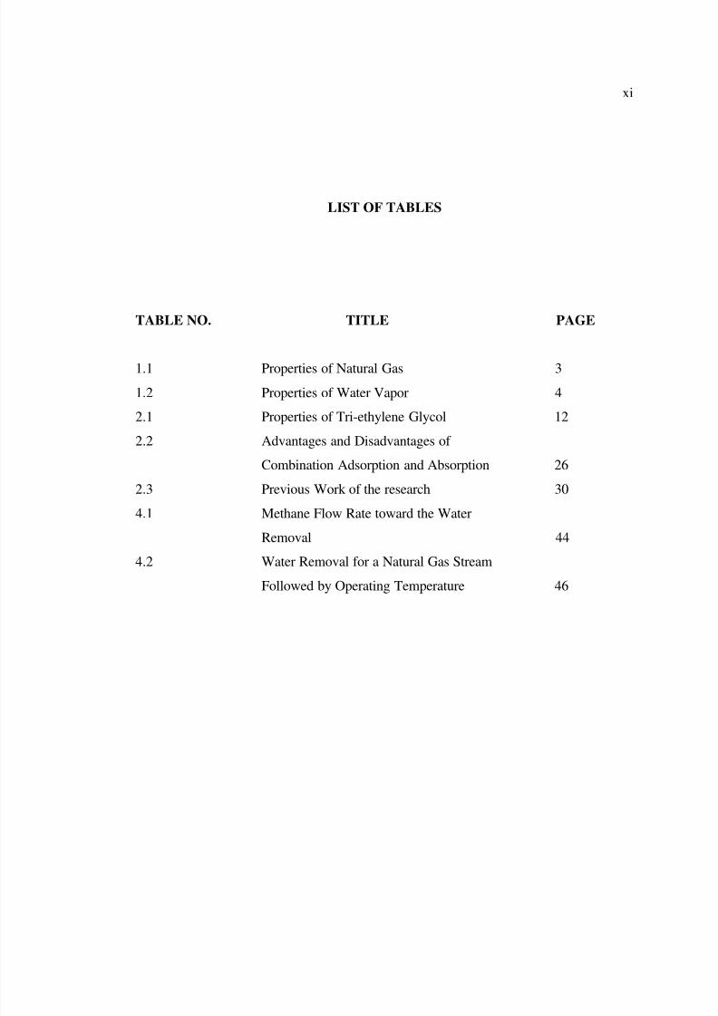
LIST OF TABLES
TABLE NO. TITLE PAGE
1.1
Properties of Natural Gas 3
1.2 Properties of Water Vapor 4
2.1 Properties of Tri-ethylene Glycol 12
2.2 Advantages and Disadvantages of
Combination Adsorption and Absorption 26
2.3
Previous Work of the research 30
4.1 Methane Flow Rate toward the Water
Removal 44
4.2 Water Removal for a Natural Gas Stream
Followed by Operating Temperature 46
8/10/2019 Mohd Hanafi Bin Sulaiman
http://slidepdf.com/reader/full/mohd-hanafi-bin-sulaiman 10/24
xii
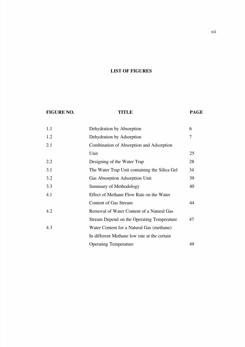
LIST OF FIGURES
FIGURE NO. TITLE PAGE
1.1 Dehydration by Absorption 6
1.2 Dehydration by Adsorption 7
2.1 Combination of Absorption and Adsorption
Unit 25
2.2
Designing of the Water Trap 28
3.1
The Water Trap Unit containing the Silica Gel 34
3.2 Gas Absorption Adsorption Unit 39
3.3 Summary of Methodology 40
4.1 Effect of Methane Flow Rate on the Water
Content of Gas Stream 44
4.2
Removal of Water Content of a Natural Gas
Stream Depend on the Operating Temperature 47
4.3 Water Content for a Natural Gas (methane)
In different Methane low rate at the certain
Operating Temperature 49
8/10/2019 Mohd Hanafi Bin Sulaiman
http://slidepdf.com/reader/full/mohd-hanafi-bin-sulaiman 11/24
xiii
LIST OF ABBREVIATION
CH4 - Methane
C2H6 - EthaneC3H8 - Propane
C4H10 - Butane
C5H12 - Pentane
CO2 - Carbon Dioxide
N - Nitrogen
He - Helium
H2S - Hydrogen Sulfide
CV - Calorific Value
PC - Critical Pressure
T4EG - Tetra-ethylene Glycol
TEG - Tri-ethylene Glycol
DEG - Di-ethylene Glycol
EG - Ethylene glycol
M-SG - Metals Silica Gel
C18 - Hydrophobic group
LNG - Liquid Natural Gas
HCHO - Formaldehyde
HCO - Formyl Radical
CO - Carbon Monoxide
H2O - Water
H2 - Hydrogen
8/10/2019 Mohd Hanafi Bin Sulaiman
http://slidepdf.com/reader/full/mohd-hanafi-bin-sulaiman 12/24
xiv
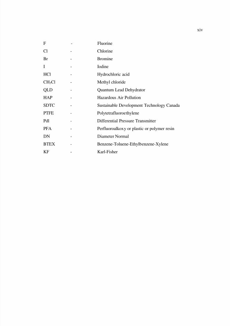
F - Fluorine
Cl - Chlorine
Br - Bromine
I - Iodine
HCl - Hydrochloric acid
CH3Cl - Methyl chloride
QLD - Quantum Lead Dehydrator
HAP - Hazardous Air Pollution
SDTC - Sustainable Development Technology Canada
PTFE - PolytetrafluoroethylenePdl - Differential Pressure Transmitter
PFA - Perfluoroalkoxy or plastic or polymer resin
DN - Diameter Normal
BTEX - Benzene-Toluene-Ethylbenzene-Xylene
KF - Karl-Fisher
8/10/2019 Mohd Hanafi Bin Sulaiman
http://slidepdf.com/reader/full/mohd-hanafi-bin-sulaiman 13/24
xv
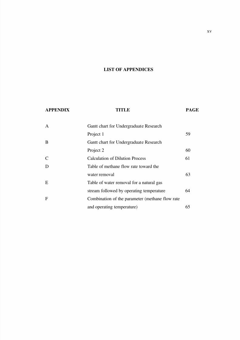
LIST OF APPENDICES
APPENDIX TITLE PAGE
A Gantt chart for Undergraduate Research
Project 1 59
B Gantt chart for Undergraduate Research
Project 2 60
C Calculation of Dilution Process 61
D Table of methane flow rate toward the
water removal 63
E Table of water removal for a natural gas
stream followed by operating temperature 64
F Combination of the parameter (methane flow rate
and operating temperature) 65
8/10/2019 Mohd Hanafi Bin Sulaiman
http://slidepdf.com/reader/full/mohd-hanafi-bin-sulaiman 14/24
1
CHAPTER 1
INTRODUCTION
1.1 Natural Gas
Millions of years ago, the remains of plants and animals decayed and built up in
thick layers. This decayed matter from plants and animals is called organic material -
which was once alive. Over time, the mud and soil changed to rock, covered the organic
material and trapped it beneath the rock. Pressure and heat changed some of this
organic material into coal, some into oil (petroleum), and some into natural gas - tiny
bubbles of odorless gas. The main ingredient in natural gas is methane, a gas (or
compound) composed of one carbon atom and four hydrogen atoms.
Natural gas is a gaseous fossil fuel consisting primarily of methane but including
significant quantities of ethane, propane, butane, and pentane – which need to be
removed before the gas is considered clean fuel to be used —as well as water, carbon
dioxide, nitrogen, helium and hydrogen sulfide.
8/10/2019 Mohd Hanafi Bin Sulaiman
http://slidepdf.com/reader/full/mohd-hanafi-bin-sulaiman 15/24
2
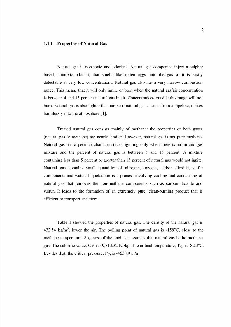
1.1.1 Properties of Natural Gas
Natural gas is non-toxic and odorless. Natural gas companies inject a sulpher
based, nontoxic odorant, that smells like rotten eggs, into the gas so it is easily
detectable at very low concentrations. Natural gas also has a very narrow combustion
range. This means that it will only ignite or burn when the natural gas/air concentration
is between 4 and 15 percent natural gas in air. Concentrations outside this range will not
burn. Natural gas is also lighter than air, so if natural gas escapes from a pipeline, it rises
harmlessly into the atmosphere [1].
Treated natural gas consists mainly of methane: the properties of both gases
(natural gas & methane) are nearly similar. However, natural gas is not pure methane.
Natural gas has a peculiar characteristic of igniting only when there is an air-and-gas
mixture and the percent of natural gas is between 5 and 15 percent. A mixture
containing less than 5 percent or greater than 15 percent of natural gas would not ignite.
Natural gas contains small quantities of nitrogen, oxygen, carbon dioxide, sulfur
components and water. Liquefaction is a process involving cooling and condensing of
natural gas that removes the non-methane components such as carbon dioxide and
sulfur. It leads to the formation of an extremely pure, clean-burning product that is
efficient to transport and store.
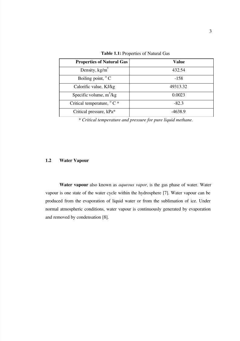
Table 1 showed the properties of natural gas. The density of the natural gas is
432.54 kg/m3, lower the air. The boiling point of natural gas is -158oC, close to the
methane temperature. So, most of the engineer assumes that natural gas is the methane
gas. The calorific value, CV is 49,313.32 KJ/kg. The critical temperature, TC, is -82.3oC.
Besides that, the critical pressure, PC, is -4638.9 kPa
8/10/2019 Mohd Hanafi Bin Sulaiman
http://slidepdf.com/reader/full/mohd-hanafi-bin-sulaiman 16/24
3
Table 1.1: Properties of Natural Gas
Properties of Natural Gas Value
Density, kg/m 432.54
Boiling point,o C -158
Calorific value, KJ/kg 49313.32
Specific volume, m /kg 0.0023
Critical temperature, o C * -82.3
Critical pressure, kPa* -4638.9
* Critical temperature and pressure for pure liquid methane.
1.2 Water Vapour
Water vapour also known as aqueous vapor , is the gas phase of water. Water
vapour is one state of the water cycle within the hydrosphere [7]. Water vapour can be
produced from the evaporation of liquid water or from the sublimation of ice. Under
normal atmospheric conditions, water vapour is continuously generated by evaporation
and removed by condensation [8].
8/10/2019 Mohd Hanafi Bin Sulaiman
http://slidepdf.com/reader/full/mohd-hanafi-bin-sulaiman 17/24
4
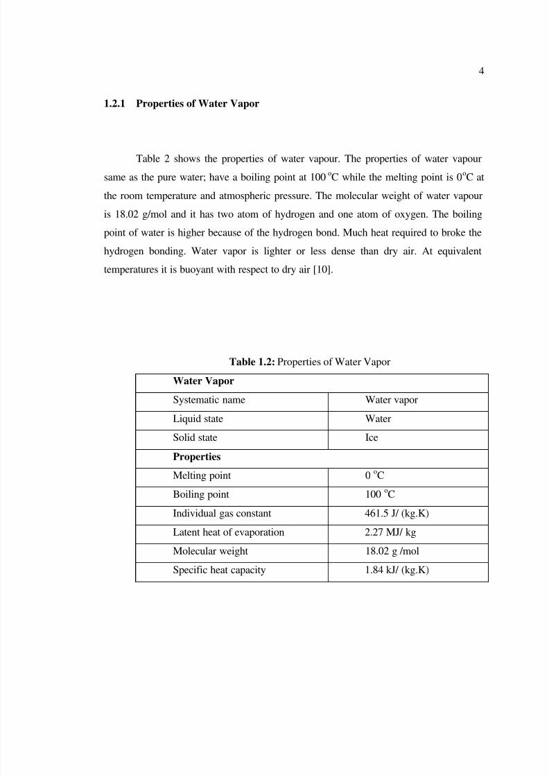
1.2.1 Properties of Water Vapor
Table 2 shows the properties of water vapour. The properties of water vapour
same as the pure water; have a boiling point at 100oC while the melting point is 0
oC at
the room temperature and atmospheric pressure. The molecular weight of water vapour
is 18.02 g/mol and it has two atom of hydrogen and one atom of oxygen. The boiling
point of water is higher because of the hydrogen bond. Much heat required to broke the
hydrogen bonding. Water vapor is lighter or less dense than dry air. At equivalent
temperatures it is buoyant with respect to dry air [10].
Table 1.2: Properties of Water Vapor
Water Vapor
Systematic name Water vapor
Liquid state Water
Solid state Ice
Properties
Melting point 0oC
Boiling point 100oC
Individual gas constant 461.5 J/ (kg.K)
Latent heat of evaporation 2.27 MJ/ kg
Molecular weight 18.02 g /mol
Specific heat capacity 1.84 kJ/ (kg.K)
8/10/2019 Mohd Hanafi Bin Sulaiman
http://slidepdf.com/reader/full/mohd-hanafi-bin-sulaiman 18/24
5
1.2.2 The Effects of Water Vapour in Natural Gas Flow
1.2.2.1 Hydrate Formation
Hydrates are solids formed by the physical combination of water and other small
molecules of hydrocarbons [6]. They are icy hydrocarbon compounds of about 10%
hydrocarbons and 90% water. Hydrates grow as crystals and can build up in orifice
plates, valves and other area not subjected to full flow. Thus, hydrates can plug lines and
retard the flow of gaseous hydrocarbon streams. The primary conditions promoting
hydration formation are the following the certain characteristic. The characteristic of
hydration formation are gas must be at or below its water (dew) point with “free” water
present and it also occur in low temperature and high pressure.
1.2.2.1 Corrosion Problems
Corrosion often occurs when liquid water is present along with acidic gases,
which tend to dissolve and disassociate in the water phase, forming acidic solutions. Theacidic solutions can be extremely corrosive, especially for carbon steel, which is
typically used in the construction of most hydrocarbon processing facilities.
8/10/2019 Mohd Hanafi Bin Sulaiman
http://slidepdf.com/reader/full/mohd-hanafi-bin-sulaiman 19/24
6
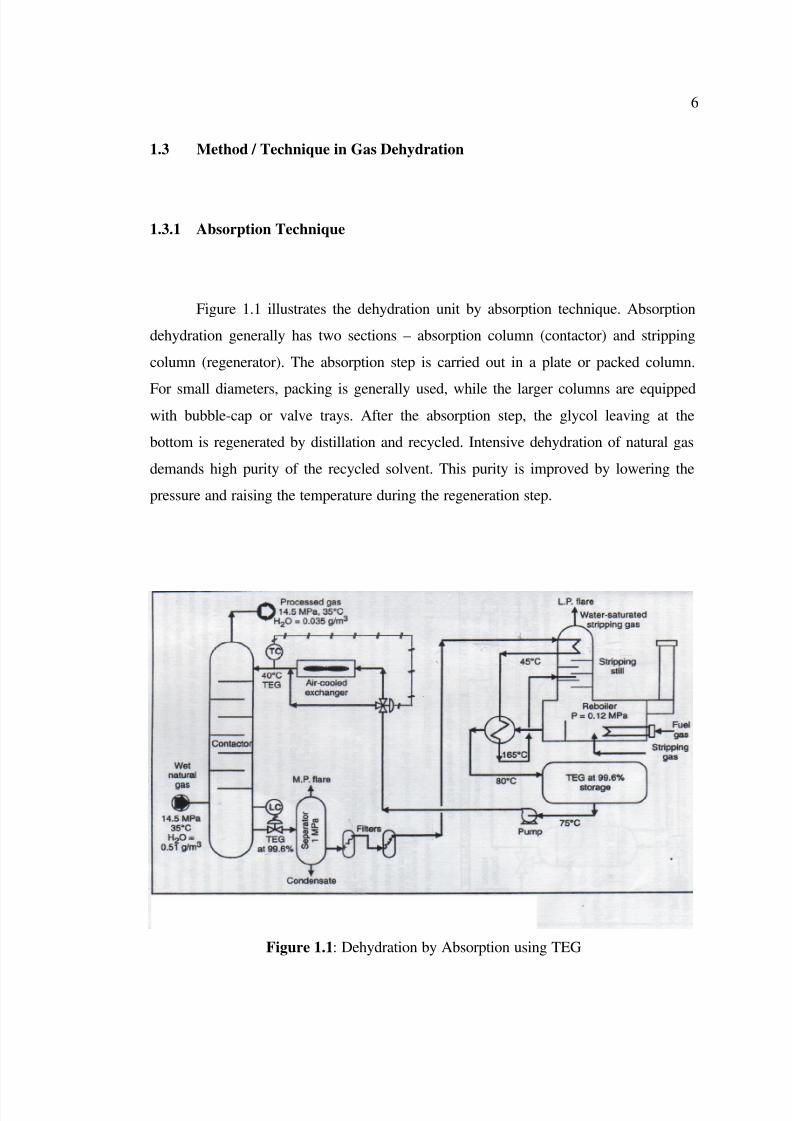
1.3 Method / Technique in Gas Dehydration
1.3.1 Absorption Technique
Figure 1.1 illustrates the dehydration unit by absorption technique. Absorption
dehydration generally has two sections – absorption column (contactor) and stripping
column (regenerator). The absorption step is carried out in a plate or packed column.
For small diameters, packing is generally used, while the larger columns are equippedwith bubble-cap or valve trays. After the absorption step, the glycol leaving at the
bottom is regenerated by distillation and recycled. Intensive dehydration of natural gas
demands high purity of the recycled solvent. This purity is improved by lowering the
pressure and raising the temperature during the regeneration step.
Figure 1.1: Dehydration by Absorption using TEG
8/10/2019 Mohd Hanafi Bin Sulaiman
http://slidepdf.com/reader/full/mohd-hanafi-bin-sulaiman 20/24
7
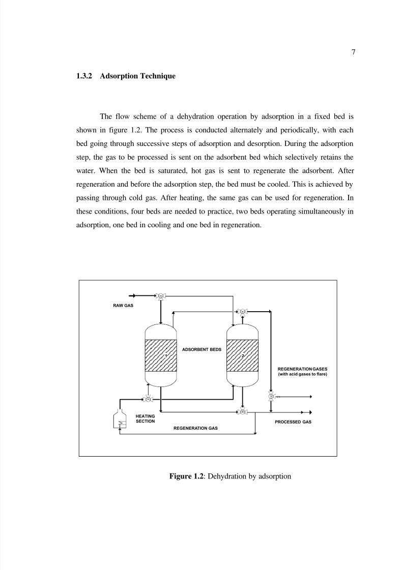
1.3.2 Adsorption Technique
The flow scheme of a dehydration operation by adsorption in a fixed bed is
shown in figure 1.2. The process is conducted alternately and periodically, with each
bed going through successive steps of adsorption and desorption. During the adsorption
step, the gas to be processed is sent on the adsorbent bed which selectively retains the
water. When the bed is saturated, hot gas is sent to regenerate the adsorbent. After
regeneration and before the adsorption step, the bed must be cooled. This is achieved by
passing through cold gas. After heating, the same gas can be used for regeneration. Inthese conditions, four beds are needed to practice, two beds operating simultaneously in
adsorption, one bed in cooling and one bed in regeneration.
ADSORBENT BEDS
V-3
2
HEATINGSECTION
1
RAW GAS
REGENERATION GASES(with acid gases to flare)
PROCESSED GAS
REGENERATION GAS
Figure 1.2: Dehydration by adsorption
8/10/2019 Mohd Hanafi Bin Sulaiman
http://slidepdf.com/reader/full/mohd-hanafi-bin-sulaiman 21/24
8
The most widely used adsorbents today are the following;
Activated carbon
Activated carbon is high degree of microporosity, one gram of activated carbon
has a surface area of approximately 500 m². It also higher density provides greater
volume activity and normally indicates better quality activated carbon. Activated carbon
as an adsorbent at low pressure and subsequent desorption by heating.
Activated alumina
Activated Alumina is achieving a low residual-water content of about 1 ppm vol.
The heavy hydrocarbons are adsorbed but cannot desorbed during regeneration.
Therefore, if such heavy hydrocarbons are present in the gas, they have to be removed
before the adsorption step.
Silica gel
The water content of the gas processed by adsorption on silica gel is about 10
ppm vol. Silica gel is easily regenerated at a temperature between 120 and 200 oC. It
adsorbs the hydrocarbons, where are then desorbed during regeneration. Therefore, it
can be used to separate simultaneously the water and the condensate fraction of the gas
processed, provided a number of precautions are observed.
8/10/2019 Mohd Hanafi Bin Sulaiman
http://slidepdf.com/reader/full/mohd-hanafi-bin-sulaiman 22/24
9
Molecular sieves (Zeolites)
Molecular sieves is a silicoaluminates, in which the crystal sturcture forms
cavities making up a microporous network on a molecular scale. Molecular sieves are
used to obtain very low water levels in the processed gas (down to 0.03 ppm vol), but
the technique is relatively expensive – the adsorbent is an expensive material that must
be replaced every three years. Thus for structure A sieves, depending on the
compensation cation, the size of the access cavities maybe about 3A (3A sieves), 4A
(4A sieves) or 5A (5A sieves).
1.4 Problem Statement
The glycol dehydration unit is extensively used in the oil and gas industry toproduce dehydrated gas. It also used in natural gas treatment plant as a common process,
because water and hydrocarbon can form hydrates, which may block valves and
pipelines.
Basically, without understanding and properly determining the parameters which
affect analyze the removal of water vapours, it is unsufficient to the efficient gas
dehydration process. Hence, this research is going to study among the important
parameter which are natural gas or this case was referred to methane flow rate and
operating temperature.The two parameters were manipulated to get the optimum value
of removing water vapour.
8/10/2019 Mohd Hanafi Bin Sulaiman
http://slidepdf.com/reader/full/mohd-hanafi-bin-sulaiman 23/24
10
1.5 Objectives
To analyze the performance of adsorption & absorption unit in removing water
vapor by emphasizing important parameter such as Natural Gas (methane) flow rate and
operating temperature.
1.6 Scope of Research Work
This research focuses on two main scopes which are:
1)
The study for a combination of absorption and adsorption processes in an
absorption-adsorption unit for a water removal in natural gas flow.
2) To analyze its two important parameter such as gas flow rate and operating
temperature.
8/10/2019 Mohd Hanafi Bin Sulaiman
http://slidepdf.com/reader/full/mohd-hanafi-bin-sulaiman 24/24