uthm institutional repository - 3 0000 00110174...
TRANSCRIPT

3 0000 00110174 4

PSZ 19: 16 (pind. l/97)
UNIVERSITI TEKNOLOGI MALAYSIA
BORANG PENGESAHAN STATUS TESIS.
JUDUL: MICROSTRIP SIERPINSKI CARPET ANTENNA DESIGN
SESI PENGAJlAN: 2004/2005
Saya NOORSAJ.[ZA BI ABDlll.I.AH
(HURUF BESAR)
mengaku membenarkan tesis (PSM/SllIjana/Delaer Falsafab)* ini disimpan di Perpustakaan Universiti Telmologi Malaysia dengan syarat-syarat kegunaan seperti berikut:
I. Tesis adalah hakmilik Universiti Teknologi Malaysia 2. Perpustakaan Universiti Teknologi Malaysia dibenarkan membuat salinan untuk
tujuan pengajian sahaja 3. Perpustakaan dibenarkan membuat salinan tesis ini sabagai pertukaran antara institusi
pengajian tinggi. 4. **Sila tandakan (.f )
D SULIT (Mengandungi maklumat yang berdllljah keselamatan atau kepentingan Malaysia seperti yang termaktub di dalam (AKT A RAHSIA RASMI 1972)
D TERHAD (Mengandungi maklumat TERHAD yang telah ditentukan oleh organisasilbadan di mana penyelidikan dijalankan)
D TIDAK TERHAD
2t: . .....
~oleh
(T ANDAT ANGAN PENULIS) (T ANDAT ANGAN PENYELIA)
Alamat tetap: Nama Penyelia:
KG. DANGGOL BELIMBING. JALAN JENUN. 06700. PENDANG. KEDAB.
DR. MOHAMAD KAMAL DINA. RAHIM
Tarikh: 4 APRIL 2005 Tarikh: 4 APRIL 2005
CATATAN: • Potong yang tidak. berkenaan. •• Jika tesis ini SULIT atau TERHAD, sila lampirkan sural daripada pihak
berkuasalorganisasi berkenaan dengan menyatakan sekali sebab dan tempoh tesis ini perlu dikelaskan sebagai SULIT atau TERHAD.
• Tesis dimaksudkan sebagai lesis bagi Ijazah Doktor Falsafah dan Saljana secara penyeJidikan, atau disertasi bagi pengajian secara kerja kursus dan penyeJidikan, atau Laporan Projek Sarjana Muda (PSM).
"I hereby declared that I have read this thesis and in my opinion this project
is fully adequate in scope and quality, as dissertation for
Master of Engineering ( Electical-Electronics & Telecommunications)"
Signature
Name : DR. MOHAMAD KAMAL BIN A. RAHIM
Date : 4th of APRIL 2005
MICROSTRIP SIERPINSKI CARPET ANTENNA DESIGN
NOORSALIZA BT ABDULLAH
A thesis submitted in fulfillment
of the requirement for the award of the
Degree of Master of Engineering
( Electrical-Electronics & Telecommunications)
Faculty of Electrical Engineering
Universiti Teknologi Malaysia
MARCH, 2005

DECLARA TION
"It is hereby declared that the materials presented in this thesis are the results
of my own work except as cited as reference."
Signature
Name
Date
,Ylc' : NOORSALIZA BT ABDULLAH
: 4th of APRIL 2005
ii

111
To my beloved parents:
Thank you for giving me the chance to be what J can be.

ACKNOWLEDGEMENTS
I wish to express my thankfulness to my supervisor Dr Mohamad Kamal A
Rahim for his invaluable guidance, patience and support through the completion of
this project. I also would like to thanks En Mohammad Zoinol Abidin Abd Aziz for
his help on experimental testing.
lV
Finally, I would like to thank everyone that has been involved in this project
directly or indirectly for their help and contribution.

v
ABSTRACT
Low cost of fabrication and low profile features of microstrip antennas,
attract many researchers to investigate the perfonnance of this antenna in various
ways. Fractal antenna is a new member in the family of antennas. They have peculiar
properties that make them suitable for applications where wideband and multiband
are important parameters of the overall perfonnance. Fractal technology allowed us
to design miniature antennas and integrate multiple telecommunication services such
as cellular ( GSM 900 and GSM 1800 ), wireless LAN, GPS and hiperLAN2 into a
single device. Microstrip sierpinski carpet antenna and sierpinski carpet monopole
antenna are designed in this project. The main objective of this project is to design a
multiband antenna. The design involved simulations, fabrications and measurements.
Mathcad 2001 is used to obtain the size of the basic square patch antenna and
simulation was done using Micropatch v.2 and Microwave Office. The fabrication
and testing was done at Wireless Communication Centre (WCC). Wideband and
multiband operation was observed in sierpinski carpet monopole antenna.

V1
ABSTRAK
Ciri-ciri antena microjalur yang berprofil rendah dan kos fabrikasi yang
murah telah membuka laluan kepada para penyelidik untuk mengkaji prestasi antena
ini dalam pelbagai cara. Antena pecahan ini masih dikategorikan barn dalam antenna.
Antena pecahan ini mempunyai ciri-ciri khusus yang membolehkan ia digunakan
dalam aplikasi yang mana jalur lebar dan jalur banyak merupakan parameter yang
penting bagi menentukan prestasi keseluruhan. Tekoologi pecahan ini membenarkan
kita merekabentuk antena yang bersaiz kecil dan memuatkan pelbagai servis
telekomunikasi seperti GSM ( GSM 900 dan GSM 1800), wirelessLAN, GPS dan
hiperLAN2 didalam satu peranti sahaja Antena tampal pecahan mikrojalur dan
antena hamparan tegak direka dalam projek ini. Objektif utama projek ini adalah
untuk merekabentuk antena yang mempunyai banyak jalur frekuensi. Proses yang
terlibat dalam merekabentuk antena ini ialah simulasi, fabrikasi dan pengukuran.
Program Mathcad 2001 digunakan bagi mendapatkan saiz antena segiempat tampal
dan simulasi dilakukan menggunakan Micropatch v.2 dan Microwave Office.
Fabrikasi dan pengukuran dilakukan di makmal Pusat Perhubungan Tanpa Wayar
(WeC). Antena hamparan tegak dapat beroperasi dalam jalur lebar dan banyak
frekuensi.
CHAPTER
CHAPTER I
CHAPTER II
TABLE OF CONTENTS
TITLE
Declaration
Dedication
Acknowledgement
Abstract
Abstrak
Table of contents
List of Tables
List of Figures
List of Symbols
INTRODUCTION TO THE PROJECT
1.1 Project Background
1.2 Objective
1.3 Scope of Work
1.4 Dissertation Overview
ANTENNA THEORY
2.1 Introduction to Antenna
2.2 Antenna Properties
PAGE
ii
iii
iv
v
vi
vii
Xl
XII
xiv
1
1
2
3
3
5
5
6
VII
CHAPTER III
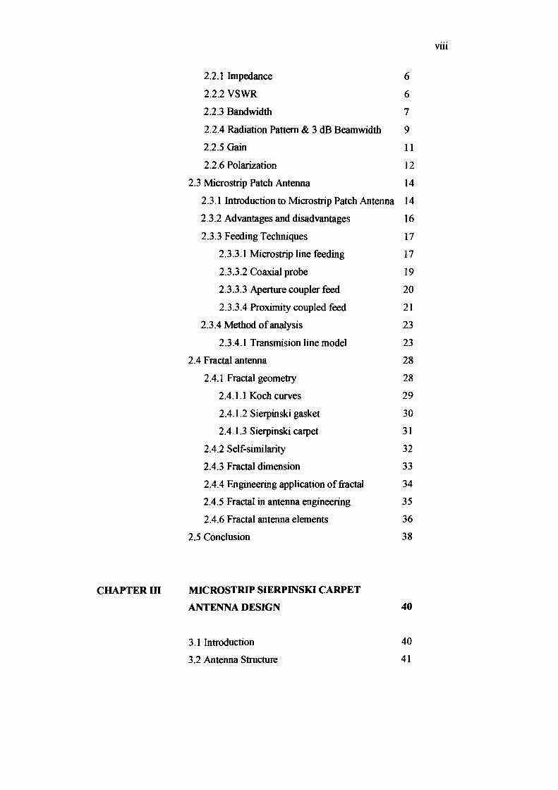
2.2.1 Impedance
2.2.2 VSWR
2.2.3 Bandwidth
2.2.4 Radiation Pattern & 3 dB Beamwidth
2.2.5 Gain
2.2.6 Polarization
2.3 Microstrip Patch Antenna
2.3.1 Introduction to Microstrip Patch Antenna
2.3.2 Advantages and disadvantages
2.3.3 Feeding Techniques
2.3.3.1 Microstrip line feeding
2.3.3.2 Coaxial probe
2.3.3.3 Aperture coupler feed
2.3.3.4 Proximity coupled feed
2.3.4 Method of analysis
2.3.4.1 Transmision line model
2.4 Fractal antenna
2.4.1 Fractal geometry
2.4.1.1 Koch curves
2.4.1.2 Sierpinski gasket
2.4.1.3 Sierpinski carpet
2.4.2 Self-similarity
2.4.3 Fractal dimension
2.4.4 Engineering application of fractal
2.4.5 Fractal in antenna engineering
2.4.6 Fractal antenna elements
2.5 Conclusion
MICROSTRIP SIERPINSKI CARPET
ANTENNA DESIGN
3.1 Introduction
3.2 Antenna Structure
6
6
7
9
11
12
14
14
16
17
17
19
20
21
23
23
28
28
29
30
31
32
33
34
35
36
38
40
40
41
Vlli
ix
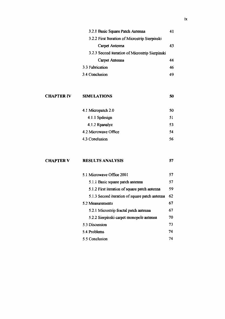
3.2.1 Basic Square Patch Antenna 41
3.2.2 First Iteration of Micros trip Sierpinski
Carpet Antenna 43
3.2.3 Second iteration of Micros trip Sierpinski
Carpet Antenna 44
3.3 Fabrication 46
3.4 Conclusion 49
CHAPTER IV SIMULATIONS 50
4.1 Micropatch 2.0 50
4.1.1 Spdesign 51
4.1.2 Rpanalyz 53
4.2 Microwave Office 54
4.3 Conclusion 56
CHAPTER V RESULTS ANALYSIS 57
5.1 Microwave Office 2001 57
5.1.1 Basic square patch antenna 57
5.1.2 First iteration of square patch antenna 59
5.1.3 Second iteration of square patch antenna 62
5.2 Measurements 67
5.2.1 Microstrip fractal patch antenna 67
5.2.2 Sierpinski carpet monopole antenna 70
5.3 Discussion 73
5.4 Problems 74
5.5 Conclusion 74
CHAPTER VI CONCLUSION AND RECOMMENDATIONS 75
6.1 Conclusions
6.2 Future works
REFERENCES
APPENDIX
Appendix A 1-A3
75
76
77
79
x
Xl
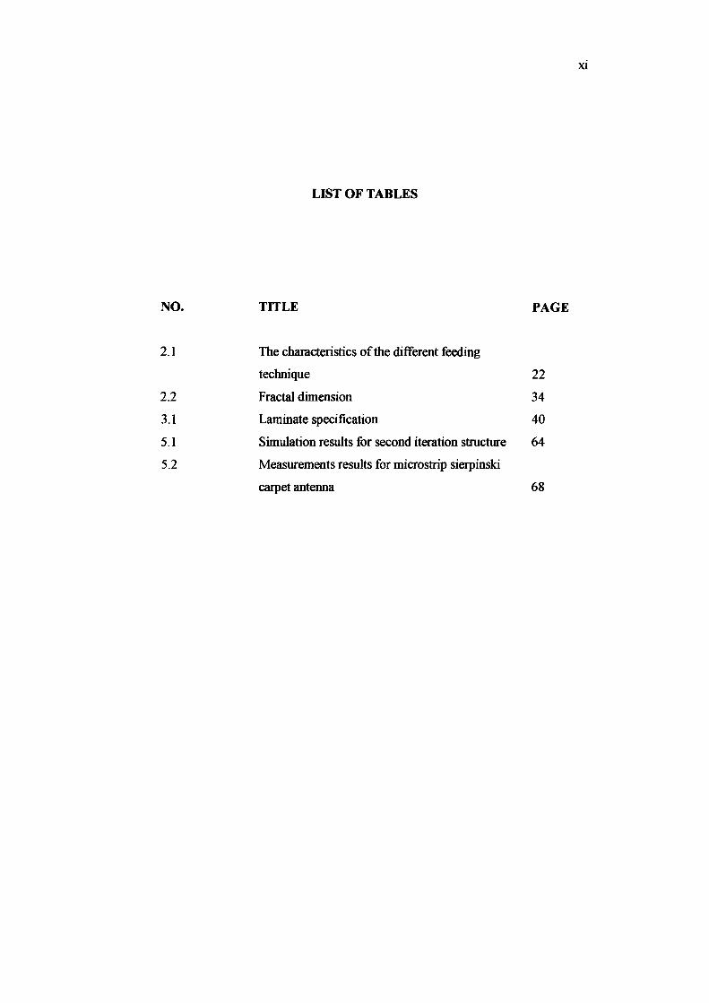
LIST OF TABLES
NO. TITLE PAGE
2.1 The characteristics of the different feeding
technique 22
2.2 Fractal dimension 34
3.1 Laminate specification 40
5.1 Simulation results for second iteration structure 64
5.2 Measurements results for microstrip sierpinski
carpet antenna 68
xii
LIST OF FIGURES
NO. TITLE PAGE
2.1 Frequency response for antenna 8
2.2 Radiation pattern and 3dB beam width 9
2.3 A rectangular patch antenna 15
2.4 Microstrip line feeding 18
2.5 Probe fed for rectangular patch antenna 19
2.6 Aperture coupled feed 20
2.7 Proximity coupled feed 22
2.8 Microstrip line 23
2.9 Electric field lines 23
2.10 Microstrip patch antenna 25
2.11 Top view of the antenna 26
2.12 Side view of the antenna 26
2.13 The first stages in construction of Koch curve 29
2.14 The first stages in construction of sierpinski gasket 30
2.15 The first stages in construction of sierpinski carpet 31
2.16 The self-similarity of sierpinski gasket 33
3.1 Square patch antenna 42
3.2 First iteration of sierpinski carpet fractal antenna 44
3.3 Second iteration of sierpinski carpet fractal antenna 46
3.4 Fabrication process from beginning 47
3.5 Microstrip fractal patch antenna 48
3.6 Sierpinski carpet monopole antenna 48
4.1 Design parameter in Micropatch 2.0 52
xiii
4.2 Optimization 52
4.3 Screen shot of Microwave Office 56
5.1 Square patch antenna layout 58
5.2 Return loss of square patch antenna 58
5.3 Polar plot for square patch antenna, frequency 1.82 GHz 59
5.4 First iteration antenna layout 60
5.5 Return loss for first iteration 60
5.6 Polar plot for first band, frequency 4.3 GHz 61
5.7 Polar plot for second band, frequency 5.8 GHz 62
5.8 Second iteration antenna layout 63
5.9 Return loss for second iteration 63
5.10 Polar plot for first band, frequency 4.15 GHz 64
5.11 Polar plot for second band, frequency 5.3 GHz 65
5.12 Polar plot for third band, frequency 6.6 GHz 65
5.13 Polar plot for fourth band, frequency 8.1 GHz 66
5.14 Polar plot for fifth band, frequency 9.25 GHz 66
5.15 Microstrip sierpinski carpet antenna 68
5.16 Return loss 68
5.17 E-plane for co-polar and cross-polar, frequency 2.59 GHz 69
5.18 E-plane for co-polar and cross-polar, frequency 5.2 GHz 70
5.19 Sierpinski carpet monopole antenna 71
5.20 Return loss for Sierpinski carpet monopole antenna 71
5.21 Polar plot for co-polar and cross-polar, frequency 2.73 GHz72
5.22 Polar plot for co-polar and cross-polar, frequency 4.29 GHz 72
5.23 Input return loss for measurement and simulation 73
BW
f
L
W
h
tan 0
V
G
&r
&elf
c
VSWR
CW
CCW
LIST OF SYMBOLS
Bandwidth
Frequency
Length of the Microstrip Patch Antenna
Width of the Microstrip Patch Antenna
Substrate thickness
Loss tangent of dielectric material
voltage
Gain
Relative Permittivity
Effective Relative Permittivity
Fringe factor
Velocity of electromagnetic waves in free space
Voltage standing Wave Ratio
Clock wise
Counter clock wise
xiv
CHAPTER I
INTRODUCTION
1.1 Project Background
Modem telecommunication systems require antennas with wider bandwidths
and smaUer dimensions than conventionally possible. This has initiated antenna
research in various directions, one of which is by using fractal shaped antenna
elements. In recent years several fractal geometries have been introduced for antenna
applications with varying degrees of success in improving antenna characteristics.
Some of these geometries have been particularly useful in reducing the size of the
antenna, while other designs aim at incorporating multi-band characteristics. Yet no
significant progress has been made in corroborating fractal properties of these
geometries with characteristics of antennas.
Several antenna configurations based on fractal geometries have been
reported in recent years. These are low profile antennas with moderate gain and can
be made operative at multiple frequency bands and hence are multi-functional. In this
work the multi-band (multifunctional) aspect of antenna designs are explored further
with special emphasis on identifYing fractal properties that impact antenna multi
band characteristics. To lay foundations for the understanding of the behavior of such
antennas, the nature of fractal geometries is explained first, before presenting the
status of literature on antennas using such geometries.
Fractal geometry allows us to design a miniature antenna and integrate
multiple telecommunication services into single device. One of the most relevant
trends for wireless devices is miniaturization. Miniaturization become important for
the next generation of antennas for wireless applications which have to integrate
multiple services such as cellular (GSM 900 and GSM 18(0), wireless LAN 2.4
GHz, GPS 1.575 GHz, radio and hiperLAN2 5.25GHz into one device such as
handsets, laptops and PDAs. In this situation, we need the smallest antenna to make
use of the available wireless service and for coverage of the different frequency
bands is made possible with multiple-band antenna design.
1.2 Objective
2
Objective of this project is to design and fabricate a multi band antenna using
sierpinski carpet fractal antenna and microstrip fractal antenna. Parameters that
influence antenna's performance in term of matching and bandwidth are studied to
achieve this objective. Design and fabrication processes are based on simulation
using Microwave Office.

1.3 Scope of Work
Scope of this project:-
i. Design and fabricate a sierpinski carpet fractal antenna and a
microstrip fractal antenna.
ll. Investigate the performance of the sierpinski carpet fractal antenna
and microstrip fractal antenna.
1.4 Disser1ation Overview
In this dissertation, several topics are covered and they are organized into six
chapters. This first chapter, the introduction to the project, gives an explanation of
the objective, scope of work and project background.
Chapter II begin with the description of antenna characteristics. This is
followed by discussion of relevant theory and literature review on the designed
antenna structures. Matching techniques and method of analysis are also presented.
Chapter III presents the antenna design procedure and the fabrication of the
designed antennas. This chapter discusses the design of basic microstrip square patch
antenna and microstrip fractal patch antenna.
Chapter IV presents brief description of software used in designing and
simulating the antenna structures. Some examples of the simulation results are
included.
3

Chapter V presents some results and analysis that obtained from simulation
and measurement.
Chapter VI presents the conclusions for this thesis. Some ideas for future
works of this project are suggested.
4
CHAPTER II
ANTENNA THEORY
2.1 Introduction to the antenna
Antenna is the device for radiating or receiving electromagnetic wave in free
space. The antenna is the interface between transmission line and free space.
Antenna passive is the reciprocal devices. It can be used for transmitting or receiving
signal. Antenna active is not the reciprocal devices.
Passive antenna has various shape and geometries such as wire antennas,
aperture antennas and printed antennas. Dipole antennas, loop antennas and helix
antennas are classified as wire antennas while hom antennas and slot antennas are
classified as aperture antennas. For printed antennas, there have patch antennas and
printed slot antennas. Patch antennas is being discuss further in this chapter.
2.2 Antenna Properties
To describe the performance of an antenna, definitions of various properties
are necessary. Some of the basic properties of antennas are discussed below.
2.2.1 Impedance
6
The input impedance of the antenna must identically match the characteristic
impedance of the transmission line in order to achieve maximum energy transfer
between a transmission line and an antenna. If the input impedance of the antenna
does not match with the characteristic impedance of the transmission line, a reflected
wave will be generated at the antenna teminal and travel back towards the energy
source. This reflection of energy results in a reduction in the overall system
efficiency. This loss in efficiency will occur if the antenna is used to transmit or
receive energy.
2.2.2 Voltage Standing Wave Ratio (VSWR)
VSWR is the ratio between the maximum voltage and the minimum voltage
along the transmission line. The equation ofVSWR is given by:
1+lr l VSWR=-II 1- r (2.1 )