representasi gaya dalam pada struktur balok sederhana
TRANSCRIPT
a home base to excellence
Representasi Gaya Dalam Pada Struktur balok sederhana
Pertemuan – 5 & 6
Mata Kuliah : Statika
Kode : CVL – 104
SKS : 3 SKS
a home base to excellence
• TIU :• Mahasiswa dapat menghitung gaya-gaya dalam momen, lintang dan
normal pada struktur statis tertentu
• TIK :• Mahasiswa dapat menganalisis gaya dalam momen, lintang dan netral
pada struktur balok sederhana
a home base to excellence
• Sub Pokok Bahasan :
• Gaya dalam momen
• Gaya dalam Lintang
• Gaya dalam Normal
a home base to excellence
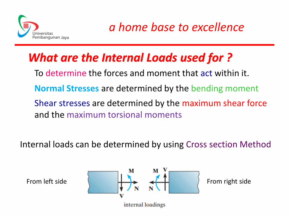
To determine the forces and moment that act within it.
Normal Stresses are determined by the bending moment
Shear stresses are determined by the maximum shear forceand the maximum torsional moments
Internal loads can be determined by using Cross section Method
What are the Internal Loads used for ?
From left side From right side
a home base to excellence
Internal Loading for Coplanar structure will consist :
• Normal/Axial Force ( N )
• Shear Force ( V / D )
• Bending Moment ( M )
a home base to excellence
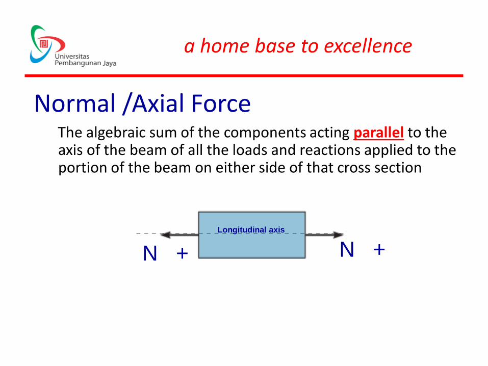
Normal /Axial ForceThe algebraic sum of the components acting parallel to the axis of the beam of all the loads and reactions applied to the portion of the beam on either side of that cross section
N +N +
Longitudinal axis
a home base to excellence
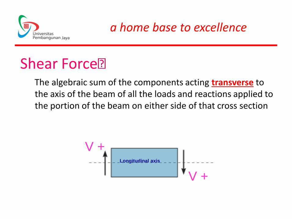
Shear ForceThe algebraic sum of the components acting transverse to the axis of the beam of all the loads and reactions applied to the portion of the beam on either side of that cross section
V +
V +Longitudinal axis
a home base to excellence
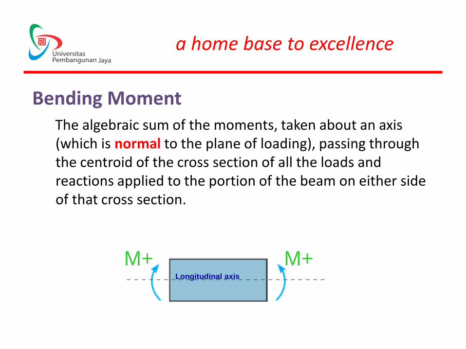
Bending MomentThe algebraic sum of the moments, taken about an axis (which is normal to the plane of loading), passing through the centroid of the cross section of all the loads and reactions applied to the portion of the beam on either side of that cross section.
Longitudinal axis
M+M+
a home base to excellence
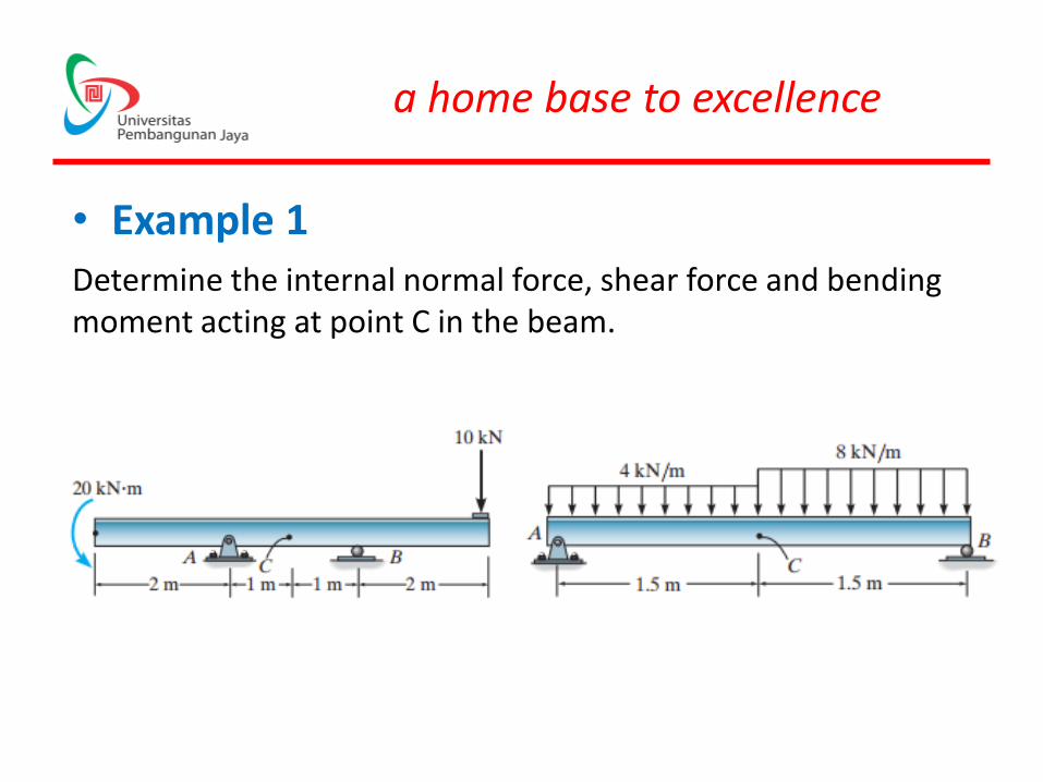
• Example 1Determine the internal normal force, shear force and bending moment acting at point C in the beam.
a home base to excellence
Shear and Moment Functions• The design of a beam requires a detailed knowledge of the
variations of the internal shear force V and moment M acting at each point along the axis of the beam.
• The variations of V and M as a function of the position x of an arbitrary point along the beam’s axis can be obtained by using the method of sections
• shear and moment functions must be determined for each region of the beam located between any two discontinuities of loading
a home base to excellence
Procedure for Analysis• Determine the support reactions on the beam
• Specify separate coordinates x and associated origins
• Section the beam perpendicular to its axis at each distance x, draw free-body diagram
• Vx and Mx obtained from equilibrium equation
• The results can be checked by noting that dM/dx = Vand dV/dx = q, where q is positive when it acts upward, away from the beam
a home base to excellence
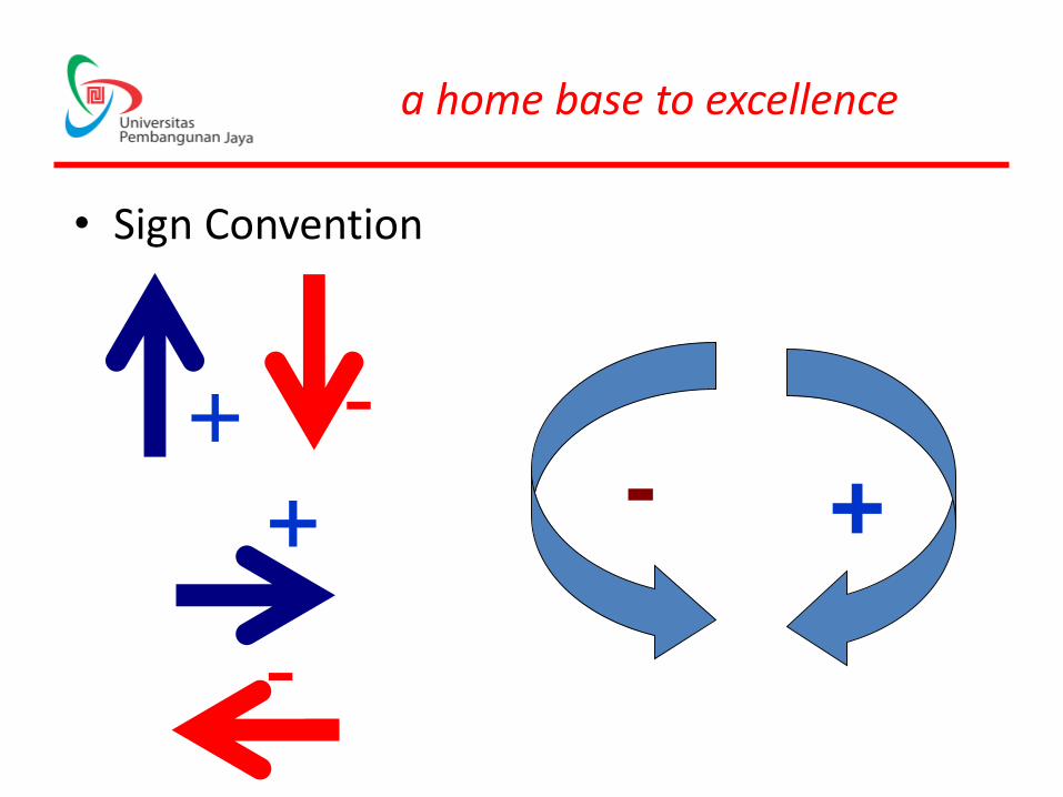
• Sign Convention
+ -
-
+-
a home base to excellence
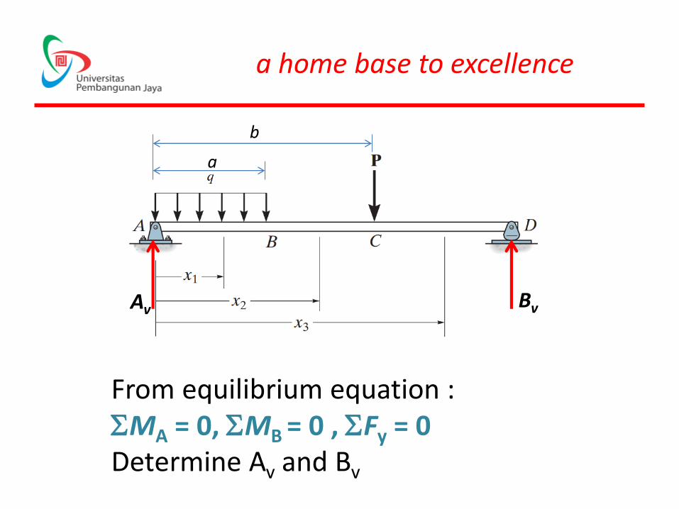
From equilibrium equation : SMA = 0, SMB = 0 , SFy = 0 Determine Av and Bv
Av Bv
a
b
a home base to excellence
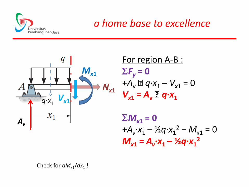
Vx1
Mx1
Nx1
Av
For region A-B :SFy = 0+Av q∙x1 – Vx1 = 0Vx1 = Av q∙x1
SMx1 = 0+Av∙x1 – ½q∙x1
2 − Mx1 = 0 Mx1 = Av∙x1 – ½q∙x1
2
q∙x1
Check for dMx1/dx1 !
a home base to excellence
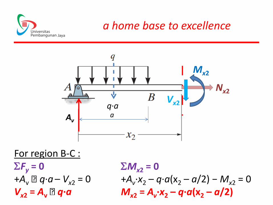
For region B-C :SFy = 0+Av q∙a – Vx2 = 0Vx2 = Av q∙a
Vx2
Mx2
Nx2
aq∙a
Av
SMx2 = 0+Av∙x2 – q∙a(x2 – a/2) − Mx2 = 0 Mx2 = Av∙x2 – q∙a(x2 – a/2)
a home base to excellence
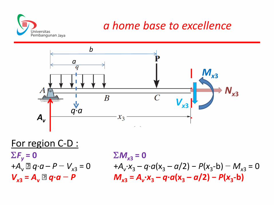
q∙aAv
a
b
Vx3
Mx3
Nx3
For region C-D :SFy = 0+Av q∙a – P − Vx3 = 0Vx3 = Av q∙a − P
SMx3 = 0+Av∙x3 – q∙a(x3 – a/2) − P(x3-b) − Mx3 = 0 Mx3 = Av∙x3 – q∙a(x3 – a/2) − P(x3-b)
a home base to excellence
• If the variations of V and M as functions of x are plotted, the graphs are termed the
shear force diagram (SFD)and bending moment diagram (BMD), respectively.
a home base to excellence
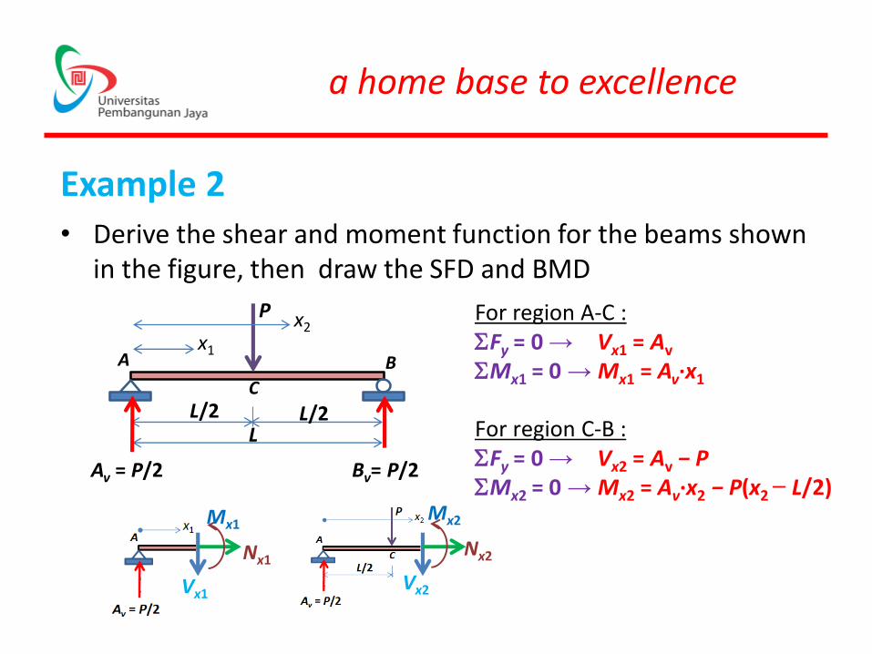
Example 2• Derive the shear and moment function for the beams shown
in the figure, then draw the SFD and BMD
P
L/2L
L/2
Av = P/2 Bv= P/2
A Bx1
x2
C
For region A-C :SFy = 0 → Vx1 = Av
SMx1 = 0 → Mx1 = Av∙x1
For region C-B :SFy = 0 → Vx2 = Av − PSMx2 = 0 → Mx2 = Av∙x2 − P(x2 − L/2)
Vx1
Mx1
Nx1
Vx2
Mx2
Nx2
a home base to excellence
+ PL/4
+ P/2
P
L/2L
L/2Av = P/2 Bv= P/2
A B
C
− P/2SFD
BMD
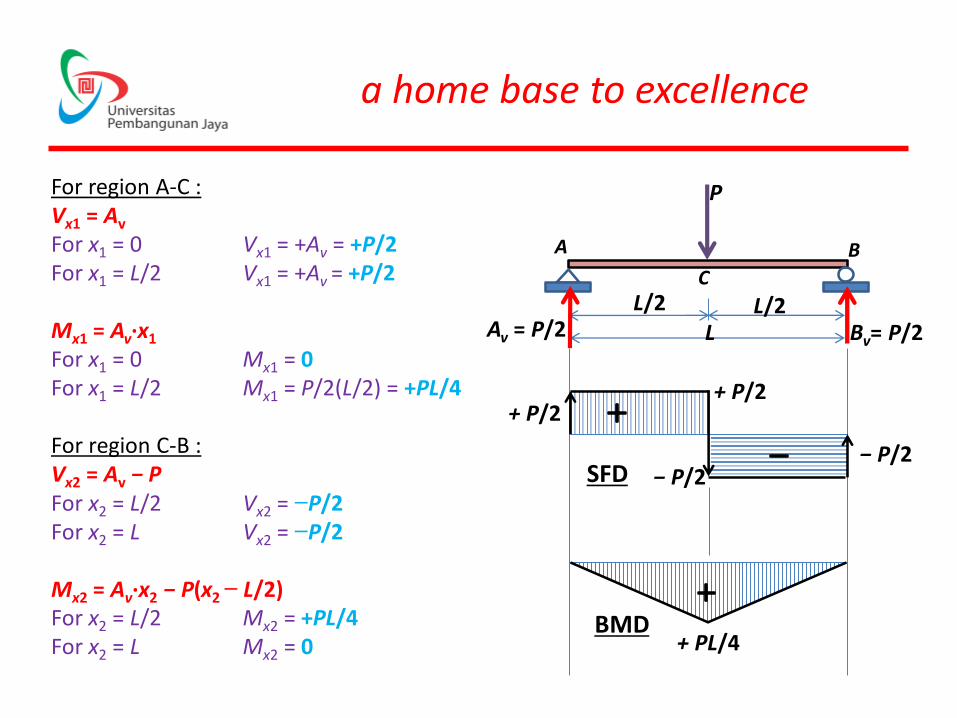
For region A-C :Vx1 = Av
For x1 = 0 Vx1 = +Av = +P/2For x1 = L/2 Vx1 = +Av = +P/2
Mx1 = Av∙x1
For x1 = 0 Mx1 = 0For x1 = L/2 Mx1 = P/2(L/2) = +PL/4
For region C-B :Vx2 = Av − PFor x2 = L/2 Vx2 = −P/2For x2 = L Vx2 = −P/2
Mx2 = Av∙x2 − P(x2 − L/2)For x2 = L/2 Mx2 = +PL/4 For x2 = L Mx2 = 0
− P/2
+ P/2
a home base to excellence
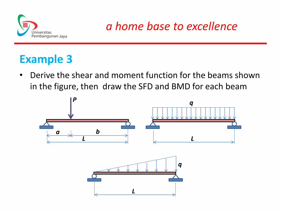
Example 3• Derive the shear and moment function for the beams shown
in the figure, then draw the SFD and BMD for each beam
P
a bL
q
L
q
L
a home base to excellence
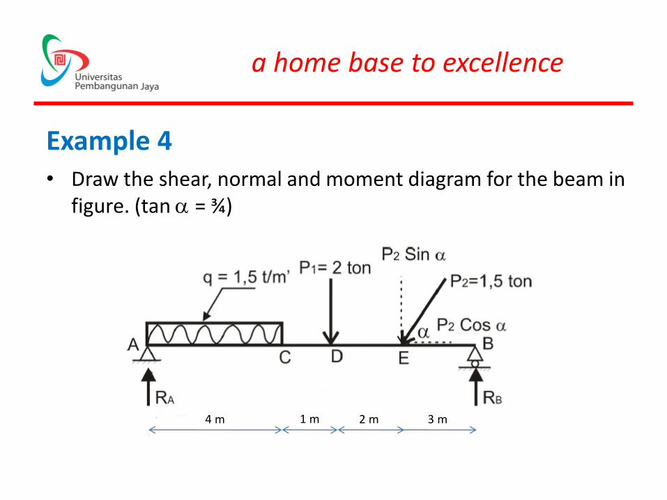
Example 4• Draw the shear, normal and moment diagram for the beam in
figure. (tan a = ¾)
4 m 1 m 2 m 3 m
a home base to excellence
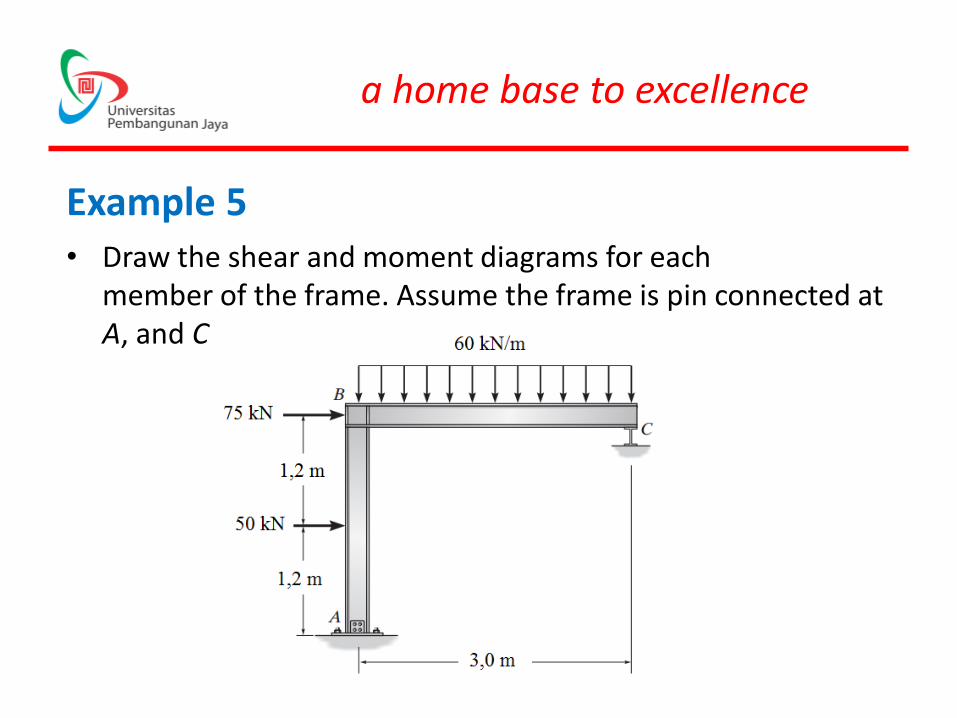
Example 5• Draw the shear and moment diagrams for each
member of the frame. Assume the frame is pin connected atA, and C is a roller.