electrodeposition of ni-co film: a review
TRANSCRIPT
Int. J. Electrochem. Sci., 16 (2021) 150962, doi: 10.20964/2021.01.16
International Journal of
ELECTROCHEMICAL SCIENCE
www.electrochemsci.org
Review
Electrodeposition of Ni-Co Film: A Review Inam M.A. Omar1,2, Khadijah M. Emran3,*, Madzlan Aziz4
1 Chemistry Department, College of Science, Taibah University, AlMaddinah Al Mounwara, SAUDI
ARABIA. 2 Department of Chemistry, Faculty of Science, Universiti Teknologi Malaysia, 81310 Johor Bahru,
Johor, MALAYSIA. 3 Chemistry Department, College of Science, Taibah University, AlMaddinah Al Mounwara, SAUDI
ARABIA 4 Department of Chemistry, Faculty of Science, Universiti Teknologi Malaysia, 81310 Johor Bahru,
Johor, MALAYSIA. *E-mail: [email protected]
Received: 25 September 2020 / Accepted: 3 November 2020 / Published: 30 November 2020
Nickel (Ni), cobalt (Co) and their alloy have been extensively employed in engineering due to their
magnetic, chemical, mechanical, physical and electrocatalytic characteristics, which grant resistance
against corrosion and heat. Electrodeposition is considered to be a significant and environmentally
friendly technique for producing Ni, Co and their alloy coatings due to its promising properties. The
current research provides a brief review of the latest studies of different types of Ni, Co, and Ni-Co alloy
electrodeposition from different aqueous baths. This article reviews the effects of various organic
additives in Ni, Co and their alloy electrodeposition processes. Due to the special functions of organic
additives, they are widely used during electrodeposition. The additives usually affect the growth and
crystal building of deposits through their adsorption on the cathode surface. The widened
electrochemical window, superior thermal stability, negligible or low vapor pressure and the
environmentally friendly characteristics of ionic liquids (ILs) permit them to be promising replacements
for traditional, toxic and volatile organic solvents.
Keywords: Electrodeposition, Ni-Co alloy, Ionic liquids, additives, Cathodic current efficiency,
Voltametric measurements.
1. INTRODUCTION
Several coating processes, including evaporation, hot metal processes, painting, thermal
spraying, metallizing and electrodeposition [1], are available commercially. These coating processes are
used to protect surface functionality and extend the component’s life. Electrodeposition or electroplating
is defined as an electrochemical process in which an applied potential or current is used for deposition
Int. J. Electrochem. Sci., Vol. 16, 2021
2
of a dense, uniform, and adherent single metal or alloy film by the reduction of metallic ions onto a
conductive substrate, including foils, wires and electroforms.
Electrodeposition processes have widespread uses due to their interesting properties compared
to other coating methods. Electrodeposition is considered to be an economical and environmentally
friendly process due to its lower operating temperature and pressure requirements, simpler
instrumentation, ease of fabrication and high-quality deposits. More interesting properties include the
possibility of predicting the chemical composition of deposits and easy control of deposit properties by
changing the electrodeposition parameters. The most common parameters are pH, bath composition,
temperature, current density, and additives. In addition, the electrodeposition process can achieve a high
level of chemical tunability, free porosity and uncontrolled oxide inclusion, can easily control the film
thickness, and can obtain good metal films on semiconductors and on a fabricated protein chip
[1][2][3][4][5][6][7][8][9][10]. The main efficient typical properties of deposited films are the
uniformity of the film thickness and dense, smooth, and bright surfaces with finer-grained structures.
There are other typical properties of deposited films, including great adhesion to the substrate, high
hardness, strength corrosion resistance, sufficient wear resistance, freedom from internal stress and good
ductility. Moreover, electroplating baths have many important features. They are stable and have a
cathodic current efficiency and throwing power, which are defined as the ability of the plating solution
to produce deposits of more or less uniform thickness on irregularly shaped cathodes [2].
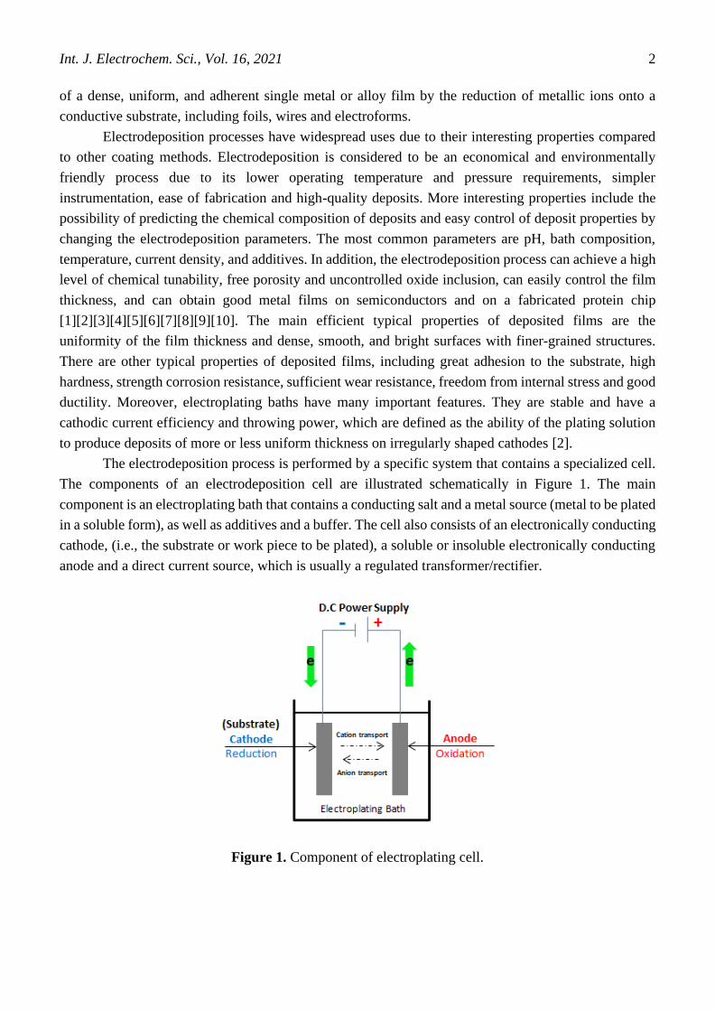
The electrodeposition process is performed by a specific system that contains a specialized cell.
The components of an electrodeposition cell are illustrated schematically in Figure 1. The main
component is an electroplating bath that contains a conducting salt and a metal source (metal to be plated
in a soluble form), as well as additives and a buffer. The cell also consists of an electronically conducting
cathode, (i.e., the substrate or work piece to be plated), a soluble or insoluble electronically conducting
anode and a direct current source, which is usually a regulated transformer/rectifier.
Figure 1. Component of electroplating cell.
Int. J. Electrochem. Sci., Vol. 16, 2021
3
The main important step in the electrodeposition process is cleaning or preparing the substrate
surface. To obtain a strong adherence metal deposit with the desired qualities, the substrate should be
free of any impurities or foreign materials, such as heavy scale oxide films, rust, workshop soils and oils,
grease, dirt, and any other material. The first cleaning step is descaling, which can be done by polishing,
tumbling and blasting with sand, grit or vapor, followed by a pickling process where the component is
immersed in acid to remove all “foreign” matter. The other cleaning methods are buffing, alkaline soak
cleaning, electrolytic cleaning and ultrasonic cleaning [1].
1.2 Electrodeposition of Alloys
An alloy is composed of two or more chemical elements, at least one of which is a metal. The
alloy coating has mixed metallic properties of the parent metal. The composition of the alloy is very
difficult to distinguish by the unaided eye. Through the electrodeposition process, it is possible to obtain
alloy coatings from two to four metals presented in the same bath [11]. Some examples of alloy coatings
are nickel–cobalt, zinc–cobalt, zinc–iron, zinc–nickel, brass (an alloy of copper and zinc), bronze
(copper–tin), tin–zinc, tin–nickel, tin–cobalt, and gold–copper–cadmium. Electrodeposition of alloys
has common and widespread applications in many industries, including electronics, communications,
automobiles, ships, air space, machinery, gold-silver wares and jewelry, defense, toys and production of
micro parts for Micro-Electro-Mechanical Systems (MEMS) and the synthesis of nanocrystalline
materials [1][4][3][6][8][9][10][12][13]. Among the wide range of electroplating materials available,
nickel (Ni), cobalt (Co) and Ni-Co alloys are important engineering materials used widely in numerous
industrial applications.
2. APPLICATIONS OF Ni, Co and Ni-Co ALLOYS IN INDUSTRY
2.1 Applications of Nickel
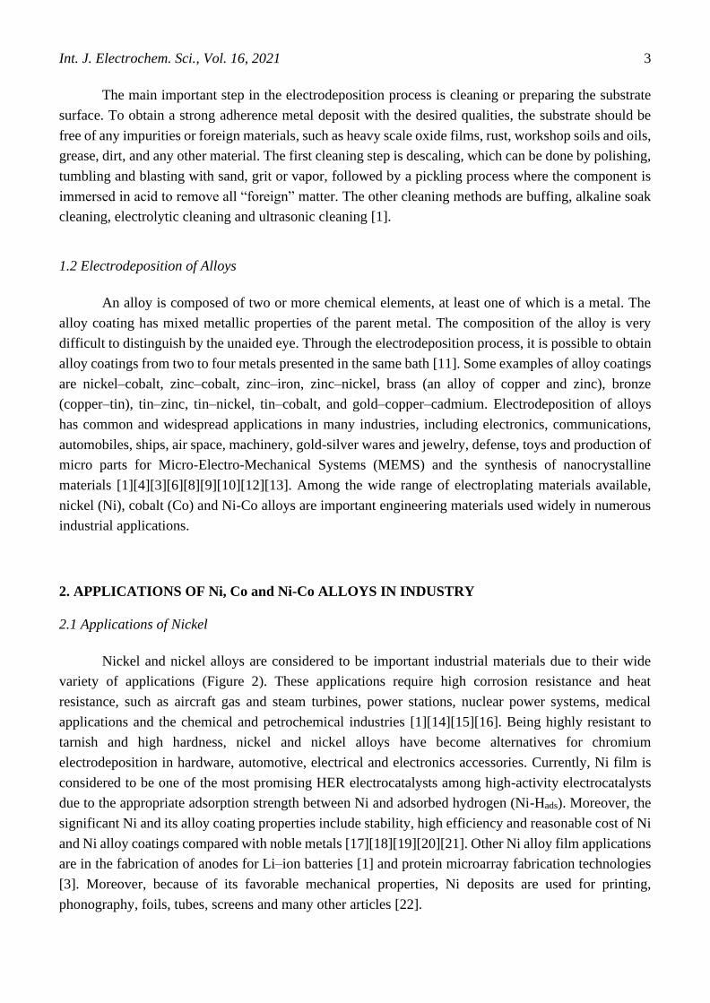
Nickel and nickel alloys are considered to be important industrial materials due to their wide
variety of applications (Figure 2). These applications require high corrosion resistance and heat
resistance, such as aircraft gas and steam turbines, power stations, nuclear power systems, medical
applications and the chemical and petrochemical industries [1][14][15][16]. Being highly resistant to
tarnish and high hardness, nickel and nickel alloys have become alternatives for chromium
electrodeposition in hardware, automotive, electrical and electronics accessories. Currently, Ni film is
considered to be one of the most promising HER electrocatalysts among high-activity electrocatalysts
due to the appropriate adsorption strength between Ni and adsorbed hydrogen (Ni-Hads). Moreover, the
significant Ni and its alloy coating properties include stability, high efficiency and reasonable cost of Ni
and Ni alloy coatings compared with noble metals [17][18][19][20][21]. Other Ni alloy film applications
are in the fabrication of anodes for Li–ion batteries [1] and protein microarray fabrication technologies
[3]. Moreover, because of its favorable mechanical properties, Ni deposits are used for printing,
phonography, foils, tubes, screens and many other articles [22].
Int. J. Electrochem. Sci., Vol. 16, 2021
4
2.2 Applications of Cobalt
Cobalt and cobalt alloys are considered to be important materials in engineering and are widely
used in many industrial applications. This is due to their unique properties, such as good strength and
thermal stability, heat conductivity, high hardness, corrosion resistance, good wear resistance, strong
adhesion, optical properties, and high catalytic characteristics [23][24][25]. Moreover, Co and its alloys
are used for producing nanostructure materials such as nanowires and nanotubes [4] and in various
storage and magnetic devices. Moreover, Co and its alloys are applied in microsystem technology for
the manufacture of sensors, actuators, micro relays, inductors and magnetic devices in the computer
industry [24][26][5], as shown in Figure 2. Additionally, it is used in modern accumulators and advanced
batteries, as well as in microelectronics for the semiconductor industry [4].
2.3 Applications of Ni-Co Alloy
Nickel-cobalt alloy deposits are very important due to their industrial applications (such as
electronics, computers, automotive and energy storage devices, particularly in the computer field),
technological (space, rocketry) applications [1][27][28], biotechnological applications [3] and powerful
fabrication applications [6]. These significant applications are due to nickel-cobalt alloys having suitable
magnetic, mechanical, chemical, physical and electrocatalytic properties (Figure 2). In addition,
electrodeposited Ni-Co alloys are widely used as active materials for hydrogen and oxygen evolution
reactions in water electrolysis, as anode materials for lithium batteries, and as catalysts for H2O2
decomposition [27][29]. Ni-Co films have been prepared via electrodeposition due to their low cost,
easy to maintain equipment, control of film thickness, preparation of high-quality alloys, and capability
of handling complex geometries. The method is environmentally friendly compared with other coating
technologies, such as physical and chemical vapor deposition [1].
Figure 2. Examples of different Ni-Co coatings applied on components in various industries.

Int. J. Electrochem. Sci., Vol. 16, 2021
5
3. A BRIEF REVIEW OF NICKEL ELECTRODEPOSITION
Extensive research has shown that Ni coatings, with careful selection of the bath composition
and application of appropriate techniques, provide distinguishable and adaptive solutions. Ibrahim et al.
[22] investigated Ni electrodeposition on steel substrates from acidic citrate baths. The CCE% was high
(91.7%), but the TP% of these baths was poor (7.4%) and strongly dependent on the operating
conditions. The Ni deposit surface morphology was achieved via SEM. The results revealed that a
compact, finer grained and free-porous Ni film was obtained from the optimum conditions. This superior
Ni film consisted of a mixture of phases.
The effect of adding glycine as a complexing agent to the electrodeposition of Ni on copper
substrates was studied [30]. The mechanism of deposition was investigated using electronic
spectroscopy, potentiodynamic cathodic polarization, CV, ALSV, and chronoamperometry techniques.
The Ni deposit morphology and phases were studied via XRD and SEM analyses. The results indicated
an accelerating effect of glycine on Ni2+ reduction. Finer grains with fine microcracks and non-
crystallinity of the Ni film were obtained in the presence of glycine. However, the TP%, Wagner number
and corrosion resistance of the Ni deposits decreased with glycine.
The influence of Cd2+ during Ni electrodeposition from the acidic sulfate baths was conducted
by Mohanty et al. [31]. The CCE% and the most preferred orientation (200) plane revealed from the
XRD were not significantly affected in the presence of Cd2+ up to 500 mg dm-3 in the Ni electrolyte. The
decrease in the exchange current density with an increasing Cd2+ concentration in the electrolyte
confirmed the cathode polarization and inhibition effect of Cd+2 ions during Ni electrodeposition on both
stainless steel substrates and Ni deposits. The magnitude of polarization of the cathode depends on the
bath composition, which follows the order NiSO4+H3BO3> NiSO4+H3BO3+Na2SO4> NiSO4+
Na2SO4>NiSO4.
The electrodeposition of Ni onto a platinum substrate from a Watts bath, including glycerol,
mannitol or sorbitol in the bath as additives, was studied by Oliveira et al. [16]. The studied additives
affect the kinetic parameters, as revealed via voltametric measurements, but they did not influence the
deposition thermodynamically. The current efficiencies recorded high values of 95% when polyalcohols
were present in the baths. At a higher hydrogen evolution state, the deposited film became clearer and
brighter. This finding suggested that the formation of the dark film was prevented by the studied
additives. SEM images revealed that a free-cracked Ni film was obtained from the solution, including
the studied additives. Glycerol exhibited the best leveling properties.
Ibrahim [7] studied the effect of adding KNO3 to the electrodeposition of Ni from Watt’s bath.
The study showed that under the optimal experimental conditions, a more leveled and stronger adherent
Ni film was produced. The compositions of the optimal bath are NiSO4.6H2O 0.63 M NiCl2.6H2O (0.09
M), H3BO3 (0.3 M) and KNO3 (0.2 M) at pH 4.6, i = 0.5 Adm-2, 25°C and 10 min. The modified Watts
bath has a high TP of 61%. The instantaneous nucleation of the Ni deposit was achieved from the current-
time transient analysis. The XRD pattern proved that a black and pure metallic Ni film was obtained
with a preferred Ni (111) orientation.
Acetone (AC) and thiourea (TU) affected the Ni electrodeposition from the ionic liquid, 1-butyl-
1-methylpyrrolidinium bis(trifluoromethylsulfonyl)amide (BMPTFSA) containing Ni(TFSA)2. The

Int. J. Electrochem. Sci., Vol. 16, 2021
6
UV–vis spectra showed that the coordination surrounding the Ni(II) ions was enhanced with AC.
However, the nucleation mechanism of Ni electrodeposition was not modified. The cathodic reduction
potential shifted toward a more positive potential when AC was included in the bath. The addition of
TU decreased the cathodic current peak with TU. The nucleation mechanism of the Ni film changed
from instantaneous to progressive in the presence of TU. This result is probably due to the TU adsorption
onto the electrode surface. According to the SEM, XPS and EDX characterizations, smoother Ni deposits
were obtained in the presence of the two studied additives than in the absence of the additives [32].
The corrosion resistance and microhardness of Ni electrodeposited from a Watts bath has been
improved via natural Kermes dye (NKD) as an effective additive using cathodic polarization behavior,
anodic linear stripping voltammetry, cyclic voltammetry, cathodic current efficiency, and current-time
transients. The microhardness was improved considerably, changing from 130.4 to 225 kg f mm-2 in the
presence of 8.0 x 10⁻⁵ M NKD. Moreover, the corrosion resistance of the Ni coating was enhanced
approximately five times in the presence of 1.0 x 10⁻⁵ M NKD. However, NKD did not change the
preferential orientation of the Ni crystal planes, as shown by the XRD analysis [33].
High-quality films of the Ni-Mn alloy were prepared in a choline chloride–urea ionic liquid
containing both 0.20 M NiCl2·6H2O and 1.50 M MnCl2·4H2O with the addition of glycine in order to
control the composition, microstructure and properties of the film. The effects of the glycine
concentration and current density on the electrodeposition mechanism of Ni–Mn alloy films were studied
by CVs. The reduction of Ni2+ ions was inhibited in the presence of glycine. However, the reduction of
Mn2+ is promoted by glycine. The Mn content in the Ni–Mn alloy increased when the concentration of
glycine and current density were increased. The lowest corrosion current of 3 × 10⁻⁷ A/cm2 was exhibited
in the Ni–Mn film with 3.1 % Mn compared with the other prepared films. The Ni–Mn film with 3.1 %
Mn exhibited a higher corrosion resistance than the pure Ni film in a 3.5 wt.% NaCl solution [34].
The Zn-Ni-Fe coating was co-deposited in the absence and presence of ascorbic acid (AA) and
the Fe2+ in solution on a low carbon steel substrate. The Fe2+ ions showed an insignificant influence
on the electrodeposition process, as illustrated in the CVs. However, a significant influence occurred
after spontaneous oxidation of Fe2+ to Fe3+ and the consequent formation of Fe(OH)3. The increase in
the Fe(OH)3 in solution led to a greater inhibition of the electrodeposit by adsorption at the cathode and
blocking the active sites that would be occupied by the metal ions. In general, the pure Zn in the Zn-Ni-
Fe co-deposit was decreased by the hydroxide and obtained a more compact and smooth coating of Zn-
Ni-Fe compared to Zn-Ni. However, the Zn content in the deposit increased in the presence of AA
because of the increasing overpotential deposition by complex adsorption on the surface of the cathode.
In conclusion, the Zn-Ni and Zn-Ni-Fe coatings deposited from AA included in solution were more
compact and had more uniform coatings than the other coatings obtained from the free AA solution. This
enhancement in the coating was due to an increase in the grain nucleation rate as a result of the increase
in the overpotential in the presence of additive [35].
Ni-P thin films were obtained in the presence of various additives (saccharine, glycine,
pyridinium propyl sulfonate, coumarin, sodium citrate, and cerium sulfate). The results showed that at
the appropriate concentration of each studied additive, except saccharine, a noticeable improvement in
the corrosion resistance, especially at high potentials (an approximately 25% increase in the
instantaneous corrosion efficiency and an approximately 300% corrosion efficiency at high potentials)
Int. J. Electrochem. Sci., Vol. 16, 2021
7
decreased the surface roughness (by approximately 10 to 55%) of the Ni-P thin films. Thinner, more
compact, and non-porous deposits were obtained from the system including additives. All the additives,
except saccharine, increased the P content in the Ni-P films, which thus maintained their amorphous
structure; saccharine highly suppressed the incorporation of P inside the Ni lattice, and a mixed
amorphous-crystalline structure was stabilized [36].
The synergistic effect of vanillin, sodium lauryl sulfate and gelatin as additives on Re-Ni
electrodeposition on copper substrates from aqueous solutions has been studied [37]. The effects of
additives and many other factors, such as bath composition, operating conditions, and current densities,
were investigated to improve the surface morphology of Re-rich Re-Ni alloy deposits. The presence of
additives exhibited a significant influence on the composition, surface morphology and cracking pattern
of the deposit. In addition, the surface morphology of the Re-Ni alloy changed from a uniform and
smooth surface without additives to a relatively coarse-grained surface with additives. The non-favored
cracked coating was enhanced in the presence of additives in the optimal bath containing 34 mM ReO4−,
124 mM Ni2+ and 343 mM [citrate]3−. At lower Ni ion concentrations (30–50 mM) in the presence of
additives, almost pure Re films were formed. Amorphous behavior was exhibited in the Re-rich alloy.
4. A BRIEF REVIEW OF COBALT ELECTRODEPOSITION
Various studies have illustrated the specific conditions and bath compositions in detail, including
additives in the electroplating of Co onto various substrates:
Abd El Rehim et al. [14] investigated Co electrodeposition onto steel substrates from acidic
sulfate solutions containing sodium gluconate. The cathodic current efficiency was high (~95%) and
depended on the operating conditions. The surface morphology indicated that the as-deposited Co under
the optimum conditions is composed of compact, microcracked, fine grains covering the entire substrate
surface. The microhardness of the as-deposited Co from the present bath is generally high. The TP of
the present bath was low (≈ 5.9 %).
Highly adherent, lustrous grey Co film was successfully electrodeposited from an acidic glycine
complexing bath on copper substrates. Voltametric measurements, including potentiodynamic cathodic
polarization, CV, ALSV and chronoamperometry, were studied. The cathodic potential shifted toward a
more negative direction when glycine was included in the bath. This finding indicated that glycine
complexes with Co ions act as inhibitors. Glycine-containing baths obtained deposits with a higher TP
and higher hardness than those deposited from glycine-free baths. The SEM images revealed that finer
grains with tiny microcrack Co deposits were produced from glycine-containing baths. Co coating are
non-crystalline, and the degree of non-crystallinity grows with an increasing glycine concentration [23].
In situ SERS measurements were studied for electrodeposition and stripping of Co films on Au
substrates from a coumarin-containing bath. Both cathodic deposition and anodic stripping were
investigated under suitable conditions. Many electrochemical polarization types have been considered,
such as cathodic potential staircases, potentiostatic electrodeposition and potentiostatic stripping of
potentiostatically pre-electrodeposited Co layers. Potential-dependent spectra measured via SERS
enhancement identified bands that allowed spectral assignment of coumarin and its reduction and
Int. J. Electrochem. Sci., Vol. 16, 2021
8
hydrolysis products. Moreover, the surface enhancement degree typically increased with the
electrodeposition time. The spectral patterns depend on the electrodeposition potential and the plating
time. The great spectral quality and remarkable sensitivity to the mode of grown Co film were
investigated from the stripping analysis [38].
The effects of coumarin and thiourea (TU) as addition agents on the electrodeposition of Co were
investigated in an amide-type ionic liquid, 1-butyl-1-methylpyrrolidinium
bis(trifluoromethylsulfonyl)amide (BMPTFSA). In both additive cases, the deposition potential of Co
shifted toward a less negative direction. The surface morphologies of the deposits were improved to be
more uniform, with finer grains and greater adhesion deposits. This finding was due to the specific
adsorption of both additives on the cathode surface. On the other hand, there was no change in the
coordination environment of Co2+ in the presence of coumarin. In contrast, in the case of TU, the
dissolved Co species were changed from [Co(TFSA)3]− to [Co(TU)4]
2+. The deposition potential of Co
from [Co(TU)4]2+ was more positive than that of [Co(TFSA)3]
−, and the surface morphology of the
deposit obtained from [Co(TU)4]2+ exhibited a higher enhancement [15].
Santos et al.,[5] investigated cobalt electrodeposition from sulfate solutions containing boric acid
by using EQCM coupled with potentiostatic techniques and the current–time transient. The Co
electrodeposition mechanism was affected significantly when the bath temperature increased. At 25°C,
only direct Co reduction is observed, while at 48°C, Co(OH)2 can be observed from the calculated
apparent M/z values. These results suggest that Co(OH)2 can be formed simultaneously with Co deposits
and that the buffer contribution of boric acid was ineffective at 48°C. For high temperatures the
adsorption mechanism was greater. This leads to an increase in the active surface area available for HER,
and Co(OH)2 can be formed.
Manhabosco et al. [26] studied the influence of saccharin as an additive in the electrodeposition
of Co thin films on silicon. Co reduction, kinetics, and hydrogen evolution were affected via the
saccharin molecules and a complexation process. The additive improves the appearance and brightness
of the metallic films. The brightness increases as the additive concentration rises.
Barrera et al.[25] highlighted the effect of KNO3 as an additive in Co electrodeposition from an
aqueous solution onto a stainless steel substrate. The composition of the bath was 1.17 M Co(II), 0.98
M H2SO4, 0.56 M KC1, and 0.2 M H3BO3. Analysis of the deposited Co surface via AFM and SEM
analysis revealed that the black Co film was more dispersed and had a higher roughness than the white
Co, while the white Co electrodeposition mechanism was shown to occur via multiple 3D, and nucleation
was limited by lattice incorporation of Co atoms into the growth centers.
Co-Pt thin films with many thicknesses were obtained by electrodeposition from an aqueous
hexachloroplatinate solution under controlled conditions (saccharin as an additive, pH 5.5, controlled
potential) on a sputtered Ru-substrate. The XRD measurements revealed that Co-Pt films crystallize in
the hcp phase. The compositional analysis of the films showed a “composition gradient”, which indicated
that the film thickness increased with and increasing Co concentration until reaching a steady value (for
thicknesses > 110 nm). MFM measurements were used to analyze the structure and width of the magnetic
domains. The results indicated that the thickness was dependent in the range of 20-250 nm [4].
Int. J. Electrochem. Sci., Vol. 16, 2021
9
5. A BRIEF REVIEW OF NICKLE-COBALT ALLOY ELECTRODEPOSITION
Electrodeposition of Ni-Co alloy and details of the co-deposition mechanism process, including
specific conditions, were investigated in the following studies:
A modified Watt’s bath was used in [24] to produce new Ni–Co alloys with various Co contents
via electrodeposition. The Ni–Co alloy electrodeposition mechanism and its surface morphology were
investigated via EIS, SEM and XRD. The results showed that with an increasing Co2+ ion concentration
in the electroplating bath, the charge transfer resistance increases, and the Warburg impedance of growth
in the Ni−Co layer decreases. The Co content in the Ni−Co alloy coatings increased anomalously, and
the strong Ni-Co (111) texture improved progressively. In addition, as the Co content increased up to
45% in the alloy coating, the grain size decreased and the hardness and strength of the alloy consequently
increased. However, at 55% Co, such parameters decreased.
The Ni-Co-W alloys were produced by electrodeposition on an Al net substrate in the absence
and presence of sodium citrate. The composition of the electrolytic baths was 20 g/L Ni, 8 g/L Co, W in
the range 2-8 g/L and boric acid at 20 g/L. The temperature of the bath and current density values were
changed in the ranges of 30-60°C and 260-350 A/m2, respectively. The best current efficiency and
specific energy consumption results were obtained in the presence of sodium citrate in the range of 30-
60°C, while the cell voltage was lower. The morphology and structure of deposits were investigated to
obtain the best deposit. The XRD affirmed that the main difference in the pattern of samples was from
sodium citrate. The electrolyte containing sodium citrate also exhibited an Ni fcc structure formation
[39].
Ni-Co-Fe-P quaternary alloys were prepared via electrodeposition. By changing the H3PO3
concentration in the plating electrolyte, the P content in the alloy was controlled. Consequently, the P
content of the Ni-Co-Fe-P coating increased with an increasing H3PO3 concentration in the electrolyte.
This increase in the H3PO3 concentration enhanced the coating morphology and led to the production of
a refined grain size, a pure amorphous material. The microhardness of the quaternary alloy coating grew
rapidly by approximately two times. The achievement of the anodic polarization results revealed that the
corrosion resistance of the alloy coatings decreased at lower H3PO3 concentrations but then increased at
higher H3PO3 additions. The best erosion–corrosion resistance was obtained with the Ni-Co-Fe-12.92P
coating. This finding is in good agreement with the hardness and the corrosion current density [11].
Ni-Co-Sn alloys were obtained by electrodeposition from a chlorine chloride (ChCl)-ethylene
glycol (EG) deep eutectic solvent (DES). Both the Ni-Sn and Co-Sn alloys were electrodeposited. The
Sn2+ ions supported DES electrochemical stability. CV measurements confirmed the alloy formation
because there were no cathodic or anodic peaks for individual elements. An XRD analysis revealed that
the binary and ternary alloy of Ni exhibited only the Ni lattice, and the other elements were included in
the Ni lattice. Furthermore, this result was confirmed via SEM images, and binary and ternary alloys of
Ni exhibit similar morphologies. The potentiodynamic polarization analysis revealed that the ternary Ni-
Co-Sn alloy coating has the highest stability in the anodic region in an alkaline solution [40].
The influence of nano-Al2O3 particles has been studied in Ni-Co deposit films. The presence of
such particles improved the corrosion protection, the surface morphology, and the structure of Ni-Co
alloy layers compared to free-Al2O3-Ni–Co deposited alloy, as exhibited in the potentiodynamic
Int. J. Electrochem. Sci., Vol. 16, 2021
10
polarization results and SEM. Moreover, the resistance against corrosion of the alloy was further
improved as the pH of the electrodeposition bath and the Co content in the alloy increased. More
homogeneous, fine-grained deposits were obtained by increasing the Ni2+/Co2+ ratio in the electrolyte
[28].
Yang et al. [41] produced bright Ni-Co alloy foils on a titanium substrate via electrodeposition
from an acid chloride-sulfate bath by optimization of the electrodeposition parameters. The bright
deposit current density, temperature, and pH value range are 3-4 A dm-2, 40-50°C and 2-3, respectively.
The optimized concentration of cobalt sulfate is 20 g/L and that of saccharin is 2-3 g/L. The
crystallographic structure of Ni-Co deposited foil is the fcc Ni solid solution. The deposit is uniform fine
grained and shows a good toughness and low residual stress.
6. CIRCUIT FOR ELECTRODEPOSITION.
The plating cell, as shown in Figure 3, is made from transparent Perspex in the form of a
rectangular trough. The cell has inside dimensions of an 11 cm length, a 3 cm width and a 2.5 cm height,
and will be used for measurements of cathodic current efficiency and all other voltametric measurements.
For the throwing power and throwing index measurements, the Harring Blum cell shown in Figure 6,
which has inside dimensions of a 17.5 cm length, a 3 cm width and a 2.5 cm height, is used. Both cells
are designed with vertical grooves on each of the walls side that are 2.5 cm apart from each other, and
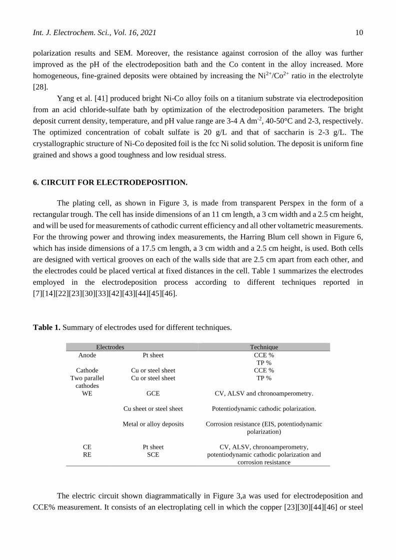
the electrodes could be placed vertical at fixed distances in the cell. Table 1 summarizes the electrodes
employed in the electrodeposition process according to different techniques reported in
[7][14][22][23][30][33][42][43][44][45][46].
Table 1. Summary of electrodes used for different techniques.
Electrodes Technique
Anode
Pt sheet CCE %
TP %
Cathode Cu or steel sheet CCE %
Two parallel
cathodes
Cu or steel sheet TP %
WE GCE CV, ALSV and chronoamperometry.
Cu sheet or steel sheet Potentiodynamic cathodic polarization.
Metal or alloy deposits Corrosion resistance (EIS, potentiodynamic
polarization)
CE Pt sheet CV, ALSV, chronoamperometry,
potentiodynamic cathodic polarization and
corrosion resistance
RE
SCE
The electric circuit shown diagrammatically in Figure 3,a was used for electrodeposition and
CCE% measurement. It consists of an electroplating cell in which the copper [23][30][44][46] or steel

Int. J. Electrochem. Sci., Vol. 16, 2021
11
[7][14][22][33][42][43][45] cathode is inserted with a platinum anode and fixed in their appropriate
positions. A D.C. regulated power supply is connected to supply the required current density. Figure 3,b
shows a diagram of the electric circuit used for potentiodynamic cathodic polarization
[22][42][43][44][45] and corrosion resistance [23][30][33][46] measurements. The electroplating cell
consists of an appropriate WE inserted with the platinum sheet as a CE (Table 1). In the corrosion
resistance measurements, the WE was metal or alloy deposits. The CV, ALSV and chronoamperometry
(potentiostatic current-time transients) [23][30][43][44][45][46] were measured by an electrical circuit,
as shown in Figure 3,c. This consisted of an electroplating cell, in which a platinum sheet is used as a
CE, the GCE is used as the working electrode (WE) and the SCE is used as the reference electrode (RE),
Table 1. The SCE as an RE is placed near the working electrode, and the three electrodes are connected
to a potentiostat/galvanostat, which is connected to a personal computer. Software packages were used
to measure and analyze data. The throwing power and throwing index of the plating solutions are
measured in a Harring Blum cell [14][22][23][30][33][42][43][44][45][46], as shown in Figure 3,d,
which has inside dimensions of a 17.5 cm length, a 3 cm width and a 2.5 cm height is used. The cell is
provided with one platinum anode between two parallel copper or steel sheets as cathodes (Table 1) at
different distances (1:1-1:5).
Figure 3. The electroplating cell and the electrical circuit used for measuring (a) the electrodeposition
and CCE%, (b) potentiodynamic CP and corrosion resistance, (c) CV and ALSV, and (d) the
throwing power and throwing index.
For individual deposition of the single metals, the CCE% is simply calculated according to
Faraday's law from equation (1):
CCE % = W𝑝
Wt × 100 (1)
Int. J. Electrochem. Sci., Vol. 16, 2021
12
Where Wp is the practical weight of the deposit, and the theoretical weight of the deposit Wt is
calculated using Faraday's law [47][2]. The CCE% of the alloys is determined by the method reported
in [1][47]. The partial current efficiencies % of the parent metals, CCENi % and CCECo, in the alloy were
calculated using the following relations:
CCENi % = 𝑊𝑁𝑖
W𝑡× 100 (2)
CCE Co % = 𝑊𝐶𝑜
W𝑡× 100 (3)
Where wNi and wCo are the practical weights of the Ni and Co deposits, respectively. The Wp of
the parent metals in an alloy are obtained from the composition of the alloy. The alloy composition is
then determined by an EDS analysis. Then, the total alloy efficiency, CCE alloy, is equal to the sum of
CCENi and CCECo:
CCE alloy= CCE Ni + CCE Co (4)
Through power (TP) and throwing index (TI) calculations, the two cathodes (Cu) are weighed
before and after electrodeposition for a certain time at a settled current density. In each case, the throwing
power is calculated at the linear ratio "L = 3" using Field's formula [1][2].
TP % =L−M
L+M−2×100 (5)
Where L is the linear distance ratio and M is the metal distribution ratio. These are defined as
reported in [1][2]
Linear ratio (L) = Distance of a far cathode
Distance of a near cathode (6)
Metal ratio (M) = Weight of deposit on near cathode
Weight of deposit on far cathode (7)
With regard to the above formula, the TP of different solutions can be obtained. From the
experimental weights of the metal deposited on the two cathodes, the near and far cathodes, the metal
distribution ratio (M) is calculated and then plotted versus the linear ratio (L) on arithmetic coordinates.
The reciprocal of the slope of this plot is called the "throwing index".
7. IONIC LIQUIDS (ILs)
The molten salts ,which are melted at lower than 100 °C and contained of cations as well as
anions, are classified in the chemistry as ionic liquids. The unstable charge positions of the ionic liquid
ions cause them to melt at a low temperature [48]. Commonly used ionic liquids cations are those
consisting from alkylpyridinium, alkylimidazolium, alkylphosphonium, alkylammonium and
alkylguanidinium. However, the most common ionic liquids anions are chloride, tetrafluoroborate and
methylsulfate. Generally speaking, the various ionic liquids anions control the miscibility points of these
compounds in water. Moreover, the obtaining of ILs is commonly achieved by metathesis, beginning
from pioneer chloride salts. The ILs cations are adsorbed at the surface of cathode at the appropriated
deposition potential. Consequently, the fabric of the double layer is depended on cation, which impacts
some ILs such as conductivity and viscosity of these solutions [49]. The ionic liquids are considered as
versatile properties compounds which are consisted from several kinds including binary and ternary
mixtures. The most common ionic liquids are classified into three main systems as the following:

Int. J. Electrochem. Sci., Vol. 16, 2021
13
a) Systems established from AlCl3 and organic salts such as 1-butylpyrridinium chloride and 1-
alkyl-3-methylimidazolium chloride.
b) Systems established from organic cations as in the first group as well as anions BF4, PF6 and
SbF6.
c) Systems established from the aforementioned organic cations with anions of the type CF3SO3
and similar [9].
7.1 Properties and Advantages of Ionic Liquids:
The unique structural characteristics of ionic liquids give them several distinct characters which
qualified them for various applications. The most important ionic liquid property is its large
electrochemical window ( > 5 V). This property gives access to electrodeposits of some elements, such
as Mg, Al, Ta and Ti, that are hard to electrodeposit from aqueous or organic media at modest
temperatures. The electrodeposition process is affected via both anions and cations of ILs. Generally,
the physical characters of the IL salt, such as its crystal structure and the appearance of its surface
morphology, are controlled by cations. However, the main role of the anion is exhibited in the chemical
reactivity of ILs and its stability. Furthermore, the anions performed an effective role in the coordination
geometry as well as other factors such as the nucleation mechanism, the potential and the current of
metal reduction. Moreover, a convenient choice of both cation and anion radicals influences the ILs
solubility, polarity, viscosity, and density. Moreover, a higher ILs conductivity, in the range from 10-3
to 10-2 Ω-1 cm-1, in the comparison with that of organic solvents or electrolytes qualifies ILs for
performing the electrodeposition process at low temperatures. The ILs effort an ability for performing
some experiments which required very high temperatures, up to 400 °C due to its extremely low vapor
pressures, in the range from 10-11 to 10-10 at room temperature.
The high thermal stability of ionic liquids has qualified them for use at wide range of temperature.
In the environmental perspective view, ionic liquids are considered as more environmentally friendly,
greener and cleaner than many toxic solutions. Finally, ionic liquids became more effective solvents in
the both organics and inorganics medias. The electrodeposition potentials of the single metal ions are
much closer together in ionic liquids, enabling easier electroplated alloys [47][50]. In conclusion, ILs
are considered as definitely advanced promising technological solvents which are designed for a
convenient and particular applications.
7.2 Applications of Ionic Liquids in Electrodeposition:
The unique, convenient and promising characters of ionic liquids, several industries applied ILs
at many important aspects. The most interesting application could be mentioned in brief including
synthesis, electrodeposition, extraction processes, electrochemistry, photochemistry, liquid crystals,
CO2 capture, green corrosion inhibitors for metal anti-corrosion, desulfurization of fuel, enzymatic
synthesis, lubrication, rocket propulsion and thermal storage devices. In the electrochemistry:

Int. J. Electrochem. Sci., Vol. 16, 2021
14
- The very modest vapor pressure of ionic liquids led them for green using in the open galvanic
solutions at variable temperatures via preventing the emission of the deleterious vapors. As result, the
amount of volatile organic compounds released into the atmosphere reduced significantly.
- A significant energy savings are afforded through the ionic liquids great conductivity compared
with aqueous solutions.
- The ionic liquids provides green, recyclable and environmentally friendly options for synthetic
organic chemistry, separation sciences, chemical and engineering sciences.
- The ionic liquids, due to their high ion concentration, excellent stability and great ionic
conductivity, become a beneficial materials for electrical energy storage devices, such as electrolytic
capacitors, batteries and fuel cells, as well as supporting media for catalysts [50].
7.3 The Importance of Ionic Liquids as Additives and Corrosion Inhibitors.
In the electrodeposition of metals and alloys, additives are commonly used due to their
convenient roles. The additives have influenced in both the coating films characterization and the
microstructure of deposits crystals. This phenomenon occurred through additives adsorbtion on the
electrode surface. Some traditional colloidal and organic compounds additives have been widely used in
industry and have achieved strong additives. However, many organic additives are easy and fast to
degrade or they are not green materials. Moreover, many organic substances have some disadvantages,
such as a low thermal stability, a poor chemical activity and high toxicity. Consequently, there are
continuing efforts for obtaining more efficient additives that combine a good stability, high efficiency
and environmental friendliness.
There is a similarity between additives of electrodeposition and corrosion inhibitors in terms of
their mechanism effect, which is both of their adsorption abilities on the substrate surface. However,
many commercially common inhibitors are toxic substances that should be replaced by new, more eco-
friendly ones. Currently, many researchers have focused on using inexpensive, efficient molecules and
environmentally friendly materials as corrosion inhibitors [51]. The main difference between them is
that the additives are studied under an electric field. The adsorption behavior are controlled by the
electric field distribution. In contrast, there is no galvanization in the corrosion inhibition process. The
adsorption of corrosion inhibitors depends on certain physicochemical properties of the inhibitor group,
such as electron density at the donor atom, the π-orbital character and the electronic structure of the
molecule [51].
ILs are compounds that are contained from two main radicals, organic cations and organic or
inorganic anions in the liquid state at low temperatures. The high cationic configuration of ILs readily
facilities them for adsorption on the cathode surface under an electric field. Moreover, some functional
groups, such as the –C=N– group, –C=O, I-, F-, and electronegative heteroatom in the molecule of ILs
enable them for a spontaneous adsorption on the metal substrate surface. This finding is due to the
specific interaction between the active centers of the functional groups in the ILs molecules and the
metal surface [51]. Interestingly, ILs have become a promising alternative for non-environmentally
volatile organic compounds.
Int. J. Electrochem. Sci., Vol. 16, 2021
15
7.4 Ionic Liquid as an Electrolyte Or Additive In Electrodeposition.
Studies have proven the striking function of ionic liquids as electrolytes or additives in the
electroplating of alloys:
Zhu et al. [27] mentioned Ni electrodeposition from an ionic liquid, 1-butyl-1-
methylpyrrolidinium bis(trifluoromethylsulfonyl)amide (BMPTFSA) containing Ni(TFSA)2, by using
acetonitrile (ACN) as an addition agent. ACN exhibited a change in the BMPTFSA ionic liquid color as
a result of changing the Ni(II) coordination number from [Ni(TFSA)3]−to [Ni(ACN)6]
2+, as confirmed
by UV–vis and FT-IR spectroscopy. The Ni coating nucleation mechanism remained constant even
though the Ni ion coordination environment was changed. However, a higher range of nuclei is generated
on the cathode surface, as confirmed via chronoamperometric measurements. The SEM images showed
that smoother Ni deposits were obtained from Ni(TFSA)2/BMPTFSA with ACN.
The same authors of a previous study discussed the effective role of coumarin and saccharin [52]
as additives in Ni electrodeposition under the same ionic liquid solution. As confirmed via UV-vis
analysis, the Ni2+ coordination number stayed the same as coumarin or saccharin. However, the
overpotentials for the Ni2+ reduction increased, but the current density decreased. The diffusion
coefficients of Ni2+ with both studied additives were estimated to be near those in the free-additive
electrolyte, as confirmed by a chronoamperometry study. The nucleation mechanism model of the Ni
coating fluctuated from instantaneous to progressive with both coumarin and saccharin. The influence
of the two studied additives exhibited a good enhancement on the Ni deposit surface morphology.
The electrodeposition mechanism of Ni–Cu alloy coatings was obtained from a choline chloride–
urea (1:2 molar ratio) eutectic-based ionic liquid (1:2ChCl–urea IL) on a Cu substrate. Cyclic
voltammograms confirmed the high possibility of obtaining Ni–Cu alloy films from a 1:2 ChCl–urea
ionic liquid bath with no need for complexing agents due to their close onset reduction potentials. The
nucleation mechanism of Ni–Cu deposits followed the instantaneous 3D model, as revealed via
chronoamperometric analysis. A denser surface of the Ni–Cu alloy coating was produced at a lower
deposition current density and a lower Cu content in the alloy, as revealed by the SEM/EDX analysis.
Under similar conditions, the XRD pattern showed an enhancement in the preferential orientation of the
Ni(1 1 1) plane with a high current density. The greatest corrosion resistance of the Ni–Cu alloy coating
was obtained with ∼17.6 % Cu content in the alloy, as confirmed via potentiodynamic polarization [53].
The presence of many ionic liquids in the electrolyte containing five transition metals was
obtained by dissolving bistriflimide salts of Ag, Cu, Co, Ni and zinc in 1-butyl-3-methylimidazolium
bistriflimide ([bmim][Tf2N]) in a 1:2 molar ratio. With the exception of the Ni system, for all ionic
liquids it became possible to obtain the metal deposits in a normal air atmosphere. Therefore, a
homogeneous and free-cracked silver deposit was obtained potentiostatically from the studied ionic
liquid.
Silver deposits are considered electroactive and follow a progressive nucleation mechanism in
non-wet media. In contrast, the other systems, including the copper-cobalt and zinc-bearing systems,
were strongly moisture sensitive. The copper electrodeposits could only be obtained from wet media.
The nucleation and growth mechanism obey the progressive model. Consequently, globular crystal
blocks are formed. Silvery zinc coatings with strong adherence could be achieved in both “wet” and
Int. J. Electrochem. Sci., Vol. 16, 2021
16
“dry” media. In conclusion, in all previous cases, except for Ni, both metal or mixed metal oxides can
be electrodeposited via direct electrodeposition at room temperature in open air conditions [54].
Ni-Mo and Co-Mo alloy coatings were electrodeposited from Ch-Cl-based ionic liquids onto Cu
substrates. The electrolytes contained Ni2+, Co2+ and Mo6+ ions in Ch-Cl-urea-citric acid. Ni-Mo alloys
with 2–35 Mo% and Co-Mo alloy with 6–63 Mo% exhibited excellent adherence and uniformity and a
nanocrystalline structure, where the average crystallite sizes=3-7 nm. Moreover, Ni-Mo alloy, with 8–9
Mo%, and Co-Mo alloy, with 10–12 Mo%, appeared to have greater corrosion protection than those
electrodeposited in classical aqueous electrolytes, suggesting the gradual formation of a protective
passive film on the surface [55].
Thick Ni-Fe-Mo and Ni-Fe-W alloy films were electrodeposited using a constant current
technique on a Cu microwire (50 μm) from a citrate bath, including a 1-dodecyl-3-methylimidazolium
chloride IL. The magnetic properties, composition and structure of the coatings were investigated in the
presence of IL. Uniform, free damage and the amorphous/nanocrystalline coating were obtained under
optimized experimental conditions as shown from SEM and XRD analysis. EDX measurements revealed
that the coatings with Ni32Fe48Mo20 and Ni52Fe33W15 exhibited the best properties. The relatively high
saturation magnetization (65.3 and 37.08 emu/g), low coercivity Hc (4.0 and 12.0) and satisfactory GMI
ratios (102.2% and 20.1%) qualified this coating as a promising material for magnetic sensor
applications. The content of both W and Mo could be easily tuned in a solution containing IL. The
studied IL played a very effective role in producing compact and uniform alloy coatings. These films of
desired composition are considered to be prospective films for use as catalysts and electrode materials
in different industries, such as fuel cells, hydrogen revolution reactions or sensing elements in magnetic
sensors [56].
Ni–Mo alloy coating was deposited from an ammonia citrate bath including 1-ethyl-3-methyl-
imidazolium chloride ionic liquid as an additive on mild steel by using the pulse plating technique. The
results showed that the Mo content in the Ni–Mo alloy increased to more than 50 % under the optimal
conditions of 10 ppm ionic liquid, pH 8.5, and 200 rpm rotation. Moreover, an adherent, compact and
bright Ni–Mo alloy coating was obtained under the optimal conditions, as revealed from the SEM
images. The XRD patterns showed amorphous/nanocrystalline Ni–Mo coatings deposited under pest
conditions [57].
In his major study, Ibrahim et al. identified the role of a 1-butyl-3-methylpyridinium bromide
[BMPy]Br ionic liquid as an additive on zinc coating characteristics from acidic sulfate electrolytes.
Cathodic polarization and cyclic voltammetry measurements were employed to determine the deposition
mechanism. A high nucleation overpotential was shown in CVs in the presence of [BMPy]Br,
confirming the inhibition of Zn ion deposition. The kinetic parameters were calculated from the Tafel
plots and exhibited a strong inhibiting effect of [BMPy]Br on Zn ion reduction. A homogenous and finer-
grained Zn coating was obtained at low [BMPy]Br concentrations. The XRD pattern showed that the
studied additive had no effect on the Zn coating crystal structure, but strongly affected the
crystallographic orientation of the crystal planes. The TP of the deposition electrolyte with [BMPy]Br
was more than doubly increased [42].
Int. J. Electrochem. Sci., Vol. 16, 2021
17
8. CONCLUSION
Electrodeposition is considered to be an economical and environmentally friendly process due to
its interesting properties. Nickel and its alloys are used for an enormous variety of industrial applications,
especially those that require high corrosion, heat resistance and hardness. Currently, metallic Ni is
considered to be one of the most promising HER electrocatalysts. Cobalt and its alloys are considered
interesting materials in the engineering field, which qualifies them for common utilization in many
industrial applications due to their unique properties, including great corrosion protection, high strength
and hardness, good adhesion, thermal stability, heat conduction, desirable optical properties, and
excellent catalytic characteristics. The novel, green and efficient addition agents in Ni and Co and their
alloy electrodeposition process have become attractive goals for many researchers. Many attempts have
been made to find new additives to improve deposit characterizations and operating conditions. These
attempts are mainly represented in the CE as well as cathodic polarization. Many researchers have
successfully achieved a convenient correlation among the deposit morphology, crystallographic
orientations of grains, CCE% values of the electrolytes and the reflected kinetic parameters. The
following summaries conclude the main important key points:
- In Ni electroreduction, acidic citrate and polyalcohol additives in the electroplating baths
exhibited high CCE% (91.7% and 95%, respectively), and the Ni deposit was composed of free-porous,
finer grains and compact covering. Adding KNO3 to Watt’s bath produces smooth and highly adherent
black Ni with a high TP of 61%. Glycine played an accelerator role in Ni2+ electroreduction. The SEM
and XRD analysis revealed finer grains with fine microcracks and an increasing non-crystallinity of the
Ni film. Glycerol, mannitol or sorbitol showed excellent leveling properties because the smoothest film
was obtained. The corrosion resistance and microhardness of the Ni deposited from a Watts bath have
been improved by natural Kermes dye (NKD) as an efficient additive.
- In the Co electrodeposition, solutions containing the CCE% (~95%) and the microhardness of
the Co deposit were high in the presence of sodium gluconate. Glycine acts as an inhibitor and obtained
a higher TP and hardness than glycine-free baths, and the non-crystalline degree of the Co coating grew
with an increasing glycine concentration. The surface morphology of the Co coating with sodium
gluconate and glycine had compact, fine grains with the appearance of fine microcracks. In both the
coumarin and thiourea additives, the deposition potential of Co shifted toward a more positive direction.
The surface morphology of the deposits was enhanced to a more homogenous, lower granular and
stronger adhesion. This finding suggests the specific adsorption of both additives on the cathode surface.
Boric acid and the EQCM technique increase the adsorption rate and the active centers available for
HER in Co electrodeposition. As a result, Co(OH)2 can be obtained at high temperatures. Adding
saccharin modifies the metallic appearance of the Co film, which shows a higher brightness as the
additive concentration increases.
- In the co-deposition of Ni–Co alloys, as the Co content increased above 45% in the alloy
deposits, the grain size became finer, but the hardness of the alloy consequently increased. To obtain the
Ni-Co-W alloys, the best CCE% and specific energy consumption results were obtained with sodium
citrate. The refined grain size, pure amorphous material, microhardness and corrosion resistance of the
Ni-Co-Fe-P quaternary alloy deposit increased significantly at high H3PO3 concentrations in the
Int. J. Electrochem. Sci., Vol. 16, 2021
18
electrolyte. The Ni-Co-Sn alloy electrodeposited from the ChCl-ethylene glycol-DES is more stable in
the anodic region in the alkaline solution, and the stability of the DES increased in the presence of Sn+2
ions. The presence of nano-Al2O3 particles improved the corrosion properties, morphology, and
microstructure of the Ni–Co alloy deposit film. The Ni-Co alloy foil deposit was bright, uniform, fine
grained, and had a good toughness and low residual stress with 2-3 g/L of saccharin.
The promising properties of ionic liquids (ILs) qualify them as green alternatives for volatile and
toxic organic solutions. ILs contain organic cations and organic or inorganic anions that are in the liquid
state, even though the temperature is low. The great configuration of their cationic and some functional
groups readily led them to spontaneous adsorption on the metal surface due to the specific interaction
between these functional groups and the metal surface. Many studies have proven the effective function
of ionic liquids as electrolytes or additives in the electroplating of alloys as follows: more leveled
deposits were obtained in Ni(TFSA)2/BMPTFSA ionic liquids with CAN. Ni–Cu alloy films from a
ChCl–urea -DES ionic liquid containing ∼17.6% Cu obtained the strongest corrosion resistance as a
result of the dense and free-cracked structure. Good adherence, uniformity and an improved corrosion
performance of Ni-Mo and Co-Mo alloy films from the ChCl ionic liquids were investigated, and both
alloy films exhibited a nanocrystalline structure. A strong adherent, as well as a more compact and
brighter Ni–Mo alloy was obtained from a bath including 1-ethyl-3-methyl-imidazolium chloride ionic
liquid as an additive in an ammonia citrate media using the pulse plating technique. Bright and adherent
thick films of Ni-Fe-Mo and Ni-Fe-W alloys were electrodeposited by a constant current technique from
a citrate-based bath containing a 1-dodecyl-3-methylimidazolium chloride ionic liquid.
References
1. R.M. Al Raddadi, Cathodic codeposition of nickel-cobalt alloy coatings from acidic glycine
complex baths, (2014) Taibah university, KSA.
2. E.M.A. Omar, Effect of Organic Additives on Zinc Electrodeposition from Acidic Sulfate Bath,
(2012) Taibah University, KSA.
3. Y.J. Chang, S.Z. Chen and C.Y. Ho, Colloids Surf., B., 128 (2015) 55.
4. O. Dragos-Pinzaru, A. Ghemes, H. Chiriac, N. Lupu, M. Grigoras, S. Riemer and I. Tabakovic, J.
Alloys Compd., 718 (2017) 319.
5. J.S. Santos, R. Matos, F. Trivinho-Strixino and E.C. Pereira, Electrochim. Acta, 53 (2007) 644.
6. C.D. Grill, J.P. Kollender and A.W. Hassel, Phys. Status Solidi,. 212 (2015) 1216.
7. M.A.M. Ibrahim, J. Appl. Electrochem., 36 (2006) 295.
8. A. Panda, Electrodeposition of nickel-copper alloys and nickel-copper-alumina nanocomposites
into deep recesses for MEMS, (2003) Anna University, Chennai, India.
9. S. Budi, B. Kurniawan, D.M. Mott, S. Maenosono, A.A. Umar and A. Manaf, Thin Solid Films.,
642 (2017) 51.
10. W. Schwarzacher, Electrochem. Soc. Interface. 15 (2006) 32.
11. X. Ji, C. Yan, H. Duan and C. Luo, Surf. Coatings Technol., 302 (2016) 208.
12. H.H. Lou, Encycl. Chem. Process., (2006) 1. https://doi.org/10.1081/E-ECHP-120007747.
13. R.S. Bakdash, Codeposition of Copper-Zinc Alloy from Acidic Bath Containing Monosodium
Glutamate, (2014) Taibah University, KSA.
14. S.S.A. El Rehim, M.A.M. Ibrahim and M.M. Dankeria, J. Appl. Electrochem., 32 (2002) 1019.
15. R. Fukui, Y. Katayama and T. Miura, Electrochim. Acta, 56 (2011) 1190.
16. E.M. Oliveira, G.A. Finazzi and I.A. Carlos, Surf. Coatings Technol., 200 (2006) 5978.

Int. J. Electrochem. Sci., Vol. 16, 2021
19
17. X. Zhao, X. Shang, Y. Quan, B. Dong, G.Q. Han, X. Li, Y.R. Liu, Q. Chen, Y.M. Chai and C.G.
Liu, Electrochim. Acta, 230 (2017) 151.
18. J. Wang, Y. Wang, T. Xie and Q. Deng, Mater. Lett., 245 (2019) 138.
19. Y. Wu, Y. Gao, H. He and P. Zhang, Electrochim. Acta, 301 (2019) 39.
20. K. Yao, M. Zhai and Y. Ni, Electrochim. Acta, 301 (2019) 87.
21. H. Liu, S. Zeng, P. He, F. Dong, M. He, Y. Zhang, S. Wang, C. Li, M. Liu and L. Jia, Electrochim.
Acta, 299 (2019) 405.
22. M.A.M. Ibrahim, S.S.A. El Rehim, S.M.A. El Wahaab and M.M. Dankeria, Plat. Surf. Finish., 86
(1999) 69.
23. M.A.M. Ibrahim and R.M. Al Radadi, Chem. Phys., 151 (2015) 222.
24. M. Zamani, A. Amadeh and S.M.L. Baghal, Trans. Nonferrous Met. Soc. China., 26 (2016) 484.
25. E. Barrera, M.P. Pardavé, N. Batina and I. González, J. Electrochem. Soc., 147 (2000) 1787.
26. T.M. Manhabosco and I.L. Müller, Surf. Coatings Technol., 202 (2008) 3585.
27. Y.L. Zhu, Y. Katayama and T. Miura, Electrochim. Acta, 55 (2010) 9019.
28. G. Cârâc and A. Ispas, J. Solid State Electrochem., 16 (2012) 3457.
29. P. Yang, Y. Zhao, C. Su, K. Yang, B. Yan and M. An, Electrochim. Acta, 88 (2013) 203.
30. M.A.M. Ibrahim and R.M. Al Radadi, Int J Electrochem Sci., 10 (2015) 4946.
31. U.S. Mohanty, B.C. Tripathy, P. Singh and S.C. Das, J. Electroanal. Chem., 526 (2002) 63.
32. Y.L. Zhu, Y. Katayama and T. Miura, Electrochim. Acta, 85 (2012) 622.
33. M.A. El Sayed and M.A.M. Ibrahim, Int. J. Electrochem. Sci., 14 (2019) 4957.
34. J. Guo, X. Guo, S. Wang, Z. Zhang, J. Dong, L. Peng and W. Ding, Appl. Surf. Sci., 365 (2016) 31.
35. R.P. Oliveira, D.C. Bertagnolli, E.A. Ferreira, L. da Silva and A.S. Paula, Surf. Coatings Technol.,
349 (2018) 874.
36. A. Bahramian, M. Eyraud, F. Vacandio and P. Knauth, Surf. Coatings Technol., 345 (2018) 40.
37. W. Wu, N. Eliaz and E. Gileadi, Thin Solid Films., 616 (2016) 828.
38. B. Bozzini and L. D’Urzo, Int. J. Electrochem. Sci., 4 (2009) 1028.
39. C. Lupi, A. Dell’Era and M. Pasquali, Int. J. Hydrogen Energy, 42 (2017) 28766.
40. J. Vijayakumar, S. Mohan, S.A. Kumar, S.R. Suseendiran and S. Pavithra, Int. J. Hydrogen Energy,
38 (2013) 10208.
41. Y.-Y. Yang and B. Deng, Adv. Chem. Eng., Sci., 1 (2011) 27.
42. M.A.M. Ibrahim and M. Messali, Prod. Finish., 2 (2011) 14.
43. M.A.M. Ibrahim and E.M.A. Omar, Surf. Coatings Technol., 226 (2013) 7.
44. R.M. Al Radadi and M.A.M. Ibrahim, Korean J. Chem. Eng., 37 (2020) 1.
https://doi.org/10.1007/s11814-020-0552-z.
45. M.A. Ibrahim and R.S. Bakdash, Int. J. Electrochem. Sci., 10 (2015) 9666.
46. N.F. El Boraei and M.A.M. Ibrahim, Surf. Coatings Technol., 347 (2018) 113.
47. I.M.A. Omar, M. Aziz and K.M. Emran, Arab. J. Chem., (2020).
48. G. Barbato, Electrodeposition of tantalum and niobium using ionic liquid, (2009)
49. University of Toronto, Canada.
50. A.I. Alhaji, Electrodeposition of alloys from deep eutectic solvents, (2012) University of Leiceter,
UK.
51. L. Anicai, A. Florea and T. Visan, Studies regarding the nickel electrodeposition from choline
chloride based ionic liquids, Appl. Ion. Liq. Sci. Technol., (2011) 261.
52. Z. Qibo and H. Yixin, Ionic Liquids as Electrodeposition Additives and Corrosion Inhibitors, in:
Prog. Dev. Ion. Liq., InTech, (2017) National and University Library, Croatia.
53. Y. L. Zhu, Y. Katayama and T. Miura, Electrochim. Acta, 123 (2014) 303.
54. S. Wang, X. Guo, H. Yang, J. Dai, R. Zhu, J. Gong, L. Peng and W. Ding, Appl. Surf. Sci., 288
(2014) 530.
55. S. Caporali, P. Marcantelli, C. Chiappe and C.S. Pomelli, Surf. Coatings Technol., 264 (2015) 23.
56. S. Costovici, A.-C. Manea, T. Visan and L. Anicai, Electrochim. Acta, 207 (2016) 97.

Int. J. Electrochem. Sci., Vol. 16, 2021
20
57. R. Mardani, H. Shahmirzaee, H. Ershadifar and M.R. Vahdani, Surf. Coatings Technol., 324 (2017)
281.
58. M.H. Allahyarzadeh, B. Roozbehani and A. Ashrafi, Electrochim. Acta, 56 (2011) 10210.
© 2021 The Authors. Published by ESG (www.electrochemsci.org). This article is an open access
article distributed under the terms and conditions of the Creative Commons Attribution license
(http://creativecommons.org/licenses/by/4.0/).