design and simulation of cooling channel for …eprints.utem.edu.my/15586/1/design and simulation of...
TRANSCRIPT
lli~~I UNIVERSITI TEKNIKAL MALAYSIA MELAKA
UNIVERSITI TEKNIKAL MALAYSIA MELAKA
DESIGN AND SIMULATION OF COOLING CHANNEL FOR
PLASTIC INJECTION MOULDING
This report submitted in accordance with requirement of the Universiti Teknikal
Malaysia Melaka (UTeM) for the Bachelor's Degree in Manufacturing Engineering
Technology (Product Design) (Hons.)
by
NURHAFIZA BINTI ZINALASS
B071110224
920131-01-6048
FACULTY OF ENGINEERING TECHNOLOGY
2015
© Universiti Teknikal Malaysia Melaka
tUUf?1~1 UNIVERSITI TEKNIKAL MALAYSIA MELAKA
BORANG PENGESAHAN STATUS LAPORAN PROJEK SARJANA MUDA
TAJUK: DESIGN AND SIMULATION OF COOLING CHANNELS FOR PLASTIC INJECTION MOULD
SESI PENGAJIAN: 2014/15 Semester 2
Saya NURHAFIZA BINTI ZINALASS
mengaku membenarkan Laporan PSM ini disimpan di Perpustakaan Universiti Teknikal Malaysia Melaka (UTeM) dengan syarat-syarat kegunaan seperti berikut:
1. Laporan PSM adalah hak milik Universiti Teknikal Malaysia Melaka dan penulis. 2. Perpustakaan Universiti Teknikal Malaysia Melaka dibenarkan membuat salinan
untuk tujuan pengajian sahaja dengan izin penulis. 3. Perpustakaan dibenarkan membuat salinan laporan PSM ini sebagai bahan
pertukaran antara institusi pengajian tinggi. 4. **Sila tandakan ( ¥")
D SULIT
D TERHAD
D TIDAK TERHAD
Alamat Tetap:
(Mengandungi maklumat yang berdarjah keselamatan atau kepentingan Malaysia sebagaimana yang termaktub dalam AKTA RAHSIA RASMI 1972)
(Mengandungi maklumat TERHAD yang telah ditentukan oleh organisasi/badan di mana penyelidikan dijalankan)
Cop Rasmi:
Simpang 3 Jalan Dato Kayaman Pensyarort Jabotan T elcnologi Kejuruteraan Pembu t n
Fakulti Teknologi Kejurvteraon Universiti T eknikot Malaysia Meloko 02450 Bukit Keteri
Tarikh: ~1../t/~01~ I Perl is
•• Jika Laporan PSM ini SULIT atau TERHAD, sila lampirkan surat daripada pihak berkuasa/organisasi berkenaan dengan menyatakan sekali sebab dan tempoh laporan PSM ini perlu dikelaskan sebagai SULIT atau TERHAD.
© Universiti Teknikal Malaysia Melaka
DECLARATION
I hereby, declared this report entitled "Design and Simulation of Cooling Channel
for Plastic Injection Mould" is the results of my own research except as cited in the
references .
Signature
Author' s Name
Date
...... r/J ........................... . NURHAFIZA BINTI ZINALASS
!l..~.' . ~\.>
© Universiti Teknikal Malaysia Melaka
APPROVAL
This report is submitted to the Faculty of Engineering Technology of UTeM as a
partial fulfilment of the requirements for the degree of Bachelor of
Manufacturing Engineering Technology (product design) (Hons.). The member
of the supervisory is as follows:
(Project Supervisor)
© Universiti Teknikal Malaysia Melaka
ABSTRAK
Projek ini memperkatakan dengan reka bentuk dan simulasi saluran penyejukan
untuk mereka bentuk dua plat acuan bahagian badan pengering rambut dengan
menggunakan perisian CA TIA dan mernindahkan model 3D ke dalam simulasi
perisian Autodesk Mold.flow Insight 2014. Objektif projek ini adalah untuk mereka
bentuk seni bina barn penyejukan saluran dan simulasi dengan menggunakan
Autodesk simulasi Moldflow Insight 2014. Selain daripada itu adalah untuk
membandingkan antara saluran penyejukan lurus konvensional dan seni bina baru
saluran penyejukan. Reka bentuk produk yang akan dianalisis menggunakan
Autodesk simulasi Moldflow Insight 2014 untuk mengurangkan kecacatan yang
muncul semasa proses pengacuan suntikan Selain itu, dalam proses suntikan plastik,
prestasi saluran penyejukan adalah salah satu faktor yang paljng penting kerana ia
mempunyai kesan yang besar ke atas kedua-dua kadar pengeluaran dan kualiti
bahagian plastik. Dalam usaha untuk ·mengurangkan masa kitaran, dan mengawal
taburan seragam suhu, adalah perlu untuk mewujudkan seni bina penyejukan saluran
baru, yang menepati bentuk rongga acuan dan teras. Projek ini membentangkan
kajian simulasi jenis penyejukan saluran dalam suntikan teracu bahagian plastik dan
membandingkan prestasi dari segi masa untuk mencapai suhu pelemparan,
pengecutan isipadu, profil suhu, suhu litar penyejuk dan kecacatan bahagian untuk
menentukan konfigurasi adalah lebih sesuai untuk menyediakan p_enyejukan seragam
dengan masa kitaran minimum. Autodesk simulasi Mold.flow Insight perisian 2014
digunakan untuk memeriksa keputusan prestasi saluran penyejukan
© Universiti Teknikal Malaysia Melaka
ABSTRACT
This project deals with design and simulation of cooling channel for designing n.vo
plate mould of body hair dryer part by using CA TIA software and transfer the 30
model into Autodesk Moldflow Insight software. The objective of this project is to
design a new architecture of cooling channel and simulate by using Autodesk
simulation Moldflow Insight 2014. Other than that is to compare between
conventional straight cooling channel and the new architecture of the cooling
channel. The design of the product will be analysed using Autodesk simulation
Moldflow Insight 2014 to reduce the defect that appears during the injection
moulding process. Besides, in the injection moulding process, the cooling channel
performance is one of the most crucial factors because it has a significant effect on
both production rate and the quality of the plastic part. In order to reduce the cycle
time, and control the uniform distribution of temperature, it is necessary to create the
new architecture cooling channels, which conform to the shape of the mould cavity
and core. This project presents a simulation study of different types of cooling
channels in an injection moulded plastic part and compares the performance in terms
of time to reach ejection temperature, volumetric shrinkage, temperature profile,
circuit coolant temperature and part defect determine which configuration is more
appropriate to provide uniform cooling with minimum cycle time. Autodesk
simulation Moldflow Insight 2014 software is used to examine the results of the
cooling channel performance.
ii
© Universiti Teknikal Malaysia Melaka

DEDICATION
The sake of Allah, my Creator and my Master,
My great teacher and messenger, Mohammed (May Allah bless
and grant him), who taught us the purpose of life,
My beloved parents.
For their endless love, support and encouragement.
My supervisor Madam Umi Hayati Ahmad.
And my lecture Mr. Kamal bin Musa
For giving me knowledge and support my project.
My friends who encourage and support me,
AJI the people in my life who touch my heart,
I dedicate this research.
© Universiti Teknikal Malaysia Melaka
iii
ACKNOWLEDGEMENT
In the Name of Allah, the Most Merciful, the Most Compassionate all praise be to
Allah, the Lord of the worlds and prayers and peace is being upon Mohamed His
servant and messenger.
First and foremost, I have to thank my parents for their love and support throughout
my life. Thanks you both for giving me strength to reach for the stars and chase my
dreams.
I would like to sincerely thank my supervisor, Madam Umi Hayati binti Ahmad, for
her guidance and support throughout this study, and especially for her confidence in
me.
To all my friends, thank you for your understanding and encouraging me during the
whole research in my many moments of crisis. Our friendship makes my life a
wonderful experience. I cannot List all the names here, but you are always on my
mind.
This thesis is only a beginning of my journey. -
Thank you.
© Universiti Teknikal Malaysia Melaka
iv
Abstrak
Abstract
Dedication
Acknowledgement
Table of Content
List of Tables
List of Figures
TABLE OF CONTENT
List Abbreviations, Symbols and Nomenclatures
CHAPTER 1: INTRODUCTION
1.1 Project Background
I . I. I . Plastic Inj ection Moulding
I . l .2. 2 Plate Mould
1.1.3. Cooling Channel
1.1.3. I Straight Cooling Channel
1.1.3.2 The New Architecture Cooling Channel
l. I .4 Project Briefing
1.2 Problem Statement
1.3 Objective
1.4 Scope
© Universiti Teknikal Malaysia Melaka
II
Ill
IV
v-v
v
v - v
v
1
1
1 - 3
4
5- 6
6
7
7
8
8
9
v
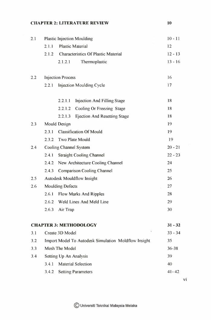
CHAPTER 2: LITERATURE REVIEW 10
2.1 Plastic Injection Moulding 10 - 11
2.1.1 Plastic Material 12
2.1.2 Characteristics Of Plastic Material 12 - 13
2.1.2.1 Thermoplastic 13 - 16
2.2 Injection Process 16
2.2.1 Injection Moulding Cycle 17
2.2.1.1 Injection And Filling Stage 18
2.2.1.2 Cooling Or Freezing Stage 18
2.2.1.3 Ejection And Resetting Stage 18
2.3 Mould Design 19
2.3.1 Classification Of Mould 19
2.3.2 Two Plate Mould 19
2.4 Cooling Channel System 20 - 21
2.4.1 Straight Cooling Channel 22 - 23
2.4.2 New Architecture Cooling Channel 24
2.4.3 Comparison Cooling Channel 25
2.5 Autodesk Mouldflow Insight 26
2.6 Moulding Defects 27
2.6.1 Flow Marks And Ripples 28
2.6.2 Weld Lines And Meld Line 29
2.6.3 Air Trap 30
CHAPTER3:METHODOLOGY 31-32
3.1 Create 3D Model 33 - 34
3.2 Import Model To Autodesk Simulation Moldflow Insight 35
3.3 Mesh The Model 36-38
3.4 Setting Up An Analysis 39
3.4.1 Material Selection 40
3.4.2 Setting Parameters 41- 42
vi
© Universiti Teknikal Malaysia Melaka
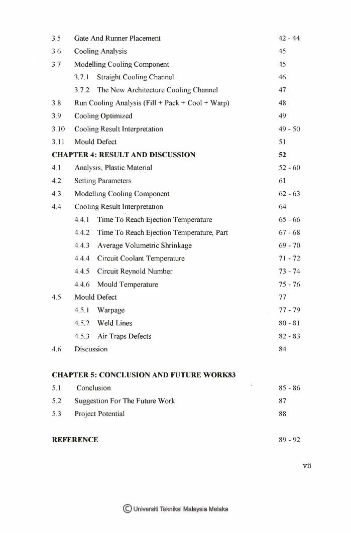
3.5 Gate And Runner Placement
3.6 Cooling Analysis
3.7 Modelling Cooling Component
3.7.1 Straight Cooling Channel
3.7.2 The New Architecture Cooling Channel
3.8 Run Cooling Analysis (Fill + Pack + Cool + Warp)
3.9 Cooling Optimized
3.10 Cooling Result Interpretation
3.11 Mould Defect
CHAPTER 4: RESULT AND DISCUSSION
4.1 Analysis, Plastic Material
4.2 Setting Parameters
4.3 Modelling Cooling Component
4.4 Cooling Result Interpretation
4.4.1 Time To Reach Ejection Temperature
4.4.2 Time To Reach Ejection Temperature, Part
4.4.3 Average Volumetric Shrinkage
4.4.4 Circuit Coolant Temperature
4.4.5 Circuit Reynold Number
4.4.6 Mould Temperature
4.5 Mould Defect
4.5.1 Warpage
4.5.2 Weld Lines
4.5.3 Air Traps Defects
4.6 Discussion
CHAPTER 5: CONCLUSION AND FUTURE WORK83
5.1
5.2
5.3
Conclusion
Suggestion For The Future Work
Project Potential
REFERENCE
© Universiti Teknikal Malaysia Melaka
42 - 44
45
45
46
47
48
49
49 - 50
51
52
52 -60
61
62 - 63
64
65 - 66
67 - 68
69- 70
71 - 72
73 - 74
75 - 76
77
77 - 79
80 - 81
82 - 83
84
85 - 86
87
88
89 - 92
vii
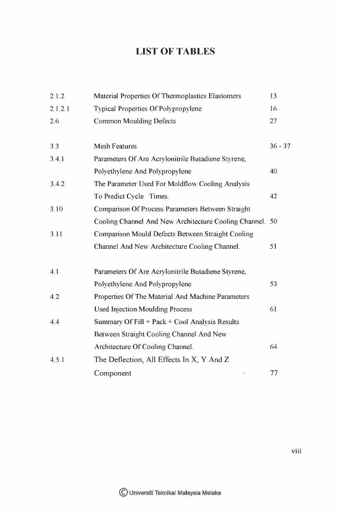
LIST OF TABLES
2.1.2 Material Properties Of Thermoplastics Elastomers 13
2.1.2. l Typical Properties Of Polypropylene 16
2.6 Common Moulding Defects 27
3.3 Mesh Features 36- 37
3.4.1 Parameters Of Are Acrylonitrile Butadiene Styrene,
Polyethylene And Polypropylene 40
3.4.2 The Parameter Used For Moldflow Cooling Analysis
To Predict Cycle Times. 42
3.10 Comparison Of Process Parameters Between Straight
Cooling Channel And New Architecture Cooling Channel. 50
3.11 Comparison Mould Defects Between Straight Cooling
Channel And New Architecture Cooling Channel. 51
4.1 Parameters Of Are Acrylonitrile Butadiene Styrene,
Polyethylene And Polypropylene 53
4.2 Properties Of The Material And Machine Parameters
Used Injection Moulding Process 61
4.4 Summary Of Fill + Pack+ Cool Analysis Results
Between Straight Cooling Channel And New
Architecture Of Cooling Channel. 64
4.5.1 The Deflection, All Effects In X, Y And Z
Component 77
viii
© Universiti Teknikal Malaysia Melaka
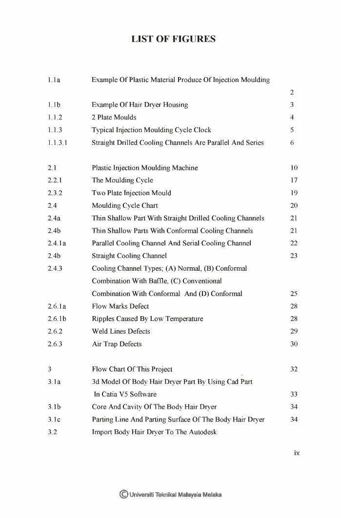
LIST OF FIGURES
l. la Example Of Plastic Material Produce Of Injection Moulding
2
l. lb Example Of Hair Dryer Housing 3
1.1.2 2 Plate Moulds 4
1.1.3 Typical Injection Moulding Cycle Clock 5
1.1.3.l Straight Drilled Cooling Channels Are Parallel And Series 6
2.1 Plastic Injection Moulding Machine 10
2.2.1 The Moulding Cycle 17
2.3.2 Two Plate Injection Mould 19
2.4 Moulding Cycle Chart 20
2.4a Thin Shallow Part With Straight Drilled Cooling Channels 21
2.4b Thin Shallow Parts With Conformal Cooling Channels 21
2.4.la Parallel Cooling Channel And Serial Cooling Channel 22
2.4b Straight Cooling Channel 23
2.4.3 Cooling Channel Types; (A) Normal, (B) Conformal
Combination With Baffle, (C) Conventional
Combination With Conformal And (D) Conformal 25
2.6.la Flow Marks Defect 28
2.6.lb Ripples Caused By Low Temperature 28
2.6.2 Weld Lines Defects 29
2.6.3 Air Trap Defects 30
3 Flow Chart Of This Project 32
3. la 3d Model Of Body Hair Dryer Part By Using Cad Part
In Cati a V 5 Software 33
3. lb Core And Cavity Of The Body Hair Dryer 34
3.lc Parting Line And Parting Surface Of The Body Hair Dryer 34
3.2 Import Body Hair Dryer To The Autodesk
ix
© Universiti Teknikal Malaysia Melaka
Simulation Moldflow Insight 35
3.3a Change From Solid Model To 3d Mesh 38
3.3b Meshing The Body Hair Dryer Using 3d Mesh 38
3.4 Setting Up An Analysis 39
3.5a Gate Types And Properties 43
3.5b Three Common Layout Of The Runner 43
3.5c Runner Sizing Depend On Plastic Material That Will Be Used 44
3.5d Example Of Gate And Runner Placement 44
3.7 Standard Modelling Tool 45
3.7.1 Straight Cooling Channe 46
3.7.2 New Architectures Cooling Channel 47
4.la Fill Time Result For Acrylonitrile Butadiene Styrene, ABS 54
4.lb Fill Time Result For Polyethylene, PE 55
4.lc Fill Time Result For Polypropylene, PP 55
4.ld Pressure At End Of Fill Result Of Acrylonitrile
Butadiene Styrene, ABS 56
4.le Pressure At End Of Fill Result Of Polyethylene,
PE 57
4.lf Pressure At End Of Fill Result Of Polypropylene, PP 57
4.lg Volumetric Shrinkage Result For Acrylonitrile
Butadiene Styrene, ABS 58
4. lh Volumetric Shrinkage Result For Polyethylene, PE 59
4. li Volumetric Shrinkage Result For Polypropylene, PP 59
4.1.1 Comparison Between Acrylonitrile Butadiene Styrene,
Polyethylene And Polypropylene Based On Parameters Of Fill Time,
Injection Pressure And Volumetric Shrinkage 60
4.3a Straight Cooling Channel With 3d Mesh 62
4.3b New Architecture Cooling Channel With 3d Mesh 63
4.4.la Time To Reach Ejection Temperature Strainght Cooling Channel 65
4.4.1 b Time To Reach Ejection Temperature New Architecture Cooling
Channel 66
4.4.2a Time To Reach Ejection Temperature, Part Of Straight Cooling
x
© Universiti Teknikal Malaysia Melaka
Channel 67
4.4.2b Time To Reach Ejection Temperature, Part Of The New
Architecture Cooling Channel. 68
4.4.2.1 Comparison Between Straight Cooling Channel And The New
Architecture Cooling Channel Based On The Time To Reach
Ejection Temperature And Time To Reach Part Ejection
Temperature 68
4.4.3a Volumetric Shrinkage Straight Cooling Channel 69
4.4.3b Volumetric Shrinkage New Architecture Cooling Channel 70
4.4.3.1 Comparison Of Average Volumetric Shrinkage Between Straight
And New Architecture Cooling Channel 70
4.4.4a Circuit Coolant Temperature Straight Cooling Channel 71
4.4.4b Circuit Coolant Temperature New Architecture Cooling Channel. 72
4.4.4.1 Comparison Of Circuit Coolant Channel 72
4.4.5a Circuit Reynolds Number Straight Cooling Channel 74
4.4.5b Circuit Reynolds Number New Architecture Cooling Channel 74
4.4.6a The Mould Temperature Of Straight Cooling Channel 75
4.4.6b The Mould Temperature Of The New Architecture
Cooling Channel 76
4.4.6.1 Comparison Of Mould Temperature 76
4.5.la The Deflection, All Effects ln X, Y And Z Component
of Straight Cooling Channel 78
4.5.lb The Deflection, All Effects In X , Y And Z
Component of The New Architecture Cooling Channel 79
4.5.2a Weld Lines And Meld Lines Defect In The
Straight Cooling Channel. 80
4.5.2b Weld Lines And Meld Lines Defect In The New Architecture
Of Cooling Channel. 81
4.5.3a Air Traps Defects ln The Straight Cooling Channel 82
4.5 .3b Air Traps Defects ln The New Architecture Cooling Channel 8
xi
© Universiti Teknikal Malaysia Melaka

ABS
PE
pp
IM
MPI
LIST OF ABBREVIATIONS, SYMBOLS AND
NOMENCLATURE
Acrylonitrile Butadiene Styrene
Polyethylene
Polypropylene
Injection Moulding
Moldflow Plastic lnsight software
© Universiti Teknikal Malaysia Melaka
xii
CHAPTERl
INTRODUCTION
This thesis proposes a new architecture for cooling channel of injection
moulding. This chapter presents the background of plastic injection moulding
and the research objectives to design a new architecture of cooling channel and
simulated by using Autodesk Simulation Moldflow insight 2014 and to compare
between conventional straight cooling channel and the new architecture of the
cooling channel.
1.1 Project Background
1.1.1 Plastic Injection moulding
Nowadays, injection moulding product has been extensively used in the daily
application, such as household appliances, industrial field, toys, medical device,
electronics, computer, communication, auto parts and also in the sport equipment.
Besides, the plastic material has the advantages such as lightweight, leakproof,
durable, flexible and non-breakable compared to other material which also being
used for such applications.
1
© Universiti Teknikal Malaysia Melaka
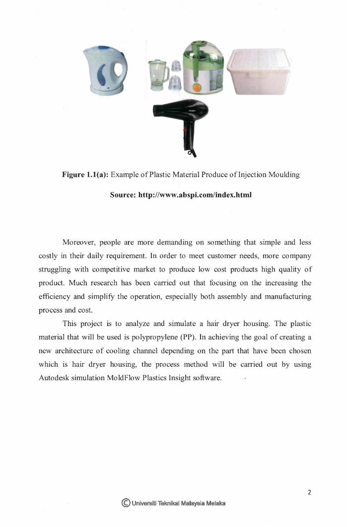
Figure 1.l(a): Example of Plastic Material Produce oflnjection Moulding
Source: http://www.abspi.com/index.htmJ
Moreover, people are more demanding on something that simple and less
costly in their daily requirement. In order to meet customer needs, more company
struggling with competitive market to produce low cost products high quality of
product. Much research has been carried out that focusing on the increasing the
efficiency and simplify the operation, especially both assembly and manufacturing
process and cost.
This project is to analyze and simulate a hair dryer housing. The plastic
material that will be used is polypropylene (PP). In achieving the goal of creating a
new architecture of cooling channel depending on the part that have been chosen
which is hair dryer housing, the process method will be carried out by using
Autodesk simulation MoldFlow Plastics Insight software.
2
© Universiti Teknikal Malaysia Melaka
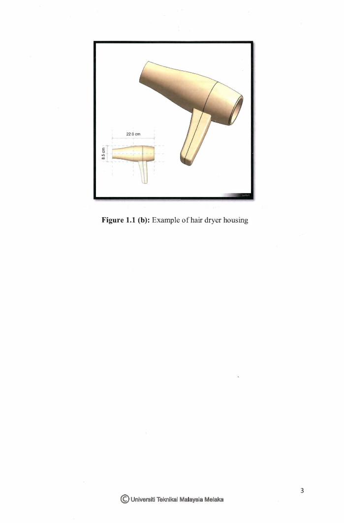
Figure 1.1 (b): Example of hair dryer housing
3 © Universiti Teknikal Malaysia Melaka
1.1.2. 2 Plate Mould
/ Sprv• buahl"9
FIG. 8.4 r •-ri..1 Ill llOfl mc. IJ
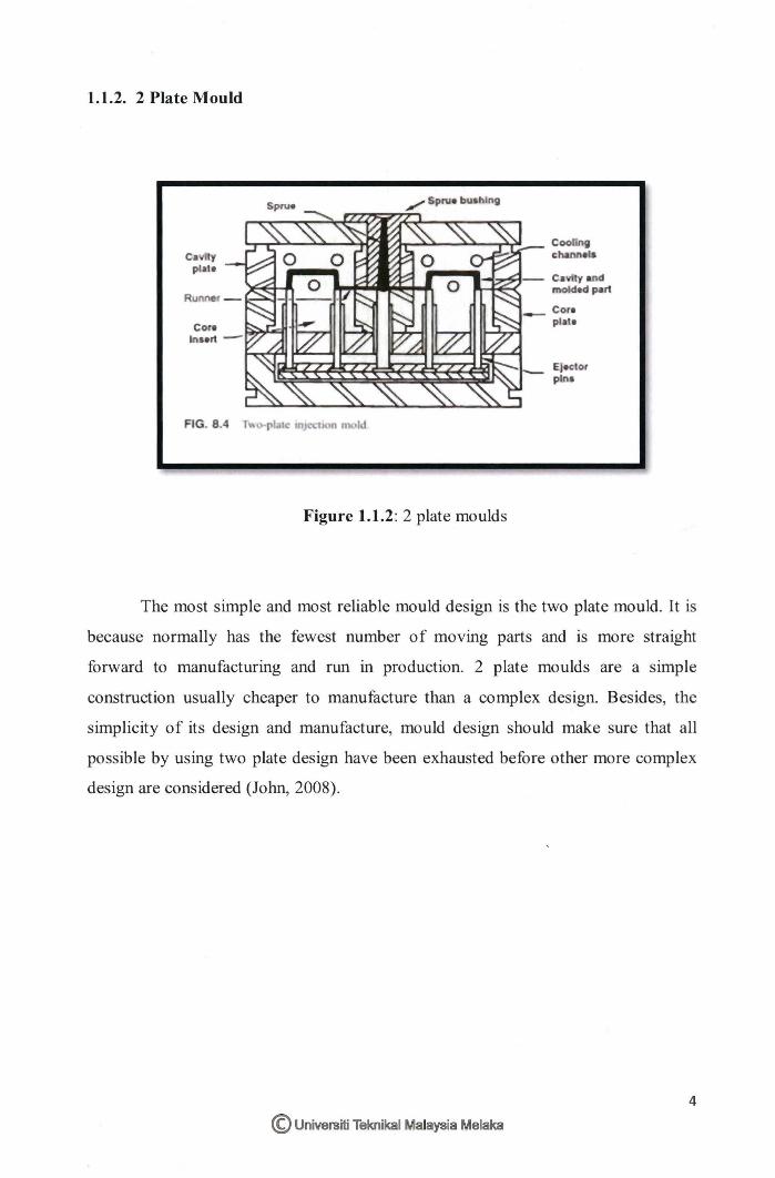
Figure 1.1.2: 2 plate moulds
Ejector pin•
The most simple and most reliable mould design is the two plate mould. It is
because normally has the fewest number of moving parts and is more straight
forward to manufacturing and run in production. 2 plate moulds are a simple
construction usually cheaper to manufacture than a complex design. Besides, the
simplicity of its design and manufacture, mould design should make sure that all
possible by using two plate design have been exhausted before other more complex
design are considered (John, 2008).
4
© Universiti Teknikal Malaysia Melaka
1.1.3. Cooling Channel
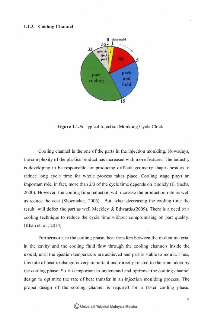
Figure 1.1.3: Typical Injection Moulding Cycle Clock
Cooling channel is the one of the parts in the injection moulding. Nowadays,
the complexity of the plastics product has increased with more features. The industry
is developing to be responsible for producing difficult geometry shapes besides to
reduce long cycle time for whole process takes place. Cooling stage plays an
important role, in fact , more than 2/3 of the cycle time depends on it solely (E. Sachs,
2000). However, the cooling time reduction will increase the production rate as well
as reduce the cost (Shoemaker, 2006). But, when decreasing the cooling time the
result will defect the part as well Meckley & Edwards,(2009). There is a need of a
cooling technique to reduce the cycle time without compromising on part quality.
(Khan et. al. , 2014)
Furthermore, in the cooling phase, heat transfers between the molten material
in the cavity and the cooling fluid flow through the cooling channels inside the
mould, until the ejection temperature are achieved and part is stable to mould. Thus,
this rate of heat exchange is very important and directly related to the time taken by
the cooling phase. So it is important to understand and optimize the cooling channel
design to optimize the rate of heat transfer in an injection moulding process. The
proper design of the cooling channel is required for a faster cooling phase.
5
© Universiti Teknikal Malaysia Melaka
Historically, the cooling channels have been created by drilling several straight holes
cooling channels inside the mould core and cavity. Such type of cooling channels is
called as Conventional Cooling Channels (khan et. al., 2014). However the cooling
process in conventional Cooling Channels is too long because of nonuniform cooling
of the part. If the part's temperature can be reduced more quickly and uniformly, it
will shorten the cooling time without compromising on part quality because nearly
uniform temperatures can be held in part by using conformal cooling Meckley &
Edwards, (2009).
1.1.3.1. Straight Cooling Channel
I I
\. J
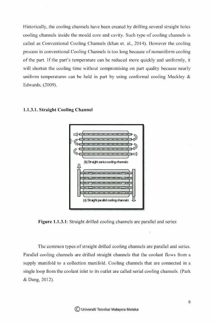
Figure 1.1.3.1 : Straight drilled cooling channels are parallel and series
The common types of straight drilled cooling channels are parallel and series.
Parallel cooling channels are drilled straight channels that the coolant flows from a
supply manifold to a collection manifold. Cooling channels that are connected in a
single loop from the coolant inlet to its outlet are called serial cooling channels. (Park
& Dang, 2012).
6
© Universiti Teknikal Malaysia Melaka
1.1.3.2. New architecture Cooling channel
Research in new architecture cooling channel, the shape of cooling channel
has conformed to the shape of the cavity in the mold. Research of conformal cooling
channel is depending on simulation studies. Konsulova-Bakalova has used thermal
simulation software, SolidWorks Simulation, and compared conformal cooling
channels with circular and elliptical cross-sections. He has concluded that the cooling
time of the part has been optimized by using conformal cooling channels and results
translate a reduction in production cycle time and increase in the quality of the parts
("Application of solidwoks simulation for the design of the cooling system for
injection molding").
1.1.4. Project Briefing
This project aims is to optimize the cooling channel for Plastic Injection
Mould (2 Plate mould). Specifically for conventional straight cooling channel and
create new architecture of cooling channel. Nowadays, global industries are
increasing with the trend of consumer product designed that is getting smaller. Most
of the cover is made from plastic which was produced by using an injection
moulding process. It is difficult to control the defect on the part. Therefore, this study
is performed purposely to evaluate the performance of the new architecture of
cooling channel compared to the straight drilled cooling channel in order to minimize
the defect on the part . Moreover, the result can get by using simulation through
Autodesk Moldflow to get the optimization of cooling channel. However, cooling
design of plastic injection mould is important because it not only affects part quality,
but also the injection moulding cycle time.
© Universiti Teknikal Malaysia Melaka 7
1.2. Problem Statement
In every injection moulding process, the problem occurs after the molten
plastic melts turns to solidify. Several defects will appear which will affect the
performance of the part. Certain design of the cooling channel is not suitable to the
curve part if using the straight cooling channel. The major problem needs to be
concerned is the product defect. The focus should be on the cooling process of the
product that is during cooling analysis and parameter of the cooling channel for the
part which can reduce the defect. Moreover, the material also plays an important role
in reducing the defects that might appear on the part. The aim of determining which
cooling system configuration is appropriate for this part providing uniform cooling,
minimum cycle time, less warpage and shrinkage. From the research the straight
cooling channel takes a long time of cycle time, while conformal cooling channel
design gives better cycle time, which ultimately increases production rate as well as
fatigue life of the mould. It is important to determine a method to get the best result
for the future mould of this part to minimize defects.
1.3. Objective
1. To design a new architecture of cooling channel and simulated by using
Autodesk Simulation Mold flow insight 2014
2. To compare between conventional straight cooling channel and the new
architecture of the cooling channel.
8
© Universiti Teknikal Malaysia Melaka