design and simulation automobile active … · management centre dengan syarat-syarat kegunaan...
TRANSCRIPT
DESIGN AND SIMULATION AUTOMOBILE ACTIVE SUSPENSION SYSTEM
MOHD ASQALANI BIN NAHARUDIN
UNIVERSITI MALAYSIA PAHANG
UNIVERSITI MALAYSIA PAHANG
BORANG PENGESAHAN STATUS TESIS
JUDUL: DESIGN AND SIMULATION AUTOMOBILE ACTIVE SUSPENSION SYSTEM
SESI PENGAJIAN: 2007/2008
Saya MOHD ASQALANI BIN NAHARUDIN (HURUF BESAR)
mengaku membenarkan tesis (PSM/Sarjana/Doktor Falsafah)* ini disimpan di Knowledge Management Centre dengan syarat-syarat kegunaan seperti berikut:
1. Tesis adalah hakmilik Universiti Malaysia Pahang. 2. Knowledge Management Centre dibenarkan membuat salinan untuk tujuan pengajian sahaja. 3. Perpustakaan dibenarkan membuat salinan tesis ini sebagai bahan pertukaran antara
institusi pengajian tinggi. 4. **Sila tandakan ( )
SULIT (Mengandungi maklumat yang berdarjah keselamatan atau kepentingan Malaysia seperti yang termaktub di dalam AKTA RAHSIA RASMI 1972) TERHAD (Mengandungi maklumat TERHAD yang telah ditentukan oleh Organisasi/badan dimana penyelidikan dijalankan)
TIDAK TERHAD Disahkan oleh
___________________________________ ___________________________________ (TANDATANGAN PENULIS) (TANDATANGAN PENYELIA) Alamat Tetap: Nama Penyelia: NO 466 BLOK 21 (F) KERATONG 3 MR. MOHD SHAHRIR MOHD SANI
26900 BDR TUN RAZAK PAHANG.
Tarikh: ____________________________ Tarikh: ____________________________ CATATAN: * Potong yang tidak berkenaan ** Jika tesis ini SULIT atau TERHAD, sila lampirkan surat daripada pihak berkuasa/organisasi berkenaan dengan menyatakan sekali sebab dan tempoh tesis ini perlu dikelaskan sebagai SULIT atau TERHAD Tesis dimaksudkan sebagai tesis bagi Ijazah Doktor Falsafah dan Sarjana secara penyelidikan, atau disertasi bagi pengajian secara kerja kursus dan penyelidikan, atau Laporan Projek Sarjana Muda (PSM)
DESIGN AND SIMULATION AUTOMOBILE ACTIVE SUSPENSION SYSTEM
MOHD ASQALANI BIN NAHARUDIN
A report submitted in partial fulfilment of the requirements for the award of the degree of
Bachelor of Mechanical Engineering with Automotive Engineering
Faculty of Mechanical Engineering UNIVERSITI MALAYSIA PAHANG
NOVEMBER 2008
SUPERVISOR’S DECLARATION
We hereby declare that we have checked this project and in our opinion this project is
satisfactory in terms of scope and quality for the award of the degree of Bachelor of
Mechanical Engineering with Automotive
Signature
Name of Supervisor:
Position:
Date:
Signature
Name of Panel:
Position:
Date:
STUDENT’S DECLARATION
I hereby declare that the work in this thesis is my own except for quotations and
summaries which have been duly acknowledged. The thesis has not been accepted for
any degree and is not concurrently submitted for award of other degree.
Name: Mohd Asqalani Bin Naharudin
ID Number: MH05058
Date:
ACKNOWLEDGEMENTS
In the name of ALLAH SWT, the most Gracious, who has given me the strength
and ability to complete this study. All perfect praises belong to ALLAH SWT, lord of
the universe. May His blessing upon the prophet Muhammad SAW and member of his
family and companions.
I gratefully acknowledge the co-operation of En. Mohd Shahrir Mohd Sani and
Dr. Wan Azhar bin Wan Yusoff who has provided me with the reference, guidance,
encouragement and support in completing this thesis. All the regular discussion sessions
that we had throughout the period of study have contributed to the completion of this
project.
Thank you to my classmate for providing an enjoyable study environment.
Finally, I would like to thank my family for their encouragement, support and patience.
ABSTRACT
The purpose of this project is to design and simulate a semi-active suspension system for
a quarter car model by controlling two input, spring stiffness, ks, and damper rate, bs.
The performance of this system will be compared with the passive suspension system.
There are two parameters to be observed in this study namely, the sprung mass
acceleration and the suspension distortion. The performance of this system will be
determined by performing computer simulations using the MATLAB and SIMULINK
toolbox. For the first experiment, the damper rate was set to constant while spring
stiffness was set from 10507 N/m to 131345 N/m. at lower spring stiffness leads
improvement in ride quality but increased the suspension distortion at lower time. At
second experiment, the spring stiffness was set to constant while the damper rate was
from 1000 N.sec/m to 1400 N.sec/m. Increases in damper rate improve the ride quality
but slower roll-off will occurred. In the third experiment, the damper rate value was set
to maximum while spring stiffness was set to minimum to achieve optimal performance.
The simulation results show that the semi-active system could provide significant
improvements in the ride quality and road handling compare with the passive system.
ABSTRAK
Tujuan projek ini adalah mereka bentuk dan simulasi satu separa aktif sistem suspensi
untuk satu perempat model kereta dengan kawalan dua input, melompat kekakuan, ks,
dan kadar penyerap, bs. Prestasi sistem ini akan dibanding dengan sistem suspensi pasif.
Terdapat dua parameter untuk diperhatikan dalam kajian ini yakni, pecutan besar-
besaran dan melompat dan herotan suspensi. Prestasi sistem ini akan ditentukan dengan
menggunakan simulasi komputer menggunakan peti alat MATLAB dan SIMULINK.
Untuk eksperiment pertama, kadar penyerap dijadikan pemalar manakala nilai kadar
keanjalan spring dari 10507 N/m ke 131345 N/m. Pada nilai keanjalan spring rendah
memberikan peningkatan dalam kualiti pemanduan tetapi herotan suspense meninggi
pada kemudian masa. Bagi eksperimen kedua, keanjalan spring dijadikan pemalar
manakala nilai kadar penyerap dari 1000 N.sec/m ke 1400 N.sec/m. Kenaikan pada
kadar penyerapmeningkatkan kualiti pemanduan tetapi ‘slower roll-off’ akan terjadi.
Dalam eksperimen ketiga, kadar penyerap menggunakan nilai maksimum manakala
keanjalan spring menggunakan nilai minimum untuk mendapat prestasi optimum. Hasil
simulasi menunjukkan bahawa separa aktif sistem boleh memberikan peningkatan
penting dalam kualiti pemanduan dan pengendalian kenderaan berbanding sistem pasif.
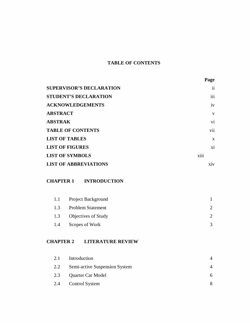
TABLE OF CONTENTS
Page
SUPERVISOR’S DECLARATION ii
STUDENT’S DECLARATION iii
ACKNOWLEDGEMENTS iv
ABSTRACT v
ABSTRAK vi
TABLE OF CONTENTS vii
LIST OF TABLES x
LIST OF FIGURES xi
LIST OF SYMBOLS xiii
LIST OF ABBREVIATIONS xiv
CHAPTER 1 INTRODUCTION
1.1 Project Background 1
1.3 Problem Statement 2
1.3 Objectives of Study 2
1.4 Scopes of Work 3
CHAPTER 2 LITERATURE REVIEW
2.1 Introduction 4
2.2 Semi-active Suspension System 4
2.3 Quarter Car Model 6
2.4 Control System 8
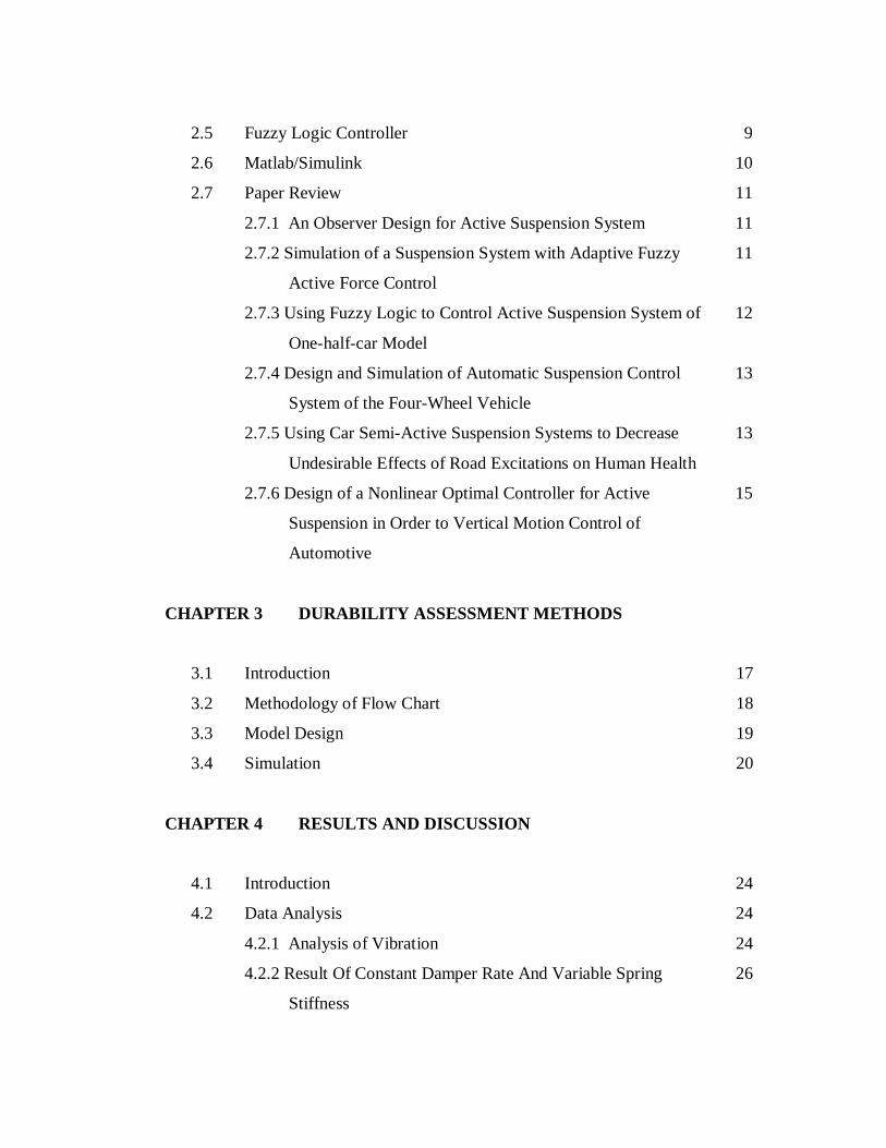
2.5 Fuzzy Logic Controller 9
2.6 Matlab/Simulink 10
2.7 Paper Review 11
2.7.1 An Observer Design for Active Suspension System 11
2.7.2 Simulation of a Suspension System with Adaptive Fuzzy
Active Force Control
11
2.7.3 Using Fuzzy Logic to Control Active Suspension System of
One-half-car Model
12
2.7.4 Design and Simulation of Automatic Suspension Control
System of the Four-Wheel Vehicle
13
2.7.5 Using Car Semi-Active Suspension Systems to Decrease
Undesirable Effects of Road Excitations on Human Health
13
2.7.6 Design of a Nonlinear Optimal Controller for Active
Suspension in Order to Vertical Motion Control of
Automotive
15
CHAPTER 3 DURABILITY ASSESSMENT METHODS
3.1 Introduction 17
3.2 Methodology of Flow Chart 18
3.3 Model Design 19
3.4 Simulation 20
CHAPTER 4 RESULTS AND DISCUSSION
4.1 Introduction 24
4.2 Data Analysis 24
4.2.1 Analysis of Vibration 24
4.2.2 Result Of Constant Damper Rate And Variable Spring
Stiffness
26
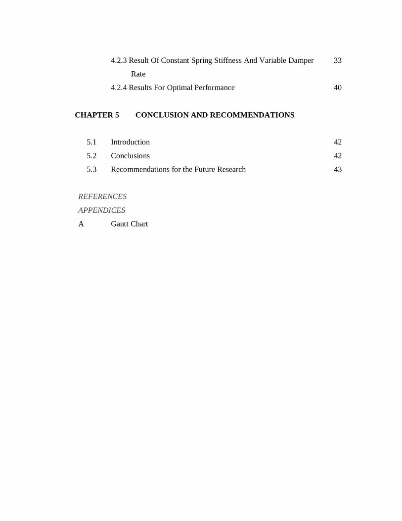
4.2.3 Result Of Constant Spring Stiffness And Variable Damper
Rate
33
4.2.4 Results For Optimal Performance 40
CHAPTER 5 CONCLUSION AND RECOMMENDATIONS
5.1 Introduction 42
5.2 Conclusions 42
5.3 Recommendations for the Future Research 43
REFERENCES
APPENDICES
A Gantt Chart
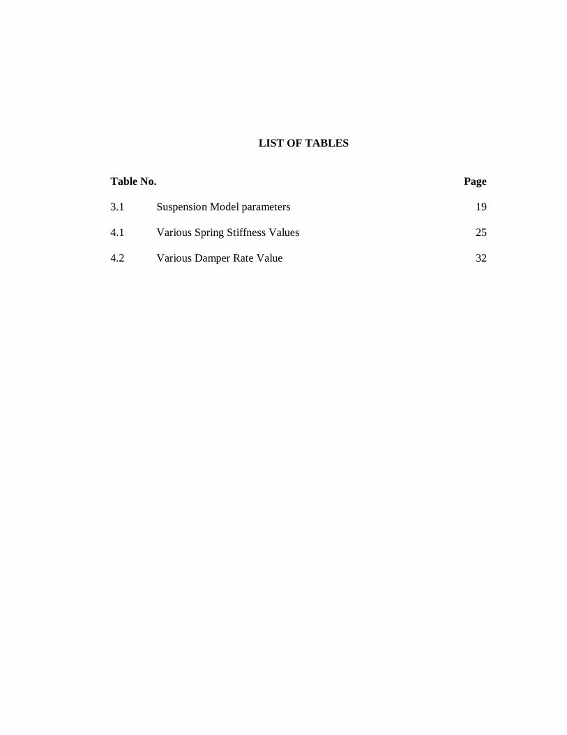
LIST OF TABLES
Table No. Page 3.1 Suspension Model parameters 19 4.1 Various Spring Stiffness Values 25 4.2 Various Damper Rate Value 32
LIST OF FIGURES
Figure No. Page 2.1 Schematic of a variable damper 5 2.2 Commercial linear MR fluid-based damper 5 2.3 Schematic of semi-active suspension system 6 2.4 Quarter-car active suspension system 7 2.5 One half car model 12 3.1 Flow Chart 18 3.2 Two DOF suspension model 19 3.3 Block diagram of overall suspension system 21 3.4 Block diagram for semi-active suspension system 22 3.5 Block diagram for passive suspension system 23 4.1 Sprung mass acceleration 25 4.2 Suspension Distortion 25 4.3 Sprung mass acceleration for ks=10507 N/m 27 4.4 Suspension distortion for ks=10507 N/m 27 4.5 Sprung mass acceleration for ks=21890 N/m 28 4.6 Suspension distortion for ks=21890 N/m 28 4.7 Sprung mass acceleration for ks=35025 N/m 29 4.8 Suspension distortion for ks=35025 N/m 29
4.9 Sprung mass acceleration for ks=56916 N/m 30 4.10 Suspension distortion for ks=56916 N/m 30 4.11 Sprung mass acceleration for ks=78807 N/m 31 4.12 Suspension distortion for ks=78807 N/m 31 4.13 Sprung mass acceleration for ks=131345 N/m 32 4.14 Suspension distortion for ks=131345 N/m 32 4.15 Sprung mass acceleration for bs =1000 N.sec/m 34 4.16 Suspension distortion for bs =1000 N.sec/m 35 4.17 Sprung mass acceleration for bs =1100 N.sec/m 35 4.18 Suspension distortion for bs =1100 N.sec/m 36 4.19 Sprung mass acceleration for bs =1200 N.sec/m 36 4.20 Suspension distortion for bs =1200 N.sec/m 37 4.21 Sprung mass acceleration for bs =1300 N.sec/m 37 4.22 Suspension distortion for bs =1300 N.sec/m 38 4.23 Sprung mass acceleration for bs =1400 N.sec/m 38 4.24 Suspension distortion for bs =1400 N.sec/m 39 4.25 Sprung mass acceleration for optimal performance 40 4.26 Figure 4.26 Suspension distortion for optimal performance 41
LIST OF SYMBOLS
퓏 Sprung mass displacement 퓏 Unsprung mass displacement 퓏 Road profile input 퓂 Sprung mass 퓂 Unsprung mass 푘 Spring stiffness 푏 Damper rate 푘 Tire stiffness
LIST OF ABBREVIATIONS
AF adaptive fuzzy AFC active force control DOF degree-of-freedom FLC FUZZY LOGIC CONTROLLER HJB Hamilton-Jacobi-Belman LQ Linear Quadratic LQG Linear Quadratic Gaussian LQR Linear Quadratic Regulator MR magneto rheological ONNC Optimal Neural Network Controller PI proportional-integral PID Proportional Integral Derivative
CHAPTER 1
INTRODUCTION
1.1 PROJECT BACKGROUND
A car suspension system is the mechanism that physically separates the car body
from the wheels of the car. The performance of the suspension system has been greatly
increased due to increasing vehicle capabilities. In order to achieve a good suspension
system, several performance characteristics have to be considered [1]. These
characteristics deal with the regulation of body movement, the regulation of suspension
movement and the force distribution. Ideally the suspension should isolate the body from
road disturbances and inertial disturbances associated with cornering and braking or
acceleration. The suspension must also be able to minimize the vertical force transmitted
to the passengers for their comfort.
This objective can be achieved by minimizing the vertical car body acceleration.
An excessive wheel travel will result in non-optimum attitude of tire relative to the road
that will cause poor handling and adhesion. Furthermore, to maintain good handling
characteristic, the optimum tire-to-road contact must be maintained on four wheels. In
conventional suspension system, these characteristics are conflicting and do not meet all
conditions. Automotive researchers have studied the suspension on the system
extensively through both analysis and experiments. The main goal of the study is to
improve the traditional design trade-off between ride and road handling by directly
controlling the suspension forces to suit with the performance characteristics .
Suspension systems can be categorized as passive, semi-active, and full-active
suspensions system. Passive system consists of conventional components with spring
and damping (shock absorber) properties which are time-invariant. Passive element can
only store energy for some portion of a suspension cycle (springs) or dissipate energy
(shock absorbers). No external energy is directly supplied to this type of suspension.
Semi-active suspensions contain spring and damping elements, the properties of which
can be changed by an external control. A signal or external power is supplied to these
systems for purpose of changing the properties. Full-active suspensions incorporate
actuators to generate the desired forces in the suspension. The actuators are normally
hydraulic cylinders. External power is required to operate the system .
1.2 PROBLEM STATEMENT
The suspension system that commonly applied on the vehicle is a passive
suspension system in which its spring stiffness and dumping value is constant. In the
passive suspension system it dumping system has not yet gives a high performance
where its vibration amplitude still high and the time required terminating the vibration is
quite longer. To overcome this condition, it is then introduced a semi-active suspension
and active suspension system. Unfortunately the active suspension system requires
larger energy and less economizly, so then the semi-active suspension become a better
choice to keep the quality of the car comfortable on any road condition.
1.3 OBJECTIVES OF STUDY
The objectives of this research are as follows:
a) To design an active suspension for a quarter car model
b) To simulate the designed active suspension system by manipulating 2
parameters; spring stiffness and damper rate.
1.4 SCOPES OF WORK
The scopes of work for this study are as follows:
a) Study on semi-active suspension system for a quarter car model and the Fuzzy
Logic controller used in the system
b) Design the system by using MATLAB/SIMULINK
c) Simulate the system using MATLAB/SIMULINK
CHAPTER 2
LITERATURE REVIEW
2.1 INTRODUCTION
With a reference from various source such as books, journal, notes, thesis and
internet literature review has been carry out to collect all information related to this
project. This chapter discussed about semi-active suspension system for a quarter car
model that will be designed and simulated by using software Matlab/Simulink.
2.2 SEMI-ACTIVE SUSPENSION SYSTEM
A semi-active suspension system utilizes a variable damper or other variable
dissipation component in the automotive suspension. An example of a variable dissipater
is a twin tube viscous damper in which the damping coefficient can be varied by
changing the diameter of the orifice in a piston.
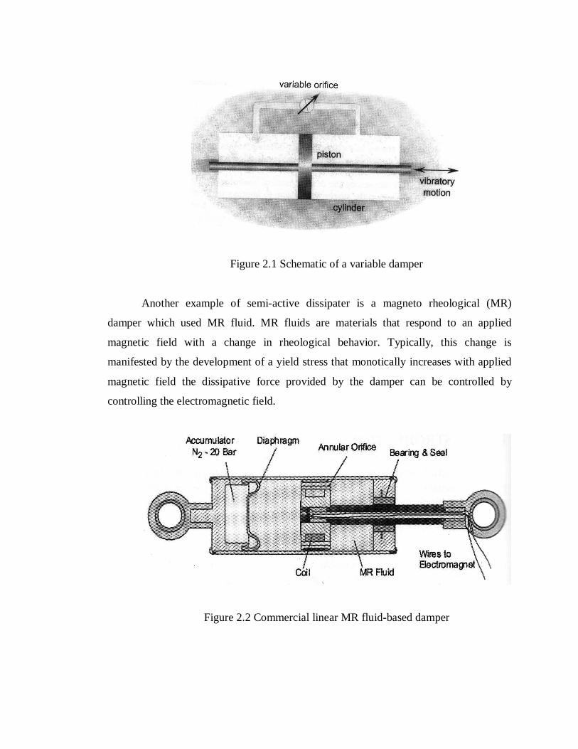
Figure 2.1 Schematic of a variable damper
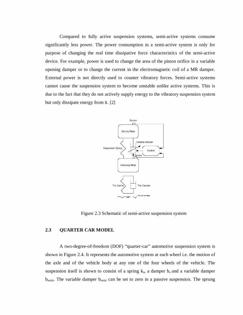
Another example of semi-active dissipater is a magneto rheological (MR)
damper which used MR fluid. MR fluids are materials that respond to an applied
magnetic field with a change in rheological behavior. Typically, this change is
manifested by the development of a yield stress that monotically increases with applied
magnetic field the dissipative force provided by the damper can be controlled by
controlling the electromagnetic field.
Figure 2.2 Commercial linear MR fluid-based damper
Compared to fully active suspension systems, semi-active systems consume
significantly less power. The power consumption in a semi-active system is only for
purpose of changing the real time dissipative force characteristics of the semi-active
device. For example, power is used to change the area of the piston orifice in a variable
opening damper or to change the current in the electromagnetic coil of a MR damper.
External power is not directly used to counter vibratory forces. Semi-active systems
cannot cause the suspension system to become unstable unlike active systems. This is
due to the fact that they do not actively supply energy to the vibratory suspension system
but only dissipate energy from it. [2]
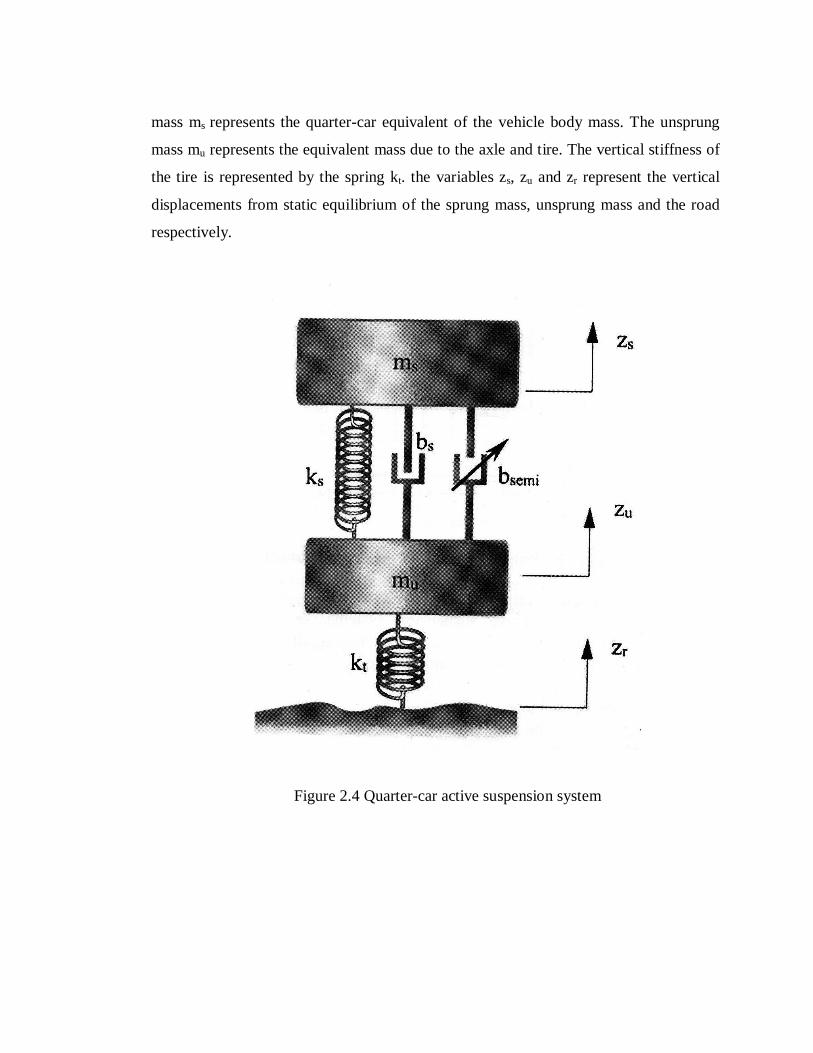
Figure 2.3 Schematic of semi-active suspension system
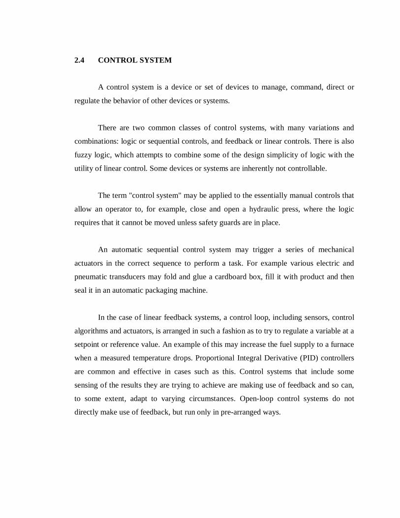
2.3 QUARTER CAR MODEL
A two-degree-of-freedom (DOF) “quarter-car” automotive suspension system is
shown in Figure 2.4. It represents the automotive system at each wheel i.e. the motion of
the axle and of the vehicle body at any one of the four wheels of the vehicle. The
suspension itself is shown to consist of a spring ks, a damper bs and a variable damper
bsemi. The variable damper bsemi can be set to zero in a passive suspension. The sprung
mass ms represents the quarter-car equivalent of the vehicle body mass. The unsprung
mass mu represents the equivalent mass due to the axle and tire. The vertical stiffness of
the tire is represented by the spring kt. the variables zs, zu and zr represent the vertical
displacements from static equilibrium of the sprung mass, unsprung mass and the road
respectively.
Figure 2.4 Quarter-car active suspension system
2.4 CONTROL SYSTEM
A control system is a device or set of devices to manage, command, direct or
regulate the behavior of other devices or systems.
There are two common classes of control systems, with many variations and
combinations: logic or sequential controls, and feedback or linear controls. There is also
fuzzy logic, which attempts to combine some of the design simplicity of logic with the
utility of linear control. Some devices or systems are inherently not controllable.
The term "control system" may be applied to the essentially manual controls that
allow an operator to, for example, close and open a hydraulic press, where the logic
requires that it cannot be moved unless safety guards are in place.
An automatic sequential control system may trigger a series of mechanical
actuators in the correct sequence to perform a task. For example various electric and
pneumatic transducers may fold and glue a cardboard box, fill it with product and then
seal it in an automatic packaging machine.
In the case of linear feedback systems, a control loop, including sensors, control
algorithms and actuators, is arranged in such a fashion as to try to regulate a variable at a
setpoint or reference value. An example of this may increase the fuel supply to a furnace
when a measured temperature drops. Proportional Integral Derivative (PID) controllers
are common and effective in cases such as this. Control systems that include some
sensing of the results they are trying to achieve are making use of feedback and so can,
to some extent, adapt to varying circumstances. Open-loop control systems do not
directly make use of feedback, but run only in pre-arranged ways.