modelling, simulation and experimental verification of …umpir.ump.edu.my/7629/1/modelling,...
TRANSCRIPT
MODELLING, SIMULATION AND EXPERIMENTAL VERIFICATION OF A SEMI ACTIVE ABSORBER SYSTEM
MOHAMAD NASRUL BIN MOHD NASIR
Thesis submitted in partial fulfilment of the requirements for the award of the degree of
Bachelor ofMechatronic Engineering
Faculty ofManufacturing Engineering UNIVERSITI MALAYSIA PAHANG
SEPTEMBER 2013
Vll
ABSTRACT
The vehicle suspension system is responsible for driving comfort and safety as the suspension caries the vehicle body and transmits all forces between the body and the road. The vehicle suspension system consists of wishbones, the spring and the shock absorber to transmit and also filter all forces between the body and road. The spring carries the body mass and isolates the body from road disturbances and thus contributes to drive comfort, while absorber function is to slow down the oscillation experienced by the spring from being transferred into vehicle body. The purpose of his study is to modelling, simulation and experimental verification of a semi active absorber system, for the good absorber it must contain the criteria where it can split between the body and wheel. In order to obtain the characteristic, the fixed design of the suspension system should be change by controlling fluid flow that move from compression and rebound chamber. The experimental result showed that, when increasing the size of valve opening the value of pressure inside chamber also decreases. At the end of the project, the semi active absorber system is developed and can be used to solve the conflict experienced by automotive manufacturer either to choose between passenger satisfaction and cost.
V111
ABSTRAK
Sistem suspensi kenderaan bertanggungjawab memberikan keselesaan dan keselamatan kerana sistem suspensi berfungsi menampung badan kenderaan dan mengalihkan semua tenaga berlebihan di antara badan kenderaan dan tayar kenderaan. Sistem suspensi kenderaan merangkumi tiga bahagian iaitu "wishbones", spring dan penyerap hentakan, ia bertujuan untuk mengalihkan dan menapis semua tenaga diantara badan kenderaan dan jalanraya. Spring bertujuan untuk membawa berat kenderaan dan mengasingkan badan kenderaan apabila melalui halangan jalan seterusnya menyumbang kepada keselesaan dalam pemanduan, sementara penyerap hentakan berfungsi untuk memperlahankan getaran yang dialami oleh spring sebelum dialirkan kepada badan kenderaan. Tujuan ujikaji ini ialah untuk untuk memodelkan, mensimulasikan dan mengeksperimentkan kesahihan tentang sistem suspensi separuh aktif, bagi sistem hentakan yang baik ia mestilah mempunyai fungsi dimana ia dapat menceraikan di antara bahagian badan kenderaan dengan bahagian tayar. Bagi memperolehi kriteria tersebut, rekaan yang kekal haruslah ditukar menjadi sistem yang boleh dikawal dengan cara mengawal pengaliran keluar masuk cecair di dalam ruang mampatan dan ruang pemulihan. Berdasarkan keputusan yang diperolehi, semakin bertambah saiz injap yang dibuka semakin berkurang tekanan di dalam injap tersebut. Kesimpulannya , sistem suspensi separa aktif ini dicipta dan boleh diaplikasikan untuk menyelesaikan krisis yang dihadapi oleh pengusaha kenderaan sama ada untuk memilih di antara kepuasan pelanggan mahupun kewangan.
IX
TABLE OF CONTENT
EXAMINER'S APPROVAL DOCUMENT 11
SUPERVISOR'S DECLARATION 111
STUDENT'S DECLARATION IV
DEDICATION v
ACKNOWLEDGEMENT VI
ABSTRACT Vll
ABSTRAK V111
TABLE OF CONTENT IX
LIST OF FIGURES Xll
LIST OF SYMBOLS XIV
LIST OF ABBREVIA TIVES XVll
CHAPTER! INTRODUCTION
1.1 Project Motivation 1
1.2 Project Background 2
1.3 Problem Statement 4
1.4 Project Objectives 6
1.5 Project Scopes 6
1.6 Report Organization 7
CHAPTER2 LITERATURE REVIEW
2.1 History Of Shock Absorber 9
2.2 Introduction 10
2.3 Basic Types Of Shock Absorber 12
2.4 Vehicle Model 15
2.4.1 Full Vehicle Model. 15 2.4.2 Quarter Vehicle Model. 17
2.5 Operating Speeds And Strokes
2.5.1 Drop Test 2.5.2 Free Drop Release 2.5.3 Ride Motions 2.5.4 Longitudinal Acceleration Transients 2.5.5 Lateral Transient (Roll)
2.6 Classification Of Suspension System
2.6.1 Passive System 2.6.2 Semi Active Suspension System 2.6.3 Active Suspension System
CHAPTER3 METHODOLOGY
3.1 PSM Flow Chart
3.2 Methodology Flow Chart
3.3 Introduction
3.3.1 Stage One 3.3.2 Stage Two 3.3.3 Stage Three 3.3.4 Stage Four 3.3.5 Stage Five
CHAPTER4 RESULT AND DISCUSSION
4.1 Introduction
4.2 Bleed Orifice Valve Adjustment
4.3 Simulation vs Real Result
4.4 Real Passive vs Semi Active No Hole Open
4.5 Semi Active Result
CHAPTERS CONCLUSION
5.1
5.2
Introduction
Conclusion and Recommendation
X
18
19 20 20 21 25
26
27 28 29
31
32
33
34 34 35 36 37
39
39
42
45
47
50
50
REFERENCES
APPENDICES
Xl
53
54
Xll
LIST OF FIGURES
Figure No. Title Page
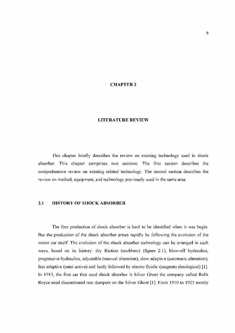
2.1 The Andre-Hartford scissor-action dry friction damper. 10
2.2 Conflict diagram 12
2.3 Dry-friction scissors damper on three quarter elliptic leaf springs 13
2.4 The Gabriel Snubber used a leather strap around sprung metal or 13 wooden blocks to give restraint in rebound only
2.5 The simple lever-arm damper can be reinforced to carry 14 suspension loads by lengthening the bearing rod
2.6 The Armstrong double telescopic lever arm damper 14
2.7 Full car model 16
2.8 Equation of motion. 16
2.9 The quarter car model. 18
2.10 Quarter car model equation. 18
2.11 Simple high drop analysis 19
2.12 Impact speed formula. 19
2.13 Speed when damper is removed 20
2.14 Formula for suspension bump velocity. 21
2.15 Suspension bump displacement. 22
2.16 Pitch moment 22
2.17 Angular stiffness 23
2.18 Longitudinal load transfer. 23
2.19 Associated pitch angle 23
2.20 Suspension deflection formula. 24
2.21 Natural frequency 24
X111
2.22 Estimated suspension bump velocity 25
2.23 Suspension roll angle. 25
2.24 Suspension deflection 26
2.25 Suspension velocity amplitude 26
2.26 Classification of suspension system. 27
3.1 Test rig 36
3.2 Inner side of damper system 37
4.1 Total flow valve 40
4.2 Bleed orifice beginning 41
4.3 Bleed orifice ends 41
4.4 Passive simulation and real result 43
4.5 Sapura testing parameter 43
4.6 Semi active simulation and real result. 44
4.7 Graph for rebound force vs. Speed 46
4.8 Graph for compression force vs. Speed 46
4.9 Graph for rebound force vs. Speed 48
4.10 Graph for compression force vs. speed 49
LIST OF SYMBOLS
m Wheel masses
k Tire stiffness coefficients
c Damping coefficients
q Road profiles
z Chassis vertical position
Jx Chassis moment of inertia around X axis
Jy Chassis moment of inertia around Y axis
cp Chassis roll angle in radians
8 Chassis pitch angle in radians
Fr Frictional forces due to rubbing pistons seals with the cylinder walls inside the actuators
Fct Hydraulic forces provided by actuators they are positive when the actuators under compression
Zb Sprung mas
Zw Unsprung mass
F d Damper produce force
Fs Spring produce force
F zctyn, Dynamic tyre load
Fe Friction ofthe damper
~Fu Additional force ofthe active or semi active components
fib Body mass
Cw Tire stiffness
db Damping coefficient
r Road displacement Fb Body weight and the forces resulting from driving maneuvers
XIV
m
g
K
CflNH
Ho
8
CflNP
ZsB
~s
Body acceleration
Tire acceleration
Suspension deflection
Impact speed
Mass
The gravitational field strength
Spring stiffness
Effective values at the wheels
Natural heave frequency
Velocity amplitude
Heave displacement amplitude
Radian natural frequency
Longitudinal deceleration
Mass height
Suspension stiffness wheel rate
Angular pitch angle
Restoring pitch moment
Pitch angular stiffness
Longitudinal acceleration
Natural frequency
Natural frequency of the body in pitch
Displacement of the suspension in bump
Suspension roll angle gradient
Suspension deflection
XV
Roll natural frequency
Pressure in compression chamber
Pressure in the rebound chamber
XVI
CATIA
MATLAB
DOF
LIST OF ABBREVIA TIVES
Computer aided three dimensional interactive application
Matrix laboratory
Degree of freedom
XVll
CHAPTER!
INTRODUCTION
1.1 PROJECT MOTIVATION
Shock absorber is one of the important elements in a car that contributes to both
driving safety and comfort. It is a device that controls unwanted spring motion through a
process known as dampening. Shock absorber slow down and reduce the magnitude of
vibratory motions by changing the kinetic energy into heat energy that can be transferred
through a hydraulic fluid. The existence of vehicle dampers, or called shock absorber is
difficult to estimate with accuracy, the existence of shock absorber rises as the production
of the vehicle. First suspension system was invented by the Truffault before 1900 with
using the concept of scissor action friction disc system using bronze discs. Over recent
years interest has grown in suspension systems which can improve comfort and stability
compared with passive system. The improvements are achieved by making the suspension
system can make their own decision by electronic control. This system will be adjusted
automatically when it goes from one road condition to others. The main objective for this is
to obtain a good isolation of the body.
2
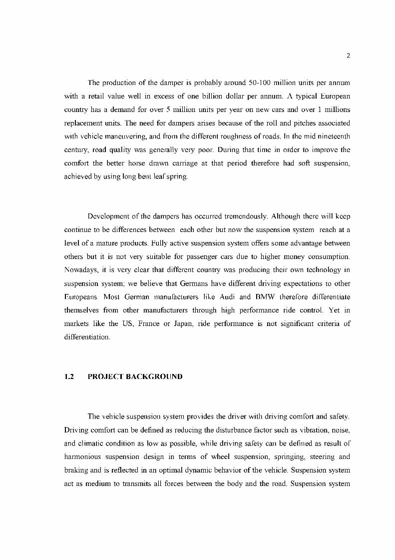
The production of the damper is probably around 50-100 million units per annum
with a retail value well in excess of one billion dollar per annum. A typical European
country has a demand for over 5 million units per year on new cars and over 1 millions
replacement units. The need for dampers arises because of the roll and pitches associated
with vehicle maneuvering, and from the different roughness of roads. In the mid nineteenth
century, road quality was generally very poor. During that time in order to improve the
comfort the better horse drawn carriage at that period therefore had soft suspension,
achieved by using long bent leaf spring.
Development of the dampers has occurred tremendously. Although there will keep
continue to be differences between each other but now the suspension system reach at a
level of a mature products. Fully active suspension system offers some advantage between
others but it is not very suitable for passenger cars due to higher money consumption.
Nowadays, it is very clear that different country was producing their own technology in
suspension system; we believe that Germans have different driving expectations to other
Europeans. Most German manufacturers like Audi and BMW therefore differentiate
themselves from other manufacturers through high performance ride control. Yet m
markets like the US, France or Japan, ride performance is not significant criteria of
differentiation.
1.2 PROJECT BACKGROUND
The vehicle suspension system provides the driver with driving comfort and safety.
Driving comfort can be defined as reducing the disturbance factor such as vibration, noise,
and climatic condition as low as possible, while driving safety can be defined as result of
harmonious suspension design in terms of wheel suspension, springing, steering and
braking and is reflected in an optimal dynamic behavior of the vehicle. Suspension system
act as medium to transmits all forces between the body and the road. Suspension system
3
can be divided into three main parts which are spring, damper and wishbones. For this
project it will focus on damper system only. Damper function is to slow down the
oscillations of body and wheel, this oscillation is produce from the dissipation of energy by
the spring. For the good damper it must contain the criteria where it can split between the
body and the wheel also called as sprung mass when the absorber experience factor that can
give effect to the absorber such as road disturbances. In this modem technology there are
three types of vehicle suspension system used which are passive, semi active and active. All
system normally used hydraulic or pneumatic operation but recently a new system was
found which used electromagnetic in suspension system.
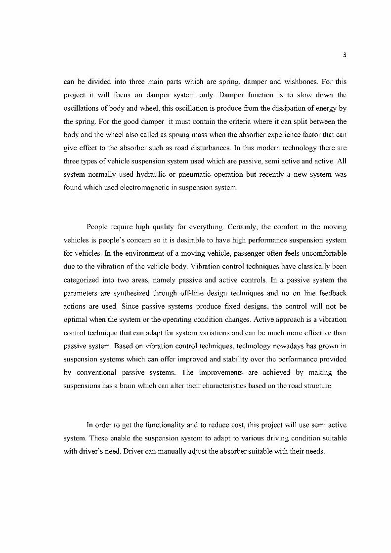
People require high quality for everything. Certainly, the comfort in the moving
vehicles is people's concern so it is desirable to have high performance suspension system
for vehicles. In the environment of a moving vehicle, passenger often feels uncomfortable
due to the vibration of the vehicle body. Vibration control techniques have classically been
categorized into two areas, namely passive and active controls. In a passive system the
parameters are synthesized through off-line design techniques and no on line feedback
actions are used. Since passive systems produce fixed designs, the control will not be
optimal when the system or the operating condition changes. Active approach is a vibration
control technique that can adapt for system variations and can be much more effective than
passive system. Based on vibration control techniques, technology nowadays has grown in
suspension systems which can offer improved and stability over the performance provided
by conventional passive systems. The improvements are achieved by making the
suspensions has a brain which can alter their characteristics based on the road structure.
In order to get the functionality and to reduce cost, this project will use semi active
system. These enable the suspension system to adapt to various driving condition suitable
with driver's need. Driver can manually adjust the absorber suitable with their needs.
4
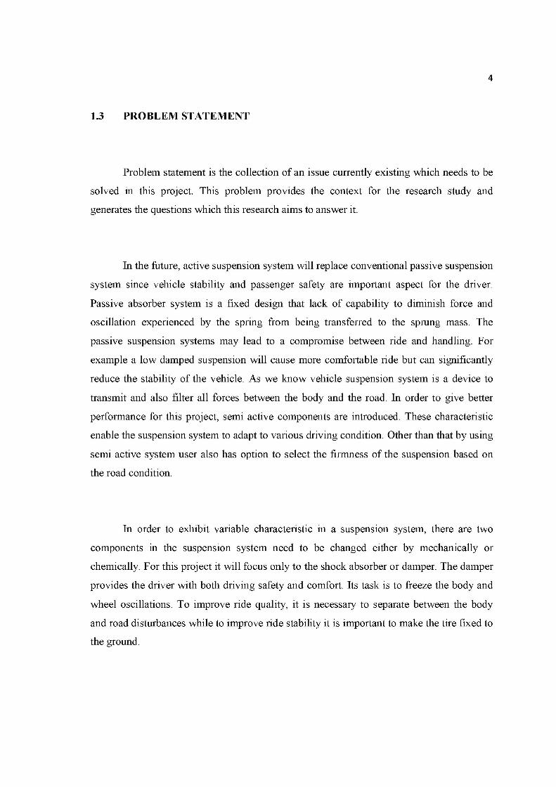
1.3 PROBLEM STATEMENT
Problem statement is the collection of an issue currently existing which needs to be
solved in this project. This problem provides the context for the research study and
generates the questions which this research aims to answer it.
In the future, active suspension system will replace conventional passive suspension
system since vehicle stability and passenger safety are important aspect for the driver.
Passive absorber system is a fixed design that lack of capability to diminish force and
oscillation experienced by the spring from being transferred to the sprung mass. The
passive suspension systems may lead to a compromise between ride and handling. For
example a low damped suspension will cause more comfortable ride but can significantly
reduce the stability of the vehicle. As we know vehicle suspension system is a device to
transmit and also filter all forces between the body and the road. In order to give better
performance for this project, semi active components are introduced. These characteristic
enable the suspension system to adapt to various driving condition. Other than that by using
semi active system user also has option to select the firmness of the suspension based on
the road condition.
In order to exhibit variable characteristic in a suspensiOn system, there are two
components in the suspension system need to be changed either by mechanically or
chemically. For this project it will focus only to the shock absorber or damper. The damper
provides the driver with both driving safety and comfort. Its task is to freeze the body and
wheel oscillations. To improve ride quality, it is necessary to separate between the body
and road disturbances while to improve ride stability it is important to make the tire fixed to
the ground.
5
Specific vehicle models need to be used in order to analyze the effectiveness of the
suspension system on vehicle dynamics, for this project it will use Proton Wira car as a
reference. A full vehicle model needs to present the nonlinear kinematics of wheels and
axles, the effect of suspension geometry and has to include the drive train the steering
mechanism and the tire dynamics resulting in a high number of degrees of freedom. The
full vehicle suspension system is represented as a linear seven degree of freedom (DOF)
system. It consists of a single sprung mass (car body) connected to four unsprung masses
(front-left, front right, rear left and rear right wheel) at each corner. The sprung mass is free
to bounce, pitch and roll while the unsprung masses are free only to bounce vertically with
respect to the sprung mass. The full vehicle suspension model is represented as a linear
seven degree of freedom system. Full vehicle suspension system consists of a single sprung
mass (car body) connected to four unsprung masses ml, m2, m3, and m4 (front left, front
right, rear left, rear right wheels) at each corner. The suspensions between the sprung mass
and unsprung masses are modeled as linear viscous dampers and spring elements while
tires are modeled as simple linear springs without damping components. For this project, in
order to achieve accuracy we will focus on physical models of suspension system in quarter
car model to be exact only to the rear tire. This aims to describe correctly the roll and pitch
motion of the car and the connected inertia forces.
Suspension system is closely related to four main problems which are comfort,
safety, energy and lastly maintenance. In this project we are choosing to look through in
comfort problem. Driving comfort can be defined as minimization the unnecessary factor
such as vibration, noise and climatic conditions down as low as possible to the vehicle.
There are two key factors that will look through in this comfort condition which are motion
and vibration. The acceleration of the body is an obvious quantity for motion and vibration
of the car body can be used for determining a quantitive value for driving comfort. There
are several factors that can affect the comfortness which are drop test, ride motions,
longitudinal acceleration transients and lastly lateral acceleration transients. In this project
it will more specified on the ride motions. A Ride motion is depend on the road roughness.
This project will focus on the movements of the vehicle in different road roughness.
6
Different road roughnesses have different displacement amplitude. Displacement amplitude
is a measurement of distance of the movement of a particle from its equilibrium position.
As the conclusion, our research problem is to modeling and simulation of semi
active suspension system which is damper for a rear tire to solve comfort problem when
experience different road condition.
1.4 PROJECT OBJECTIVES
Research objective set the purpose and focus the research on what we are going to
achieve by this project. It is similarly to the purpose or aim for the project. These are the
objectives that must be achieved from this research, there are:
(i) Modeling passive and semi active suspension system using MATLAB.
(ii) To identify the factor that makes the suspension systems become variable.
(iii)To design (CATIA) and fabricate semi active suspension system.
(iv)To distinguish the performance between passive and semi active suspension
system.
1.5 PROJECT SCOPES
Project scope will identify and minimize the scope of the project. So that, it will
make the project become more focus. In this project scope, it will clearly clarify condition
where it is included and excluded from this project. The scope of this project covers several
issues such as:
7
(i) This project valid only to the condition where ride motions are different in
response to road roughness other condition is ignored.
(ii) This project only acceptable to normal passenger car which is Proton Wira
suspension system, other brand of car will not be taken into account.
(iii)The scope of this project only valid to the rear wheel position.
1.6 REPORT ORGANIZATION
This report contains six sections which briefly describes the detailed information
about the research. All chapters are preceded by a brief synopsis of the chapter and key
words.
I (i) Introduction
This is the beginning section which states the purpose and goals of the thesis. In
this chapter, briefly describes the information in term of background, problem
statement, objectives, scopes and others. This chapter is important because it is
used to give general idea about this project.
(i) Literature review
In this chapter, published information in a particular subject area will be
discussed. Literature review provides background for your topic using previous
research.
(ii) Methodology
This chapter discussed about the procedures used in making experiments or
projects. It will mention the research platform setup, the steps taken to conduct
either simulation or experiment.
8
(iii)Result and discussion
Result obtains from experiment are shown in this chapter. The results are shown
in terms of graphs, figures and tables. Then, the results will be analyzed and
compared with the purpose of the simulations or experiments.
(iv)Conclusions and recommendations
This chapter summarized the overall of this project and to determine that the
results verify the hypothesis or not. Recommendations for future study and the
improvement in this field also stated in this chapter.
(v) References
In this chapter citation of a text that has been used in the creation of the thesis
was stated.
9
CHAPTER2
LITERATURE REVIEW
This chapter briefly describes the review on existing technology used in shock
absorber. This chapter comprises two sections: The first section describes the
comprehensive review on existing related technology. The second section describes the
review on method, equipment, and technology previously used in the same area.
2.1 HISTORY OF SHOCK ABSORBER
The first production of shock absorber is hard to be identified when it was begin.
But the production of the shock absorber arises rapidly by following the evolution of the
motor car itself The evolution of the shock absorber technology can be arranged in such
ways, based on its history: dry friction (snubbers) (figure 2.1 ), blow-off hydraulics,
progressive hydraulics, adjustable (manual alteration), slow adaptive (automatic alteration),
fast adaptive (semi active) and lastly followed by electro fluidic (magneto rheological) [1].
In 1913, the first car that used shock absorber is Silver Ghost the company called Rolls
Royce used discontinued rear dampers on the Silver Ghost [1]. From 1910 to 1925 mostly
10
all the motor car used dry snubbers technology [1]. From 1985, the evolution of shock
absorber become more widely increase on this period of time the technology was changed
from passive to active suspension by fast auto adjusting dampers [1]. In this millennium
era, from about 2000 the introduction of magnetorheological technology was founded, but
at this time this technology only exists on high price vehicles only [ 1]
Figure 2.1: The Andre-Hartford scissor-action dry friction damper.
2.2 INTRODUCTION
The comfort and safety aspect for the driver depends on the suspension system of
the vehicle as the suspension system carries the vehicle body and transmits all forces
between body and road [2].The vehicle suspension systems basically consists of wishbones,
the spring and the shock absorber to transmit and also filter all forces between body and
road [3]. The spring function is to carry the body mass and to isolate the body from road
disturbances and thus contributes to drive comfort while damper contributes to both driving
safety and comfort [3]. The damper function is to slow down the movement of body and
11
wheel oscillations; it directly refers to drive safety as a non-bouncing wheel is the condition
for transferring road-contact forces [3].
Nowadays, people require high quality for everything. In the contact of vehicles,
two factors that always take into consideration are driving safety and comfort. Driving
safety is the result of a harmonious suspension design in terms of wheel suspensions,
steering and braking and it is reflected in an optimal dynamic behavior of the vehicle [3].
Tire load variation is an indicator for the road contact and can be used to determining a
measurable value for safety [5]. While driving comfort is a results from keeping the
unnecessary condition that the vehicle experience such as vibrations, noise, and climatic
control [3]. For driving comfort condition, two factors that can give measureable value for
driving comfort are motion and vibration of the car body due to acceleration of the body
[5]. In the condition of a moving vehicle, passengers often feel uncomfortable due to the
vibration of the vehicle body [ 4 ].In order to solve this problem, effective vibration control
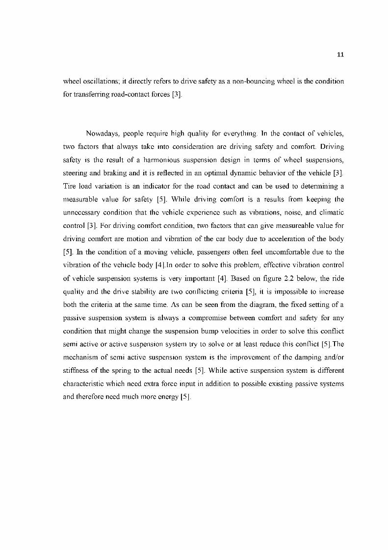
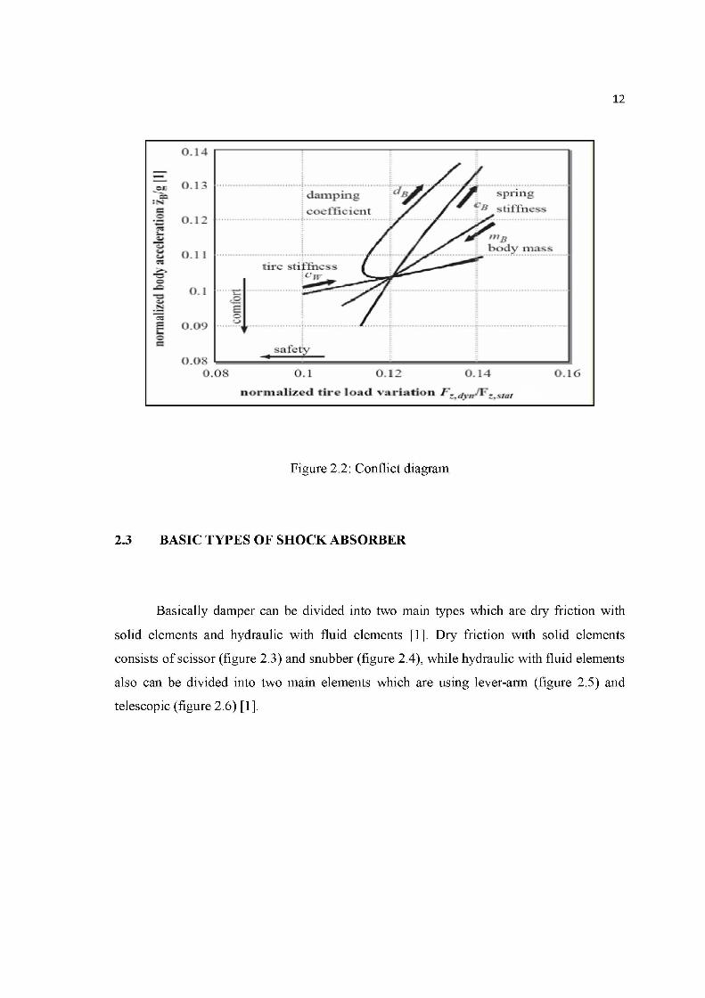
of vehicle suspension systems is very important [4]. Based on figure 2.2 below, the ride
quality and the drive stability are two conflicting criteria [5], it is impossible to increase
both the criteria at the same time. As can be seen from the diagram, the fixed setting of a
passive suspension system is always a compromise between comfort and safety for any
condition that might change the suspension bump velocities in order to solve this conflict
semi active or active suspension system try to solve or at least reduce this conflict [ 5]. The
mechanism of semi active suspension system is the improvement of the damping and/or
stiffness of the spring to the actual needs [5]. While active suspension system is different
characteristic which need extra force input in addition to possible existing passive systems
and therefore need much more energy [5].
12
0 . 1
e.t 0 . 13 -" s::: spn n g
= . lliTn . e O. l2 ·= ~ ... ~
~ .... 0 . 1 1 u <:0:1 >. -c 0
..Q .1 -= u :::: ""' E 0 .09 :c-
tire stiffnes _
1 ~ '
"' ""'i::: ~ E ! . 0 ' : -
--~ --~---- ..... • ... . :. ----~ ----------· ··- •. · --- ... : .. ~----- ---· . ---- · .. ---- ____ i_ _____ --- ... . ---~ ..... ............ .
e = safety o.os '-==,;;;:=;;;;;;;;;;;;;;;~==,;.,====~====='J
0.0 0.! O.L 0 .14 0. 6
Figure 2.2: Conflict diagram
2.3 BASIC TYPES OF SHOCK ABSORBER
Basically damper can be divided into two main types which are dry friction with
solid elements and hydraulic with fluid elements [1]. Dry friction with solid elements
consists of scissor (figure 2.3) and snubber (figure 2.4), while hydraulic with fluid elements
also can be divided into two main elements which are using lever-arm (figure 2.5) and
telescopic (figure 2.6) [1].