aircond report
TRANSCRIPT
8/8/2019 Aircond Report
http://slidepdf.com/reader/full/aircond-report 1/43
Final Summary Report by Air Conditioner Evaluation Standard
Subcommittee, Energy Efficiency Standards Subcommittee of the
Advisory Committee for Natural Resources and Energy
8/8/2019 Aircond Report
http://slidepdf.com/reader/full/aircond-report 2/43
1
The Air Conditioner Evaluation Standards Subcommittee conducted deliberations on judgment
standards for the manufacturers or importers (hereinafter referred to as “manufacturers”) concerning
performance improvement of air conditioners, and prepared a final summary report as below.
1. Evaluation of Current Standards
The weighted harmonic mean of energy consumption efficiency by the volume of shipments
of air conditioners (limited to those of wall-hung type among non-ducted types whose cooling
capacity is 4.0 kW or lower out of air conditioners used for both cooling and heating) whose the
target fiscal year finished in the 2004 freezing year was 5.05 (for products shipped in the 2004
freezing year). It corresponds to improvement by 67.8%, when compared with the weighted
harmonic mean of the energy consumption efficiency by shipments prior to introduction of the Top
Runner Standard (i.e., products shipped in the 1997 freezing year), which was 3.01. This meansthat improvements surpassing the energy consumption efficiency (5.00) and the assumed
improvement rate (66.1%), which was then assumed in case that Top Runner standards were
achieved.
In view of the above, energy-saving efforts in air conditioners (limited to those of wall-hung
type among non-ducted types whose cooling capacity is 4.0 kW or lower out of air conditioners
used for both cooling and heating) have been progressing well as a result of efforts by the
manufacturers for energy conservation, and thus we can evaluate that the current standards based
on the Top Runner Program are functioning effectively.
2. Target Scope [See Attachment 1]
This review shall cover air conditioners for household use (limited to those of wall-hung
type among non-ducted types whose cooling capacity is 4.0 kW or lower, out of air conditioners
used for both cooling and heating) whose the target year finished in the 2004 freezing year.
Air conditioners that use any energy other than electricity as a heat source for heating, highly
gas-tight/heat-insulating housing duct air-conditioning systems, and multi-functional heat pump
system air conditioners shall be excluded.
3. Items to be judgment standards for manufacturers
(1) Target fiscal year [See Attachment 2]
It shall be the fiscal year 2010.
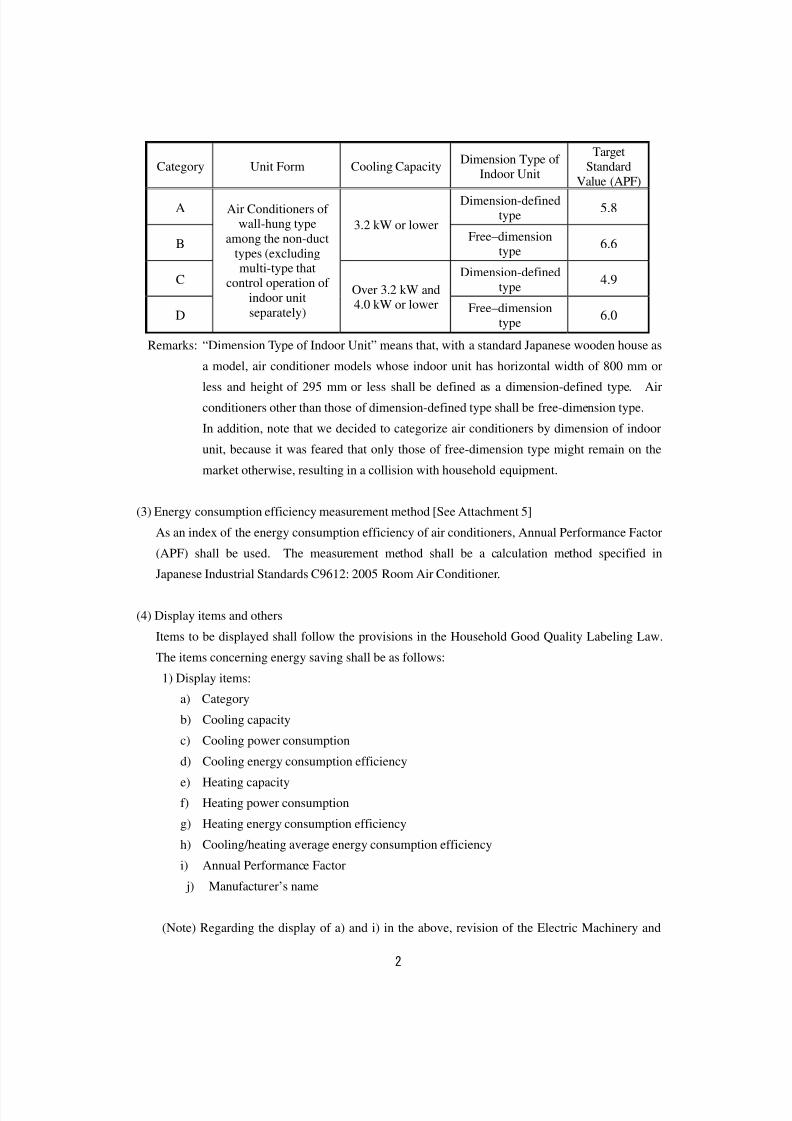
(2) Target standard values [See Attachments 3 to 4]
With regard to air conditioners that manufacturers ship within Japan for the target fiscal year, the
weighted harmonic mean of the energy consumption efficiency (Annual Performance Factor
(APF)) calculated in (3) by the volume of shipments for each manufacturer per category shown in
the table below shall not exceed the target standard value.
8/8/2019 Aircond Report
http://slidepdf.com/reader/full/aircond-report 3/43
2
Category Unit Form Cooling CapacityDimension Type of
Indoor Unit
TargetStandard
Value (APF)
ADimension-defined
type 5.8
B
3.2 kW or lower Free–dimension
type 6.6
CDimension-defined
type 4.9
D
Air Conditioners of wall-hung type
among the non-duct
types (excludingmulti-type that
control operation of
indoor unit
separately)
Over 3.2 kW and4.0 kW or lower Free–dimension
type 6.0
Remarks: “Dimension Type of Indoor Unit” means that, with a standard Japanese wooden house as
a model, air conditioner models whose indoor unit has horizontal width of 800 mm or
less and height of 295 mm or less shall be defined as a dimension-defined type. Air
conditioners other than those of dimension-defined type shall be free-dimension type.
In addition, note that we decided to categorize air conditioners by dimension of indoor
unit, because it was feared that only those of free-dimension type might remain on the
market otherwise, resulting in a collision with household equipment.
(3) Energy consumption efficiency measurement method [See Attachment 5]
As an index of the energy consumption efficiency of air conditioners, Annual Performance Factor
(APF) shall be used. The measurement method shall be a calculation method specified in
Japanese Industrial Standards C9612: 2005 Room Air Conditioner.
(4) Display items and others
Items to be displayed shall follow the provisions in the Household Good Quality Labeling Law.
The items concerning energy saving shall be as follows:
1) Display items:
a) Category
b) Cooling capacity
c) Cooling power consumption
d) Cooling energy consumption efficiency
e) Heating capacity
f) Heating power consumption
g) Heating energy consumption efficiency
h) Cooling/heating average energy consumption efficiency
i) Annual Performance Factor
j) Manufacturer’s name
(Note) Regarding the display of a) and i) in the above, revision of the Electric Machinery and
8/8/2019 Aircond Report
http://slidepdf.com/reader/full/aircond-report 4/43
3
Appliance Quality Labeling Regulations is required.
2) Compliance items
a) The cooling capacity shall be displayed in kilowatts measured by the method specified
in the cooling capacity test in Japanese Industrial Standards B8615-1. In this case, the
allowable range shall be up to minus 5% of the displayed value.
b) The heating capacity shall be displayed in kilowatts measured by the method specified
in the heating capacity test in Japanese Industrial Standard B8615-1. In this case, the
allowable range shall be up to minus 5% of the displayed value.
c) The cooling power consumption shall be in watts or kilowatts measured by the method
specified in the cooling power consumption test in Japanese Industrial Standard B8615-1.
In this case, the allowable range shall be up to plus 10% of the displayed value.d) The heating power consumption shall be in watts or kilowatts measured by the method
specified in the heating power consumption test in Japanese Industrial Standard B8615-1.
In this case, the allowable range shall be up to plus 10% of the displayed value.
e) The cooling energy consumption efficiency or heating energy consumption efficiency
shall be a numeric value obtained by dividing the cooling capacity in kilowatts measured
by the method specified in a) above by the cooling power consumption in kilowatts
measured by the method specified in c) above. The obtained value shall be displayed
to two places of decimals.
f) The heating energy consumption efficiency shall be a numeric value obtained by
dividing the heating capacity in kilowatts measured by the method specified in b) above
by the heating power consumption in kilowatts measured by the method specified in d)
above. The obtained value shall be displayed to two places of decimals.
g) The cooling/heating average energy consumption shall be obtained by summing the
cooling energy consumption efficiency and the heating energy consumption efficiency
and then dividing it by 2. The obtained value shall be displayed to two places of
decimals.
h) Annual Performance Factor shall be obtained by dividing the sum of heat quantity to be
removed from indoor air and that to be added to indoor air throughout cooling period
and heating period by total energy consumption to be consumed during the same period;
these heat quantities are obtained by the test and calculating method for seasonal energy
efficiency specified in Japanese Industrial Standards C9612: 2005. The obtained APF
shall be displayed to one place of decimal.
i) Should any difference arise in measurements specified in a) to h) above due to different
rated frequencies, measured values would be displayed for every rated frequency.
j) The display items listed in 1) above shall be clearly placed on prominent positions in
catalogues or instruction manuals so that consumers can refer to them when selecting
equipment.
8/8/2019 Aircond Report
http://slidepdf.com/reader/full/aircond-report 5/43
4
4. Proposals for energy saving
(1) Actions of users
1) Through effective use of information such as “energy-saving labels”, etc, users are
encouraged to make an attempt to not only select an air conditioner with excellent energy
consumption efficiency but also reduce energy by using it appropriately and efficiently.
2) Users shall attempt to select an air conditioner while considering the setting or size of a room
to install it in, in order to make full use of its capacity.
(2) Actions of retailers
1) Retailers shall attempt to not only distribute air conditioners with excellent energy
consumption efficiency but also provide appropriate information for users to select them
through use of “energy-saving labels”, etc. When using the energy-saving labels, as air
conditioners vary in performance depending on areas where to be used, retailers shall
carefully display labels in a manner that users can easily understand and get no false
impression by means of, for example, showing conditions for calculating energy consumption
efficiency.
(3) Actions of manufacturers
1) Manufactures shall promote technological development toward energy saving of air
conditioners and attempt to develop products with excellent energy consumption efficiency.
2) From viewpoint of promoting the spread of air conditioners with excellent energy
consumption efficiency, manufacturers shall attempt to provide appropriate information to
encourage users to select air conditioners with excellent energy consumption efficiency, by
displaying “energy-saving labels” in a catalogue, etc. As air conditioners vary in
performance depending on areas where to be used, in implementing the energy-saving labels,
manufacturers shall carefully display them in a manner that users can easily understand and
get no false impression, by means of, for example, showing conditions for calculating energy
consumption efficiency.
3) To respond to improved energy-saving performances such as insulation performance of
buildings, etc. in recent years, manufacturers shall review guideline for applicable room sizes
according to cooling capacity and heating capacity.
4) Since Annual Performance Factor (APF) adopted in this report is based on numeric values
computed under certain conditions, manufacturers shall attempt to improve the measurement
8/8/2019 Aircond Report
http://slidepdf.com/reader/full/aircond-report 6/43
5
method in the future as well, so that evaluation can be carried out in a condition closer to
actual use.
(4) Actions of Government
1) From viewpoint of promoting the spread of air conditioners with excellent energy
consumption efficiency, the government shall attempt to take necessary action such as the
spread and enlightenment activities, in order to promote actions of users and manufacturers.
2) The government shall periodically and continuously monitor the implementation status of the
display items by manufacturers and attempt at appropriate operation of the law so that
information on energy consumption efficiency can be provided to users in a correct and easily
understandable manner.3) The energy-saving standard based on the Top Runner Program is a very effective approach for
energy saving of products. Therefore, the government shall make efforts to spread it
internationally by catching appropriate opportunities.
8/8/2019 Aircond Report
http://slidepdf.com/reader/full/aircond-report 7/43
6
Attachment 1
Target Scope
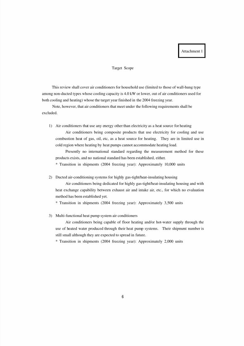
This review shall cover air conditioners for household use (limited to those of wall-hung type
among non-ducted types whose cooling capacity is 4.0 kW or lower, out of air conditioners used for
both cooling and heating) whose the target year finished in the 2004 freezing year.
Note, however, that air conditioners that meet under the following requirements shall be
excluded.
1) Air conditioners that use any energy other than electricity as a heat source for heating
Air conditioners being composite products that use electricity for cooling and use
combustion heat of gas, oil, etc, as a heat source for heating. They are in limited use in
cold region where heating by heat pumps cannot accommodate heating load.
Presently no international standard regarding the measurement method for these
products exists, and no national standard has been established, either.
* Transition in shipments (2004 freezing year): Approximately 10,000 units
2) Ducted air-conditioning systems for highly gas-tight/heat-insulating housing
Air conditioners being dedicated for highly gas-tight/heat-insulating housing and with
heat exchange capability between exhaust air and intake air, etc., for which no evaluation
method has been established yet.
* Transition in shipments (2004 freezing year): Approximately 3,500 units
3) Multi-functional heat pump system air conditioners
Air conditioners being capable of floor heating and/or hot-water supply through the
use of heated water produced through their heat pump systems. Their shipment number is
still small although they are expected to spread in future.
* Transition in shipments (2004 freezing year): Approximately 2,000 units
8/8/2019 Aircond Report
http://slidepdf.com/reader/full/aircond-report 8/43
7
Attachment 2
Target Year, etc, of Air Conditioners
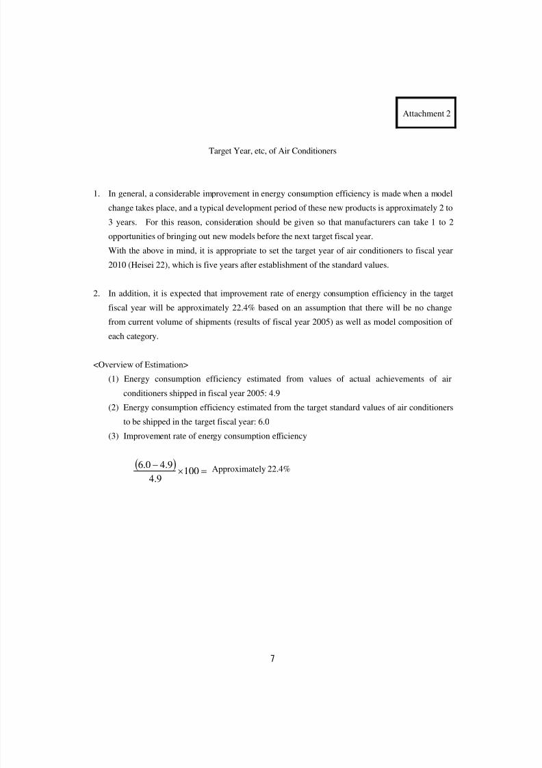
1. In general, a considerable improvement in energy consumption efficiency is made when a model
change takes place, and a typical development period of these new products is approximately 2 to
3 years. For this reason, consideration should be given so that manufacturers can take 1 to 2
opportunities of bringing out new models before the next target fiscal year.
With the above in mind, it is appropriate to set the target year of air conditioners to fiscal year
2010 (Heisei 22), which is five years after establishment of the standard values.
2. In addition, it is expected that improvement rate of energy consumption efficiency in the target
fiscal year will be approximately 22.4% based on an assumption that there will be no change
from current volume of shipments (results of fiscal year 2005) as well as model composition of
each category.
<Overview of Estimation>
(1) Energy consumption efficiency estimated from values of actual achievements of air
conditioners shipped in fiscal year 2005: 4.9
(2) Energy consumption efficiency estimated from the target standard values of air conditioners
to be shipped in the target fiscal year: 6.0
(3) Improvement rate of energy consumption efficiency
( )=×
−
1009.4
9.40.6 Approximately 22.4%
8/8/2019 Aircond Report
http://slidepdf.com/reader/full/aircond-report 9/43
8
Attachment 3
Classification of Air Conditioners
1 Basic Idea
Idea of classification for overall air conditioners under the current standard is based on the
following:
1) Classification by basic function
2) Classification by unit form
3) Classification by cooling capacity
In the scope of this review, air conditioners are classified as shown below:
Unit Form Cooling Capacity
2.5 kW or lower
Over 2.5kW,
3.2 kW or lower
Air conditioners of wall-hung type
among the non-duct types
(excluding multi-type air
conditioners that control operation
of indoor unit separately)Over 3.2kW,
4.0 kW or lower
Table 1: Current classification in the scope of this review
Air conditioners shall be classified, taking into consideration the fact that heat exchangers
recently have been growing in size in order to improve energy-saving performance.
2. Specific Classification Method
(1) Classification by design concept accompanying increased size of heat exchangers
The growing size of heat exchangers shall be a major factor in improvement of energy
consumption efficiency. Thus, current products (products that have satisfied the current
standard) are roughly divided based on the design concept, as shown below:
1) Models that meet the current standard values in terms of energy saving while considering
installation space and/or resource saving as well
2) Models that pursue energy-saving performance with no limit being imposed in terms of
installation space and/or resource saving
If this classification was not made in this review, it was feared that only air conditioners
8/8/2019 Aircond Report
http://slidepdf.com/reader/full/aircond-report 10/43
9
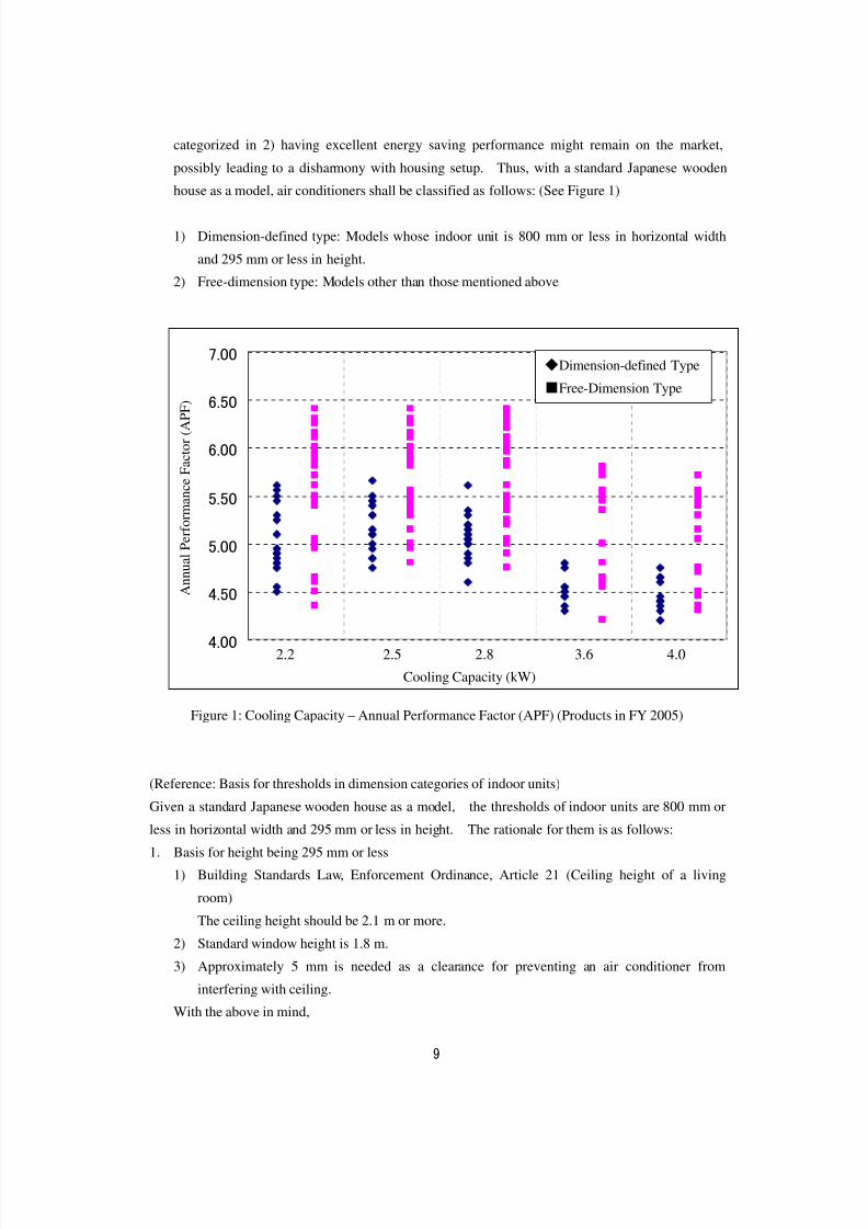
categorized in 2) having excellent energy saving performance might remain on the market,
possibly leading to a disharmony with housing setup. Thus, with a standard Japanese wooden
house as a model, air conditioners shall be classified as follows: (See Figure 1)
1) Dimension-defined type: Models whose indoor unit is 800 mm or less in horizontal width
and 295 mm or less in height.
2) Free-dimension type: Models other than those mentioned above
4.00
4.50
5.00
5.50
6.00
6.50
7.00
冷房能力(kW)
通 年 エ ネ ル ギ ー 消 費 効 率 ( A P F
)
Figure 1: Cooling Capacity – Annual Performance Factor (APF) (Products in FY 2005)
(Reference: Basis for thresholds in dimension categories of indoor units)
Given a standard Japanese wooden house as a model, the thresholds of indoor units are 800 mm or
less in horizontal width and 295 mm or less in height. The rationale for them is as follows:
1. Basis for height being 295 mm or less
1) Building Standards Law, Enforcement Ordinance, Article 21 (Ceiling height of a living
room)
The ceiling height should be 2.1 m or more.
2) Standard window height is 1.8 m.
3) Approximately 5 mm is needed as a clearance for preventing an air conditioner from
interfering with ceiling.
With the above in mind,
2.2 2.5 2.8 3.6 4.0
◆Dimension-defined Type
■Free-Dimension Type
A n n u a l P e r f o r m a n c e F a c t o r ( A P F )
Cooling Capacity (kW)
8/8/2019 Aircond Report
http://slidepdf.com/reader/full/aircond-report 11/43
10
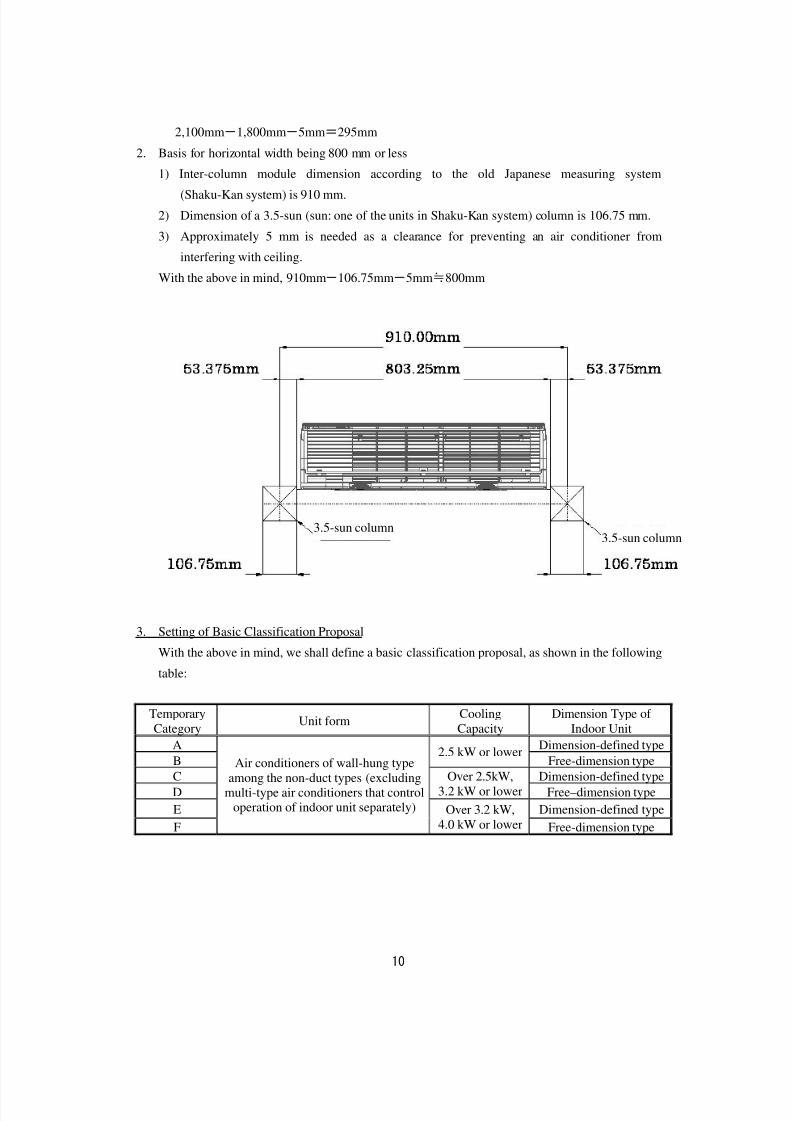
2,100mm-1,800mm-5mm=295mm
2. Basis for horizontal width being 800 mm or less
1) Inter-column module dimension according to the old Japanese measuring system
(Shaku-Kan system) is 910 mm.
2) Dimension of a 3.5-sun (sun: one of the units in Shaku-Kan system) column is 106.75 mm.
3) Approximately 5 mm is needed as a clearance for preventing an air conditioner from
interfering with ceiling.
With the above in mind, 910mm-106.75mm-5mm≒800mm
3. Setting of Basic Classification Proposal
With the above in mind, we shall define a basic classification proposal, as shown in the following
table:
Temporary
Category Unit form
Cooling
Capacity
Dimension Type of
Indoor UnitA Dimension-defined type
B2.5 kW or lower
Free-dimension type
C Dimension-defined type
D
Over 2.5kW,
3.2 kW or lower Free–dimension type
E Dimension-defined type
F
Air conditioners of wall-hung type
among the non-duct types (excludingmulti-type air conditioners that control
operation of indoor unit separately) Over 3.2 kW,
4.0 kW or lower Free-dimension type
3.5-sun column3.5-sun column
8/8/2019 Aircond Report
http://slidepdf.com/reader/full/aircond-report 12/43
11
Attachment 4
Target Standard Values of Air Conditioners
1. Idea on Establishment of Target Standard Values
(1) Basic idea
We shall set target standard values based on the idea of Top Runner Method. The specific
policy shall be as follows:
1) Target standard values shall be set for every category that has been defined appropriately.
2) As for categories where future technological advances are expected to improve efficiency,
the target standard value shall allow for as much improvement as possible.
3) Target standard values shall not conflict among categories.
(2) Target fiscal year
In general, a considerable improvement in energy consumption efficiency is made when a
model change takes place, and a typical development period of these new products is
approximately 2 to 3 years. For this reason, consideration should be given so that
manufacturers can take 1 to 2 opportunities of bringing out new models before the next target
fiscal year.
With the above in mind, it is appropriate to set the target year of air conditioners to fiscal year
2010 (Heisei 22), which is five years after establishment of the standards.
(3) Room for improvement of energy consumption efficiency by future technology advances
Technology development of air conditioners has been undertaken primarily for
establishment of a comfortable living environment. Although technology development related
to improvement of energy-saving performance has been implemented to accomplish the current
target standards, development of each elemental technology has almost reached its limit and thus
innovative technology development is hardly expected.
[Main examples of technologies for improving efficiency of air conditioners] (See reference 2)
・ Compressors: High-efficient compression technology, neodymium magnet, improvement of
motor winding, low-iron-loss magnetic steel sheet, reduction of mechanical loss,
reduction of pressure drop in suction/discharge, sine-wave drive control
8/8/2019 Aircond Report
http://slidepdf.com/reader/full/aircond-report 13/43
12
・ Fan motor: Introduction of DC brushless motor, increased number of poles/introduction of
slots, optimization of core shape, reduction of circuit loss, optimal energization
・ Electronically controlled valve
・ Heat exchanger: Three-row arrangement of an indoor unit, multi-stage bending, improvement
of fin shape, improvement of piping process
Although these technologies have been introduced into the current Top Runner equipment,
it can be said that there still remains room for efficiency improvement in individual technologies,
considering the fact that these introduced technologies differ depending on manufacturers and
that each manufacturer is taking its own approach for further improvement of efficiency.
Taking into consideration the fact in comprehensive manner that these factors might contribute to
higher efficiency, we set the target standard value by 3% up from the current Top Runner Valuefor the dimension-defined type and by 4% for the free dimension type.
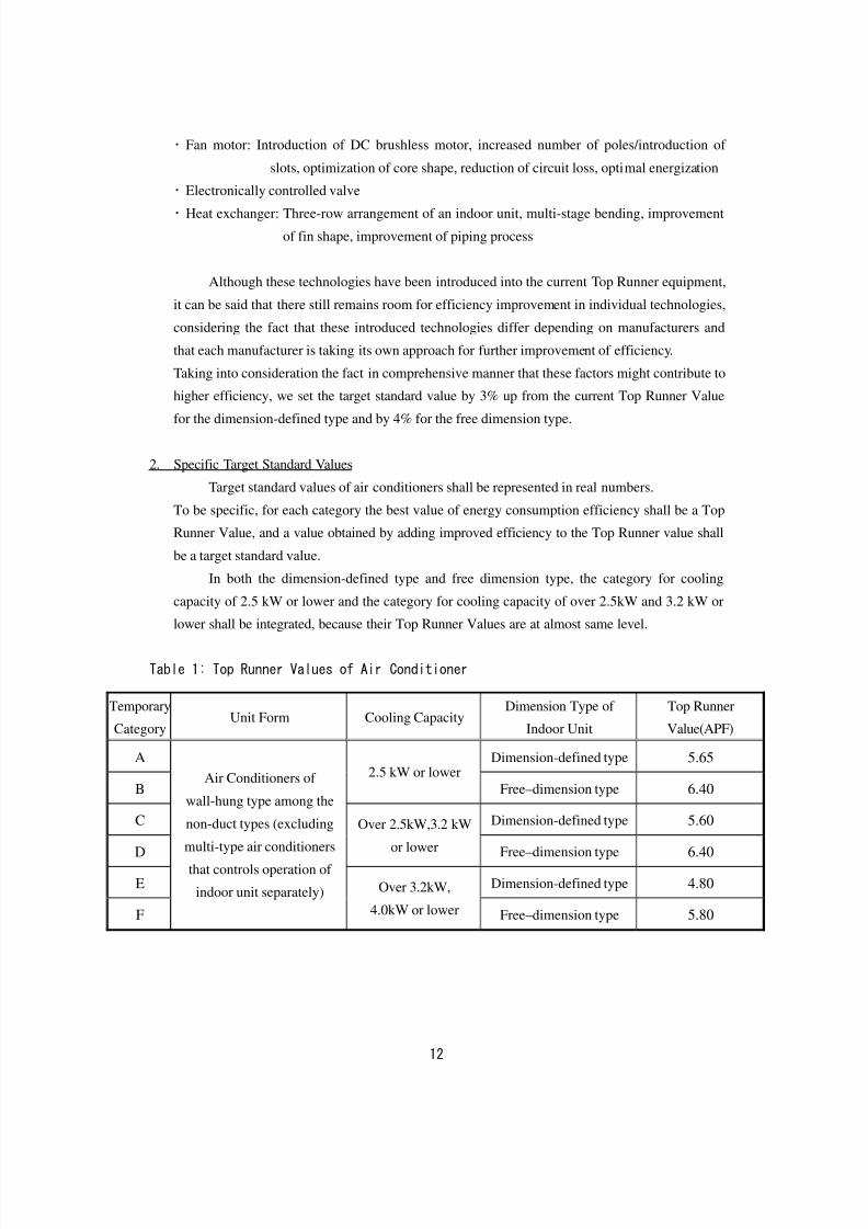
2. Specific Target Standard Values
Target standard values of air conditioners shall be represented in real numbers.
To be specific, for each category the best value of energy consumption efficiency shall be a Top
Runner Value, and a value obtained by adding improved efficiency to the Top Runner value shall
be a target standard value.
In both the dimension-defined type and free dimension type, the category for cooling
capacity of 2.5 kW or lower and the category for cooling capacity of over 2.5kW and 3.2 kW or
lower shall be integrated, because their Top Runner Values are at almost same level.
Table 1: Top Runner Values of Air Conditioner
Temporary
Category Unit Form Cooling Capacity
Dimension Type of
Indoor Unit
Top Runner
Value(APF)
A Dimension-defined type 5.65
B
2.5 kW or lower
Free–dimension type 6.40
C Dimension-defined type 5.60
D
Over 2.5kW,3.2 kW
or lower Free–dimension type 6.40
E Dimension-defined type 4.80
F
Air Conditioners of
wall-hung type among the
non-duct types (excluding
multi-type air conditioners
that controls operation of
indoor unit separately) Over 3.2kW,
4.0kW or lower Free–dimension type 5.80
8/8/2019 Aircond Report
http://slidepdf.com/reader/full/aircond-report 14/43
13
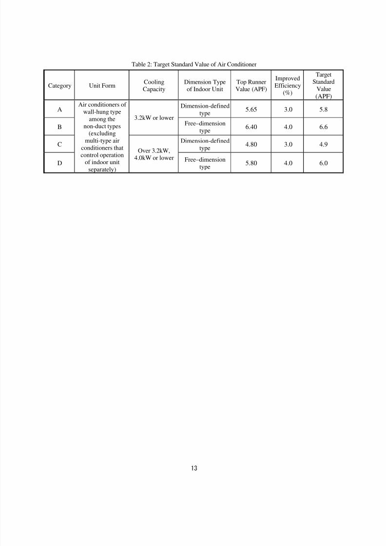
Table 2: Target Standard Value of Air Conditioner
Category Unit Form
Cooling
Capacity
Dimension Type
of Indoor Unit
Top Runner
Value (APF)
Improved
Efficiency(%)
TargetStandard
Value (APF)
ADimension-defined
type5.65 3.0 5.8
B
3.2kW or lowerFree–dimension
type 6.40 4.0 6.6
CDimension-defined
type4.80 3.0 4.9
D
Air conditioners of
wall-hung type
among thenon-duct types
(excluding
multi-type air
conditioners thatcontrol operation
of indoor unit
separately)
Over 3.2kW, 4.0kW or lower Free–dimension
type 5.80 4.0 6.0
8/8/2019 Aircond Report
http://slidepdf.com/reader/full/aircond-report 15/43
14
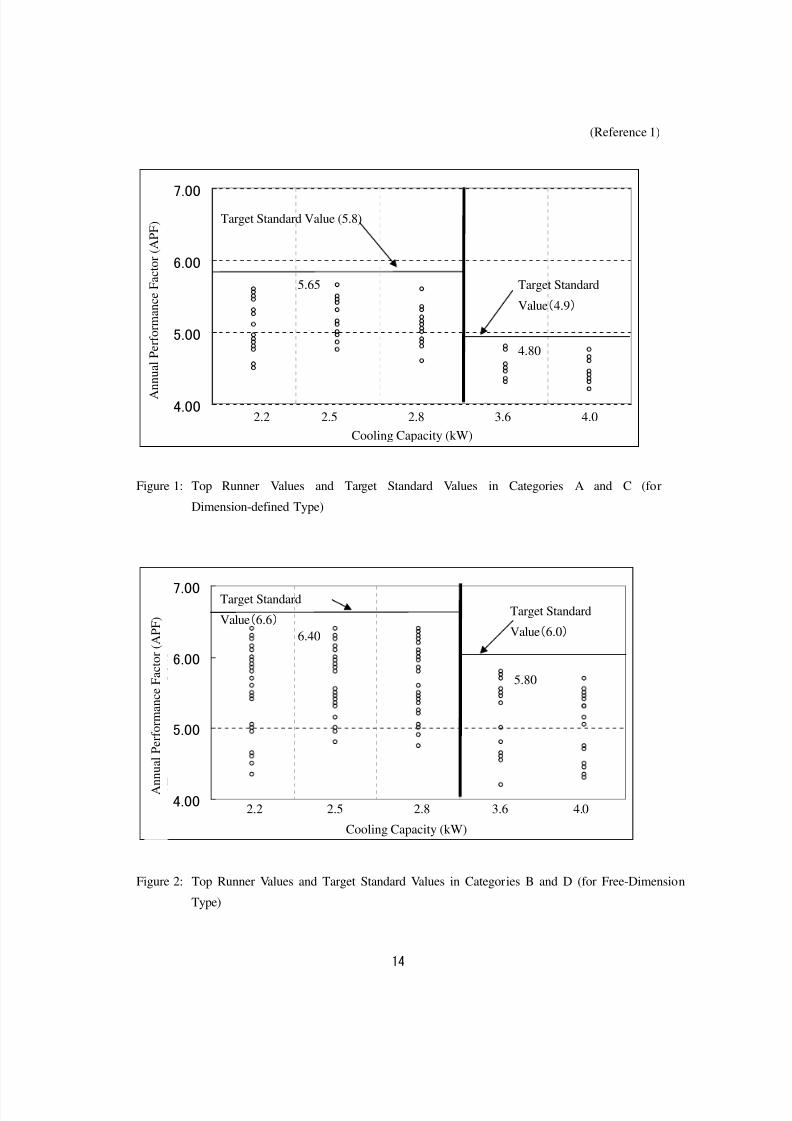
(Reference 1)
4.00
5.00
6.00
7.00
冷房能力(kW)
通 年 エ
ネ ル ギ ー 消 費 効 率 ( A P F )
Figure 1: Top Runner Values and Target Standard Values in Categories A and C (for
Dimension-defined Type)
4.00
5.00
6.00
7.00
冷房能力(kW)
通 年 エ ネ ル
ギ ー 消 費 効 率 ( A P F )
Figure 2: Top Runner Values and Target Standard Values in Categories B and D (for Free-Dimension
Type)
4.80
2.2 2.5 2.8 3.6 4.0
6.40
5.80
Target Standard
Value(6.0)
5.65
Target Standard Value (5.8)
Target Standard
Value(4.9)
Target Standard
Value(6.6)
2.2 2.5 2.8 3.6 4.0
A n n u a l
P e r f o r m a n c e F a c t o r ( A P F )
Cooling Capacity (kW)
A n n u a l P e r f o r m a n c e F a c t o r ( A P F )
Cooling Capacity (kW)
8/8/2019 Aircond Report
http://slidepdf.com/reader/full/aircond-report 16/43
15
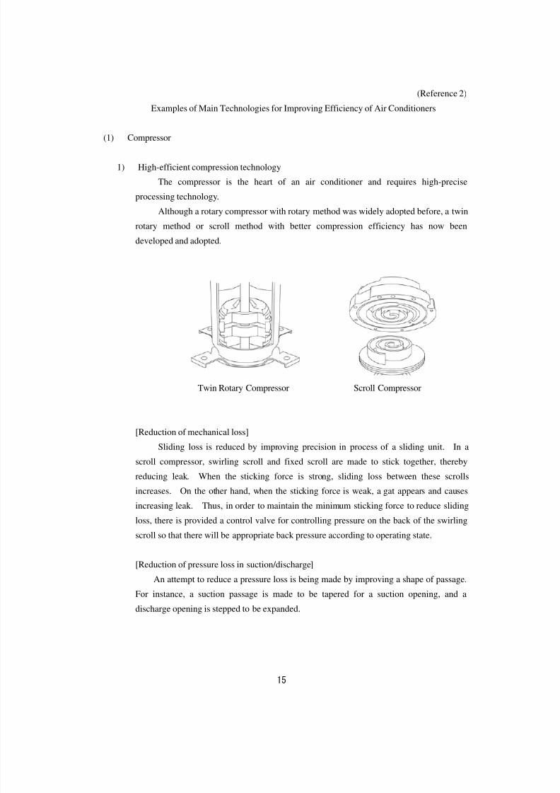
(Reference 2)
Examples of Main Technologies for Improving Efficiency of Air Conditioners
(1) Compressor
1) High-efficient compression technology
The compressor is the heart of an air conditioner and requires high-precise
processing technology.
Although a rotary compressor with rotary method was widely adopted before, a twin
rotary method or scroll method with better compression efficiency has now been
developed and adopted.
Twin Rotary Compressor Scroll Compressor
[Reduction of mechanical loss]
Sliding loss is reduced by improving precision in process of a sliding unit. In a
scroll compressor, swirling scroll and fixed scroll are made to stick together, thereby
reducing leak. When the sticking force is strong, sliding loss between these scrolls
increases. On the other hand, when the sticking force is weak, a gat appears and causes
increasing leak. Thus, in order to maintain the minimum sticking force to reduce sliding
loss, there is provided a control valve for controlling pressure on the back of the swirling
scroll so that there will be appropriate back pressure according to operating state.
[Reduction of pressure loss in suction/discharge]
An attempt to reduce a pressure loss is being made by improving a shape of passage.
For instance, a suction passage is made to be tapered for a suction opening, and a
discharge opening is stepped to be expanded.
8/8/2019 Aircond Report
http://slidepdf.com/reader/full/aircond-report 17/43
16
2) Compressor motor
[Neodymium magnet]
An attempt to improve motor efficiency is made by changing ferrite that has been
conventionally used in a rotor to neodymium that has high magnetic flux density.
[Improvement of line area ratio of winding]
A proportion of total coil sectional area within the stator to a stator slot area is
referred to a line-area ratio. If the line-area ratio could be increased, the coil sectional
area could be expanded, thereby reducing copper loss.
In the past, as coil was threaded through a narrow space within a closed stator and
winded, there remained a large dead space in the stator slot. However, development of a
new manufacturing method allows for the high line-area ratio by winding the coil to thestator divided and spread out.
In addition, coil covering an end face of a stator core can be reduced by directly
coiling the stator (intensive winding), thus also reducing copper loss.
[Low-iron-loss magnetic steel sheet]
One of the factors of iron loss is eddy-current loss caused by eddy current generated
in an iron core. Attempts have been made to prevent this current from flowing easily by
means of, for example, adoption of silicon steel plates and/or thin laminated steel sheets.
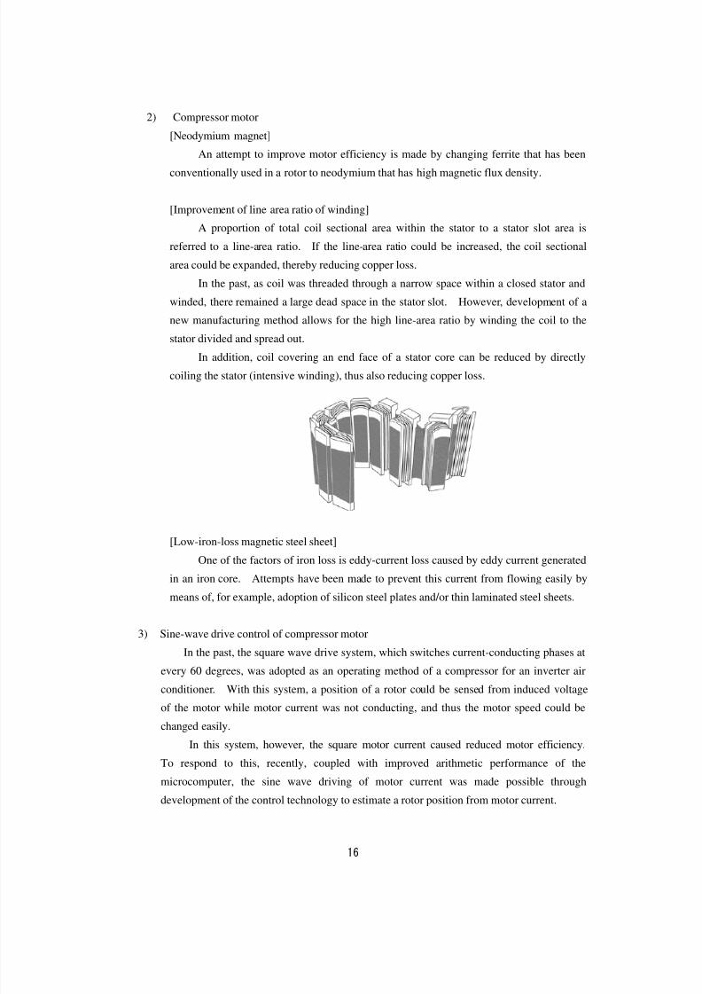
3) Sine-wave drive control of compressor motor
In the past, the square wave drive system, which switches current-conducting phases at
every 60 degrees, was adopted as an operating method of a compressor for an inverter air
conditioner. With this system, a position of a rotor could be sensed from induced voltage
of the motor while motor current was not conducting, and thus the motor speed could be
changed easily.
In this system, however, the square motor current caused reduced motor efficiency.
To respond to this, recently, coupled with improved arithmetic performance of the
microcomputer, the sine wave driving of motor current was made possible through
development of the control technology to estimate a rotor position from motor current.
8/8/2019 Aircond Report
http://slidepdf.com/reader/full/aircond-report 18/43
17
Waveform of Motor Current of Square-Wave
Driving System
Waveform of Motor Current of Sine-Wave
Driving System
(2) Blowers
1) Indoor blower
Various types of fans depending on unit form are used for blowers of indoor units. A“cross flow fan” is used for most of the wall-hung type air conditioners.
[Cross Flow Fan]
Although a cross flow fan was composed of blades that were processed metal sheets in
the past, an attempt to increase air volume has been made through introduction of plastic
blades having a wing-shaped section and growing size of fan diameter, while controlling
noise.
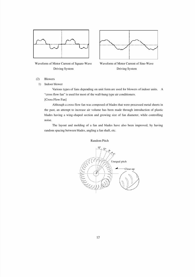
The layout and molding of a fan and blades have also been improved, by having
random spacing between blades, angling a fan shaft, etc.
Random Pitch
Unequal pitch
Close-up
8/8/2019 Aircond Report
http://slidepdf.com/reader/full/aircond-report 19/43
18
2) Outdoor blower
In general, a propeller fan is used for an outdoor unit of an air conditioner. Although
it was made of processed metal sheets in the past, it is now made of plastics. An attempt to
increase air volume has been made by improving a blade shape, while suppressing noise.
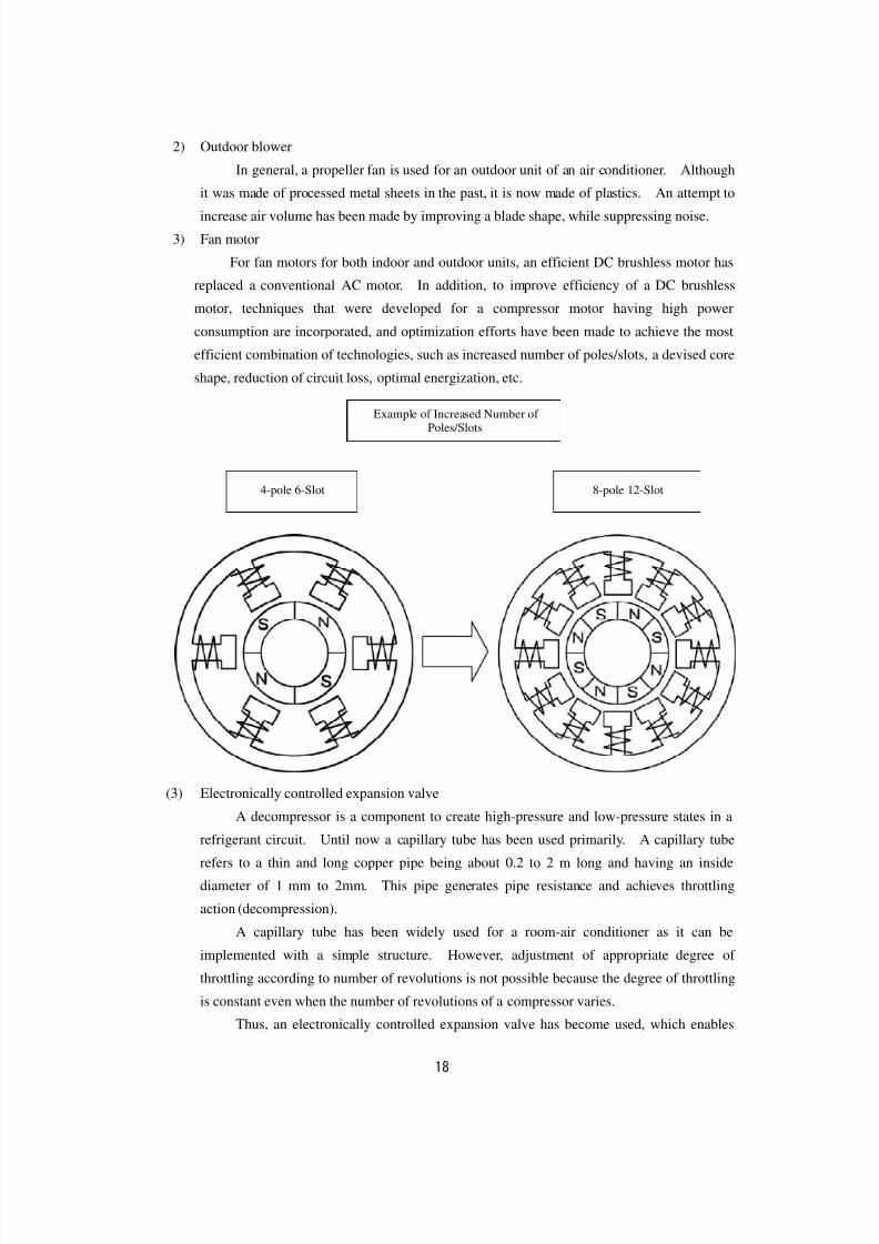
3) Fan motor
For fan motors for both indoor and outdoor units, an efficient DC brushless motor has
replaced a conventional AC motor. In addition, to improve efficiency of a DC brushless
motor, techniques that were developed for a compressor motor having high power
consumption are incorporated, and optimization efforts have been made to achieve the most
efficient combination of technologies, such as increased number of poles/slots, a devised core
shape, reduction of circuit loss, optimal energization, etc.
(3) Electronically controlled expansion valve
A decompressor is a component to create high-pressure and low-pressure states in a
refrigerant circuit. Until now a capillary tube has been used primarily. A capillary tube
refers to a thin and long copper pipe being about 0.2 to 2 m long and having an inside
diameter of 1 mm to 2mm. This pipe generates pipe resistance and achieves throttling
action (decompression).
A capillary tube has been widely used for a room-air conditioner as it can be
implemented with a simple structure. However, adjustment of appropriate degree of
throttling according to number of revolutions is not possible because the degree of throttling
is constant even when the number of revolutions of a compressor varies.
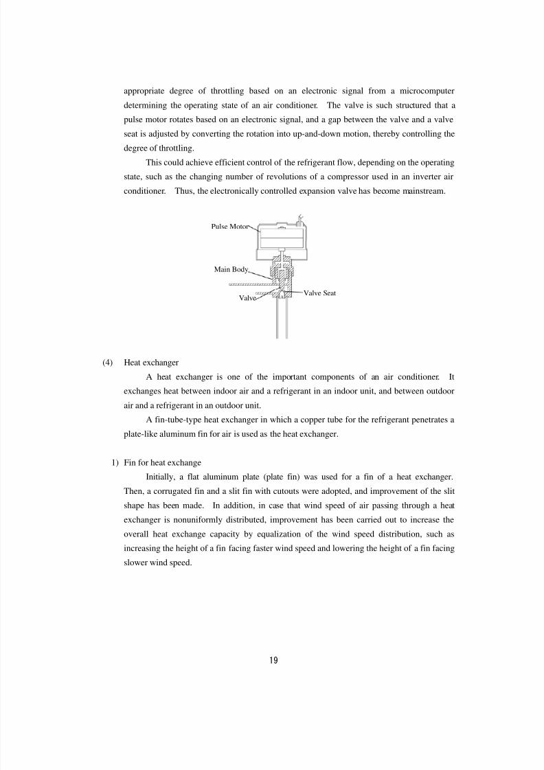
Thus, an electronically controlled expansion valve has become used, which enables
Example of Increased Number of Poles/Slots
4-pole 6-Slot 8-pole 12-Slot
8/8/2019 Aircond Report
http://slidepdf.com/reader/full/aircond-report 20/43
19
appropriate degree of throttling based on an electronic signal from a microcomputer
determining the operating state of an air conditioner. The valve is such structured that a
pulse motor rotates based on an electronic signal, and a gap between the valve and a valve
seat is adjusted by converting the rotation into up-and-down motion, thereby controlling the
degree of throttling.
This could achieve efficient control of the refrigerant flow, depending on the operating
state, such as the changing number of revolutions of a compressor used in an inverter air
conditioner. Thus, the electronically controlled expansion valve has become mainstream.
(4) Heat exchanger
A heat exchanger is one of the important components of an air conditioner. It
exchanges heat between indoor air and a refrigerant in an indoor unit, and between outdoor
air and a refrigerant in an outdoor unit.
A fin-tube-type heat exchanger in which a copper tube for the refrigerant penetrates a
plate-like aluminum fin for air is used as the heat exchanger.
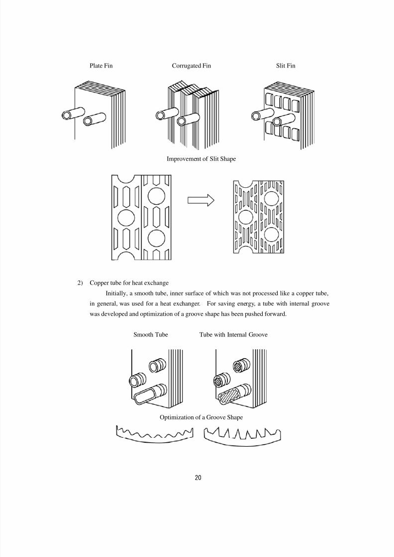
1) Fin for heat exchange
Initially, a flat aluminum plate (plate fin) was used for a fin of a heat exchanger.
Then, a corrugated fin and a slit fin with cutouts were adopted, and improvement of the slit
shape has been made. In addition, in case that wind speed of air passing through a heat
exchanger is nonuniformly distributed, improvement has been carried out to increase the
overall heat exchange capacity by equalization of the wind speed distribution, such as
increasing the height of a fin facing faster wind speed and lowering the height of a fin facing
slower wind speed.
Valve SeatValve
Main Body
Pulse Motor
8/8/2019 Aircond Report
http://slidepdf.com/reader/full/aircond-report 21/43
20
Plate Fin Corrugated Fin Slit Fin
Improvement of Slit Shape
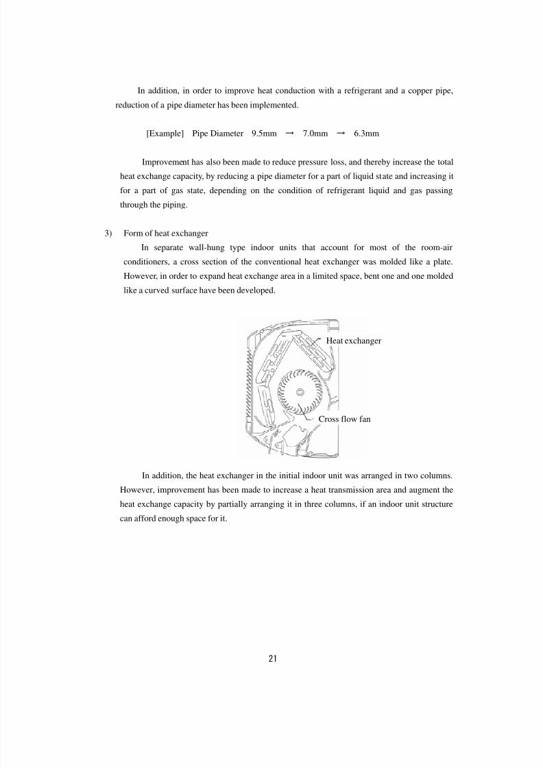
2) Copper tube for heat exchange
Initially, a smooth tube, inner surface of which was not processed like a copper tube,
in general, was used for a heat exchanger. For saving energy, a tube with internal groove
was developed and optimization of a groove shape has been pushed forward.
Smooth Tube Tube with Internal Groove
Optimization of a Groove Shape
8/8/2019 Aircond Report
http://slidepdf.com/reader/full/aircond-report 22/43
21
In addition, in order to improve heat conduction with a refrigerant and a copper pipe,
reduction of a pipe diameter has been implemented.
[Example] Pipe Diameter 9.5mm → 7.0mm → 6.3mm
Improvement has also been made to reduce pressure loss, and thereby increase the total
heat exchange capacity, by reducing a pipe diameter for a part of liquid state and increasing it
for a part of gas state, depending on the condition of refrigerant liquid and gas passing
through the piping.
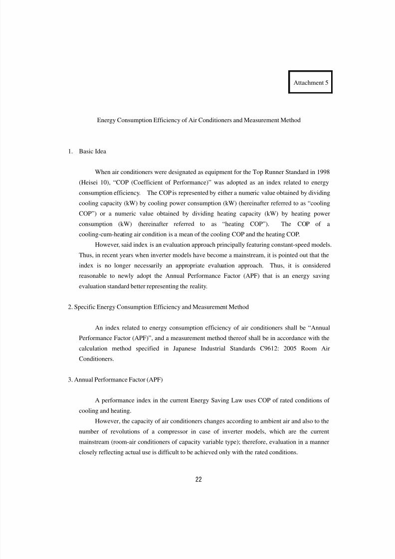
3) Form of heat exchanger
In separate wall-hung type indoor units that account for most of the room-airconditioners, a cross section of the conventional heat exchanger was molded like a plate.
However, in order to expand heat exchange area in a limited space, bent one and one molded
like a curved surface have been developed.
In addition, the heat exchanger in the initial indoor unit was arranged in two columns.
However, improvement has been made to increase a heat transmission area and augment the
heat exchange capacity by partially arranging it in three columns, if an indoor unit structure
can afford enough space for it.
Cross flow fan
Heat exchanger
8/8/2019 Aircond Report
http://slidepdf.com/reader/full/aircond-report 23/43
22
Attachment 5
Energy Consumption Efficiency of Air Conditioners and Measurement Method
1. Basic Idea
When air conditioners were designated as equipment for the Top Runner Standard in 1998
(Heisei 10), “COP (Coefficient of Performance)” was adopted as an index related to energy
consumption efficiency. The COP is represented by either a numeric value obtained by dividing
cooling capacity (kW) by cooling power consumption (kW) (hereinafter referred to as “cooling
COP”) or a numeric value obtained by dividing heating capacity (kW) by heating power
consumption (kW) (hereinafter referred to as “heating COP”). The COP of a
cooling-cum-heating air condition is a mean of the cooling COP and the heating COP.
However, said index is an evaluation approach principally featuring constant-speed models.
Thus, in recent years when inverter models have become a mainstream, it is pointed out that the
index is no longer necessarily an appropriate evaluation approach. Thus, it is considered
reasonable to newly adopt the Annual Performance Factor (APF) that is an energy saving
evaluation standard better representing the reality.
2. Specific Energy Consumption Efficiency and Measurement Method
An index related to energy consumption efficiency of air conditioners shall be “Annual
Performance Factor (APF)”, and a measurement method thereof shall be in accordance with the
calculation method specified in Japanese Industrial Standards C9612: 2005 Room Air
Conditioners.
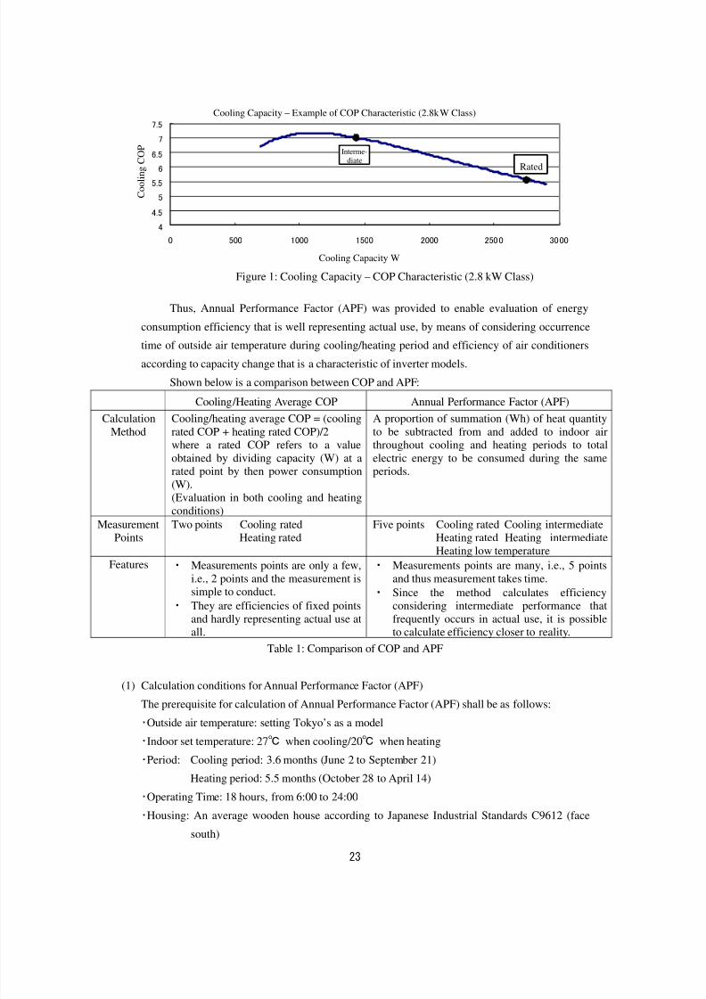
3. Annual Performance Factor (APF)
A performance index in the current Energy Saving Law uses COP of rated conditions of
cooling and heating.
However, the capacity of air conditioners changes according to ambient air and also to the
number of revolutions of a compressor in case of inverter models, which are the current
mainstream (room-air conditioners of capacity variable type); therefore, evaluation in a manner
closely reflecting actual use is difficult to be achieved only with the rated conditions.
8/8/2019 Aircond Report
http://slidepdf.com/reader/full/aircond-report 24/43
23
冷房能力-COP特性の例(2.8kWクラス)
4
4.5
5
5.5
6
6.5
7
7.5
0 500 1000 1500 2000 2500 3000
冷房能力W
冷 房 C O P 中間
定格
Thus, Annual Performance Factor (APF) was provided to enable evaluation of energy
consumption efficiency that is well representing actual use, by means of considering occurrence
time of outside air temperature during cooling/heating period and efficiency of air conditioners
according to capacity change that is a characteristic of inverter models.
Shown below is a comparison between COP and APF:
Cooling/Heating Average COP Annual Performance Factor (APF)
Calculation
Method
Cooling/heating average COP = (cooling
rated COP + heating rated COP)/2where a rated COP refers to a value
obtained by dividing capacity (W) at arated point by then power consumption
(W).(Evaluation in both cooling and heating
conditions)
A proportion of summation (Wh) of heat quantity
to be subtracted from and added to indoor airthroughout cooling and heating periods to total
electric energy to be consumed during the sameperiods.
MeasurementPoints
Two points Cooling ratedHeating rated
Five points Cooling rated Cooling intermediateHeating rated Heating intermediate
Heating low temperature
Features ・ Measurements points are only a few,
i.e., 2 points and the measurement issimple to conduct.
・ They are efficiencies of fixed points
and hardly representing actual use atall.
・ Measurements points are many, i.e., 5 points
and thus measurement takes time.
・ Since the method calculates efficiencyconsidering intermediate performance that
frequently occurs in actual use, it is possibleto calculate efficiency closer to reality.
Table 1: Comparison of COP and APF
(1) Calculation conditions for Annual Performance Factor (APF)
The prerequisite for calculation of Annual Performance Factor (APF) shall be as follows:
・Outside air temperature: setting Tokyo’s as a model
・Indoor set temperature: 27℃ when cooling/20℃ when heating
・Period: Cooling period: 3.6 months (June 2 to September 21)
Heating period: 5.5 months (October 28 to April 14)
・Operating Time: 18 hours, from 6:00 to 24:00
・Housing: An average wooden house according to Japanese Industrial Standards C9612 (face
south)
Figure 1: Cooling Capacity – COP Characteristic (2.8 kW Class)
Cooling Capacity W
Cooling Capacity – Example of COP Characteristic (2.8kW Class)
C o o l i n g C
O P
Interme-
diate Rated
8/8/2019 Aircond Report
http://slidepdf.com/reader/full/aircond-report 25/43
24
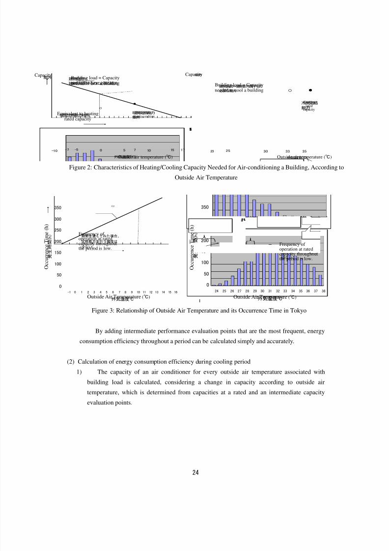
Figure 2: Characteristics of Heating/Cooling Capacity Needed for Air-conditioning a Building, According to
Outside Air Temperature
0
50
100
150
200
250
300
350
-1 0 1 2 3 4 5 6 7 8 9 10 11 12 13 14 15 16
外気温度℃
発 生 時 間 ( h )
0
50
100
150
200
250
300
350
24 25 26 27 28 29 30 31 32 33 34 35 36 37 38
外気温度℃
発 生 時 間 ( h )
Figure 3: Relationship of Outside Air Temperature and its Occurrence Time in Tokyo
By adding intermediate performance evaluation points that are the most frequent, energy
consumption efficiency throughout a period can be calculated simply and accurately.
(2) Calculation of energy consumption efficiency during cooling period
1) The capacity of an air conditioner for every outside air temperature associated with
building load is calculated, considering a change in capacity according to outside air
temperature, which is determined from capacities at a rated and an intermediate capacity
evaluation points.
外気温度(℃)
-7 0 7 17-10 -5 5 10 15
建物負荷=
建物を暖房するのに必要な能力
能力
●
○
暖房定格能力相当暖房定格能力
条件
外気温度(℃)
3525 30
能力
23
建物負荷=建物を冷房するの
必要な能力 ○
33
●
冷房定格
能力
期間を通じてみた場合、
定格能力を行う頻度は
少ない。
期間を通じてみた場合、
定格能力を行う頻度は
少ない。
Building load = Capacityneeded to heat a building Building load = Capacity
needed to cool a building
Equivalent to heatingrated capacity
Heating rated
capacity condition
Outside air temperature (℃) Outside air temperature (℃)
Coolingrated
capacity
Capacity Capacity
Frequency of operation at ratedcapacity throughoutthe period is low.
Frequency of operation at ratedcapacity throughoutthe period is low.
Outside Air Temperature (℃) Outside Air Temperature (℃)
O
c c u r r e n c e T i m e ( h )
O
c c u r r e n c e T i m e ( h )
8/8/2019 Aircond Report
http://slidepdf.com/reader/full/aircond-report 26/43
25
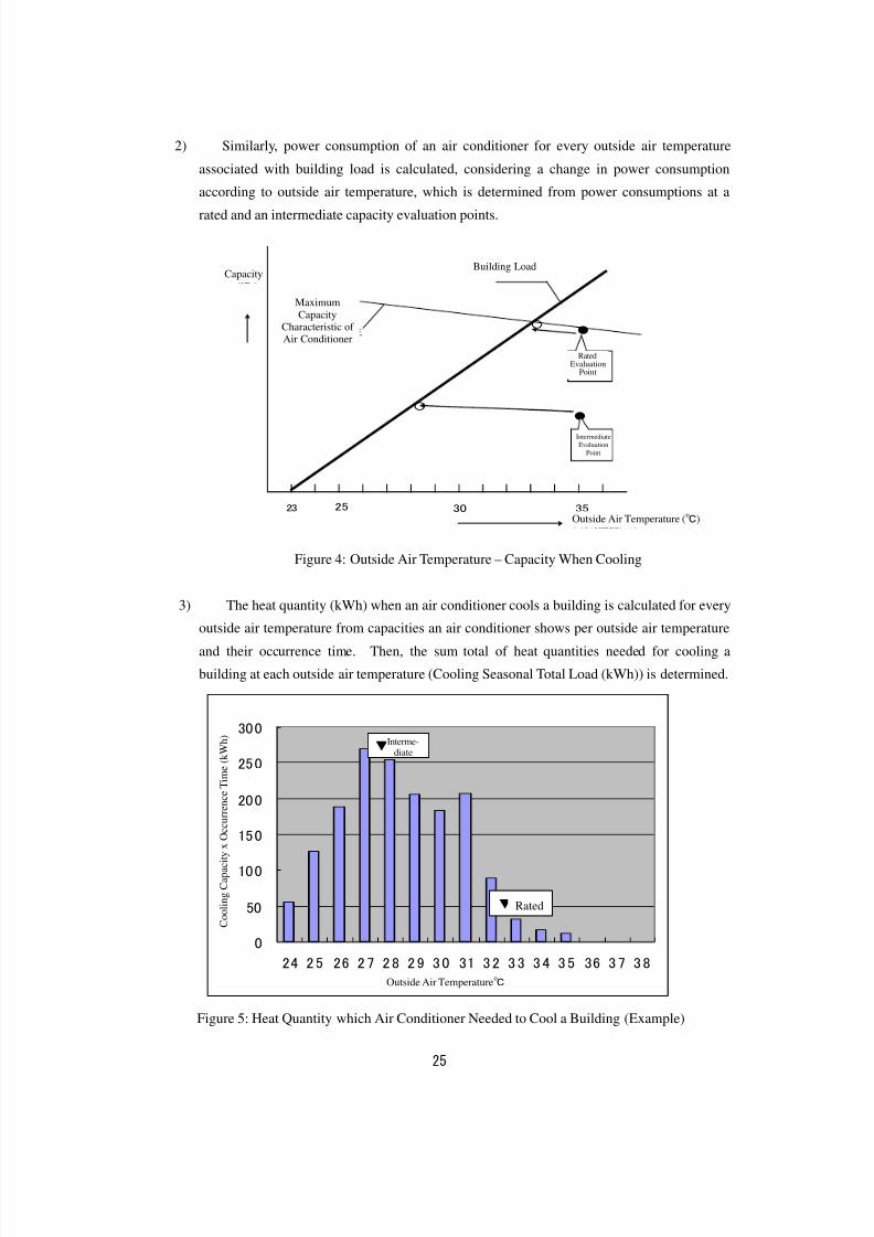
2) Similarly, power consumption of an air conditioner for every outside air temperature
associated with building load is calculated, considering a change in power consumption
according to outside air temperature, which is determined from power consumptions at a
rated and an intermediate capacity evaluation points.
Figure 4: Outside Air Temperature – Capacity When Cooling
3) The heat quantity (kWh) when an air conditioner cools a building is calculated for every
outside air temperature from capacities an air conditioner shows per outside air temperature
and their occurrence time. Then, the sum total of heat quantities needed for cooling a
building at each outside air temperature (Cooling Seasonal Total Load (kWh)) is determined.
0
50
10 0
15 0
20 0
25 0
30 0
24 2 5 26 2 7 2 8 2 9 3 0 31 3 2 3 3 3 4 3 5 36 3 7 3 8
外気温度℃
冷 房 能 力 × 発 生 時 間 ( k W h )
Figure 5: Heat Quantity which Air Conditioner Needed to Cool a Building (Example)
外気温度(℃)
3525 30
能力
●
23
建物負荷
○エアコンの
最大能力特性
●○
定格
評価点
中間
評価点
▼中間
▼定格
Maximum
CapacityCharacteristic of Air Conditioner
Capacity Building Load
RatedEvaluation
Point
Intermediate
Evaluation
Point
Outside Air Temperature (℃)
C o o l i n g C a p a c i t y x O c c u r r e n c e T i m e ( k W h )
Interme-diate
Rated
Outside Air Temperature℃
8/8/2019 Aircond Report
http://slidepdf.com/reader/full/aircond-report 27/43
26
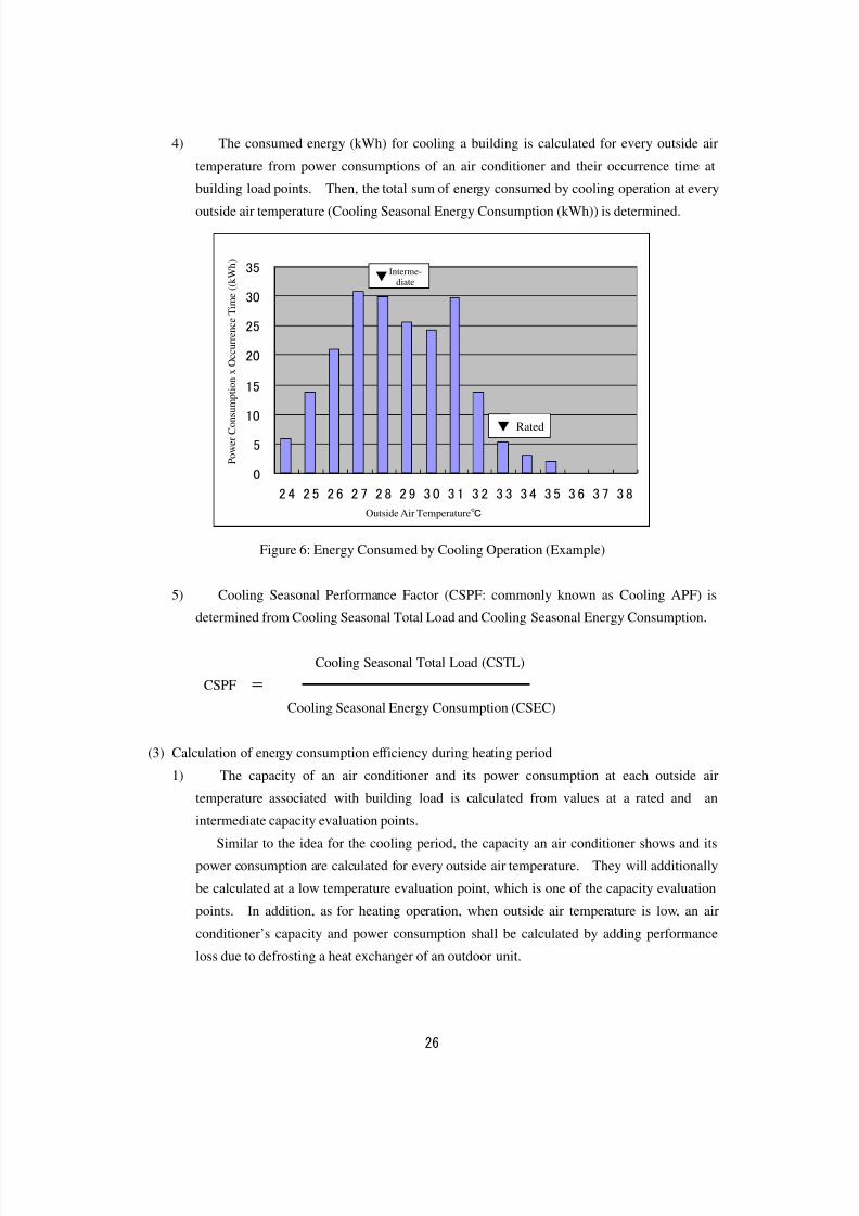
4) The consumed energy (kWh) for cooling a building is calculated for every outside air
temperature from power consumptions of an air conditioner and their occurrence time at
building load points. Then, the total sum of energy consumed by cooling operation at every
outside air temperature (Cooling Seasonal Energy Consumption (kWh)) is determined.
0
5
10
15
20
25
30
35
2 4 2 5 2 6 2 7 2 8 2 9 3 0 3 1 3 2 3 3 3 4 3 5 3 6 3 7 3 8
外気温度℃
消 費 電 力 × 発 生 時 間 ( k W h )
Figure 6: Energy Consumed by Cooling Operation (Example)
5) Cooling Seasonal Performance Factor (CSPF: commonly known as Cooling APF) is
determined from Cooling Seasonal Total Load and Cooling Seasonal Energy Consumption.
Cooling Seasonal Total Load (CSTL)
CSPF =
Cooling Seasonal Energy Consumption (CSEC)
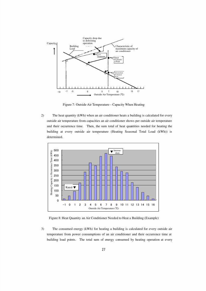
(3) Calculation of energy consumption efficiency during heating period
1) The capacity of an air conditioner and its power consumption at each outside air
temperature associated with building load is calculated from values at a rated and an
intermediate capacity evaluation points.
Similar to the idea for the cooling period, the capacity an air conditioner shows and its
power consumption are calculated for every outside air temperature. They will additionally
be calculated at a low temperature evaluation point, which is one of the capacity evaluation
points. In addition, as for heating operation, when outside air temperature is low, an air
conditioner’s capacity and power consumption shall be calculated by adding performance
loss due to defrosting a heat exchanger of an outdoor unit.
▼中間
▼定格
P o w e r C o n s u m p t i o n x O c c u r r e n c e T i m e ( ( k W h )
Interme-diate
Rated
Outside Air Temperature℃
8/8/2019 Aircond Report
http://slidepdf.com/reader/full/aircond-report 28/43
27
Figure 7: Outside Air Temperature – Capacity When Heating
2) The heat quantity (kWh) when an air conditioner heats a building is calculated for every
outside air temperature from capacities an air conditioner shows per outside air temperature
and their occurrence time. Then, the sum total of heat quantities needed for heating the
building at every outside air temperature (Heating Seasonal Total Load (kWh)) is
determined.
0
50
100
150
200
250
300
350
400
450
500
-1 0 1 2 3 4 5 6 7 8 9 10 11 12 13 14 15 16
外気温度℃
暖 房
能 力 × 発 生 時 間 ( k W h )
Figure 8: Heat Quantity an Air Conditioner Needed to Heat a Building (Example)
3) The consumed energy (kWh) for heating a building is calculated for every outside air
temperature from power consumptions of an air conditioner and their occurrence time at
building load points. The total sum of energy consumed by heating operation at every
外気温度(℃)
-7 0 7 17-10 -5 5 10 15
●
●
○
建物負荷
●
エアコンの
最大能力特性
能力
○
○
霜取り運転によ
る能力ダウン
定格評価点
中間評価点
低温
▼中間
定格▼
H e a t i n g C a p a c i t y x O c c u r r e n c e T i m e ( k W h ) Interme-
diate
Rated
Outside Air Temperature (℃)
Capacity
BuildingLoad
Capacity drop dueto defrostingoperation
Characteristic of maximum capacity of air conditioner
Low
TemperaturRatedEvaluation Point
Intermediate
Evaluation
Point
Outside Air Temperature (℃)
8/8/2019 Aircond Report
http://slidepdf.com/reader/full/aircond-report 29/43
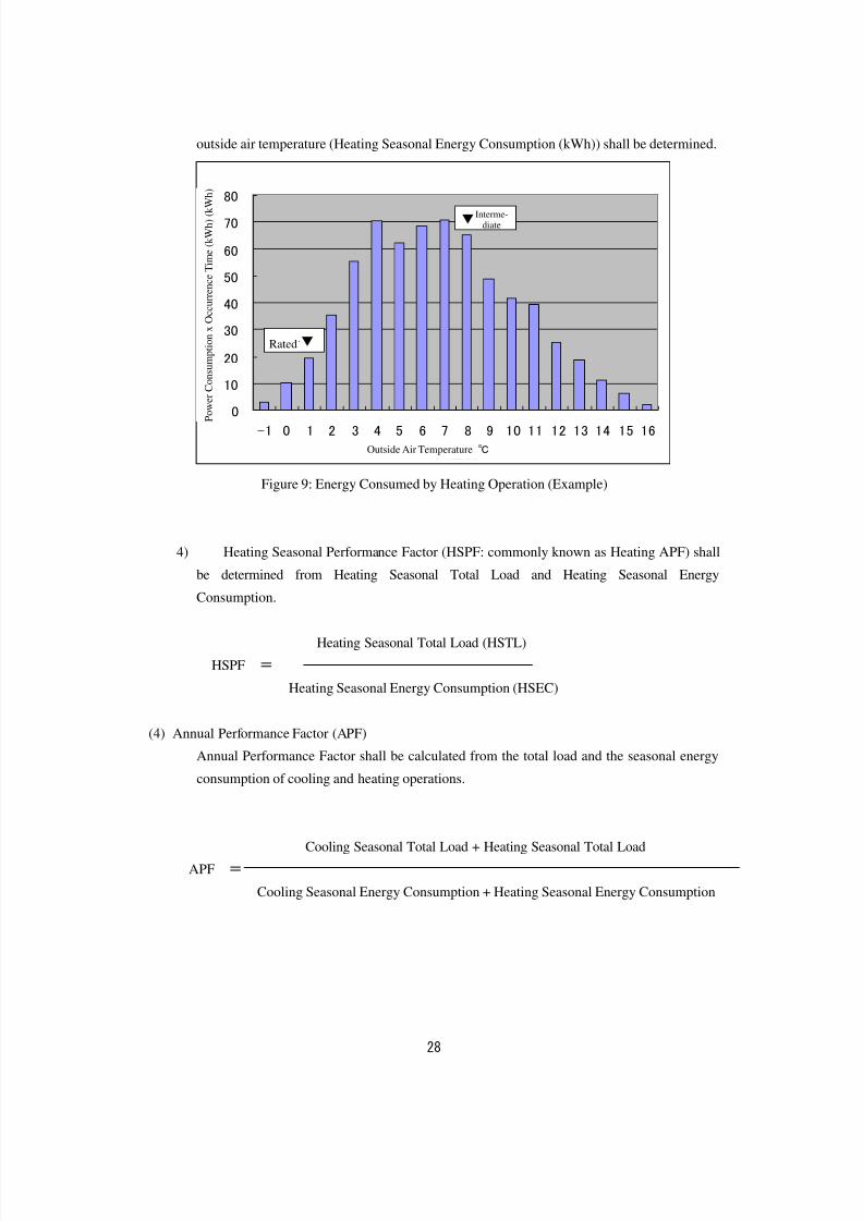
28
outside air temperature (Heating Seasonal Energy Consumption (kWh)) shall be determined.
0
10
20
30
40
50
60
70
80
-1 0 1 2 3 4 5 6 7 8 9 10 11 12 13 14 15 16
外気温度℃
消 費 電 力 × 発 生 時 間 ( k W h )
Figure 9: Energy Consumed by Heating Operation (Example)
4) Heating Seasonal Performance Factor (HSPF: commonly known as Heating APF) shall
be determined from Heating Seasonal Total Load and Heating Seasonal Energy
Consumption.
Heating Seasonal Total Load (HSTL)
HSPF =
Heating Seasonal Energy Consumption (HSEC)
(4) Annual Performance Factor (APF)
Annual Performance Factor shall be calculated from the total load and the seasonal energy
consumption of cooling and heating operations.
Cooling Seasonal Total Load + Heating Seasonal Total Load
APF =
Cooling Seasonal Energy Consumption + Heating Seasonal Energy Consumption
▼中間
定格▼
P o w e r
C o n s u m p t i o n x O c c u r r e n c e T i m e ( k W h ) ( k W h )
Interme-diate
Rated
Outside Air Temperature ℃
8/8/2019 Aircond Report
http://slidepdf.com/reader/full/aircond-report 30/43
29
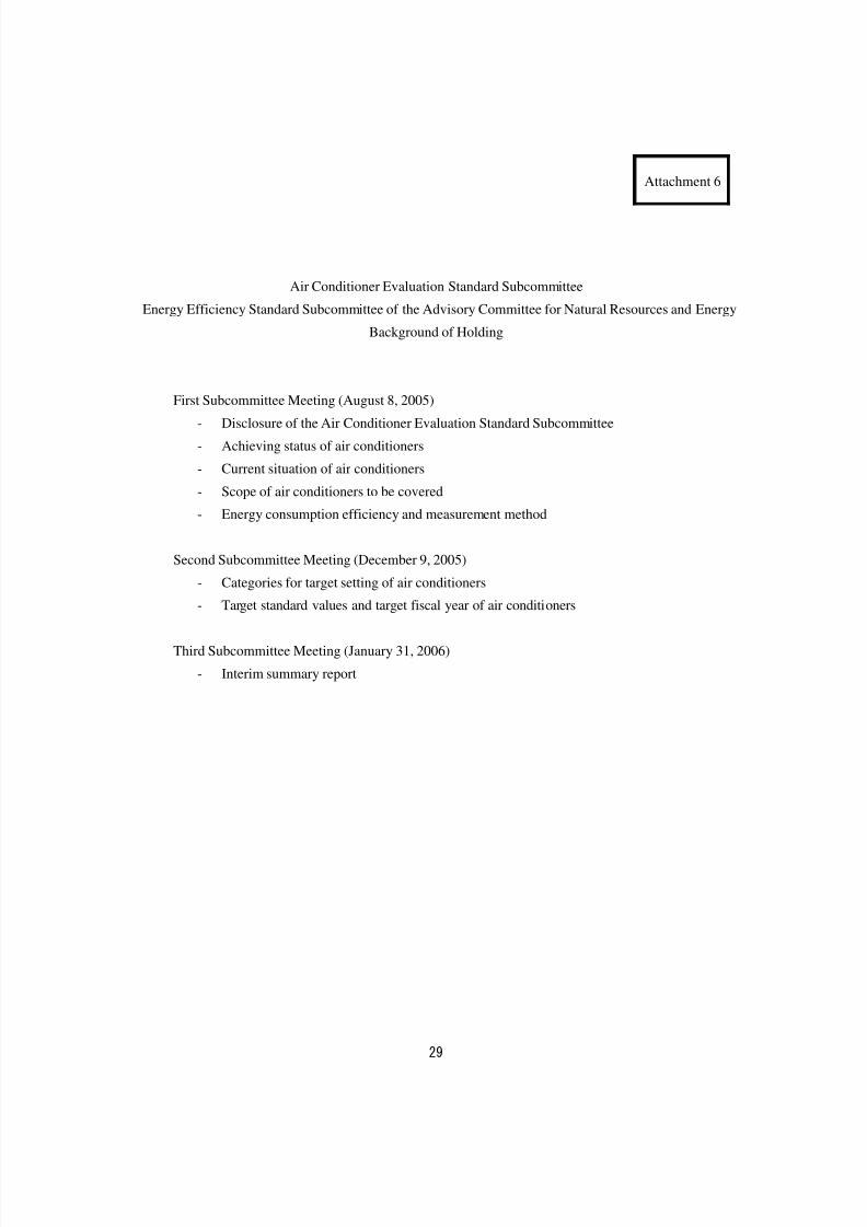
Attachment 6
Air Conditioner Evaluation Standard Subcommittee
Energy Efficiency Standard Subcommittee of the Advisory Committee for Natural Resources and Energy
Background of Holding
First Subcommittee Meeting (August 8, 2005)
- Disclosure of the Air Conditioner Evaluation Standard Subcommittee
- Achieving status of air conditioners
- Current situation of air conditioners
- Scope of air conditioners to be covered
- Energy consumption efficiency and measurement method
Second Subcommittee Meeting (December 9, 2005)
- Categories for target setting of air conditioners
- Target standard values and target fiscal year of air conditioners
Third Subcommittee Meeting (January 31, 2006)
- Interim summary report
8/8/2019 Aircond Report
http://slidepdf.com/reader/full/aircond-report 31/43
30
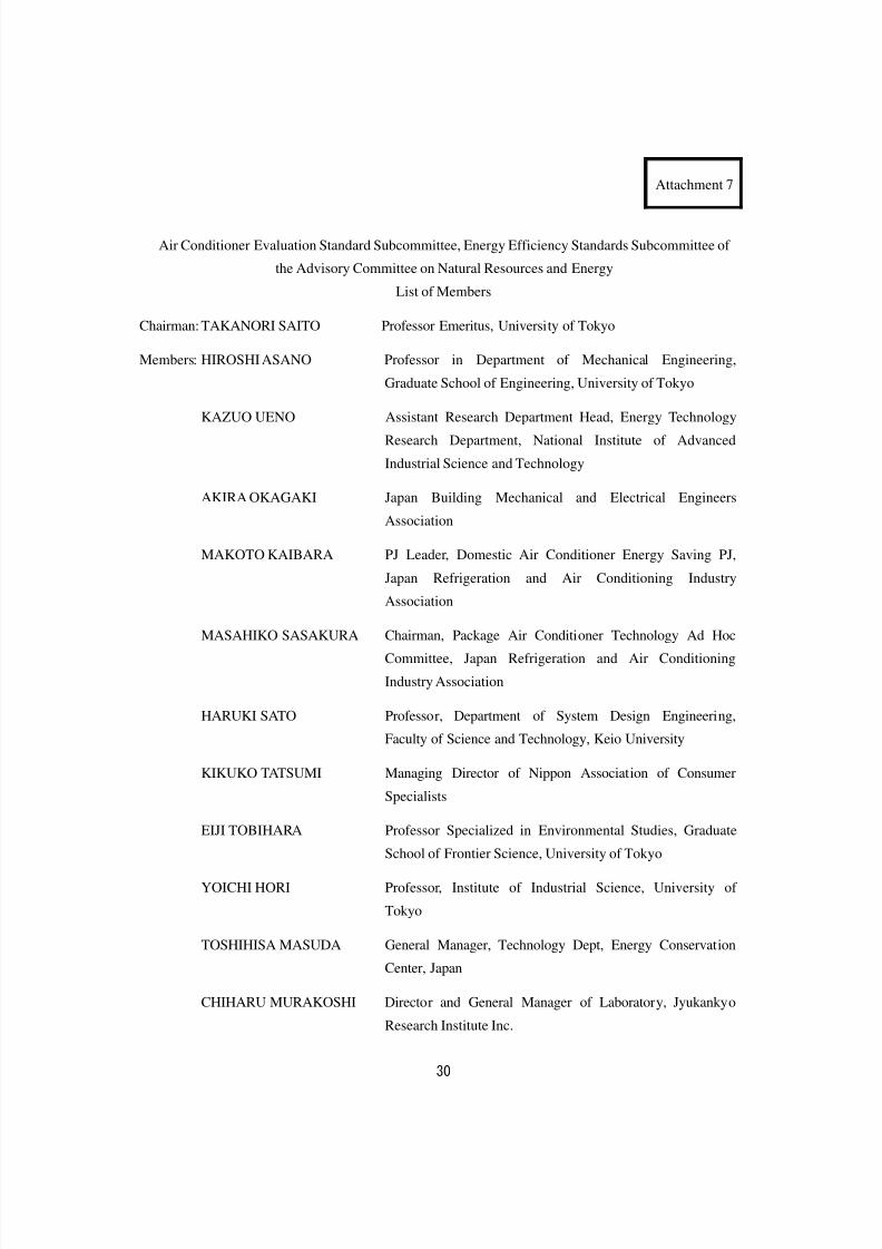
Attachment 7
Air Conditioner Evaluation Standard Subcommittee, Energy Efficiency Standards Subcommittee of
the Advisory Committee on Natural Resources and Energy
List of Members
Chairman: TAKANORI SAITO Professor Emeritus, University of Tokyo
Members: HIROSHI ASANO Professor in Department of Mechanical Engineering,
Graduate School of Engineering, University of Tokyo
KAZUO UENO Assistant Research Department Head, Energy Technology
Research Department, National Institute of Advanced
Industrial Science and Technology
AKIRA OKAGAKI Japan Building Mechanical and Electrical Engineers
Association
MAKOTO KAIBARA PJ Leader, Domestic Air Conditioner Energy Saving PJ,
Japan Refrigeration and Air Conditioning Industry
Association
MASAHIKO SASAKURA Chairman, Package Air Conditioner Technology Ad Hoc
Committee, Japan Refrigeration and Air Conditioning
Industry Association
HARUKI SATO Professor, Department of System Design Engineering,
Faculty of Science and Technology, Keio University
KIKUKO TATSUMI Managing Director of Nippon Association of Consumer
Specialists
EIJI TOBIHARA Professor Specialized in Environmental Studies, Graduate
School of Frontier Science, University of Tokyo
YOICHI HORI Professor, Institute of Industrial Science, University of
Tokyo
TOSHIHISA MASUDA General Manager, Technology Dept, Energy Conservation
Center, Japan
CHIHARU MURAKOSHI Director and General Manager of Laboratory, Jyukankyo
Research Institute Inc.
8/8/2019 Aircond Report
http://slidepdf.com/reader/full/aircond-report 32/43
31
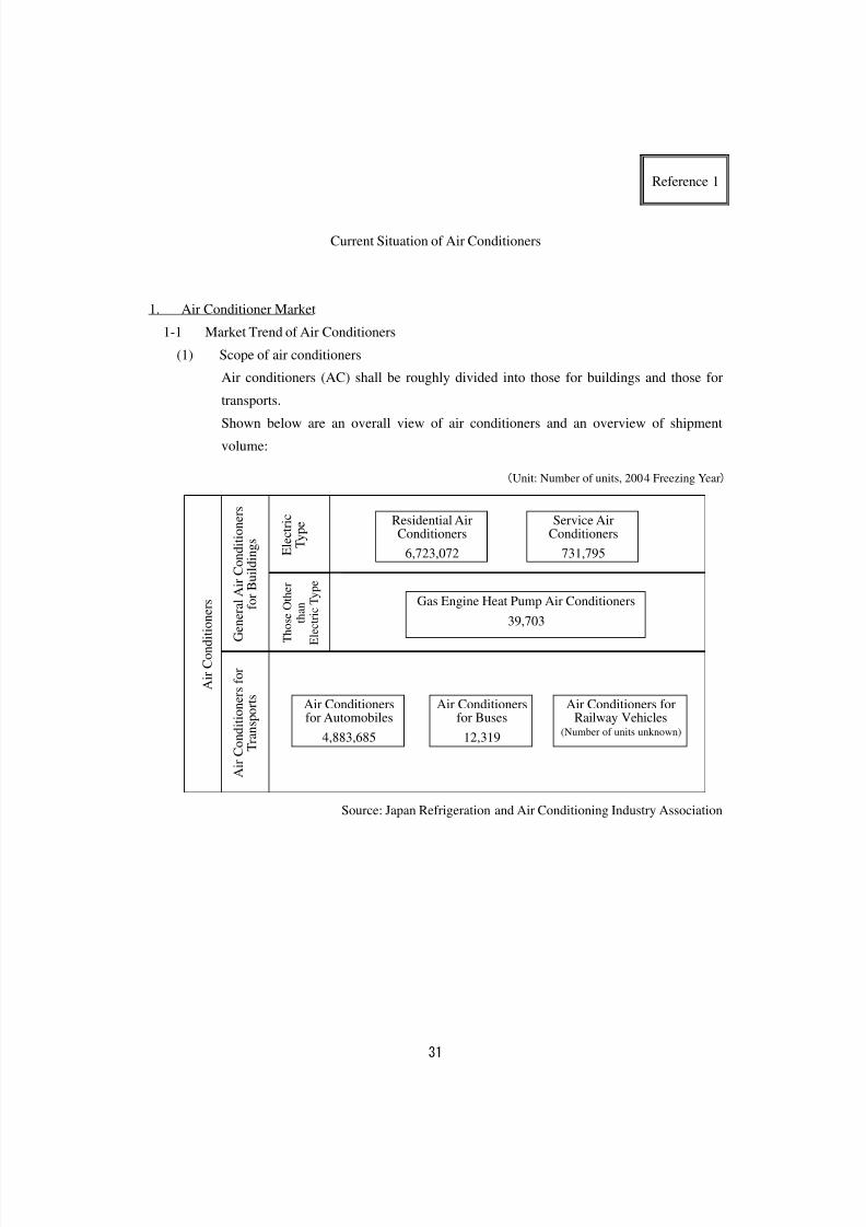
Reference 1
Current Situation of Air Conditioners
1. Air Conditioner Market
1-1 Market Trend of Air Conditioners
(1) Scope of air conditioners
Air conditioners (AC) shall be roughly divided into those for buildings and those for
transports.
Shown below are an overall view of air conditioners and an overview of shipment
volume:
Source: Japan Refrigeration and Air Conditioning Industry Association
(Unit: Number of units, 2004 Freezing Year)
E l e c t r i c
T y p e
Gas Engine Heat Pump Air Conditioners
39,703
Air Conditionersfor Automobiles
4,883,685
Air Conditionersfor Buses
12,319
Air Conditioners forRailway Vehicles
(Number of units unknown)
Residential AirConditioners
6,723,072
Service AirConditioners
731,795
A i r C o n d i t i o n e r s
G e n e r a l A i r C o n d i t i o n e r s
f o r
B u i l d i n g s
A i r C o n d i t i o n e r s f o r
T r a n s p o r t s
T h o s e O t h
e r
t h a n
E l e c t r i c T y
p e
8/8/2019 Aircond Report
http://slidepdf.com/reader/full/aircond-report 33/43
32
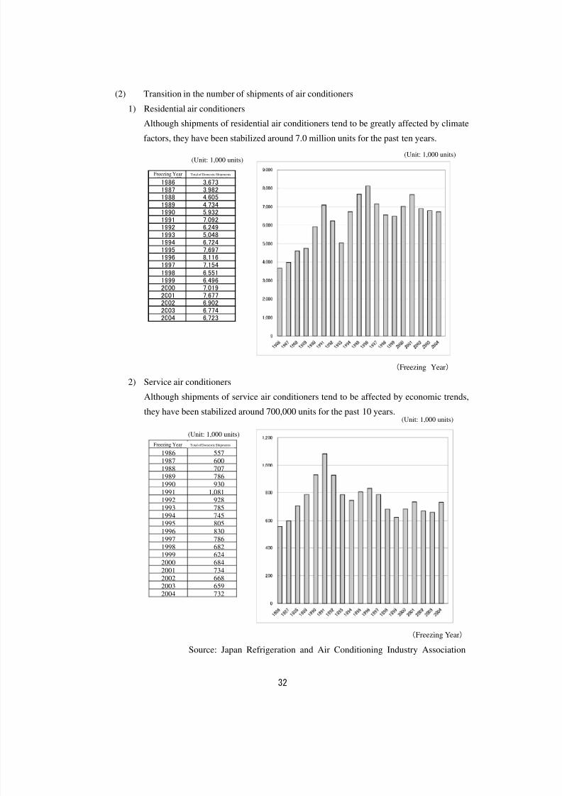
(2) Transition in the number of shipments of air conditioners
1) Residential air conditioners
Although shipments of residential air conditioners tend to be greatly affected by climate
factors, they have been stabilized around 7.0 million units for the past ten years.
(Freezing Year)
2) Service air conditioners
Although shipments of service air conditioners tend to be affected by economic trends,
they have been stabilized around 700,000 units for the past 10 years.
冷凍年度 国内出荷合計1986 5571987 6001988 7071989 7861990 930
1991 1,0811992 9281993 785
1994 7451995 805
1996 8301997 7861998 6821999 6242000 684
2001 7342002 6682003 6592004 732
(Freezing Year)
Source: Japan Refrigeration and Air Conditioning Industry Association
(Unit: 1,000 units)
冷凍年度 国内出荷合計1986 3,6731987 3,9821988 4,6051989 4,7341990 5,9321991 7,0921992 6,2491993 5,0481994 6,7241995 7,697
1996 8,1161997 7,1541998 6,5511999 6,4962000 7,0192001 7,6772002 6,9022003 6,7742004 6,723
(Unit: 1,000 units)
(Unit: 1,000 units)
(Unit: 1,000 units)
Freezing Year Total of Domestic Shipments
Freezing Year Total of Domestic Shipments
8/8/2019 Aircond Report
http://slidepdf.com/reader/full/aircond-report 34/43
33
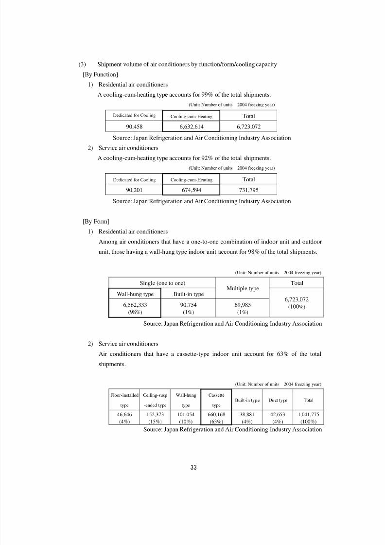
(3) Shipment volume of air conditioners by function/form/cooling capacity
[By Function]
1) Residential air conditioners
A cooling-cum-heating type accounts for 99% of the total shipments.
(Unit: Number of units 2004 freezing year)
Dedicated for Cooling Cooling-cum-Heating Total
90,458 6,632,614 6,723,072
Source: Japan Refrigeration and Air Conditioning Industry Association
2) Service air conditioners
A cooling-cum-heating type accounts for 92% of the total shipments.
(Unit: Number of units 2004 freezing year)
Dedicated for Cooling Cooling-cum-Heating Total
90,201 674,594 731,795
Source: Japan Refrigeration and Air Conditioning Industry Association
[By Form]
1) Residential air conditioners
Among air conditioners that have a one-to-one combination of indoor unit and outdoor
unit, those having a wall-hung type indoor unit account for 98% of the total shipments.
(Unit: Number of units 2004 freezing year)
Single (one to one) Total
Wall-hung type Built-in typeMultiple type
6,562,333
(98%)
90,754
(1%)
69,985
(1%)
6,723,072
(100%)
Source: Japan Refrigeration and Air Conditioning Industry Association
2) Service air conditioners
Air conditioners that have a cassette-type indoor unit account for 63% of the total
shipments.
(Unit: Number of units 2004 freezing year)
Floor-installed
type
Ceiling-susp
-ended type
Wall-hung
type
Cassette
type Built-in type Duct type Total
46,646
(4%)
152,373
(15%)
101,054
(10%)
660,168
(63%)
38,881
(4%)
42,653
(4%)
1,041,775
(100%)
Source: Japan Refrigeration and Air Conditioning Industry Association
8/8/2019 Aircond Report
http://slidepdf.com/reader/full/aircond-report 35/43
34
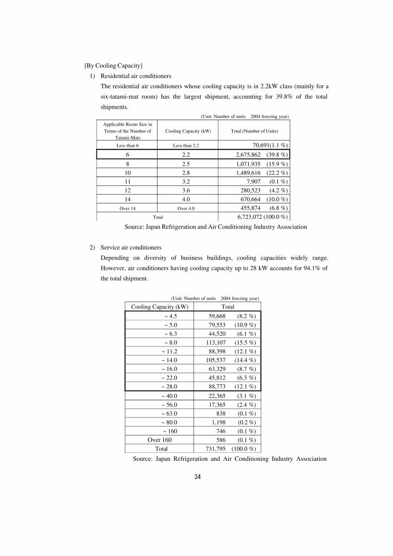
[By Cooling Capacity]
1) Residential air conditioners
The residential air conditioners whose cooling capacity is in 2.2kW class (mainly for a
six-tatami-mat room) has the largest shipment, accounting for 39.8% of the total
shipments.
(Unit: Number of units 2004 freezing year)
Applicable Room Size in
Terms of the Number of
Tatami-Mats Cooling Capacity (kW) Total (Number of Units)
Less than 6 Less than 2.2 70,691(1.1 %)
6 2.2 2,675,862 (39.8 %)
8 2.5 1,071,935 (15.9 %)
10 2.8 1,489,616 (22.2 %)
11 3.2 7,907 (0.1 %)
12 3.6 280,523 (4.2 %)
14 4.0 670,664 (10.0 %)
Over 14 Over 4.0 455,874 (6.8 %)
Total 6,723,072 (100.0 %)
Source: Japan Refrigeration and Air Conditioning Industry Association
2) Service air conditioners
Depending on diversity of business buildings, cooling capacities widely range.
However, air conditioners having cooling capacity up to 28 kW accounts for 94.1% of the total shipment.
(Unit: Number of units 2004 freezing year)
Cooling Capacity (kW) Total
~ 4.5 59,668 (8.2 %)
~ 5.0 79,553 (10.9 %)
~ 6.3 44,520 (6.1 %)
~ 8.0 113,107 (15.5 %)
~ 11.2 88,398 (12.1 %)
~ 14.0 105,537 (14.4 %)~ 16.0 63,329 (8.7 %)
~ 22.0 45,812 (6.3 %)
~ 28.0 88,773 (12.1 %)
~ 40.0 22,365 (3.1 %)
~ 56.0 17,365 (2.4 %)
~ 63.0 838 (0.1 %)
~ 80.0 1,198 (0.2 %)
~ 160 746 (0.1 %)
Over 160 586 (0.1 %)
Total 731,795 (100.0 %)Source: Japan Refrigeration and Air Conditioning Industry Association
8/8/2019 Aircond Report
http://slidepdf.com/reader/full/aircond-report 36/43
35
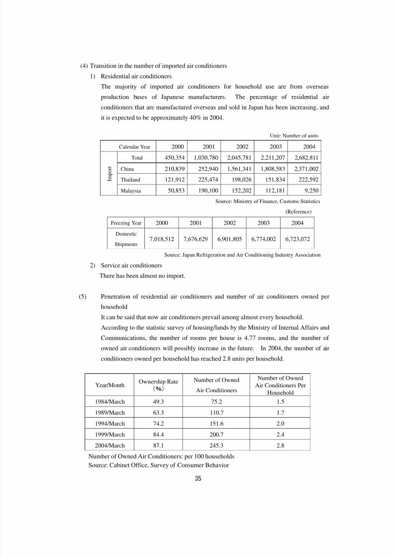
(4) Transition in the number of imported air conditioners
1) Residential air conditioners
The majority of imported air conditioners for household use are from overseas
production bases of Japanese manufacturers. The percentage of residential air
conditioners that are manufactured overseas and sold in Japan has been increasing, and
it is expected to be approximately 40% in 2004.
Unit: Number of units
Calendar Year 2000 2001 2002 2003 2004
Total 450,354 1,030,780 2,045,781 2,211,207 2,682,811
China 210,839 252,940 1,561,341 1,808,583 2,371,002
Thailand 121,912 225,474 198,026 151,834 222,592 I
m p o r t
Malaysia 50,853 190,100 152,202 112,181 9,250
Source: Ministry of Finance, Customs Statistics
(Reference)
Freezing Year 2000 2001 2002 2003 2004
Domestic
Shipments 7,018,512 7,676,629 6,901,805 6,774,002 6,723,072
Source: Japan Refrigeration and Air Conditioning Industry Association
2) Service air conditioners
There has been almost no import.
(5) Penetration of residential air conditioners and number of air conditioners owned per
household
It can be said that now air conditioners prevail among almost every household.
According to the statistic survey of housing/lands by the Ministry of Internal Affairs and
Communications, the number of rooms per house is 4.77 rooms, and the number of
owned air conditioners will possibly increase in the future. In 2004, the number of air
conditioners owned per household has reached 2.8 units per household.
Year/MonthOwnership Rate
(%)
Number of Owned
Air Conditioners
Number of Owned
Air Conditioners Per
Household
1984/March 49.3 75.2 1.5
1989/March 63.3 110.7 1.7
1994/March 74.2 151.6 2.0
1999/March 84.4 200.7 2.4
2004/March 87.1 245.3 2.8
Number of Owned Air Conditioners: per 100 households
Source: Cabinet Office, Survey of Consumer Behavior
8/8/2019 Aircond Report
http://slidepdf.com/reader/full/aircond-report 37/43
36
1-2 Main Domestic Manufacturers
1. Residential Air Conditioners
・Corona Corporation
・Sanyo Electric Air Conditioning Co., Ltd.
・Sharp Corporation
・Daikin Industries, Ltd.
・Chofu Seisakusho Co., Ltd.
・Toshiba Carrier Corporation
・Hitachi Appliance, Inc.
・Fujitsu General Co., Ltd.
・Matsushita Electric Industrial Co., Ltd.
・Mitsubishi Heavy Industries, Ltd. ,・Mitsubishi Electric Corporation
(In the order of Japanese Syllabary)
2. Service Air Conditioners
・Sanyo Electric Co., Ltd.
・GAC Corporation
・Sharp Corporation
・Daikin Industries, Ltd.
・Toshiba Carrier Corporation
・Nippon PMAC Co., Ltd.
・Hitachi Appliance, Inc.
・Matsushita Electric Industrial Co., Ltd.
・Mitsubishi Heavy Industries, Ltd.
・Mitsubishi Electric Corporation
(In the order of Japanese Syllabary)
8/8/2019 Aircond Report
http://slidepdf.com/reader/full/aircond-report 38/43
37
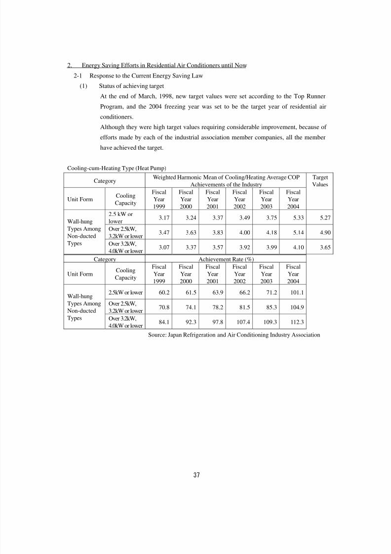
2. Energy Saving Efforts in Residential Air Conditioners until Now
2-1 Response to the Current Energy Saving Law
(1) Status of achieving target
At the end of March, 1998, new target values were set according to the Top Runner
Program, and the 2004 freezing year was set to be the target year of residential air
conditioners.
Although they were high target values requiring considerable improvement, because of
efforts made by each of the industrial association member companies, all the member
have achieved the target.
Cooling-cum-Heating Type (Heat Pump)
Category Weighted Harmonic Mean of Cooling/Heating Average COPAchievements of the Industry TargetValues
Unit FormCooling
Capacity
Fiscal
Year
1999
Fiscal
Year
2000
Fiscal
Year
2001
Fiscal
Year
2002
Fiscal
Year
2003
Fiscal
Year
2004
2.5 kW or
lower3.17 3.24 3.37 3.49 3.75 5.33 5.27
Over 2.5kW,
3.2kW or lower3.47 3.63 3.83 4.00 4.18 5.14 4.90
Wall-hung
Types Among
Non-ducted
Types Over 3.2kW,
4.0kW or lower3.07 3.37 3.57 3.92 3.99 4.10 3.65
Category Achievement Rate (%)
Unit Form CoolingCapacity
FiscalYear
1999
FiscalYear
2000
FiscalYear
2001
FiscalYear
2002
FiscalYear
2003
FiscalYear
2004
2.5kW or lower 60.2 61.5 63.9 66.2 71.2 101.1
Over 2.5kW,
3.2kW or lower70.8 74.1 78.2 81.5 85.3 104.9
Wall-hung
Types Among
Non-ducted
Types Over 3.2kW,
4.0kW or lower84.1 92.3 97.8 107.4 109.3 112.3
Source: Japan Refrigeration and Air Conditioning Industry Association
8/8/2019 Aircond Report
http://slidepdf.com/reader/full/aircond-report 39/43
38
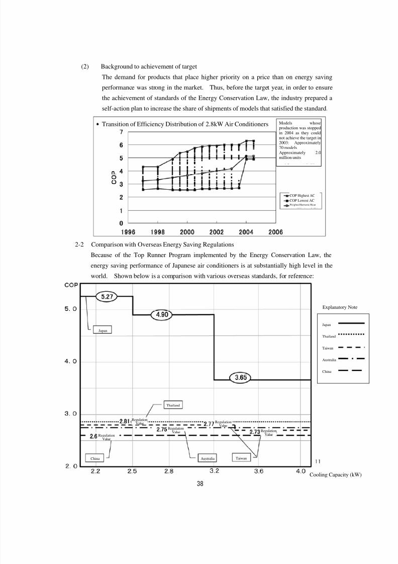
(2) Background to achievement of target
The demand for products that place higher priority on a price than on energy saving
performance was strong in the market. Thus, before the target year, in order to ensure
the achievement of standards of the Energy Conservation Law, the industry prepared a
self-action plan to increase the share of shipments of models that satisfied the standard.
2-2 Comparison with Overseas Energy Saving Regulations
Because of the Top Runner Program implemented by the Energy Conservation Law, the
energy saving performance of Japanese air conditioners is at substantially high level in the
world. Shown below is a comparison with various overseas standards, for reference:
Japan
Thailand
Taiwan
Australia
China
Explanatory Note
Transition of Efficiency Distribution of 2.8kW Air Conditioners Models whoseproduction was stoppedin 2004 as they couldnot achieve the target in2003: Approximately70 modelsApproximately 2.0million units
COP Highest AC
COP Lowest ACWeighted Harmonic Mean
Japan
Thailand
China Australia Taiwan
RegulationValue
RegulationValue
RegulationValue
RegulationValue
RegulationValue
Cooling Capacity (kW)
8/8/2019 Aircond Report
http://slidepdf.com/reader/full/aircond-report 40/43
39
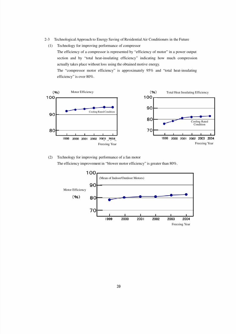
2-3 Technological Approach to Energy Saving of Residential Air Conditioners in the Future
(1) Technology for improving performance of compressor
The efficiency of a compressor is represented by “efficiency of motor” in a power output
section and by “total heat-insulating efficiency” indicating how much compression
actually takes place without loss using the obtained motive energy.
The “compressor motor efficiency” is approximately 95% and “total heat-insulating
efficiency” is over 80%.
(社)日本冷凍空調工業会調べ
(2) Technology for improving performance of a fan motor
The efficiency improvement in “blower motor efficiency” is greater than 80%.
(社)日本冷凍空調工業会調べ
Motor Efficiency Total Heat Insulating Efficiency
Cooling Rated Condition
Cooling RatedCondition
(Mean of Indoor/Outdoor Motors)
Motor Efficiency
Freezing Year
Freezing Year Freezing Year
8/8/2019 Aircond Report
http://slidepdf.com/reader/full/aircond-report 41/43
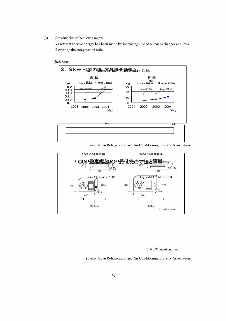
40
(3) Growing size of heat exchangers
An attempt to save energy has been made by increasing size of a heat exchanger and thus
alleviating the compression ratio.
(Reference)
Source: Japan Refrigeration and Air Conditioning Industry Association
(社)日本冷凍空調工業会調べ
Source: Japan Refrigeration and Air Conditioning Industry Association
8
COP最高機とCOP最低機の寸法と質量
Total of Values for Indoor and Outdoor Units
Cubic Capacity
Highest-COP AC Lowest-COP AC
Year
Highest-COP AC Lowest-COP AC
Mass
Year
Dimensions and Mass of Highest-COP and Lowest-COP Air Conditioners
Lowest-COP AC in 2002 Highest-COP AC in 2004
Unit of Dimensions: mm
8/8/2019 Aircond Report
http://slidepdf.com/reader/full/aircond-report 42/43
41
2-4 Approach to Reduction of Standby Power Consumption
(1) Independent declaration by the industry
In January 2001, Japan Electronics and Information Technology Industries Association,
Japan Electrical Manufacturers’ Association, and Japan Refrigeration and Air Conditioning
Industry Association made an independent declaration for reducing standby power
consumption. It stated that for anchor products of residential air conditioners, “they will
make efforts toward the target which is to decrease the standby power consumption below
1W by 2004 freezing year”.
(2) Status at the end of 2004 freezing year in response to the independent declaration of the
industry
Targeted models 191 models
Achieved models 191 modelsAchievement rate 100%
Mean of Standby power consumption 0.81W
8/8/2019 Aircond Report
http://slidepdf.com/reader/full/aircond-report 43/43
3. Future Approach to Energy Saving and Challenges
As it now stands, improvement of energy saving by increasing size of a heat exchanger is a key
factor.
3-1 Various Problems Accompanying Growing Size of Air Conditioners
(1) Installability
Considering the fact that intra-column dimension of half-ken width (“ken” is a unit in
Shaku-kan method) of a Japanese house is 800 mm, it is concerned that an air conditioner
will not be suitable for being used as household equipment if its width exceeds 800 mm.
(2) Comfort
It is concerned that the further growth in size of a “heat exchanger/blower” might damage
the basic comfort; such as, “evaporation temperature rises and thus humidity in a room is
difficult to be cleared” in the case of cooling operation.(3) Resource saving
Increased size of equipment might also increase usage of copper and aluminum, in
particular, which are materials for a heat exchanger. Thus, from the standpoint of resource
saving, the problem still remains.
3-2 Relationship between Difference in Running Cost and Sales Price
In order to actualize the efficiency of an energy saving model for the next generation, it is essential to
increase size of a heat exchanger, which leads to cost increase for material input. Hence, it is
concerned that it will not be possible to offset a difference in the initial cost between energy saving
models and others even with a difference in running cost for 10 years between them.