universiti putra malaysia a neural … · masalah ini mungkin tidak selalunya selaras dengan...
TRANSCRIPT
UNIVERSITI PUTRA MALAYSIA
A NEURAL NETWORK SOLUTION TO SINGULAR CONFIGURATION IN
TRAJECTORY TRACKING OF A SERIAL ROBOT
ALI T. HASAN
FK 2009 56

A NEURAL NETWORK SOLUTION TO SINGULAR CONFIGURATION
IN TRAJECTORY TRACKING OF A SERIAL ROBOT
By ALI T. HASAN
Thesis Submitted to the School of Graduate Studies, Universiti Putra Malaysia, in Fulfilments of the Requirements for the Degree of Doctor of Philosophy
September 2009

DEDICATION
A Special Dedication To
My Family
ii
Abstract of thesis presented to the Senate of Universiti Putra Malaysia in fulfilment of the requirements for the degree of Doctor of Philosophy
A NEURAL NETWORK SOLUTION TO SINGULAR CONFIGURATION IN TRAJECTORY TRACKING OF A SERIAL ROBOT
By
ALI T. HASAN
September 2009
Chairman: Associate Professor Napsiah Ismail, PhD
Faculty: Engineering
Singularities and uncertainties in arm configurations are the main problems in
kinematics of serial robots. The complexity in the solution arises from robots
geometry and non-linear equations (trigonometric equations) occur when
transforming between Cartesian and joint spaces where multiple solutions and
singularities exist. Mathematical solutions for the problem may not always
correspond to the physical solution and methods of solution depend on the robot
configuration.
In this research, a trajectory tracking approach is proposed for a 6 Degrees Of
Freedom (DOF) serial robot manipulator. The proposed solution is carried out
through two stages. First the kinematics model of the Fanuc robot was
solved using the D-H method to show the exact location of singular
iM 710
iii
configurations of the robot, and then Artificial Neural Networks (ANNs) are
trained to overcome these arising problems. Solving the Inverse Kinematics (IK)
of serial manipulators by using ANNs has two problems, one of these is the
selection of the appropriate configuration of the network and the other is the
generating of suitable training data sets.
In this research, although this is very difficult in practice, training data were
recorded experimentally from sensors fixed on each joint to overcome the effect
of kinematics uncertainties presence in the real world such as ill-defined linkage
parameters, links flexibility and backlashes in gear train. Off-line training was
implemented for the experimentally obtained training data.
Two networks configurations from the literature were tested and developed
following the recommendations of the original authors, then compared to find the
best configuration to be used. First the effect of orientation of the tool was
examined (as one of the networks does not considered the effect of orientation
while the other network does), and then the effect of the Jacobian matrix to the
solution for the both configurations was examined.
Performance comparison shows that when the effect of the orientation of the
tool was considered in the solution with the Jacobian matrix effect, better results
in terms of precision and iteration during training the ANN were obtained.
iv
The effect of the network architecture was also examined in order to find the
best network configuration to solve the problem. A network with all the
parameters considered together in one network has been compared to six
different networks, where the parameters of every joint were considered
independently. Results obtained show that having one network considering all
the problem’s parameters together give a better response than using 6 different
networks representing the parameters of each joint apart from other joints.
The resultant network with the best configuration was tested experimentally
using new different set of data that has never been introduced to the network
before, this data set was meant to pass through the singular configurations, in
order to show the generality and efficiency of the proposed approach.
Experimental trajectory tracking has shown the ability of the proposed Artificial
Neural Networks approach to overcome the disadvantages of using some
schemes like the Fuzzy Learning Control for example that only remembers the
most recent data sets introduced, as the literature has shown.
v

Abstrak tesis yang dikemukakan kepada Senat Universiti Putra Malaysia sebagai memenuhi keperluan untuk ijazah Doktor Falsafah
PENYELESAIAN RANGUAIAN NEURAL UNTUK TATARAJAH SINGULARITI BAGI PENJEJAKAN TRAJEKTORI ROBOT SERIAL
Oleh
ALI T. HASAN
September 2009
Pengerusi: Prof. Madya Datin Napsiah Ismail, PhD
Fakulti: Kejuruteraan
Singulariti dan ketidakpastian dalam konfigurasi lengan adalah masalah utama
dalam kinematik robot bersiri. Kerumitan dalam penyelesaian timbul daripada
geometri robot dan persamaan taksekata (persamaan trigonometri) terjadi
apabila perubahan antara satah Kartesian dan ruang sambungan di mana
penyelesaian berbilang dan singulariti wujud. Penyelesaian matematik untuk
masalah ini mungkin tidak selalunya selaras dengan penyelesaian fizik dan
kaedah-kaedah penyelesaian bergantung pada konfigurasi robot.
Dalam penyelidikan ini, satu pendekatan penjejakan trajektori telah dicadangkan
bagi enam darjah kebebasan pergerakan (DOF) pengolah robot bersiri.
Penyelesaian yang dicadangkan dijalankan dengan dua peringkat. Pertama
model kinematik robot Fanuc diperolehi menggunakan kaedah D-H untuk iM 710
vi

menunjukkan lokasi sebenar konfigurasi singular robot, dan kemudian
Rangkaian Neuro Buatan (ANNs) telah dilatih bagi mengatasi masalah yang
muncul.
Menyelesaikan kinematik songsang (IK) pemutar belit bersiri dengan
menggunakan ANNs mempunyai dua masalah, satu daripadanya adalah
pemilihan konfigurasi rangkaian yang padan dan yang lain ialah penjanaan set-
set data latihan yang sesuai.
Dalam penyelidikan ini, data latihan telah direkodkan secara eksperimen
daripada pengesan yang ditetapkan pada setiap sendi untuk mengatasi kesan
ketidakpastian kinematik yang hadir di dalam dunia sebenar seperti parameter
rangkaian yang tidak ditakrif dengan baik, hubungan kelonggaran dan
tendangan dalam gear latihan. Latihan luar talian telah dilaksanakan secara
eksperimen untuk memperoleh data latihan.
Dua konfigurasi rangkaian daripada pembacaan telah diuji dan dibangunkan
mengikut cadangan penyelidik asal, kemudiannya dibandingkan bagi mencari
konfigurasi terbaik untuk digunakan. Pertama, kesan orientasi alat telah
diperiksa, dan kemudian kesan matriks Jacobian untuk penyelesaian bagi
kedua-dua konfigurasi juga telah diperiksa.
Perbandingan prestasi menunjukkan bahawa apabila kesan orientasi alat
dipertimbangkan dalam penyelesaian dengan kesan matriks Jacobian,
vii

keputusan lebih baik dari segi ketepatan dan lelaran semasa latihan ANN
dialami.
Kesan seni bina rangkaian telah juga diperiksa bagi tujuan mencari konfigurasi
rangkaian yang terbaik untuk menyelesaikan masalah. Satu rangkaian dengan
semua parameter dianggap bersama dalam satu rangkaian telah dibandingkan
dengan enam rangkaian berbeza, di mana parameter bagi setiap sendi dianggap
secara bebas. Keputusan yang diperolehi menunjukkan bahawa mempunyai
satu rangkaian dengan mempertimbangkan kesemua parameter masalah
bersama menunjukkan gerak balas yang lebih baik daripada menggunakan
enam rangkaian berbeza yang mewakili parameter bagi setiap sendi yang
bersendiri.
Rangkaian yang dihasilkan dengan konfigurasi terbaik telah diuji secara
eksperimen dengan menggunakan tiga set data baru berbeza yang tidak pernah
diperkenalkan kepada rangkaian sebelum ini, set data ini telah ditetapkan untuk
melalui konfigurasi singular, dengan tujuan untuk menunjukkan keluasan makna
dan kecekapan bagi pendekatan yang telah dicadangkan.
Eksperimen penjejakan trajektori telah menunjukkan keupayaan pendekatan
Rangkaian Neuro Buatan cadangan untuk mengatasi kelemahan dalam
menggunakan skima-skima seperti kawalan pengajaran Fuzzy contohnya yang
hanya mengingati set data yang paling mutakhir diperkenalkan, seperti yang
ditunjukkan dalam pembacaan.
viii

ACKNOWLEDGMENTS
First of all, Great thanks to the Most Gracious and Most Merciful
ALLAH (S.W.T) for the help of which this work would not have been possible
without.
I wish to express my profound appreciation and sincere gratitude to the
chairman of the supervisory committee, Associate Professor Datin Dr. Napsiah
Ismail for her kind assistance, support, advice, encouragement, and suggestions
throughout this work and during the preparation of this thesis.
Furthermore, I would like to take this opportunity to forward my deepest
appreciation and gratitude to supervisory committee members Associate
Professor Dr. Ishak Aris, Associate Professor Dr. Mohammad Hamiruce
Marhaban and Professor Dr. A.M.S. Hamouda, I am grateful for their willingness
to serve on my supervisory committee, constant encouragement, helpful advice
and fruitful discussions.
Thanks and acknowledgements are meaningless if not extended to my parents
who deserve my deepest appreciation. I am grateful for the countless sacrifices
they made to ensure that I could pursue my PhD, and for always being there for
me. Real and deepest thanks to them (May ALLAH (S.W.T) bless and protect
them and may live long and healthy). All praise and thanks words said to them
will not be enough.
ix

A particular note of thanks is also given to Miss Normalina Jamaluddin, the
science officer of the Spatial and Numerical Modeling Lab. (ITMA), and, also to
Mr. Muhamad Saufi Mohd Kassim and Mrs. Rosiah Osman the science officers
of the Intelligent Systems and Robotics Lab. (ITMA), for their assistance in
providing the necessary tools to perform this work.
I would like to express my appreciation and thanks to all who have taught me
during my life. Lastly but not least, very very special thanks to my brothers and
sister for their love, support and encouragement
x
I certify that a Thesis Examination Committee has met on the 29th of September 2009 to conduct the final examination of Ali T. Hasan on his thesis entitled " A Neural Network Solution To Singular Configuration In Trajectory Tracking of A Serial Robot " in accordance with the Universities and University Colleges Act 1971 and the Constitution of the Universiti Putra Malaysia [P.U. (A) 106] 15 March 1998. The Committee recommends that the student be awarded the Doctor of Philosophy. Members of the Thesis Examination Committee were as follows:
Nor Mariah Adam, PhD Associate Professor Faculty of Engineering Universiti Putra Malaysia (Chairman)
Wan Ishak Wan Ismail, PhD Professor Faculty of Engineering Universiti Putra Malaysia (Internal Examiner)
Tang Sai Hong, PhD Associate Professor Faculty of Engineering Universiti Putra Malaysia (Internal Examiner)
Zahari Taha, PhD Professor Faculty of Engineering Universiti Malaya (External Examiner)
BUJANG KIM HUAT, PhD Professor and Deputy Dean School of Graduate Studies Universiti Putra Malaysia Date:
xi

This thesis was submitted to the Senate of Universiti Putra Malaysia and has been accepted as fulfilment of the requirement for the degree of Doctor of Philosophy. The members of the Supervisory Committee were as follows: Napsiah Ismail,PhD Associate Professor Faculty of Engineering Universiti Putra Malaysia (Chairman)
Ishak Aris,PhD Associate Professor Faculty of Engineering Universiti Putra Malaysia (Member)
Mohammad Hamiruce Marhaban,PhD Associate Professor Faculty of Engineering Universiti Putra Malaysia (Member)
A.M.S. Hamouda,PhD Professor Faculty of Engineering University of Qatar (Member)
HASANAH MOHD GHAZALI, PhD Professor and Dean School of Graduate Studies University Putra Malaysia Date:
xii

DECLARATION
I declare that the thesis is my original work except for quotations and citations which have been duly acknowledged. I also declare that it has not been previously, and is not concurrently, submitted for any other degree at Universiti Putra Malaysia or at any other institution.
ALI T. HASAN Date:
xiii
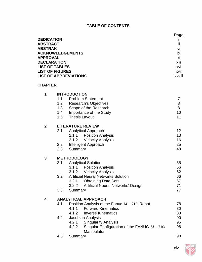
TABLE OF CONTENTS
Page DEDICATION ii ABSTRACT iii ABSTRAK vi ACKNOWLEDGEMENTS ix APPROVAL xi DECLARATION xiii LIST OF TABLES xvi LIST OF FIGURES xvii LIST OF ABBREVIATIONS xxviii CHAPTER
1 INTRODUCTION
1.1 Problem Statement 7 1.2 Research’s Objectives 8 1.3 Scope of the Research 8 1.4 Importance of the Study 10 1.5 Thesis Layout 11
2 LITERATURE REVIEW 2.1 Analytical Approach 12 2.1.1 Position Analysis 13 2.1.2 Velocity Analysis 16 2.2 Intelligent Approach 25 2.3 Summary 48
3 METHODOLOGY 3.1 Analytical Solution 55 3.1.1 Position Analysis 56 3.1.2 Velocity Analysis 62 3.2 Artificial Neural Networks Solution 66 3.2.1 Obtaining Data Sets 67 3.2.2 Artificial Neural Networks’ Design 71 3.3 Summary 77
4 ANALYTICAL APPROACH 4.1 Position Analysis of the Fanuc iM 710− Robot 78 4.1.1 Forward Kinematics 80 4.1.2 Inverse Kinematics 83 4.2 Jacobian Analysis 90 4.2.1 Singularity Analysis 95 4.2.2 Singular Configuration of the FANUC
Manipulator iM 710− 96
4.3 Summary 98
xiv
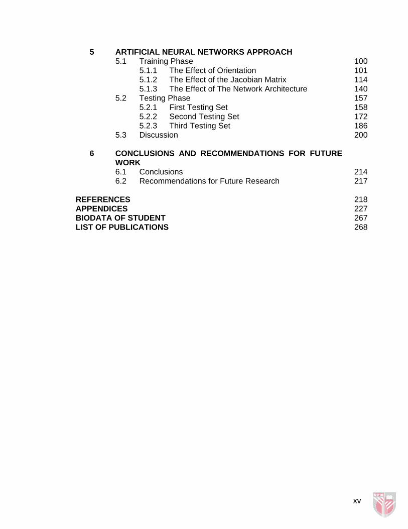
5 ARTIFICIAL NEURAL NETWORKS APPROACH 5.1 Training Phase 100 5.1.1 The Effect of Orientation 101 5.1.2 The Effect of the Jacobian Matrix 114 5.1.3 The Effect of The Network Architecture 140 5.2 Testing Phase 157 5.2.1 First Testing Set 158 5.2.2 Second Testing Set 172 5.2.3 Third Testing Set 186 5.3 Discussion
200
6 CONCLUSIONS AND RECOMMENDATIONS FOR FUTURE WORK
6.1 Conclusions 214 6.2 Recommendations for Future Research 217
REFERENCES 218 APPENDICES 227 BIODATA OF STUDENT 267 LIST OF PUBLICATIONS 268
xv
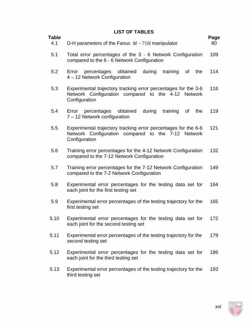
LIST OF TABLES Table Page
4.1 D-H parameters of the Fanuc iM 710− manipulator
80
5.1 Total error percentages of the 3 - 6 Network Configuration compared to the 6 - 6 Network Configuration
109
5.2 Error percentages obtained during training of the 4 – 12 Network Configuration
114
5.3 Experimental trajectory tracking error percentages for the 3-6 Network Configuration compared to the 4-12 Network Configuration
116
5.4 Error percentages obtained during training of the 7 – 12 Network configuration
119
5.5 Experimental trajectory tracking error percentages for the 6-6 Network Configuration compared to the 7-12 Network Configuration
121
5.6 Training error percentages for the 4-12 Network Configuration compared to the 7-12 Network Configuration
132
5.7 Training error percentages for the 7-12 Network Configuration compared to the 7-2 Network Configuration
149
5.8 Experimental error percentages for the testing data set for each joint for the first testing set
164
5.9 Experimental error percentages of the testing trajectory for the first testing set
165
5.10 Experimental error percentages for the testing data set for each joint for the second testing set
172
5.11 Experimental error percentages of the testing trajectory for the second testing set
179
5.12 Experimental error percentages for the testing data set for each joint for the third testing set
186
5.13 Experimental error percentages of the testing trajectory for the third testing set
193
xvi

LIST OF FIGURES Figure Page
1.1 The Fanuc Robot iM 710−
9
2.1 A schematic diagram of the implemented system by Köker et al. [36]
26
2.2 The kinematics model of the manipulator used by Köker et al. showing its direct kinematics equations
27
2.3 The two network configurations used by Hasan et al. [31]
28
2.4 The learning curve of Joint number 3 as a sample of the research done by Hasan et al. [31]
29
2.5 The network used in Bingul’s et al. study [34]
30
2.6 Learning curves for the three networks used by köker [29]
32
2.7 The two networks used in Karlik’s study [5]
34
2.8 The original network and its adjoint used in Kuroe’s study [35]
36
3.1 The general description of the adopted methodology
54
3.2 Analytical solution flow chart
55
3.3 Position analysis steps flow chart
56
3.4 Flow chart for the Artificial Neural Networks solution methodology
66
3.5 The Teach Pendent
70
3.6 Teach pendent screen shows how Cartesian position; orientation and joint angles are shown
70
3.7 Teach pendent screen shows how feed rates and position data are shows on the display screen
71
3.8 The Training Process
72
3.9 Training Stage I
74
3.10 Training Stage II
76
4.1 D-H Coordinate system for the Fanuc iM 710− Robot 79
xvii
4.2 Hand coordinate system and wrist coordinate system
84
4.3 Two different arm configurations corresponding to the two
solutions of 3θ
87
4.4 Screw coordinates with respect to an instantaneous reference frame for the Fanuc iM 710− robot
90
5.1 The architecture of the 3-6 Network Configuration
102
5.2 The learning curves for the 3-6 Network Configuration
103
5.3 The architecture of the 6-6 Network Configuration
104
5.4 Learning curves for the 6-6 Network Configuration
105
5.5 Learning curve of joint 1 for the 3-6 Network Configuration compared to the 6-6 Network Configuration
106
5.6 Learning curve of joint 2 for the 3-6 Network Configuration compared to the 6-6 Network Configuration
107
5.7 Learning curve of joint 3 for the 3-6 Network Configuration compared to the 6-6 Network Configuration
107
5.8 Learning curve of joint 4 for the 3-6 Network Configuration compared to the 6-6 Network Configuration
108
5.9 Learning curve of joint 5 for the 3-6 Network Configuration compared to the 6-6 Network Configuration
108
5.10 Learning curve of joint 6 for the 3-6 Network Configuration compared to the 6-6 Network Configuration
109
5.11 Angular position tracking of Joint 1 for the 3-6 Network Configuration compared to the 6-6 Network Configuration
110
5.12 Angular position tracking of Joint 2 for the 3-6 Network Configuration compared to the 6-6 Network Configuration
111
5.13 Angular position tracking of Joint 3 for the 3-6 Network Configuration compared to the 6-6 Network Configuration
111
5.14 Angular position tracking of Joint 4 for the 3-6 Network Configuration compared to the 6-6 Network Configuration
111
xviii
5.15 Angular position tracking of Joint 5 for the 3-6 Network Configuration compared to the 6-6 Network Configuration
112
5.16 Angular position tracking of Joint 6 for the 3-6 Network Configuration compared to the 6-6 Network Configuration
113
5.17 The architecture of the 4 – 12 Network Configuration
115
5.18 The learning curve for the 4 – 12 Network Configuration
115
5.19 Experimental Trajectory tracking of the X Coordinate for the 3-6 Network Configuration compared to the 4-12 Network Configuration
117
5.20 Experimental Trajectory tracking of the Y Coordinate for the 3-6 Network Configuration compared to the 4-12 Network Configuration
117
5.21 Experimental Trajectory tracking of the Z Coordinate for the 3-6 Network Configuration compared to the 4-12 Network Configuration
118
5.22 The architecture of the 7 – 12 Network Configuration
119
5.23 Learning curve for the 7 – 12 Network Configuration
120
5.24 Experimental trajectory tracking of the X Coordinate for the 6-6 Network Configuration compared to the 7-12 Network Configuration
122
5.25 Experimental trajectory tracking of the Y Coordinate for the 6-6 Network Configuration compared to the 7-12 Network Configuration
122
5.26 Experimental trajectory tracking of the Z Coordinate for the 6-6 Network Configuration compared to the 7-12 Network Configuration
123
5.27 Experimental trajectory tracking of the Roll orientation angle for the 6-6 Network Configuration compared to the 7-12 Network Configuration
123
5.28 Experimental trajectory tracking of the Pitch orientation angle for the 6-6 Network Configuration compared to the 7-12 Network Configuration
124
xix
5.29 Experimental trajectory tracking of the Yaw orientation angle for the 6-6 Network Configuration compared to the 7-12 Network Configuration
124
5.30 Learning curve of the angular position of joint 1 for the 4-12 Network Configuration compared to the 7-12 Network Configuration
125
5.31 Learning curve of the angular position of joint 2 for the 4-12 Network Configuration compared to the 7-12 Network Configuration
126
5.32 Learning curve of the angular position of joint 3 for the 4-12 Network Configuration compared to the 7-12 Network Configuration
126
5.33 Learning curve of the angular position of joint 4 for the 4-12 Network Configuration compared to the 7-12 Network Configuration
127
5.34 Learning curve of the angular position of joint 5 for the 4-12 Network Configuration compared to the 7-12 Network Configuration
127
5.35 Learning curve of the angular position of joint 6 for the 4-12 Network Configuration compared to the 7-12 Network Configuration
128
5.36 Learning curve of the angular velocity of joint 1 for the 4-12 Network Configuration compared to the 7-12 Network Configuration
128
5.37 Learning curve of the angular velocity of joint 2 for the 4-12 Network Configuration compared to the 7-12 Network Configuration
129
5.38 Learning curve of the angular velocity of joint 3 for the 4-12 Network Configuration compared to the 7-12 Network Configuration
129
5.39 Learning curve of the angular velocity of joint 4 for the 4-12 Network Configuration compared to the 7-12 Network Configuration
130
5.40 Learning curve of the angular velocity of joint 5 for the 4-12 Network Configuration compared to the 7-12 Network Configuration
130
xx

5.41 Learning curve of the angular velocity of joint 6 for the 4-12 Network Configuration compared to the 7-12 Network Configuration
131
5.42 Angular position tracking of joint 1 for the 7-12 Network Configuration compared to the 4-12 Network Configuration
133
5.43 Angular position tracking of joint 2 for the 7-12 Network Configuration compared to the 4-12 Network Configuration
134
5.44 Angular position tracking of joint 3 for the 7-12 Network Configuration compared to the 4-12 Network Configuration
134
5.45 Angular position tracking of joint 4 for the 7-12 Network Configuration compared to the 4-12 Network Configuration
135
5.46 Angular position tracking of joint 5 for the 7-12 Network Configuration compared to the 4-12 Network Configuration
135
5.47 Angular position tracking of joint 6 for the 7-12 Network Configuration compared to the 4-12 Network Configuration
136
5.48 Angular velocity tracking of joint 1 for the 7-12 Network Configuration compared to the 4-12 Network Configuration
136
5.49 Angular velocity tracking of joint 2 for the 7-12 Network Configuration compared to the 4-12 Network Configuration
137
5.50 Angular velocity tracking of joint 3 for the 7-12 Network Configuration compared to the 4-12 Network Configuration
137
5.51 Angular velocity tracking of joint 4 for the 7-12 Network Configuration compared to the 4-12 Network Configuration
138
5.52 Angular velocity tracking of joint 5 for the 7-12 Network Configuration compared to the 4-12 Network Configuration
138
5.53 Angular velocity tracking of joint 6 for the 7-12 Network Configuration compared to the 4-12 Network Configuration
139
5.54 The architecture of the 7 –2 Network Configuration
141
5.55 Learning curve of angular position of joint 1 for the 7-12 Network Configuration compared to the 7-2 Network Configuration
142
xxi
5.56 Learning curve of angular position of joint 2 for the 7-12 Network Configuration compared to the 7-2 Network Configuration
143
5.57 Learning curve of angular position of joint 3 for the 7-12 Network Configuration compared to the 7-2 Network Configuration
143
5.58 Learning curve of angular position of joint 4 for the 7-12 Network Configuration compared to the 7-2 Network Configuration
144
5.59 Learning curve of angular position of joint 5 for the 7-12 Network Configuration compared to the 7-2 Network Configuration
144
5.60 Learning curve of angular position of joint 6 for the 7-12 Network Configuration compared to the 7-2 Network Configuration
145
5.61 Learning curve of angular velocity of joint 1 for the 7-12 Network Configuration compared to the 7-2 Network Configuration
145
5.62 Learning curve of angular velocity of joint 2 for the 7-12 Network Configuration compared to the 7-2 Network Configuration
146
5.63 Learning curve of angular velocity of joint 3 for the 7-12 Network Configuration compared to the 7-2 Network Configuration
146
5.64 Learning curve of angular velocity of joint 4 for the 7-12 Network Configuration compared to the 7-2 Network Configuration
147
5.65 Learning curve of angular velocity of joint 5 for the 7-12 Network Configuration compared to the 7-2 Network Configuration
147
5.66 Learning curve of angular velocity of joint 6 for the 7-12 Network Configuration compared to the 7-2 Network Configuration
148
5.67 Angular position tracking of joint 1 for the 7-12 Network Configuration compared to the 7-2 Network Configuration
150
xxii
5.68 Angular position tracking of joint 2 for the 7-12 Network Configuration compared to the 7-2 Network Configuration
151
5.69 Angular position tracking of joint 3 for the 7-12 Network Configuration compared to the 7-2 Network Configuration
151
5.70 Angular position tracking of joint 4 for the 7-12 Network Configuration compared to the 7-2 Network Configuration
152
5.71 Angular position tracking of joint 5 for the 7-12 Network Configuration compared to the 7-2 Network Configuration
152
5.72 Angular position tracking of joint 6 for the 7-12 Network Configuration compared to the 7-2 Network Configuration
153
5.73 Angular velocity tracking of joint 1 for the 7-12 Network Configuration compared to the 7-2 Network Configuration
153
5.74 Angular velocity tracking of joint 2 for the 7-12 Network Configuration compared to the 7-2 Network Configuration
154
5.75 Angular velocity tracking of joint 3 for the 7-12 Network Configuration compared to the 7-2 Network Configuration
154
5.76 Angular velocity tracking of joint 4 for the 7-12 Network Configuration compared to the 7-2 Network Configuration
155
5.77 Angular velocity tracking of joint 5 for the 7-12 Network Configuration compared to the 7-2 Network Configuration
155
5.78 Angular velocity tracking of joint 6 for the 7-12 Network Configuration compared to the 7-2 Network Configuration
156
5.79 Predicted angular position experimental tracking of joint 1 for the first testing set
158
5.80 Predicted angular position experimental tracking of joint 2 for the first testing set
159
5.81 Predicted angular position experimental tracking of joint 3 for the first testing set
159
5.82 Predicted angular position experimental tracking of joint 4 for the first testing set
160
5.83 Predicted angular position experimental tracking of joint 5 for the first testing set
160
xxiii
5.84 Predicted angular position experimental tracking of joint 6 for the first testing set
161
5.85 Predicted angular velocity experimental tracking of joint 1 for the first testing set
161
5.86 Predicted angular velocity experimental tracking of joint 2 for the first testing set
162
5.87 Predicted angular velocity experimental tracking of joint 3 for the first testing set
162
5.88 Predicted angular velocity experimental tracking of joint 4 for the first testing set
163
5.89 Predicted angular velocity experimental tracking of joint 5 for the first testing set
163
5.90 Predicted angular velocity experimental tracking of joint 6 for the first testing set
164
5.91 Predicted trajectory tracking of X Coordinate for the first testing set
166
5.92 Predicted trajectory tracking of Y Coordinate for the first testing set
167
5.93 Predicted trajectory tracking of Z Coordinate for the first testing set
168
5.94 Predicted trajectory tracking of Roll orientation angle for the first testing set
169
5.95 Predicted trajectory tracking of Pitch orientation angle for the first testing set
170
5.96 Predicted trajectory tracking of Yaw orientation angle for the first testing set
171
5.97 Predicted angular position experimental tracking of joint 1 for the second testing set
173
5.98 Predicted angular position experimental tracking of joint 2 for the second testing set
173
5.99 Predicted angular position experimental tracking of joint 3 for the second testing set
174
xxiv