jabatan kejuruteraan elektrik pusat pengajian...
TRANSCRIPT
DDWK 3711 Electrical Machine
Experiments 2 : Three-phase Synchronous Generator
Update : May 2018 NDM Page 1
JABATAN KEJURUTERAAN ELEKTRIK PUSAT PENGAJIAN DIPLOMA (PPD), SPACE
UNIVERSITI TEKNOLOGI MALAYSIA KUALA LUMPUR
DDWK 3711
(ELECTRICAL MACHINE)
EXPERIMENT 2
THREE-PHASE SYNCHRONOUS GENERATOR
Sekolah Pendidikan Profesional dan Pendidikan Berterusan (SPACE)
DDWK 3711 Electrical Machine
Experiments 2 : Three-phase Synchronous Generator
Update : May 2018 NDM Page 2
Part 1: Measurement of the windings resistance
Objective ;
To calculate the winding resistance of asynchronous motor and generator with the Volt-Ampere
method (Ohm’s Law).
Theory ;
The motor windings resistance cause internal voltage drops that reduce their efficiency. Therefore
it must be as low as possible. It is calculated by applying DC voltages and measuring the resulting
current flows.
Formula:
PARAMETER SYMBOL UNIT
Winding Voltage V Volts
Winding Current I Amperes
Winding resistance R
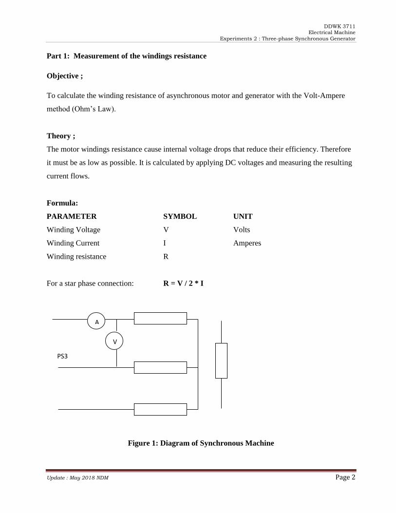
For a star phase connection: R = V / 2 * I
Figure 1: Diagram of Synchronous Machine
V
A
PS3
DDWK 3711 Electrical Machine
Experiments 2 : Three-phase Synchronous Generator
Update : May 2018 NDM Page 3
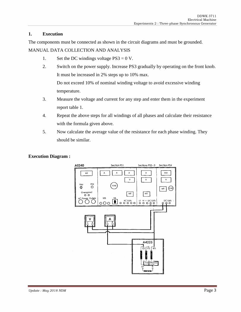
1. Execution
The components must be connected as shown in the circuit diagrams and must be grounded.
MANUAL DATA COLLECTION AND ANALYSIS
1. Set the DC windings voltage PS3 = 0 V.
2. Switch on the power supply. Increase PS3 gradually by operating on the front knob.
It must be increased in 2% steps up to 10% max.
Do not exceed 10% of nominal winding voltage to avoid excessive winding
temperature.
3. Measure the voltage and current for any step and enter them in the experiment
report table 1.
4. Repeat the above steps for all windings of all phases and calculate their resistance
with the formula given above.
5. Now calculate the average value of the resistance for each phase winding. They
should be similar.
Execution Diagram :
DDWK 3711 Electrical Machine
Experiments 2 : Three-phase Synchronous Generator
Update : May 2018 NDM Page 4
Part 2 : No Load Test
This experiment is performed on a SynchronousMachine.
Objective :
Plot the magnetization characteristics of a synchronous generator.
Theoretical review :
This experiment shows the characteristics of electromotive force Eo against the excitation/field
current Ie. The resulting graph shows that for the same value of excitation current there are two
different values of electromotive eforce, one for the ascendingand one for th descending curves.
Usually the medium value of Eo is considered.
The area enclosed in the magnetization loop represents the power losses for magnetic hysterisis
(residual magnetism)in the armature iron.
Formula :
PARAMETER SYMBOL UNIT
Voltage E01 Volts
ExcitationCurrent Ie Amperes
Pair of Poles p
Speed n1 rpm
Frequency F1 Hz
Theoretical Frequency f Hz
Theoretical Speed n rpm
Theoretical Voltage Eo Volts
Eo/Eo1 = n/n1
Eo = Eo1 * (n/n1) = Eo * (f/F1)
n = (60 * f)/p
DDWK 3711 Electrical Machine
Experiments 2 : Three-phase Synchronous Generator
Update : May 2018 NDM Page 5
Components :
Three Phase SynchronousMachine Model A4223
Squirrel Cage Three Phase Drive Motor Model A4220
Power Supply Model A0240
Paralleling Board Model A481 0
Cables Model A4890
Cables support Model A4891
Coupling Base Model A4840
Tachometer Model A4725
Ammeter With adequate range for this test
Voltmeter With adequate range for this tes
Frequency meter (F) Optional
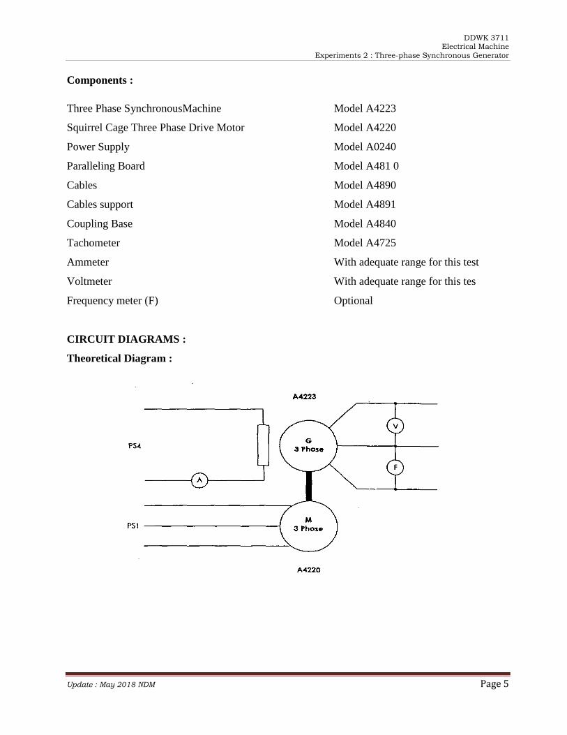
CIRCUIT DIAGRAMS :
Theoretical Diagram :
DDWK 3711 Electrical Machine
Experiments 2 : Three-phase Synchronous Generator
Update : May 2018 NDM Page 6
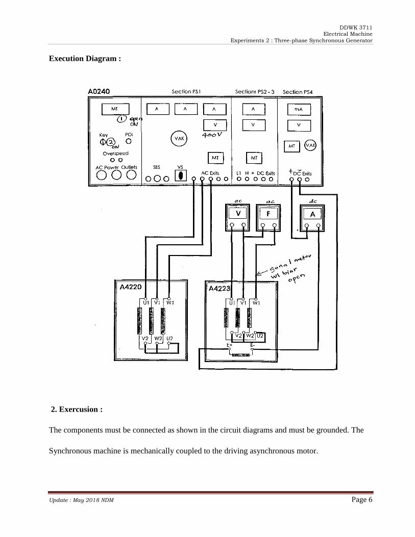
Execution Diagram :
2. Exercusion :
The components must be connected as shown in the circuit diagrams and must be grounded. The
Synchronous machine is mechanically coupled to the driving asynchronous motor.
DDWK 3711 Electrical Machine
Experiments 2 : Three-phase Synchronous Generator
Update : May 2018 NDM Page 7
Manual Data Collection And Analysis :
1. Set the excitation voltage PS4 and drive motor voltage PS1=O.
2. Switch on the power supply and adjust Psi to nominal motor voltage (400 V). When
the motor is up to speed gradually increase the excitation voltage from 20 V to 120 V
in 10 V steps (shown in Table2 in the report sheet).
3. At each step enter in the worksheet Table 2 the values of the excitation current Ie,
Voltage E01 and frequency F1.
4. Plot the graph of voltage Eo, versus excitation current Ie. Maximum Ie = 0.2 A.
Part 3 : Short Circuit Test
This experiment is performed on a Synchronous Machine.
Objective :
Plot the short circuit characteristics of a synchronous generator. The short circuit diagram shows
the output current versus the excitation current when the armature windings are short circuited.
Theory :
This test is performed by driving the generator to a speed close to nominal and by measuring the
Short circuit current while stepping up the excitation current. It is not necessary to measure the
output frequency as the short circuit current is largely independent from speed when the qenerator
is running close to nominal RPM.
DDWK 3711 Electrical Machine
Experiments 2 : Three-phase Synchronous Generator
Update : May 2018 NDM Page 8
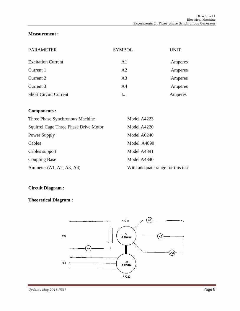
Measurement :
PARAMETER SYMBOL UNIT
Excitation Current A1 Amperes
Current 1 A2 Amperes
Current 2 A3 Amperes
Current 3 A4 Amperes
Short Circuit Current Isc Amperes
Components :
Three Phase Synchronous Machine Model A4223
Squirrel Cage Three Phase Drive Motor Model A4220
Power Supply Model A0240
Cables Model A4890
Cables support Model A4891
Coupling Base Model A4840
Ammeter (A1, A2, A3, A4) With adequate range for this test
Circuit Diagram :
Theoretical Diagram :
DDWK 3711 Electrical Machine
Experiments 2 : Three-phase Synchronous Generator
Update : May 2018 NDM Page 9
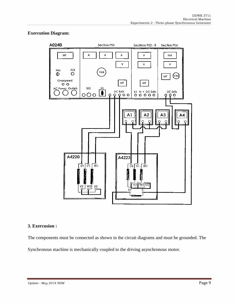
Exercution Diagram:
3. Exercusion :
The components must be connected as shown in the circuit diagrams and must be grounded. The
Synchronous machine is mechanically coupled to the driving asynchronous motor.
DDWK 3711 Electrical Machine
Experiments 2 : Three-phase Synchronous Generator
Update : May 2018 NDM Page 10
Manual Data Collection and Analysis :
1. Set the excitation voltage PS4 and motor supply voltage PS1=O.
2. Switch on the power supply. Start the driving motor.
3. When the motor reaches nominal speed, step up the excitation current Ie until
nominal current is reached.
4. At each step enter in Table 3 in the report sheet the values of the excitation and
generator currents.
5. Calculate the short circuit current as the average of the generator currents.
6. Plot the graph lsc versus Ie.
Maximum lsc = 1.3 A
Maximum Ie,= 0.2 A
Notes: Since the short circuit test is linear, it can be drawn by measuring only two points.
DDWK 3711 Electrical Machine
Report Sheet 1 Three Phase Transformer
Update: May 2018 NDM Page 1
JABATAN KEJURUTERAAN ELEKTRIK PUSAT PENGAJIAN DIPLOMA (PPD), SPACE
UNIVERSITI TEKNOLOGI MALAYSIA KUALA LUMPUR
DDWK 3711 (ELECTRICAL MACHINE)
REPORT SHEET
EXPERIMENT 2: THREE PHASE SYNCHRONOUS GENERATOR
Group members 1.
2.
3.
4.
5.
Lecturer :
Date :
No. PLO CLO Student Marks Marks
1 PLO1 CLO6 40
2 PLO2 CLO6 50
3 PLO8 CLO6 10
Total Marks /100
UTM
UNIVERSITI
TEKNOLOGI MALAYSIA
Sekolah Pendidikan Profesional dan Pendidikan Berterusan (SPACE)
DDWK 3711 Electrical Machine
Report Sheet 1 Three Phase Transformer
Update: May 2018 NDM Page 2
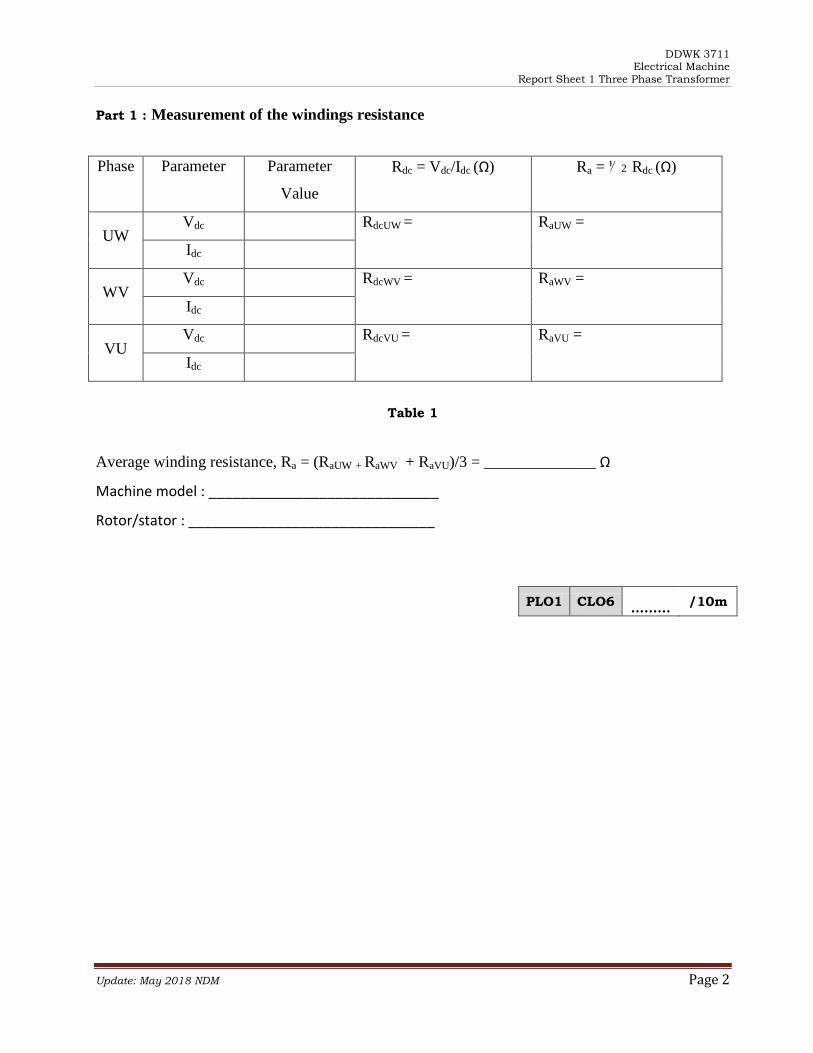
Part 1 : Measurement of the windings resistance
Phase Parameter Parameter
Value
Rdc = Vdc/Idc (Ω) Ra = ⅟ 2 Rdc (Ω)
UW Vdc RdcUW = RaUW =
Idc
WV Vdc RdcWV = RaWV =
Idc
VU Vdc RdcVU = RaVU =
Idc
Table 1
Average winding resistance, Ra = (RaUW + RaWV + RaVU)/3 = ______________ Ω
Machine model : _____________________________
Rotor/stator : _______________________________
PLO1 CLO6 ………
/10m
DDWK 3711 Electrical Machine
Report Sheet 1 Three Phase Transformer
Update: May 2018 NDM Page 3
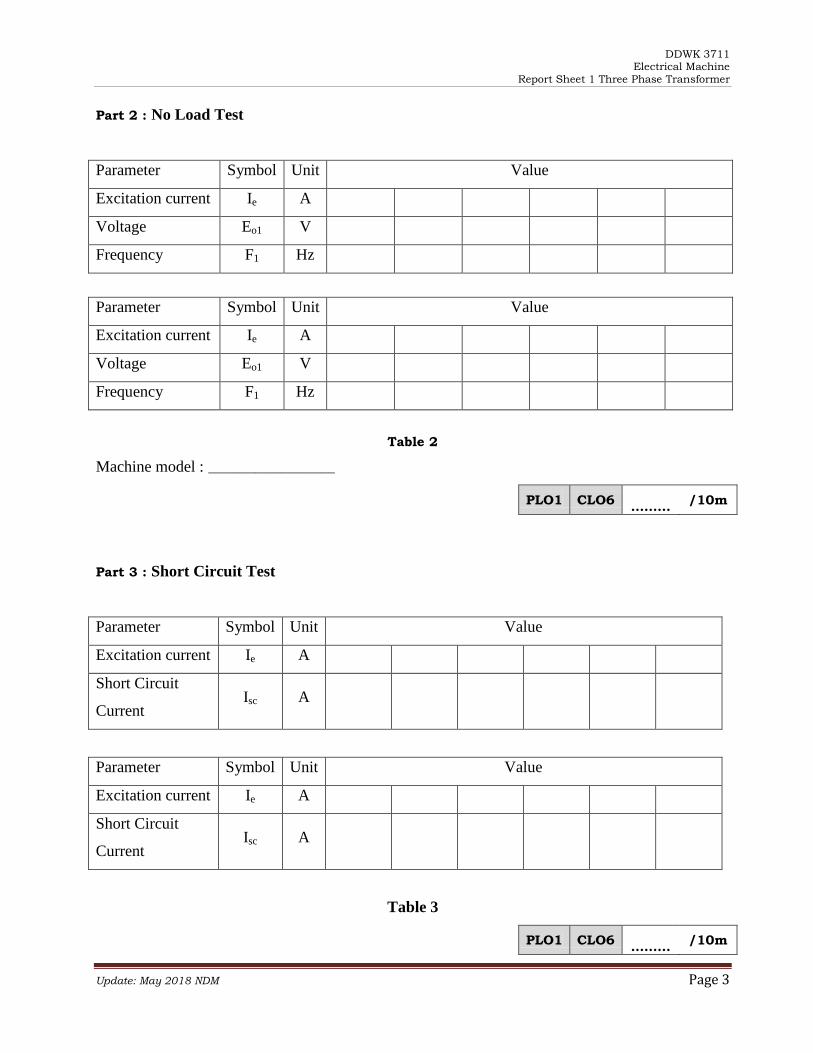
Part 2 : No Load Test
Parameter Symbol Unit Value
Excitation current Ie A
Voltage Eo1 V
Frequency F1 Hz
Parameter Symbol Unit Value
Excitation current Ie A
Voltage Eo1 V
Frequency F1 Hz
Table 2
Machine model : ___________________
PLO1 CLO6 ………
/10m
Part 3 : Short Circuit Test
Parameter Symbol Unit Value
Excitation current Ie A
Short Circuit
Current Isc A
Parameter Symbol Unit Value
Excitation current Ie A
Short Circuit
Current Isc A
Table 3
PLO1 CLO6 ………
/10m
DDWK 3711 Electrical Machine
Report Sheet 1 Three Phase Transformer
Update: May 2018 NDM Page 4
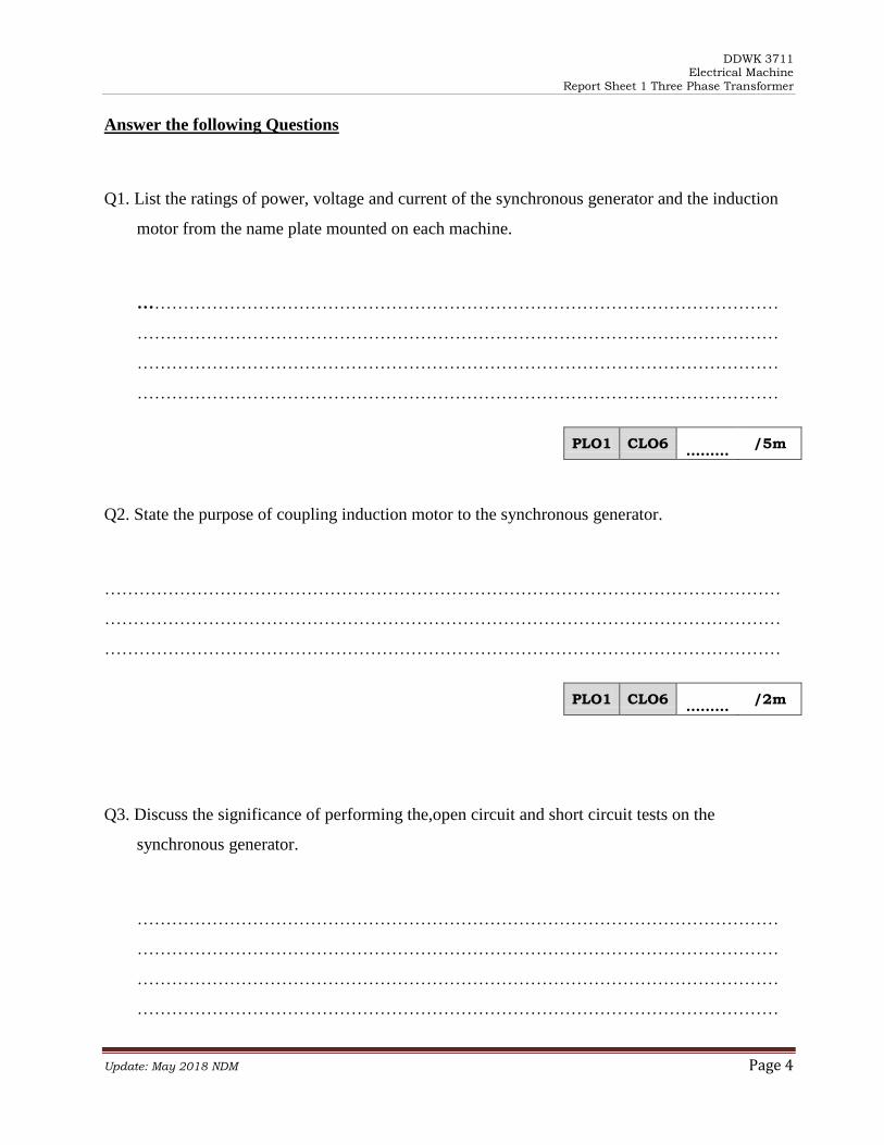
Answer the following Questions
Q1. List the ratings of power, voltage and current of the synchronous generator and the induction
motor from the name plate mounted on each machine.
…………………………………………………………………………………………………
…………………………………………………………………………………………………
…………………………………………………………………………………………………
…………………………………………………………………………………………………
PLO1 CLO6 ………
/5m
Q2. State the purpose of coupling induction motor to the synchronous generator.
………………………………………………………………………………………………………
………………………………………………………………………………………………………
………………………………………………………………………………………………………
PLO1 CLO6 ………
/2m
Q3. Discuss the significance of performing the,open circuit and short circuit tests on the
synchronous generator.
…………………………………………………………………………………………………
…………………………………………………………………………………………………
…………………………………………………………………………………………………
…………………………………………………………………………………………………
DDWK 3711 Electrical Machine
Report Sheet 1 Three Phase Transformer
Update: May 2018 NDM Page 5
…………………………………………………………………………………………………
…………………………………………………………………………………………………
…………………………………………………………………………………………………
PLO1 CLO6 ………
/6m
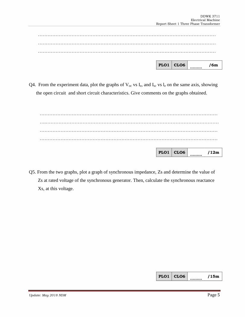
Q4. From the experiment data, plot the graphs of Voc vs Ie, and Isc vs le on the same axis, showing
the open circuit and short circuit characteristics. Give comments on the graphs obtained.
…………………………………………………………………………………………………
….………………………………………………………………………………………………
…………………………………………………………………………………………………
…………………………………………………………………………………………………
PLO1 CLO6 ………
/12m
Q5. From the two graphs, plot a graph of synchronous impedance, Zs and determine the value of
Zs at rated voltage of the synchronous generator. Then, calculate the synchronous reactance
Xs, at this voltage.
PLO1 CLO6 ………
/15m
DDWK 3711 Electrical Machine
Report Sheet 1 Three Phase Transformer
Update: May 2018 NDM Page 6
Q6. Write the conclusion of the experiment.
………………………………………………………………………………………………
………………………………………………………………………………………………
………………………………………………………………………………………………
………………………………………………………………………………………………
………………………………………………………………………………………………
………………………………………………………………………………………………
………………………………………………………………………………………………
PLO1 CLO6 ………
/10m