abstract - eprints.utm.myeprints.utm.my/id/eprint/9536/7/jhonnymfksg2010.pdf · ini adalah untuk...
TRANSCRIPT
v
ABSTRACT
Sundaland, which covers Peninsular Malaysia, Sumatra, Java, Borneo, Thailand,
Myanmar, Cambodia, Laos and Vietnam, has moved towards the east before the Aceh
earthquake, but shortly after the earthquake, the motion of most of Sundaland was
towards the west. The main objective of this study is to monitor the post-seismic motion
of Peninsular Malaysia due to the previous earthquakes such as Aceh 2004, Nias 2005
and Bengkulu 2007. Seventy eight (78) Malaysia Real Time Kinematic Network
(MyRTKnet) and thirty (30) Global Positioning System (GPS) stations worldwide were
used in this study. The Bernese 5.0 software with double difference strategy was used to
process all the data. The results show that the west-northwest part has the worse
deformation in comparison to the other parts. Generally, from 2004 until 2005
Peninsular Malaysia moved towards west-southwest by 8.2 cm per year but in 2006,
there was a slight change in the motion. From 2006 until 2008, the southern part has
moved towards east-southeast by 0.23 cm per year and the northern part moved towards
west-southwest by 5.9 cm per year. These motions have caused different displacements
between both northern and southern parts, and may have triggered local faults
movement. The other objective of this study is to identify whether the Raub-Bentong
suture had any seismic activity. In 2007 until 2009, several tremors were recorded in
Bukit Tinggi, Kuala Pilah, and Jerantut areas. These tremors are believed as indications
of fault movement in Bukit Tinggi, Kuala Lumpur or Raub-Bentong. The determination
of fault movement in this study was based on selected MyRTKnet baselines analysis.
The technique is unable to identify the fault movement due to the fact that MyRTKnet
stations are sparse and are far away from the fault lines. Therefore, it is necessary to
carry out GPS field campaign along Bukit Tinggi and Kuala Lumpur faults in the future.
Besides that, continuous post-seismic monitoring is needed to get a better picture of the
seismic cycle in Peninsular Malaysia.
vi
ABSTRAK
Sundaland yang meliputi Semenanjung Malaysia, Sumatra, Jawa, Kalimantan, Thailand, Myanmar, Kemboja, Laos dan Vietnam telah bergerak ke arah timur sebelum gempa bumi Aceh, tetapi tidak lama selepas gempa, pergerakan sebahagian besar daripada Sundaland adalah ke arah barat. Objektif utama kajian ini adalah untuk memantau pergerakan pasca-sesmik bagi Semenanjung Malaysia terhadap gempa bumi terdahulu iaitu Aceh 2004, Nias 2005 dan Bengkulu 2007. Tujuh puluh lapan (78) Malaysia Real Time Kinematic Network (MyRTKnet) dan tiga puluh (30) stesyen Sistem Penentuan Sejagat (GPS) bagi seluruh dunia digunakan dalam kajian ini. Perisian Bernese 5.0 dengan strategi perbezaan ganda dua telah digunakan untuk memproses semua data. Keputusan pemprosesan menunjukkan bahawa bahagian barat-barat laut Semenanjung Malaysia telah mengalami deformasi yang paling ketara berbanding dengan bahagian lain. Secara umum, dari tahun 2004 hingga 2005 Semenanjung Malaysia telah bergerak ke arah barat-barat daya sebanyak 8.2 cm setahun tetapi pada tahun 2006, terdapat sedikit perubahan dalam pergerakannya. Dari tahun 2006 hingga 2008, bahagian selatan telah bergerak ke arah timur-tenggara sebanyak 0.23 cm setahun dan bahagian utara telah bergerak ke arah barat-barat daya sebanyak 5.9 cm setahun. Gerakan ini telah menyebabkan anjakan berbeza di antara kedua-dua bahagian utara dan selatan, dan kemungkinan mencetuskan pergerakan sesar tempatan. Objektif lain kajian ini adalah untuk mengenalpasti samada jahitan Raub-Bentong mempunyai aktiviti sesmik. Pada tahun 2007 hingga 2009, beberapa gegaran telah direkodkan di kawasan Bukit Tinggi, Kuala Pilah, dan Jerantut. Gegaran ini dipercayai sebagai petanda gerakan sesar di Bukit Tinggi, Kuala Lumpur atau Raub-Bentong. Penentuan pergerakan sesar di dalam kajian ini adalah berdasarkan analisis garis dasar MyRTKnet yang terpilih. Teknik tersebut tidak boleh mengenalpasti pergerakan sesar disebabkan fakta yang menunjukkan stesyen MyRTKnet adalah jarang dan jauh daripada garisan sesar. Oleh yang demikian, ia adalah perlu untuk melaksanakan kempen kerjaluar GPS di sepanjang sesar Bukit Tinggi dan Kuala Lumpur pada masa hadapan. Selain itu, pemantauan pasca-sesmik secara berterusan diperlukan untuk mendapatkan gambaran putaran sesmik yang lebih baik di Semenanjung Malaysia.

vii
TABLE OF CONTENTS
CHAPTER TITLE PAGE
DECLARATION ii
DEDICATION iii
ACKNOWLEDGEMENTS iv
ABSTRACT v
ABSTRAK vi
TABLE OF CONTENTS vii
LIST OF TABLES x
LIST OF FIGURES xii
LIST OF ABBREVIATIONS xvi
LIST OF SYMBOLS xviii
LIST OF APPENDICES xix
1 INTRODUCTION 1
1.1 Introduction 1
1.2 Problem Statement 2
1.3 Research Objective 4
1.4 Research Scope 4
1.5 Research Contribution 5
1.6 Study Area 5
1.7 Research Methodology 6
1.8 Chapter Content 8
viii
2 PLATE TECTONIC, EARTHQUAKE AND TECTONIC
SETTING OF PENINSULAR MALAYSIA
9
2.1 Plate Tectonic 9
2.1.1 Subduction 11
2.1.2 Transform Fault 11
2.1.3 Paleomagnetism and Motion of the Plates 12
2.1.4 Wilson Cycle 13
2.2 Earthquake 14
2.2.1 Cause of Earthquake 15
2.2.2 Measurement of Earthquake 16
2.3 Tectonic Setting of Peninsular Malaysia 20
2.3.1 Faults Distribution in Peninsular Malaysia 22
2.3.1.1 Bentong-Raub Suture 26
2.3.1.2 Lebir Fault Zone 27
2.3.1.3 Kuala Lumpur Fault Zone 28
2.3.1.4 Bukit Tinggi Fault Zone 28
2.3.1.5 Bok Bak Fault Zone 28
2.3.1.6 Lepar Fault Zone 29
2.3.1.7 Mersing-Endau Fault Zone 29
3 GLOBAL AND LOCAL GNSS INFRASTUCTURES
AND APPLICATION ON GEODYNAMIC
30
3.1 Global GNSS Infrastructure 30
3.2 Malaysia GNSS Infrastructure 33
3.2.1 Malaysia Active GPS System (MASS) 33
3.2.2 Malaysia Real Time Kinematic GNSS Network
(MyRTKnet)
36
3.3 GPS Application for Geodynamic 37
3.3.1 GPS for Earthquake Detection 38
3.3.2 GPS for Fault Monitoring 39
ix
4 DATA COLLECTION AND PROCESSING STRATEGY 42
4.1 Data Collection 42
4.2 Processing Strategy 46
4.2.1 Bernese Structure 47
4.2.2 GPS Data Quality Control 50
4.2.3 Mapping Solution into ITRF 2005 51
5 RESULTS AND ANALYSIS OF SEISMIC MOTION IN
PENINSULAR MALAYSIA
52
5.1 Pre-Seismic Motion 53
5.2 Co-Seismic Motion 54
5.2.1 Co-Seismic due to Aceh Earthquake 55
5.2.2 Co-Seismic due to Nias Earthquake 59
5.2.3 Co-Seismic of earthquake occurred later than
2005
62
5.3 Post-Seismic motion 65
5.4 Seismic Modeling 70
5.5 Seismic Interpretation 73
6 RESULTS AND ANALYSIS OF FAULT MOVEMENT 77
6.1 Network Design 78
6.2 Fault Network Processing Strategy 79
6.3 Fault Analysis 82
7 CONCLUSION AND RECOMMENDATIONS 87
7.1 Conclusion 87
7.2 Recommendations 89
REFERENCES 90
APPENDIXES 95
x
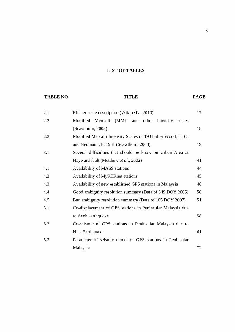
LIST OF TABLES
TABLE NO TITLE PAGE
2.1 Richter scale description (Wikipedia, 2010) 17
2.2 Modified Mercalli (MMI) and other intensity scales
(Scawthorn, 2003)
18
2.3 Modified Mercalli Intensity Scales of 1931 after Wood, H. O.
and Neumann, F, 1931 (Scawthorn, 2003)
19
3.1 Several difficulties that should be know on Urban Area at
Hayward fault (Metthew et al., 2002)
41
4.1 Availability of MASS stations 44
4.2 Availability of MyRTKnet stations 45
4.3 Availability of new established GPS stations in Malaysia 46
4.4 Good ambiguity resolution summary (Data of 349 DOY 2005) 50
4.5 Bad ambiguity resolution summary (Data of 105 DOY 2007) 51
5.1 Co-displacement of GPS stations in Peninsular Malaysia due
to Aceh earthquake
58
5.2 Co-seismic of GPS stations in Peninsular Malaysia due to
Nias Earthquake
61
5.3 Parameter of seismic model of GPS stations in Peninsular
Malaysia
72

xi
6.1 Approximate distance between GPS station to Raub-Bentong
Suture
79
6.2 Ambiguity summaries for fault monitoring campaign 81
6.3 The baseline length of each station to GRIK station 83
6.4 The baseline length of each station to TLOH station 86
xii
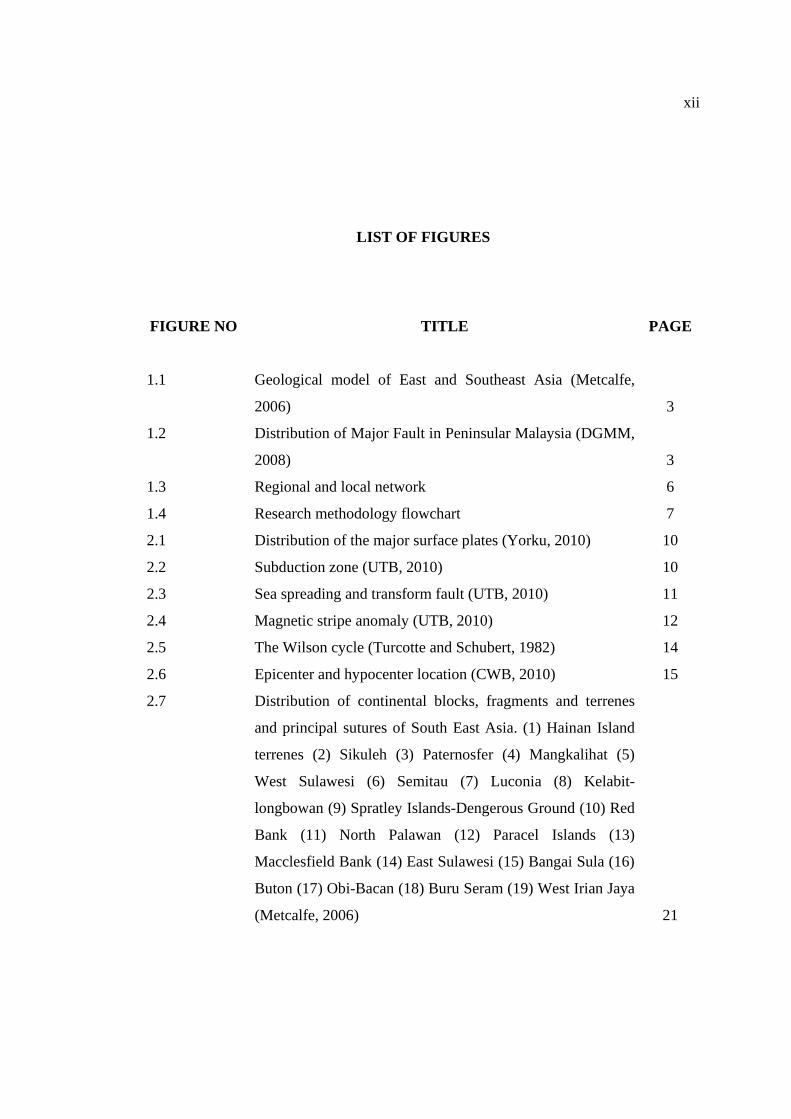
LIST OF FIGURES
FIGURE NO TITLE PAGE
1.1 Geological model of East and Southeast Asia (Metcalfe,
2006)
3
1.2 Distribution of Major Fault in Peninsular Malaysia (DGMM,
2008)
3
1.3 Regional and local network 6
1.4 Research methodology flowchart 7
2.1 Distribution of the major surface plates (Yorku, 2010) 10
2.2 Subduction zone (UTB, 2010) 10
2.3 Sea spreading and transform fault (UTB, 2010) 11
2.4 Magnetic stripe anomaly (UTB, 2010) 12
2.5 The Wilson cycle (Turcotte and Schubert, 1982) 14
2.6 Epicenter and hypocenter location (CWB, 2010) 15
2.7 Distribution of continental blocks, fragments and terrenes
and principal sutures of South East Asia. (1) Hainan Island
terrenes (2) Sikuleh (3) Paternosfer (4) Mangkalihat (5)
West Sulawesi (6) Semitau (7) Luconia (8) Kelabit-
longbowan (9) Spratley Islands-Dengerous Ground (10) Red
Bank (11) North Palawan (12) Paracel Islands (13)
Macclesfield Bank (14) East Sulawesi (15) Bangai Sula (16)
Buton (17) Obi-Bacan (18) Buru Seram (19) West Irian Jaya
(Metcalfe, 2006)
21
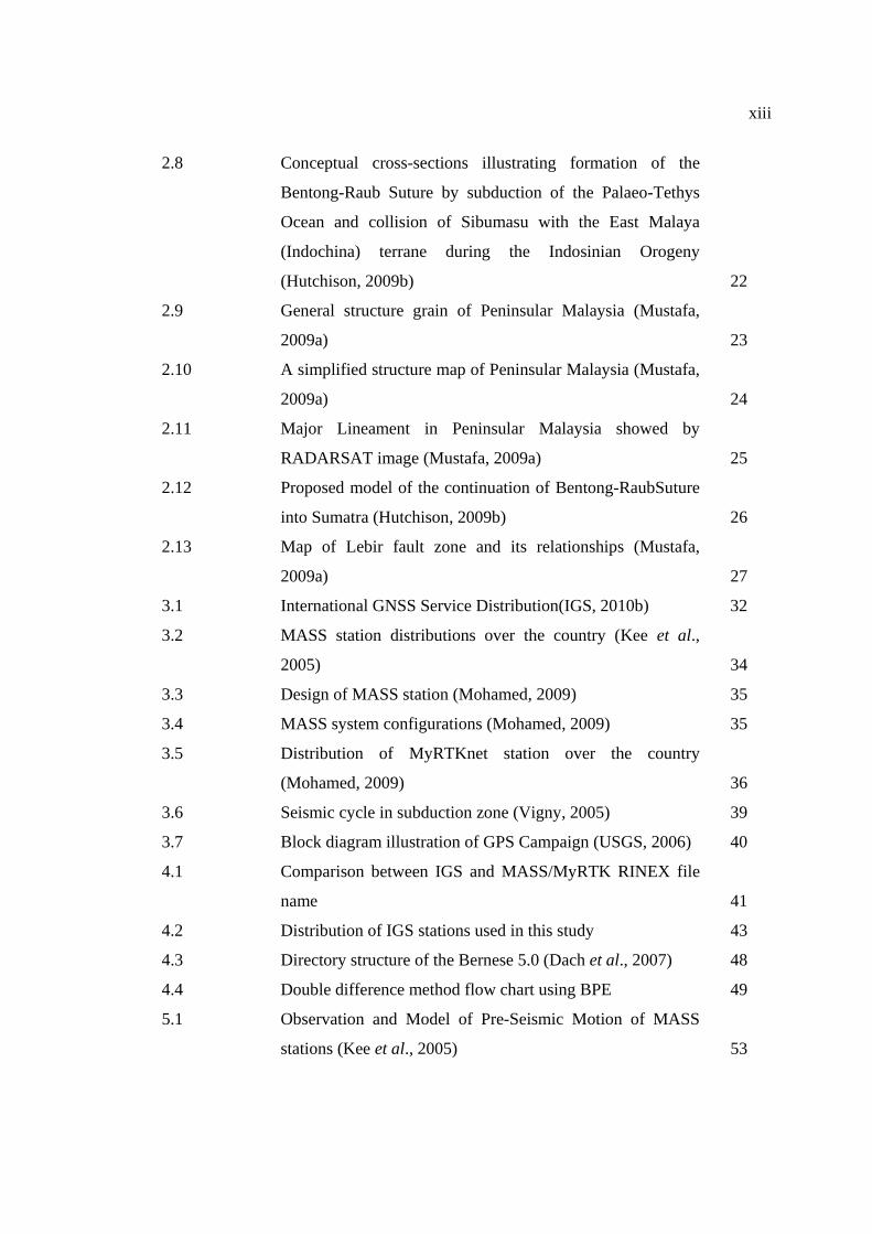
xiii
2.8 Conceptual cross-sections illustrating formation of the
Bentong-Raub Suture by subduction of the Palaeo-Tethys
Ocean and collision of Sibumasu with the East Malaya
(Indochina) terrane during the Indosinian Orogeny
(Hutchison, 2009b)
22
2.9 General structure grain of Peninsular Malaysia (Mustafa,
2009a)
23
2.10 A simplified structure map of Peninsular Malaysia (Mustafa,
2009a)
24
2.11 Major Lineament in Peninsular Malaysia showed by
RADARSAT image (Mustafa, 2009a)
25
2.12 Proposed model of the continuation of Bentong-RaubSuture
into Sumatra (Hutchison, 2009b)
26
2.13 Map of Lebir fault zone and its relationships (Mustafa,
2009a)
27
3.1 International GNSS Service Distribution(IGS, 2010b) 32
3.2 MASS station distributions over the country (Kee et al.,
2005)
34
3.3 Design of MASS station (Mohamed, 2009) 35
3.4 MASS system configurations (Mohamed, 2009) 35
3.5 Distribution of MyRTKnet station over the country
(Mohamed, 2009)
36
3.6 Seismic cycle in subduction zone (Vigny, 2005) 39
3.7 Block diagram illustration of GPS Campaign (USGS, 2006) 40
4.1 Comparison between IGS and MASS/MyRTK RINEX file
name
41
4.2 Distribution of IGS stations used in this study 43
4.3 Directory structure of the Bernese 5.0 (Dach et al., 2007) 48
4.4 Double difference method flow chart using BPE 49
5.1 Observation and Model of Pre-Seismic Motion of MASS
stations (Kee et al., 2005)
53
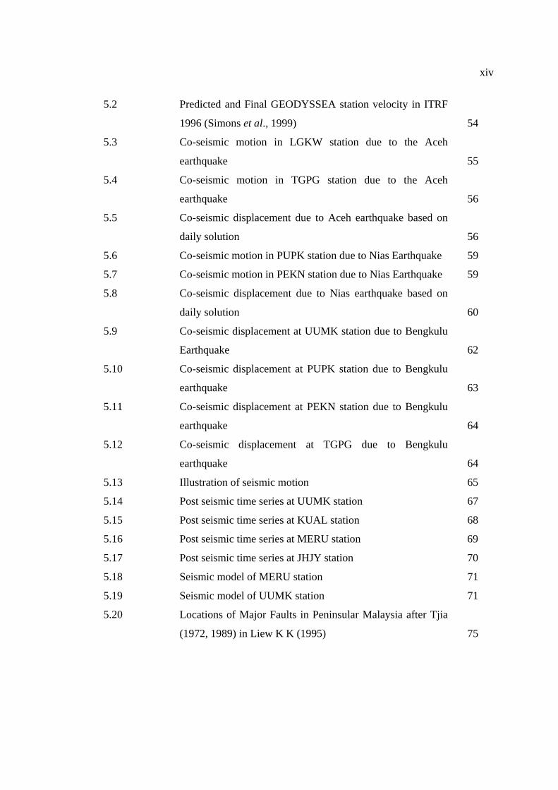
xiv
5.2 Predicted and Final GEODYSSEA station velocity in ITRF
1996 (Simons et al., 1999)
54
5.3 Co-seismic motion in LGKW station due to the Aceh
earthquake
55
5.4 Co-seismic motion in TGPG station due to the Aceh
earthquake
56
5.5 Co-seismic displacement due to Aceh earthquake based on
daily solution
56
5.6 Co-seismic motion in PUPK station due to Nias Earthquake 59
5.7 Co-seismic motion in PEKN station due to Nias Earthquake 59
5.8 Co-seismic displacement due to Nias earthquake based on
daily solution
60
5.9 Co-seismic displacement at UUMK station due to Bengkulu
Earthquake
62
5.10 Co-seismic displacement at PUPK station due to Bengkulu
earthquake
63
5.11 Co-seismic displacement at PEKN station due to Bengkulu
earthquake
64
5.12 Co-seismic displacement at TGPG due to Bengkulu
earthquake
64
5.13 Illustration of seismic motion 65
5.14 Post seismic time series at UUMK station 67
5.15 Post seismic time series at KUAL station 68
5.16 Post seismic time series at MERU station 69
5.17 Post seismic time series at JHJY station 70
5.18 Seismic model of MERU station 71
5.19 Seismic model of UUMK station 71
5.20 Locations of Major Faults in Peninsular Malaysia after Tjia
(1972, 1989) in Liew K K (1995)
75
xv
5.21 Tremor epicenter distribution of Bukit Tinggi, Kuala Pilah
and Jerantut from 2007 - 2009 (Meteorological Department
Malaysia, 2010)
76
6.1 GPS network design for Raub-Bentong suture 78
6.2 IGS stations distribution used in fault network 80
6.3 The baseline residual in the north and the east from time to
time respected to GRIK station
82
6.4 Displacement vector of UPMS, TLOH, JUIP, GMUS and
RTPJ stations respectively to GRIK station (session V – VII)
84
6.5 The baseline residual in the north and the east from time to
time respected to TLOH station
85
6.6 Displacement vector of UPMS, JUIP, GRIK, GMUS and
RTPJ stations respectively to TLOH station (session V –
VII)
85
xvi
LIST OF ABBREVIATIONS
AS : Anti Spoofing
BPE : Bernese Processing Engine
CZH : Code Zero Header
CZO : Code Zero Observation
DGPS : Differential Global Positioning System
DGMM : Department Geoscience and Mineral Malaysia
DSMM : Department Survey and Mapping Malaysia
ESE : East-Southeast
GEODYSSEA : Geodynamic South and South East Asia
GLONASS : The Global Navigation Satellite System
GMT : Generic Mapping Tool
GNSS : Global Navigation Satellite System
GPS : Global Positioning System
IGS : International GNSS Services for Geodynamic
ITRF : International Terrestrial Reference Frame
MASS : Malaysia Active GPS System
MMD : Malaysia Meteorology Department
MMI : Modified Mercalli Intensity
MyRTKnet : Malaysia Real Time Kinematic GNSS Network
N : North
NAVSAT : Navy Navigation Satellite System
NAVSTAR : Navigation Satellite Timing and Ranging
NNW : North-Northwest
NW : Northwest
PPP : Precise Point Positioning

xvii
PZH : Phase Zero Header
PZO : Phase Zero Observation
QIF : Quasi Ionosphere Free
RINEX : Receiver Independent Exchange
RMS : Root Mean Square
S : South
SA : Selective Availability
SE : Southeast
SEAMERGES : South East Asia Mastering Environmental Research with
Geodetic Space Technique
SSE : South-Southeast
USGS : United States Geological Survey
UTC : Universal Time Coordinate
VRS : Virtual Reference Station
WNW : West-Northwest

xviii
LIST OF SYMBOLS
a - Amplitude associated with the decay (mm)
Ao - A standard value as a function of distance
At - Maximum trace amplitude
b - Constant amplitude (mm)
ΔX1; ΔX2; ΔXn - Co-seismic displacement (constant parameter)
ML - Local magnitude
Po1(t); Po2(t); Pon(t); Post(t) - Post-seismic displacement
t - Time of any desire epoch
t0 - Time of reference epoch
u - Mean relative displacement
V - Velocity
X(t) - Position at time t
X0 - Position at time t0

xix
LIST OF APPENDICES
APPENDIX TITLE PAGE
A Co Seismic time series due to Aceh earthquake 95
B Co Seismic time series due to Nias earthquake 106
C Post Seismic time series from 2004 until 2008 118
D Station motion from 2004 until 2008 130
E Total displacement from 2004 until 2008 141
CHAPTER 1
INTRODUCTION 1.1 Introduction
In the last few decades, geoscientists have used polar magnetic to explain plate
movements; thereby making plate tectonic concepts acceptable by the geosciences
community. The advent of the space technique in the 1970s has led to the development
and global acceptance of the Global Positioning System (GPS) technology. This new
technique has evolved into spatiality in the studying of geodynamics. In 1994 there was
a project known as GEODYSSEA (Geodynamic South and South East Asia). The aim of
this project was to study the plate motion and crustal deformation in the region of South
and South East Asia (S.E.A). The result of that project showed that Sundaland block
which covered Peninsular Malaysia, Sumatra, Java, Borneo, Thailand, Myanmar,
Cambodia, Laos and Vietnam has a distinct relative motion with respect to the stable
part of the Eurasian Plate (Simon et al., 1999).
Few years after GEODYSSEA was completed, there were two big earthquakes,
which devastated the Sundaland block. The first one occurred near the Aceh region,
North of Sumatra with the epicenter 3.316oN, 95.845oE and depth about 30 kilometers
with 9.1 Mw (USGS, 2004) on 26 December 2004. The second earthquake occurred
with the epicenter 2.0740N, 97.013oE and depth about 30 kilometers with 8.6 Mw
(USGS, 2005) hit the Nias region, North of Sumatra on 28 March, 2005. The first
earthquake caused a deformation of an area over 4000 kilometers from the epicenter.
2
The largest co-seismic displacement reached to about 400 kilometers away from the
epicenter (Vigny et al., 2005). The Nias earthquake also caused deformation but was not
as widespread as the first Aceh earthquake. Kee et al. (2005) observed that, the shape of
Peninsular Malaysia has deformed into an irregular form. However, this occurrence may
vary from time to time and it could become an interesting issue for future investigation.
1.2 Problem Statement
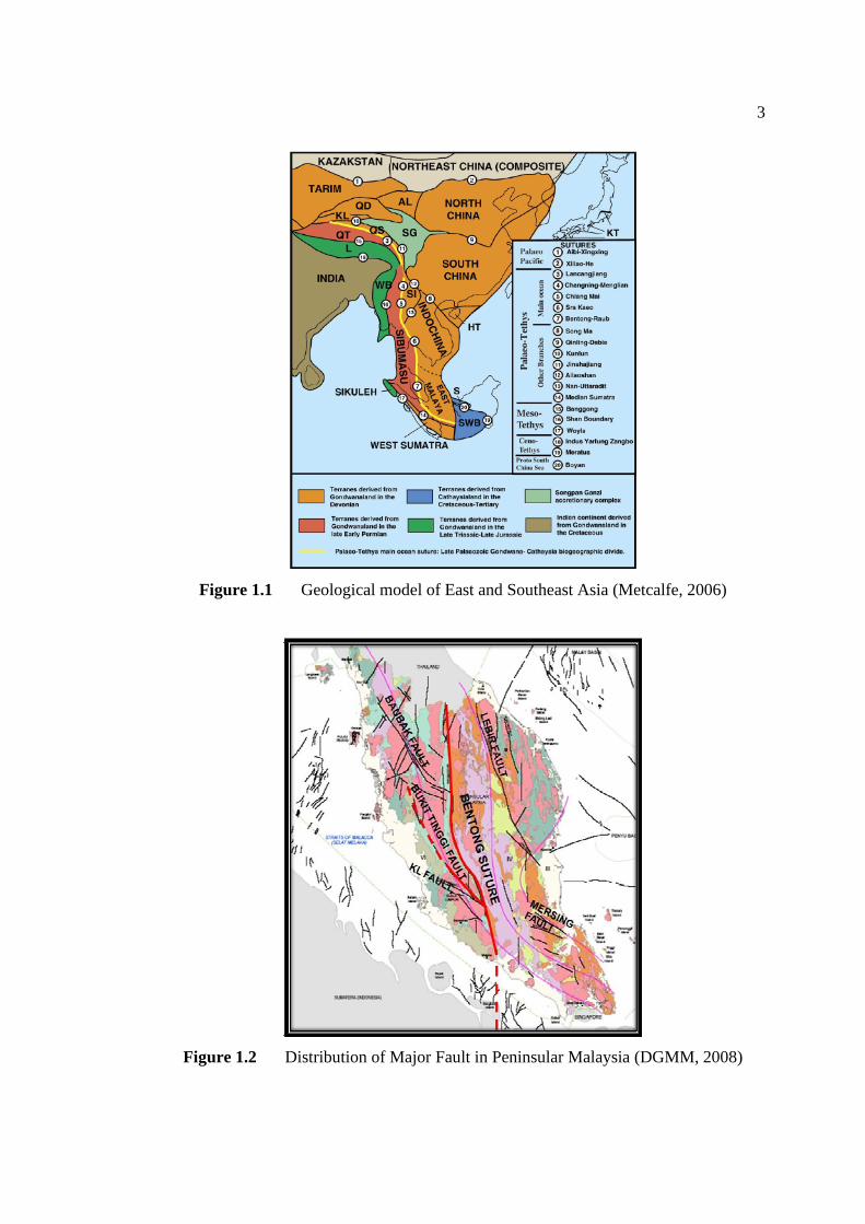
Although Peninsular Malaysia is located in the relative stable continent, but
according to a tectonic model by Metcalfe (2006) it shows that Peninsular Malaysia is
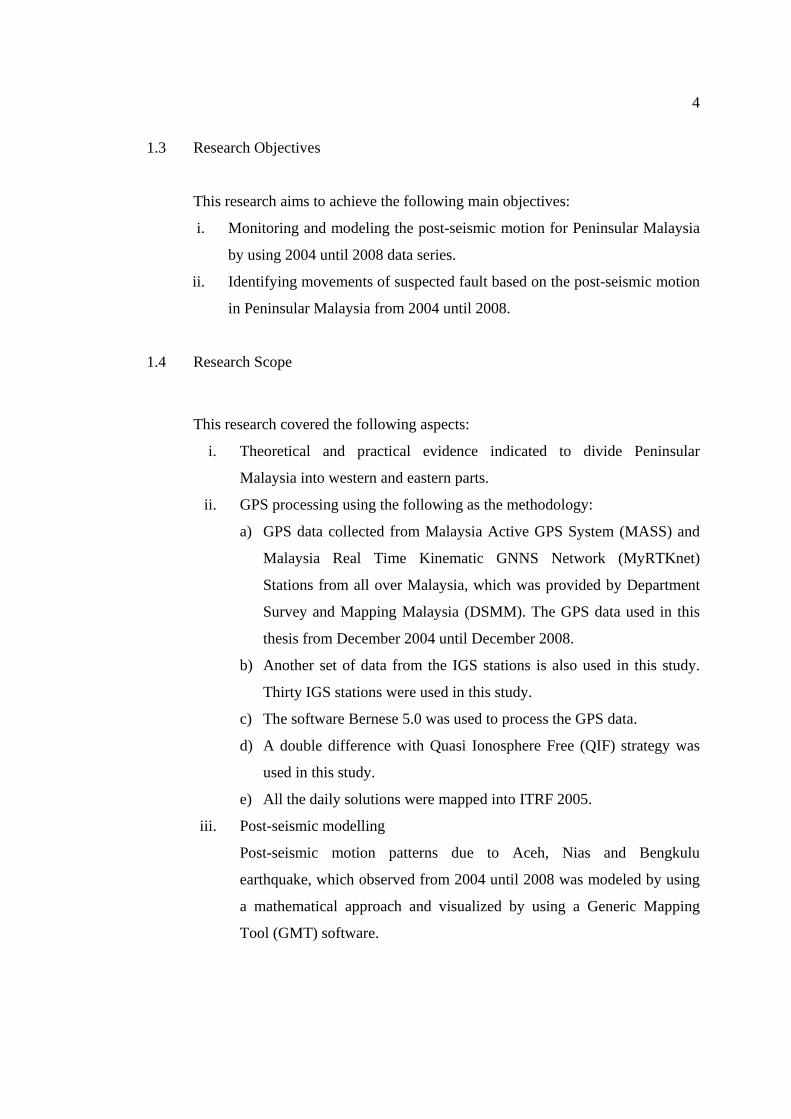
divided into two tectonic blocks (Figure 1.1). Peninsular Malaysia consists of several
inactive major faults such as Bukit Tinggi Fault, Bok Bak Fault, Kuala Lumpur Fault,
Lebir Fault, Lepar Fault, and Mersing Fault (Figure 1.2) (DGMM, 2008). When the big
earthquake in December 2004 occurred, Peninsular Malaysia was deformed into an
irregular form. After the Aceh earthquake, there were several earthquakes also occurred
in the west coast Sumatra in 2005 (Nias) and 2007 (Bengkulu), which caused Peninsular
Malaysia experiencing a complex post-seismic. Because of the complexity of the post-
seismic, a continuous monitoring is needed to investigate the impact of those
earthquakes in Peninsular Malaysia from 2004 until 2008. In the meantime, there were
several tremors recorded in Bukit Tinggi, Kuala Pilah and Jerantut areas from 2007 until
2009. Those tremors are believed as early indication of fault reactivation in Peninsular
Malaysia. The other indication of fault reactivation also can come from the post-seismic
pattern of Peninsular Malaysia. Therefore, it is necessary to investigate whether there is
any seismic activity in the suspected fault due to the Aceh, Nias and Bengkulu
earthquakes.
3
Figure 1.1 Geological model of East and Southeast Asia (Metcalfe, 2006)
Figure 1.2 Distribution of Major Fault in Peninsular Malaysia (DGMM, 2008)
4
1.3 Research Objectives
This research aims to achieve the following main objectives:
i. Monitoring and modeling the post-seismic motion for Peninsular Malaysia
by using 2004 until 2008 data series.
ii. Identifying movements of suspected fault based on the post-seismic motion
in Peninsular Malaysia from 2004 until 2008.
1.4 Research Scope
This research covered the following aspects:
i. Theoretical and practical evidence indicated to divide Peninsular
Malaysia into western and eastern parts.
ii. GPS processing using the following as the methodology:
a) GPS data collected from Malaysia Active GPS System (MASS) and
Malaysia Real Time Kinematic GNNS Network (MyRTKnet)
Stations from all over Malaysia, which was provided by Department
Survey and Mapping Malaysia (DSMM). The GPS data used in this
thesis from December 2004 until December 2008.
b) Another set of data from the IGS stations is also used in this study.
Thirty IGS stations were used in this study.
c) The software Bernese 5.0 was used to process the GPS data.
d) A double difference with Quasi Ionosphere Free (QIF) strategy was
used in this study.
e) All the daily solutions were mapped into ITRF 2005.
iii. Post-seismic modelling
Post-seismic motion patterns due to Aceh, Nias and Bengkulu
earthquake, which observed from 2004 until 2008 was modeled by using
a mathematical approach and visualized by using a Generic Mapping
Tool (GMT) software.
5
iv. Identification of fault movement
The best way to monitor the movement of fault is to establish a series of
field GPS campaign, on the specific areas of major faults in Peninsular
Malaysia. However, there were insufficient funds to do the field
measurement but the fault identification used was based on the existing
GPS infrastructure in Peninsular Malaysia.
1.5 Research Contributions
Malaysia has an established GPS network that provides high precision
positioning in Malaysia, which complies with International standards. The mega thrust
earthquakes caused deformation at the GPS stations in Peninsular Malaysia by creating
an irregular shape, and also may have caused major faults to be reactivated or formed
new minor faults. Therefore, the final results from this study would be an important
input for environmental planning, building construction industry and mapping the high
risk zone of seismic activity.
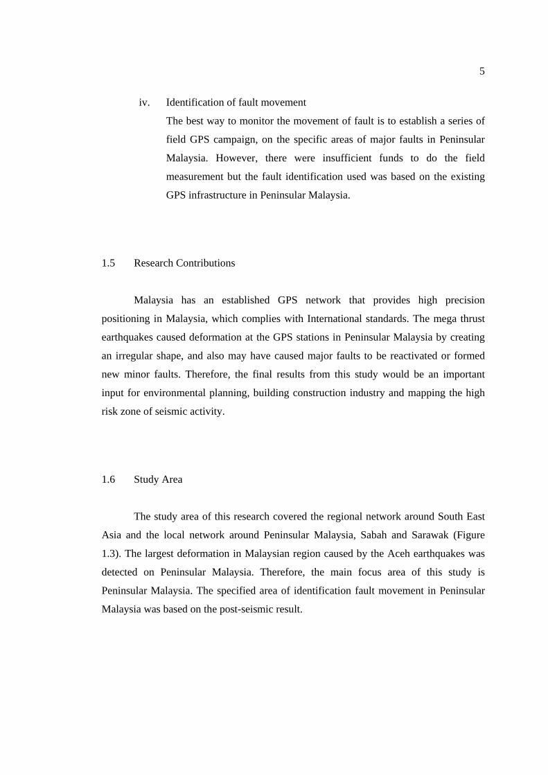
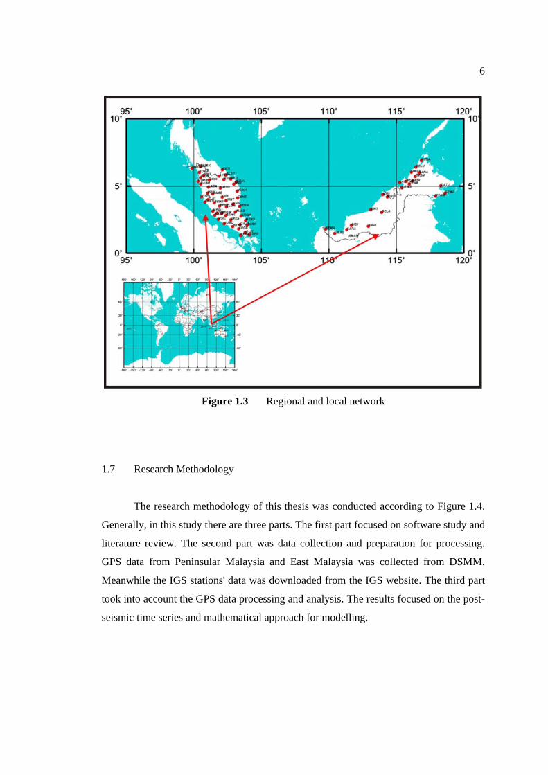
1.6 Study Area
The study area of this research covered the regional network around South East
Asia and the local network around Peninsular Malaysia, Sabah and Sarawak (Figure
1.3). The largest deformation in Malaysian region caused by the Aceh earthquakes was
detected on Peninsular Malaysia. Therefore, the main focus area of this study is
Peninsular Malaysia. The specified area of identification fault movement in Peninsular
Malaysia was based on the post-seismic result.
6
Figure 1.3 Regional and local network
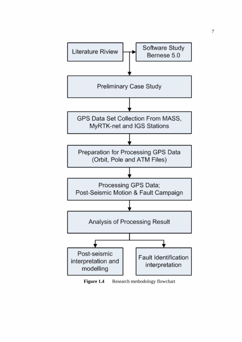
1.7 Research Methodology
The research methodology of this thesis was conducted according to Figure 1.4.
Generally, in this study there are three parts. The first part focused on software study and
literature review. The second part was data collection and preparation for processing.
GPS data from Peninsular Malaysia and East Malaysia was collected from DSMM.
Meanwhile the IGS stations' data was downloaded from the IGS website. The third part
took into account the GPS data processing and analysis. The results focused on the post-
seismic time series and mathematical approach for modelling.
7
Figure 1.4 Research methodology flowchart
8
1.8 Chapter Contents
The thesis contains seven chapters. The first chapter consists of the introduction
to this research. The second chapter discusses the literature study on the plate tectonic,
earthquakes, and tectonic settings of Peninsular Malaysia. The third chapter is about the
Global and local GNSS infrastructures and the application to geodynamic studies. The
fourth chapter is the data collection and processing strategy. The fifth chapter contains
the analysis of the GPS processing results and the interpretation of seismic motions in
Peninsular Malaysia. The sixth chapter contains the analysis of the GPS processing
results of the fault identification. The seventh chapter is the conclusion inclusive of the
recommendation for the improvement of this research in the future. Relevant
information that has not been included in the chapters is appended at the end of the
thesis.