universiti teknikal malaysia melaka - eprints.utem.edu.myeprints.utem.edu.my/16386/1/design of...
TRANSCRIPT
UNIVERSITI TEKNIKAL MALAYSIA MELAKA
BORANG PENGESAHAN STATUS LAPORAN PROJEK SARJANA MUDA
TAJUK: DESIGN OF AUTOMATED GUIDED VEHICLE (AGV) FOR WORKPIECES TRANSPORTATION IN MANUFACTURING PLANT SESI PENGAJIAN: 2014/2015 Saya MOHAMAD ZAWAWI BIN ABDUL RAZAK mengaku membenarkan Laporan PSM ini disimpan di Perpustakaan Universiti Teknikal Malaysia Melaka (UTeM) dengan syarat-syarat kegunaan seperti berikut:
1. Laporan PSM adalah hak milik Universiti Teknikal Malaysia Melaka dan penulis. 2. Perpustakaan Universiti Teknikal Malaysia Melaka dibenarkan membuat salinan
untuk tujuan pengajian sahaja dengan izin penulis. 3. Perpustakaan dibenarkan membuat salinan laporan PSM ini sebagai bahan
pertukaran antara institusi pengajian tinggi.
4. **Sila tandakan ( )
SULIT
TERHAD
TIDAK TERHAD
(Mengandungi maklumat yang berdarjah keselamatan atau kepentingan Malaysia sebagaimana yang termaktub dalam AKTA RAHSIA RASMI 1972)
(Mengandungi maklumat TERHAD yang telah ditentukan oleh organisasi/badan di mana penyelidikan dijalankan)
Alamat Tetap:
NO 82 A, KAMPUNG BELUM BARU
33300 GERIK PERAK DARUL
RIDZUAN
Tarikh: ________________________
Disahkan oleh:
Cop Rasmi: Tarikh: _______________________
** Jika Laporan PSM ini SULIT atau TERHAD, sila lampirkan surat daripada pihak berkuasa/organisasi berkenaan dengan menyatakan sekali sebab dan tempoh laporan PSM ini perlu dikelaskan sebagai SULIT atau TERHAD.
i
DECLARATION
I hereby, declared this report entitled “Design of Automated Guided Vehicle (AGV) for
Workpiece Transportation in Manufacturing Plant” is the result of my own research
except as cited in references.
Signature : ………………………………………………
Author’s Name : ………………………………………………
Date : ………………………………………………
ii
APPROVAL
This report is submitted to the Faculty of Manufacturing Engineering of UTeM as a
partial fulfillment of the requirement for the degree of Bachelor of Manufacturing
Engineering (Robotic and Automation) (Hons.). The member of the supervisory is as
follow:
……………………………………………….
(Project Supervisor)
(Prof. Dr. Bashir Mohamad Bin Bali Mohamad)

iii
ABSTRAK
Laporan projek ini membentangkan kerja-kerja yang dilakukan pada rekabentuk dan
permodelan mudah kenderaan berpandu automatik. AGV yang merupakan salah satu
system yang mengendalikan peralatan yang telah digunakan secara meluas dalam industri
pembuatan kebanyakan hari. Ini adalah kerana ia memberi lebih banyak kemudahan
sistem pengendalian. Konsep asas AGV yang menggabungkan kenderaan berkuasa bateri
dan tidak memerlukan dengan pengaturcaraan keupayaan untuk pemilihan laluan dan
kedudukan. Ia dilengkapi untuk menavigasi dalam rangkaian laluan panduan fleksibel
yang boleh diubahsuai dengan mudah dan berkembang. Perisian untuk mereka bentuk
AGV yang dipilih berdasarkan pengetahuan penulis. Beberapa idea-idea rekabentuk telah
dihasilkan dan dibahagikan kepada dua komponen utama iaitu kenderaan badan dan
rangka struktur. Dari idea-idea ini direka bentuk, perbandingan telah dibuat untuk
memilih idea Reka bentuk yang terbaik dari mereka bentuk AGV itu. Bahagian penting
AGV direka berdasarkan spesifikasi dan keperluan bahagian-bahagian yang perlu
dipasangkan padanya. Senarai semua bahagian perlu direka dan bahagian-bahagian yang
standard dibentangkan dalam laporan ini. Bahagian-bahagian terperinci dan spesifikasi
dibentangkan dalam solid model dengan dimensi yang memenuhi keperluan
pembangunan masa hadapan. Analisis unsur terhingga (FEA) telah digunakan untuk
menganalisis rekabentuk struktur AGV. Tekanan, anjakan, perubahan bentuk dan faktor
keselamatan adalah diperolehi dari analisis dan dibentangkan. Untuk pembangunan masa
depan, ia dicadangkan untuk fabrikasi dan menguji rekabentuk AGV. Daripada keputusan
ujian, tindakan perlu diambil (jika perlu) untuk penambahbaikan Reka bentuk AGV.
iv
ABSTRACT
This project report presents the work done on the design and soft modeling of automated
guided vehicle. An AGV is one of a material handling equipment that has been used
widely in most manufacturing industry today. This is because it provides more flexibility
to the material handling system. The basic concept of the AGV incorporates battery-
powered and driverless vehicles with programming capabilities for path selection and
positioning. They are equipped to navigate a flexible guide path network that can be
easily modified and expanded. The software for designing the AGV is chosen based on
the author knowledge. Several design ideas have been generated and divided into two
major components which are the body vehicle and the structure frame. From these
designed ideas, a comparison has been made to choose the best design idea from
designing the AGV. The AGV important parts are designed based on the specification
and requirement of the parts to be attached to it. The list of all parts needs to be fabricated
and the standard parts are presented in this report. The detail of the parts and their
specifications are presented in solid model with the dimensions which fulfills the
requirement for future development. Finite element analysis (FEA) has been used to
analyse the design of the AGV structure. The stress, displacement, deformation and
factor of safety are obtained from the analysis and presented. For future development, it
was suggested to fabricate and test the designed AGV. From the test result, action should
be taken (if necessary) for further improvement of the designed AGV design.

v
DEDICATION
My special dedication to my beloved mother, Che Embun Binti Yaacob, for their loves
and supports which never end and with the loves and supports given to me, I managed to
go through 4 years of my study which full with challenges and hunches. To beloved
friends of 4BMFA who have been with me through my journey in education. Also thank
you for all the motivation and their beliefs towards me.
vi
ACKNOWLEDGEMENT
I would like to express my appreciation to all those who provided me the possibility to
complete this report. A special gratitude give to my final year project supervisor, Prof.
Dr. Bashir Mohamad Bin Bali Mohamad, whose contribution in suggestion and
encouragement, helped to coordinate my project especially in writing this report.
vii
TABLE OF CONTENT
Declaration i
Approval ii
Abstrak iii
Abstract iv
Dedication v
Acknowledgement vi
Table of Content vii
List of Tables x
List of Figures xi
List of Abbreviations, Symbols and Nomenclature xiv
CHAPTER 1: INTRODUCTION 1
1.1 Background of study 1
1.2 Problem statement 2
1.3 Project objective 3
1.4 Scope of the project 3
CHAPTER 2: LITERATURE REVIEW 4
2.1 AGVs Classification 4
2.1.1 Guide path Determination 5
2.1.2 Vehicle Load Capacity 6
2.1.3 Vehicle Addressing Mechanism 8
2.2 Automated Guided Vehicle (AGV) 9
2.2.1 Driverless Train 9
2.2.2 Pallet Trucks 10
2.2.3 Unit Load Carrier 10
viii
2.3 AGV Navigation 11
2.3.1 Fixed Path 11
2.3.1 Free Ranging or Non-wire Navigation 13
2.4 Positioning Techniques 14
2.4.1 Odometry 15
2.4.2 Inertial Navigation 16
2.4.3 Magnetic Compasses 16
2.4.4 Active Beacon 17
2.4.5 Global Positioning System (GPS) 18
2.4.6 Landmark Navigation 19
2.4.7 Map Based Positioning 20
2.5 Steering Consideration 21
2.5.1 Steered-Wheel System 22
2.5.2 Skid-Steered System 24
2.5.3 Ackerman Steering 25
2.5.4 Differential Drive System 26
2.6 Microcontroller 33
2.7 Computer-Aided Design (CAD) software 35
2.7.1 AutoCAD 35
2.7.2 SolidWorks 35
2.7.3 Catia 36
2.8 Conclusion 36
CHAPTER 3: METHODOLOGY 37
3.1 Flow Chart of Project 37
3.2 Generate preliminary design ideas and specification 39
3.3 Analysis of the preliminary design ideas and specification 42
3.4 Conclusion 44
ix
CHAPTER 4: DESIGN AND ANALYSIS OF THE AUTOMATED
GUIDED VEHICLE 45
4.1 AGV parts 45
4.1.1 Assembly design and AGV structure 48
4.1.2 Parts specification 51
4.2 Model analysis 60
4.3 Von Mises Stress analysis 61
4.3.1 Element quality 61
4.3.2 Direct method computation 64
4.4 Factor of Safety 67
4.5 Encoder DC motor 68
CHAPTER 5: CONCLUSION AND SUGGESTION FOR FUTURE WORK 71
5.1 Conclusion 71
5.2 Suggestion for future work 72
REFERENCES 73
APPENDICES 75
A Project Gantt Chart 76
B Detail drawings and dimensions of the parts to be fabricated 77

x
LIST OF TABLES
3.1 The comparison for design ideas of body vehicle 41
3.2 The comparison for design ideas of structure frame 41
4.1 List of parts need to be fabricated 46
4.2 List of standard parts 47
4.3 Shows the fabricated parts and their specifications 51
4.4 Shows the standard parts and their specifications 55
4.5 The element quality of the chassis of AGV 61
4.6 Parameter of Aluminium Alloy 6061 61
4.7 Applied load resultant on chassis of AGV 62
4.8 Minimum and maximum pivot 63
4.9 Minimum pivot 63
4.10 Translational pivot distribution 63
4.11 The values of force (x,y,z) and moment (x,y,z) of model 64
4.12 Show the detailed about the pin connection encoder motor 69
xi
LIST OF FIGURES
1.1 AGV application for warehousing industry 1
1.2 The present condition between bandsaw machine and CNC machine at FKP 2
2.1 Deadlock situation in manufacturing systems 6
2.2 Single load vehicle 7
2.3 AGVS Classification Scheme 8
2.4 Driverless train 10
2.5 Pallet truck control by human operator 11
2.6 Unit load carrier for heavy product 12
2.7 Existing navigation technologies of AGV 14
2.8 Magnetic compasses used to detected the route of AGV 17
2.9 Active beacon system 18
2.10 GPS working principle 19
2.11 A map claim with landmarks labeled 20
2.12 A typical scan of a room 21
2.13 (a) Ackerman-steered system; (b) Differential-steered system 22
2.14 Steered-wheel system in tricycle configuration 23
2.15 Steered-wheel configuration as used in automobiles 23
2.16 Skid-steered system in four wheel vehicle 25
2.17 Schematic of a robot with Ackerman steering 26
2.18 Differential drive system in most robots 27
xii
2.19 Differential steering is a result of different wheel speeds causing the
robot to change direction 28
2.20 Basic operation of a shaft encoder 29
2.21 Pulses showing distance travelled by an AGV obtained by the use of encoder 30
2.22 Path of wheels through a turn 32
2.23 Microchip 16F877A is one of microcontroller 33
2.24 A typical microprocessor system 34
3.1 Flow chart of project methodology 38
3.2 Sketch of the body vehicle design ideas 40
3.3 Sketch of the structure frame design ideas 41
3.4 Conceptual design of automated guided vehicle (AGV) 43
4.1 The assembly design of automated guided vehicle 48
4.2 Structure of automated guided vehicle 49
4.3 Exploded view of AGV with the name of each part 50
4.4 Aluminium Alloy 6061-T6 chassis of AGV 60
4.5 Boundary condition of AGV chassis 62
4.6 Static Case Solution-deformed mesh 1 64
4.7 Static Case Solution 1-Von Mises Stress (nodal value) 2 65
4.8 Static Case Solution 1-Von Mises Stress (nodal value) 2 65
4.9 Static Case Solution 1-Translational displacement vector 66
4.10 Show the maximum of stress on chassis of AGV 67

xiii
4.11 Show the pin connection of encoder DC motor 68
4.12 Show the connection motor to PIC microcontroller 69
xiv
LIST OF ABBREVIATIONS, SYMBOLS AND
NOMENCLATURE
AGV - Automated Guided Vehicle
CNC - Computer Numerical Control
CAD - Computer-Aided Design
CAM - Computer-Aided Manufacturing
CPU - Central Unit Processing
DC - Direct Current
FEA - Finite Element Analysis
GPS - Global Positioning System
RPM - Revolution per Minutes
PC - Personal Computer
3D - Three Dimensional
2D - Two Dimensional
1
CHAPTER 1
INTRODUCTION
1.1 Background of study
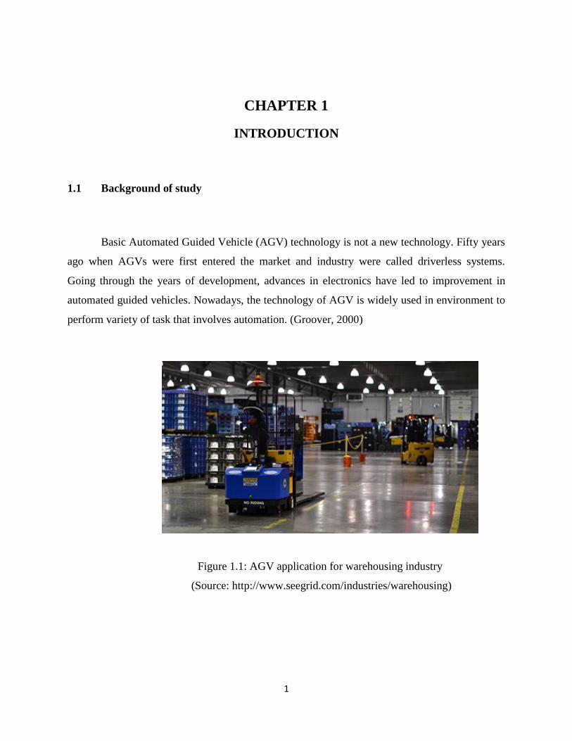
Basic Automated Guided Vehicle (AGV) technology is not a new technology. Fifty years
ago when AGVs were first entered the market and industry were called driverless systems.
Going through the years of development, advances in electronics have led to improvement in
automated guided vehicles. Nowadays, the technology of AGV is widely used in environment to
perform variety of task that involves automation. (Groover, 2000)
Figure 1.1: AGV application for warehousing industry
(Source: http://www.seegrid.com/industries/warehousing)
2
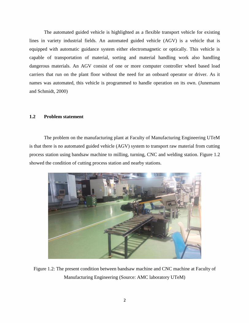
The automated guided vehicle is highlighted as a flexible transport vehicle for existing
lines in variety industrial fields. An automated guided vehicle (AGV) is a vehicle that is
equipped with automatic guidance system either electromagnetic or optically. This vehicle is
capable of transportation of material, sorting and material handling work also handling
dangerous materials. An AGV consist of one or more computer controller wheel based load
carriers that run on the plant floor without the need for an onboard operator or driver. As it
names was automated, this vehicle is programmed to handle operation on its own. (Junemann
and Schmidt, 2000)
1.2 Problem statement
The problem on the manufacturing plant at Faculty of Manufacturing Engineering UTeM
is that there is no automated guided vehicle (AGV) system to transport raw material from cutting
process station using bandsaw machine to milling, turning, CNC and welding station. Figure 1.2
showed the condition of cutting process station and nearby stations.
Figure 1.2: The present condition between bandsaw machine and CNC machine at Faculty of
Manufacturing Engineering (Source: AMC laboratory UTeM)
3
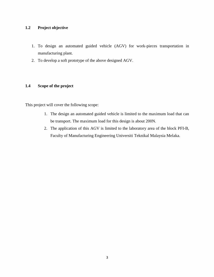
1.2 Project objective
1. To design an automated guided vehicle (AGV) for work-pieces transportation in
manufacturing plant.
2. To develop a soft prototype of the above designed AGV.
1.4 Scope of the project
This project will cover the following scope:
1. The design an automated guided vehicle is limited to the maximum load that can
be transport. The maximum load for this design is about 200N.
2. The application of this AGV is limited to the laboratory area of the block PFI-B,
Faculty of Manufacturing Engineering Universiti Teknikal Malaysia Melaka.
4
CHAPTER 2
LITERATURE REVIEW
In this chapter, we will discuss more about Automated Guided Vehicle System, its classification,
the vehicle load capacity, the vehicle itself and the application of the vehicle in material handling
and industry. The reference sources and information are obtained from website, books, journals,
articles, conference and magazine. This chapter is to enhance the knowledge of student about the
project.
2.1 AGVs Classification
Modern AGV system differs from the classic one as described for instance in the book of
Junemann and Schmidt (2000) and Tompkins et al. (2003) in several respect. Rather than using
fixed paths, many modern AGV are free ranging, which means the path of the vehicle are
software programmed and can be change relatively easy when new stations or even flows are
added. Modern technology also allows the vehicle to make decisions on its own compare to the
past when control was perform by central controllers. This leads to adaptive, self-learning system
of the AGV (Tuan Le-Anh and De Koster). In this section, AGVs classification according to the
journal by Peter et al will describe.
According to the journal, the automated guided vehicle system can be divided into three
basic levels such as below:
i. Guided path determination
a) Static path
i. Unidirectional
ii. Bidirectional
b) Dynamic path
5
ii. Vehicle capacity
a) Single unit load
b) Multiple loads
iii. Vehicle addressing mechanism
a) Direct address
b) Indirect address
2.1.1 Guide path Determination
Automated Guided Vehicle (AGVs) guide paths can be determined in two ways, which
are static or dynamic determination. Static guide paths system, it can be further divided into
unidirectional and bidirectional systems. In static guide path, the vehicles use a set of
predetermined paths between possible origin and destinations. Variety of guidance mechanisms
can be used such as wires embedded in the floor, chemical or optical sensors, dead reckoning and
mapping of the paths by using software.
In unidirectional system, the vehicle will only travel in single direction following
predetermined lane. If many vehicle are used, each of them will have its own lane or path and
each of the lane is controlled independently even through the directions are different. This type
of system is easier to control as deadlocking and collision problems can be avoided. In
bidirectional system, vehicles can travel in forward and backward movement using the same
guide path. In order to do so, a turning or turnaround point is specified for the vehicle. Although
this type of system can bring improvement in productivity and less vehicle usage, however, the
control system is complex since multiple vehicle share the same guide path and must be able to
avoid deadlock situation.
6
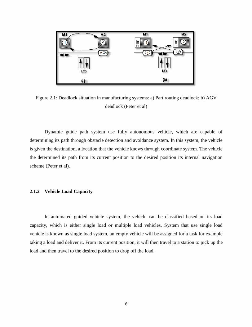
Figure 2.1: Deadlock situation in manufacturing systems: a) Part routing deadlock; b) AGV
deadlock (Peter et al)
Dynamic guide path system use fully autonomous vehicle, which are capable of
determining its path through obstacle detection and avoidance system. In this system, the vehicle
is given the destination, a location that the vehicle knows through coordinate system. The vehicle
the determined its path from its current position to the desired position its internal navigation
scheme (Peter et al).
2.1.2 Vehicle Load Capacity
In automated guided vehicle system, the vehicle can be classified based on its load
capacity, which is either single load or multiple load vehicles. System that use single load
vehicle is known as single load system, an empty vehicle will be assigned for a task for example
taking a load and deliver it. From its current position, it will then travel to a station to pick up the
load and then travel to the desired position to drop off the load.
7
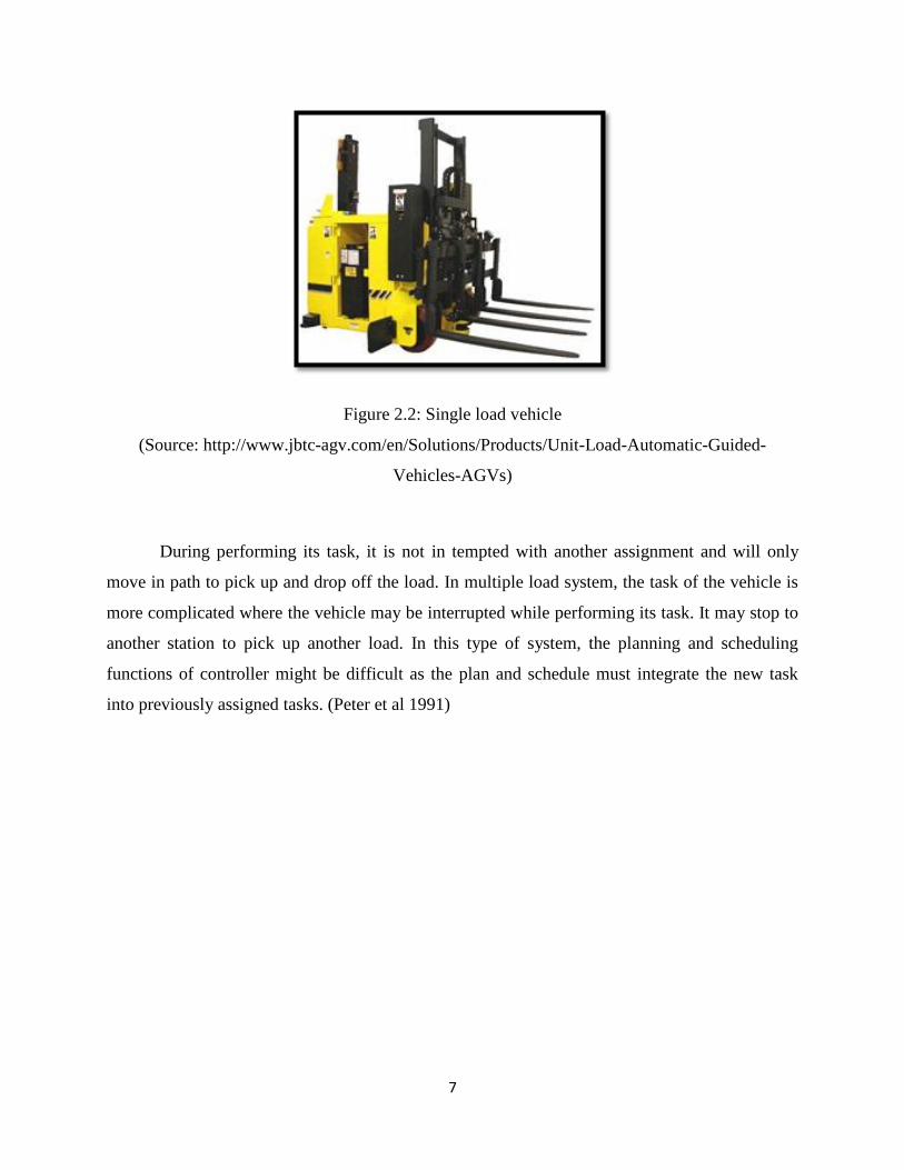
Figure 2.2: Single load vehicle
(Source: http://www.jbtc-agv.com/en/Solutions/Products/Unit-Load-Automatic-Guided-
Vehicles-AGVs)
During performing its task, it is not in tempted with another assignment and will only
move in path to pick up and drop off the load. In multiple load system, the task of the vehicle is
more complicated where the vehicle may be interrupted while performing its task. It may stop to
another station to pick up another load. In this type of system, the planning and scheduling
functions of controller might be difficult as the plan and schedule must integrate the new task
into previously assigned tasks. (Peter et al 1991)

8
2.1.3 Vehicle Addressing Mechanism
Vehicle addressing system in AGVs can be grouped into two, which are direct or indirect
address system. In direct address system, any vehicle is allowed to visit any stations available in
the same system. This system is much alike the taxi service. The planning function for this
system routes vehicle from its current location to its destination considering the current status of
the system. In other words the routes are not determined in advanced. Vehicles must be assigned
to tasks since vehicle are not restricted to serve any particular station. The planning function
might be complicated since the location of the vehicle is not known initially but only changes
upon system changes.
Figure 2.3: AGVS Classification Scheme (Peter et al)
In indirect address system, vehicles will stop at stations in a fixed sequence, which is
more likely a bus service. The routes are predetermined as part of the system design, not one of
9
the controller planning function. Compare to direct address system, the dispatching in this
system is straight forward. As the route of the vehicle is predetermined, it will pick up and drop
off loads when it reach each stations in its route (Peter et al).
2.2 Automated Guided Vehicle (AGV)
According to (Groover, 1987), Automated Guided Vehicles (AGV) can be grouped into
three categories as below:
1. Driverless train
2. Pallet trucks
3. Unit load carriers
2.2.1 Driverless Train
Driverless train basically consists of towing vehicle, which is the AGV that pull or more
trailers forming a train. This type of AGV is used when heavy payloads involve and loads need
to be travel in large distances like in a warehouse. The task usually involves intermediate pick up
and drop off points along its path. (Groover, 2001)