intelligent active force control of a vehicle...
TRANSCRIPT

INTELLIGENT ACTIVE FORCE CONTROL
OF A VEHICLE SUSPENSION SYSTEM
GIGIH PRIYANDOKO
UNIVERSITI TEKNOLOGI MALAYSIA
BAHAGIAN A – Pengesahan Kerjasama*
Adalah disahkan bahawa projek penyelidikan tesis ini telah dilaksanakan melalui
kerjasama antara ________________________ dengan _______________________
Disahkan oleh : ............................................................... Tarikh: .................................
Tanda tangan : ...............................................................
Jawatan : ...............................................................
(Cop rasmi)
*Jika penyediaan tesis/projek melibatkan kerjasama
===========================================================
BAHAGIAN B – Untuk Kegunaan Pejabat Sekolah Pengajian Siswazah
Tesis ini telah diperiksa dan diakui oleh:
Nama dan Alamat Pemeriksa Luar : Prof. Ir. Hj. Abdul Rahman bin Omar
Dekan
Fakulti Kejuruteraan Mekanikal
Universiti Teknologi MARA (UiTM)
40450 Shah Alam, Selangor.
Nama dan Alamat Pemeriksa Dalam : Prof. Madya Dr. Mohd Azman bin Zainul Abidin
Fakulti Kejuruteraan Mekanikal
UTM, Skudai
Nama Penyelia Lain (jika ada) : .........................................................................
..........................................................................
..........................................................................
Disahkan oleh Timbalan Pendaftar di SPS
Tanda tangan : ................................................................ Tarikh: ................................
Nama : KHASIM BIN ISMAIL
INTELLIGENT ACTIVE FORCE CONTROL
OF A VEHICLE SUSPENSION SYSTEM
GIGIH PRIYANDOKO
A thesis submitted in fulfilment of the
requirements for the award of the degree of
Doctor of Philosophy (Mechanical Engineering)
Faculty of Mechanical Engineering
Universiti Teknologi Malaysia
APRIL 2009

iii
I dedicated this thesis to my beloved wife Amik Purbowati and
my children Fadhil, Shofy, Faiz, Inas, Farobi, Farhan and Hanin

iv
ACKNOWLEDGEMENT
All praise and glory is to almighty ALLAH subhanahu wa ta'ala who gave me
the courage and patience to carry out this work, and peace and blessings of Allah be
upon his last prophet Mohammad sholallohu alaihi wassalam.
I would like to express my deep gratitude to my thesis supervisor Prof. Dr.
Musa Mailah and co-supervisor Prof. Dr. Hishamuddin Jamaluddin for their
unconditional help, encouragement and valuable suggestions during the preparation
of my thesis. They were patient with me and did not hesitate in helping me by all
means. There critical views helped me in forming a strong research perspective. I am
also indebted to Mr. Mohamad Akmal Baharain who helped me substantially in the
practical development of the test rig, and to all my colleagues who gave me support
in technical issues, discussion and so on.
I would like to thank the Malaysian Ministry of Science, Technology and
Innovation (MOSTI), Universiti Teknologi Malaysia (UTM) and Universitas
Widyagama for their continuous support in the research work. This research was
supported by an e-Science fund grant (No. 03-02-06-0123EA001).
I want to especially thank my parent, my family and my mother in law for
their continuous support and encouragement. I also want to thank my children; they
are Fadhil, Shofy, Faiz, Inas, Farobi, Farhan and Hanin for being in my life. Finally,
I want to specially thank my dear love, Amik Purbowati, for believing in me, her
enduring love and friendship. It has been my greatest enjoyment to have her as my
wife.

v
ABSTRACT
Active suspension control aims to suppress the undesirable vibration and
other loading effects and should provide improvements in term of passenger comfort.
This study deals with the design and implementation of robust active force control
(AFC)-based schemes that incorporates artificial intelligence techniques plus a
number of feedback control strategies applied to a vehicle suspension system. The
overall proposed control system essentially comprises four feedback control loops,
namely, an innermost loop for force tracking of the pneumatic actuator using a
proportional-integral controller, two intermediate loops applying the skyhook and
AFC strategy for the compensation of the disturbances and an outermost loop for the
computation of the desired force for the actuator using a proportional-integral-
derivative controller. Adaptive neural network and adaptive fuzzy were proposed and
employed to compute the inverse dynamics of the nonlinear pneumatic actuator and
estimated mass of the system within the AFC loop. The integration of all the
interrelated elements leads to the formation of two main proposed schemes known as
the Skyhook Adaptive Fuzzy Active Force Control and Skyhook Adaptive Neuro
Active Force Control. The suspension system was modelled based on a two degree-
of-freedom quarter car configuration. A number of road profiles were also modelled
as the main disturbance elements to evaluate the system robustness and vehicle
dynamic performance related to ride comfort. Simulation results both in time and
frequency domains demonstrate the effectiveness of the proposed AFC-based
schemes in countering the disturbances and other loading conditions. The schemes
show evidence of at least 33.9% improvement in performance over the passive
suspension. This is complemented by an experimental study on a developed full scale
quarter car suspension test rig which shows a very good agreement with the
simulation counterpart.
vi
ABSTRAK
Kawalan ampaian aktif bertujuan untuk mengurangkan kesan getaran dan
bebanan yang tidak dikehendaki dan seharusnya dapat memperbaiki kriteria
keselesaan penumpang. Penyelidikan ini mengkaji reka bentuk dan pelaksanaan skim
lasak terhadap satu sistem ampaian kenderaan berasaskan Kawalan Daya Aktif
(AFC) yang memuatkan teknik Kepintaran Buatan dan beberapa strategi kawalan
bersuap balik. Sistem kawalan keseluruhan yang dicadangkan merangkumi empat
gelung kawalan bersuap balik, iaitu satu gelung terkedalam untuk tujuan penjejakan
daya penggerak pneumatik menggunakan pengawal berkadaran-kamiran, dua gelung
antara menggunakan strategi Skyhook dan AFC untuk memampas daya gangguan
dan satu gelung pada kedudukan paling luar untuk mengira daya yang diperlukan
oleh penggerak menggunakan pengawal berkadaran-kamiran-terbitan. Rangkaian
Neural Adaptif dan Logik Kabur Adaptif telah dicadangkan dan diguna untuk
mendapatkan dinamik songsang bagi penggerak pneumatik tak linar dan juga jisim
anggaran sistem dalam gelung AFC. Kesepaduan kesemua unsur yang berkaitan
menghasilkan dua skim utama yang dikenali sebagai Kawalan Daya Aktif Logik
Kabur Adaptif Skyhook dan Kawalan Daya Aktif Neuro Adaptive Skyhook. Sistem
ampaian dimodel berasaskan tatarajah kenderaan sukuan yang mempunyai dua
darjah kebebasan. Beberapa profil jalan juga dimodel sebagai unsur gangguan utama
bagi menilai kelasakan sistem dan juga prestasi dinamik kenderaan berkaitan dengan
keselesaan tunggangan dan pengelolaan jalan. Hasil penyelakuan menunjukkan
keberkesanan skim cadangan berasaskan-AFC dalam menghadapi gangguan dan
keadaan bebanan lain. Skim juga mempamerkan sekurang-kurangnya 33.9%
pembaikan prestasi tercapai jika dibandingkan dengan ampaian pasif. Ini
diperkuatkan oleh penghasilan kajian ujikaji terhadap suatu rig ujikaji ampaian
kenderaan sukuan berskala penuh yang menunjukkan keserasian yang baik dengan
keputusan yang diperoleh melalui penyelakuan.
vii
TABLES OF CONTENTS CHAPTER TITLE PAGE
DECLARATION ii DEDICATION iii ACKNOWLEDGEMENT iv ABSTRACT v ABSTRAK vi TABLE OF CONTENTS vii LIST OF TABLES xi LIST OF FIGURES xiii LIST OF ABREVIATIONS xviii LIST OF SYMBOLS xix LIST OF APPENDICES xxi
1 INTRODUCTION 1
1.1 Introduction 1
1.2 Research Background 2
1.3 Problem Statements 5
1.4 Objectives and Scope of the Research 6
1.5 Research Contributions 7
1.6 Organization of the Thesis 8
2 LITERATURE REVIEW 11
2.1 Introduction 11
2.2 Classification of Vehicle Suspension Systems 12
2.2.1 Passive Suspension 12
2.2.2 Semi-Active Suspension 13
2.2.3 Active Suspension 15
2.3 Performance Index 16
2.4 Pneumatic Active Suspension Control Strategies 18
2.5 Active Force Control 19
2.6 Summary 23
viii
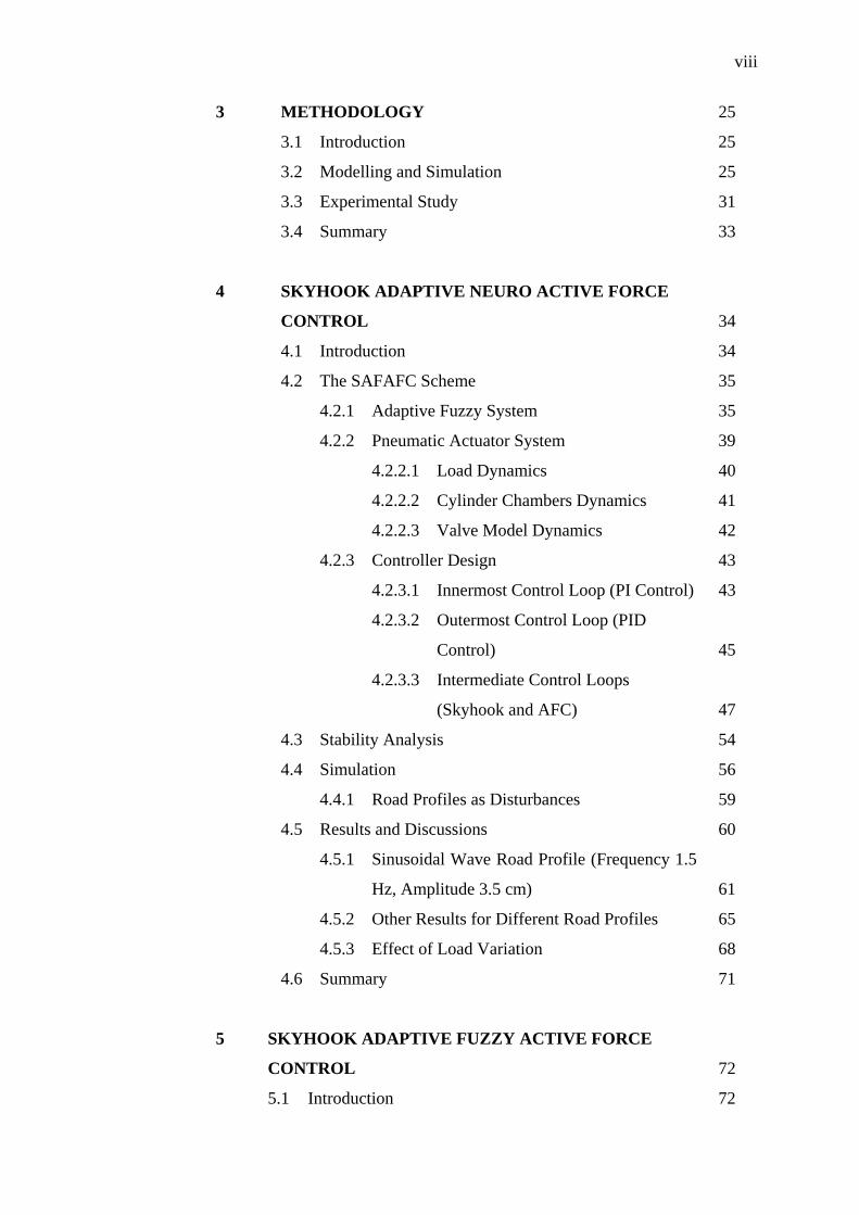
3 METHODOLOGY 25
3.1 Introduction 25
3.2 Modelling and Simulation 25
3.3 Experimental Study 31
3.4 Summary 33
4 SKYHOOK ADAPTIVE NEURO ACTIVE FORCE
CONTROL 34
4.1 Introduction 34
4.2 The SAFAFC Scheme 35
4.2.1 Adaptive Fuzzy System 35
4.2.2 Pneumatic Actuator System 39
4.2.2.1 Load Dynamics 40
4.2.2.2 Cylinder Chambers Dynamics 41
4.2.2.3 Valve Model Dynamics 42
4.2.3 Controller Design 43
4.2.3.1 Innermost Control Loop (PI Control) 43
4.2.3.2 Outermost Control Loop (PID
Control) 45
4.2.3.3 Intermediate Control Loops
(Skyhook and AFC) 47
4.3 Stability Analysis 54
4.4 Simulation 56
4.4.1 Road Profiles as Disturbances 59
4.5 Results and Discussions 60
4.5.1 Sinusoidal Wave Road Profile (Frequency 1.5
Hz, Amplitude 3.5 cm) 61
4.5.2 Other Results for Different Road Profiles 65
4.5.3 Effect of Load Variation 68
4.6 Summary 71
5 SKYHOOK ADAPTIVE FUZZY ACTIVE FORCE
CONTROL 72
5.1 Introduction 72
ix
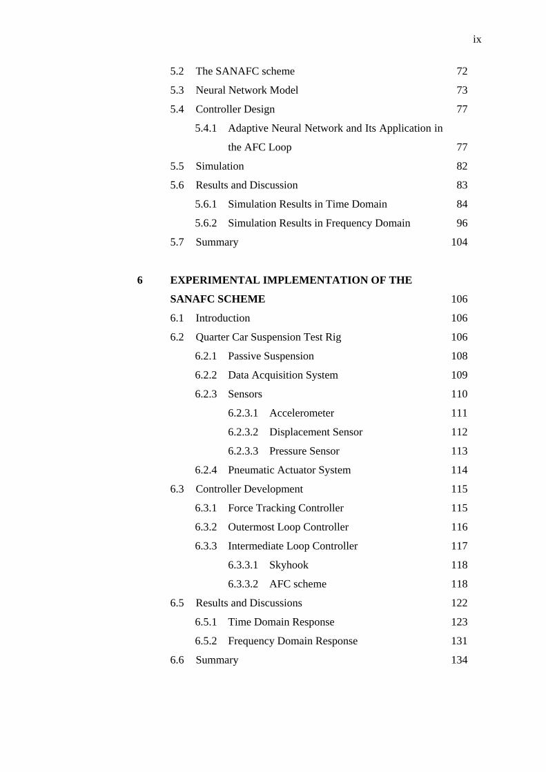
5.2 The SANAFC scheme 72
5.3 Neural Network Model 73
5.4 Controller Design 77
5.4.1 Adaptive Neural Network and Its Application in
the AFC Loop 77
5.5 Simulation 82
5.6 Results and Discussion 83
5.6.1 Simulation Results in Time Domain 84
5.6.2 Simulation Results in Frequency Domain 96
5.7 Summary 104
6 EXPERIMENTAL IMPLEMENTATION OF THE
SANAFC SCHEME 106
6.1 Introduction 106
6.2 Quarter Car Suspension Test Rig 106
6.2.1 Passive Suspension 108
6.2.2 Data Acquisition System 109
6.2.3 Sensors 110
6.2.3.1 Accelerometer 111
6.2.3.2 Displacement Sensor 112
6.2.3.3 Pressure Sensor 113
6.2.4 Pneumatic Actuator System 114
6.3 Controller Development 115
6.3.1 Force Tracking Controller 115
6.3.2 Outermost Loop Controller 116
6.3.3 Intermediate Loop Controller 117
6.3.3.1 Skyhook 118
6.3.3.2 AFC scheme 118
6.5 Results and Discussions 122
6.5.1 Time Domain Response 123
6.5.2 Frequency Domain Response 131
6.6 Summary 134
x
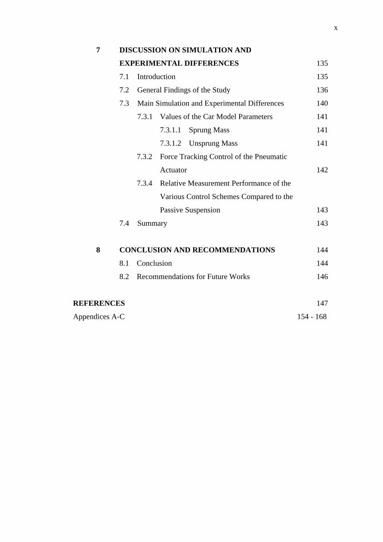
7 DISCUSSION ON SIMULATION AND
EXPERIMENTAL DIFFERENCES 135
7.1 Introduction 135
7.2 General Findings of the Study 136
7.3 Main Simulation and Experimental Differences 140
7.3.1 Values of the Car Model Parameters 141
7.3.1.1 Sprung Mass 141
7.3.1.2 Unsprung Mass 141
7.3.2 Force Tracking Control of the Pneumatic
Actuator 142
7.3.4 Relative Measurement Performance of the
Various Control Schemes Compared to the
Passive Suspension 143
7.4 Summary 143
8 CONCLUSION AND RECOMMENDATIONS 144
8.1 Conclusion 144
8.2 Recommendations for Future Works 146
REFERENCES 147
Appendices A-C 154 - 168
xi
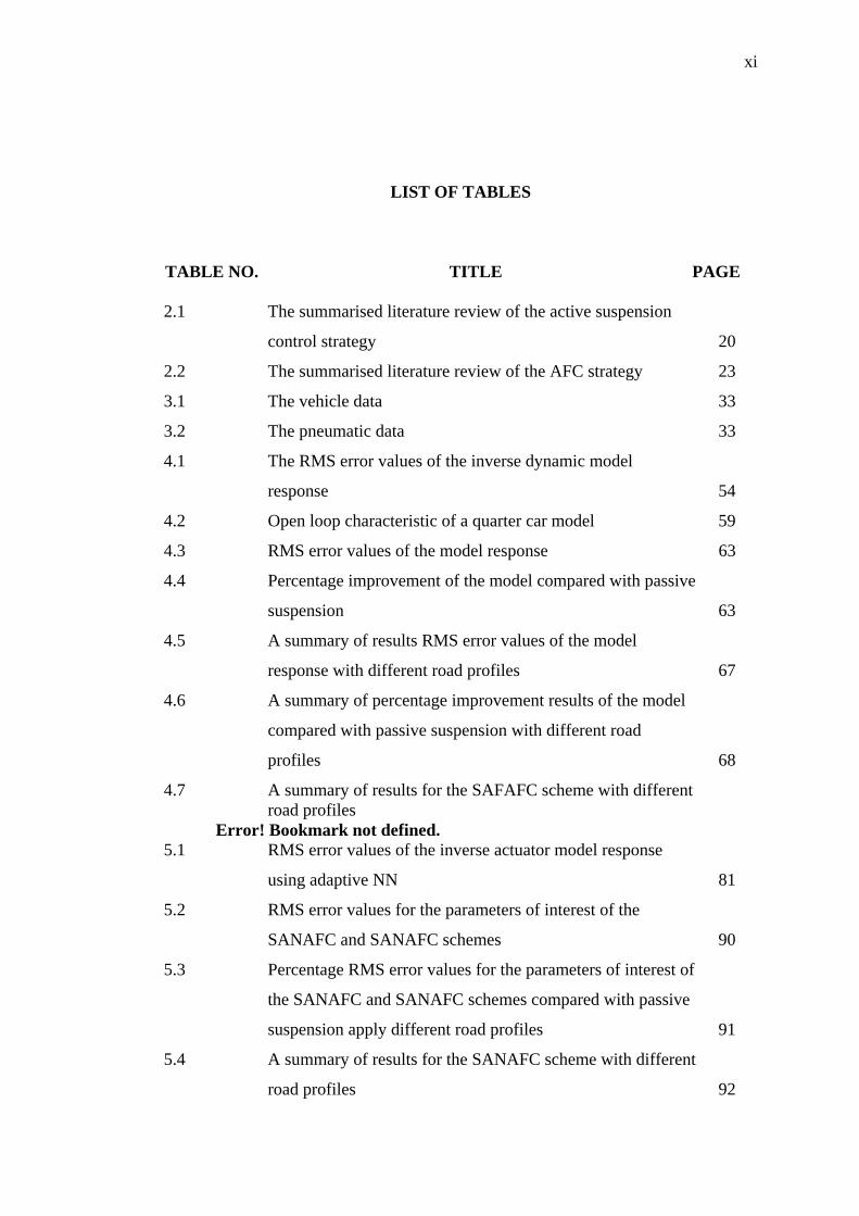
LIST OF TABLES
TABLE NO.
TITLE PAGE
2.1 The summarised literature review of the active suspension
control strategy 20
2.2 The summarised literature review of the AFC strategy 23
3.1 The vehicle data 33
3.2 The pneumatic data 33
4.1 The RMS error values of the inverse dynamic model
response 54
4.2 Open loop characteristic of a quarter car model 59
4.3 RMS error values of the model response 63
4.4 Percentage improvement of the model compared with passive
suspension 63
4.5 A summary of results RMS error values of the model
response with different road profiles 67
4.6 A summary of percentage improvement results of the model
compared with passive suspension with different road
profiles 68
4.7 A summary of results for the SAFAFC scheme with different road profiles
Error! Bookmark not defined. 5.1 RMS error values of the inverse actuator model response
using adaptive NN 81
5.2 RMS error values for the parameters of interest of the
SANAFC and SANAFC schemes 90
5.3 Percentage RMS error values for the parameters of interest of
the SANAFC and SANAFC schemes compared with passive
suspension apply different road profiles 91
5.4 A summary of results for the SANAFC scheme with different
road profiles 92

xii
6.1 Responses of the SANAFC, PID and passive suspension
schemes 129
6.2 Percentage responses of the SANAFC and PID compare with
passive suspension schemes 130
6.3 A summary of results for the SANAFC scheme with different
road profiles 131
7.1 A summary of average percentage improvement results for
the SAFAFC and SANAFC schemes compared with passive
suspension using different road profiles 138
7.2 A summary of results for the SANAFC scheme with different
road profiles 139
xiii
LIST OF FIGURES FIGURE NO. TITLE
PAGE
1.1 AFC concept applied to an active suspension system 5
2.1 Passive suspension system 13
2.2 Semi-active suspension system 14
2.3 Active suspension system 16
2.4 Power spectral density of various terrains 17
2.5 Human tolerance limits for vertical vibration 18
3.1 The flowchart of the research methodology 26
4.1 The proposed SAFAFC scheme 36
4.2 The structure of a fuzzy logic controller 38
4.3 A representation of the Gaussian membership function 39
4.4 The adaptive fuzzy structure 39
4.5 The pneumatic system 41
4.6 Force tracking control pneumatic actuator 44
4.7 Force tracking control pneumatic actuator 45
4.8 Outermost loop PID controller configuration 47
4.9 Fine tuning the PID controller 48
4.10 The intermediate loops comprising the skyhook and AFC sub-
schemes 49
4.11 Skyhook damper configuration 49
4.12 The skyhook in the intermediate loop controller scheme 50
4.13 Tuning Bsky for the skyhook method 50
4.14 Inverse dynamic of the pneumatic actuator using AF 52
4.15 Membership functions for the input and output parameters of
AF 53
4.16 Response of the identified inverse dynamic model of the
pneumatic actuator 53
4.17 Estimated mass of the body using AF 55
xiv
4.18 The SAFAFC block diagram 55
4.19 Simplification of the SAFAFC block diagram 56
4.20 Simulink block diagram of a passive suspension 58
4.21 Bode plot of a passive suspension 59
4.22 Simulink diagram of the SAFAFC 60
4.23 Road profile inputs as disturbances 61
4.24 The time response simulation of all the control schemes 63
4.25 The frequency domain results for all the control schemes 65
4.26 Desired and actual forces of the SAFAFC scheme 66
4.27 The computed estimated mass of the body of the SAFAFC
scheme 66
4.28 The time domain results of the SAFAFC strategy with load
variation and sinusoidal road profile using f = 1.5 Hz and am =
3.5 cm 70
4.29 The frequency domain results of the SAFAFC strategy with
load variation and sinusoidal input road profile with f = 1.5 Hz
and am = 3.5 cm 71
5.1 The proposed SANAFC scheme 73
5.2 Model of an artificial neuron 74
5.3 The structure of a three-layered multilayer perceptron 75
5.4 The intermediate loop controller scheme 78
5.5 The structure of adaptive NN to identify the inverse
dynamics of the pneumatic actuator 79
5.6 Response of the adaptive NN to estimate the actuator force 80
5.7 Response of the error values the actuator force 81
5.8 A Simulink diagram of the SANAFC scheme 83
5.9 The time domain response of SANAFC scheme compared to
SAFAFC scheme subjected to sinusoidal road profile, f =
1.5Hz, am = 3.5 cm 85
5.10 The time domain response of SANAFC scheme compared to
SAFAFC scheme subjected to sinusoidal road profile, f = 0.8
Hz, am = 1.25 cm 86
5.11 The time domain response of SANAFC scheme compared to
SAFAFC scheme subjected to chirp signal road profile 87
xv
5.12 The time domain response of SANAFC scheme compared to
SAFAFC scheme subjected to sinusoidal wave hole test road
profile 88
5.13 The time domain response of SANAFC scheme compared to
SAFAFC scheme subjected to sleeper-plate test road profile 89
5.14 The time domain response of half-laden condition for the
SANAFC SAFAFC schemes subject to sinusoidal road
profile, f = 1.5 Hz, am = 3.5 cm 93
5.15 The time domain response of half-laden condition for the
SANAFC SAFAFC schemes subject to sinusoidal road
profile, f = 1.5 Hz, am = 3.5 cm as road profile 94
5.16 The actual force generated by the SANAFC and SAFAFC
schemes for various road profiles 95
5.17 The computed estimated mass the body of the SANAFC and
SAFAFC schemes for various road profiles 96
5.18 The frequency domain response of the SANAFC and
SAFAFC schemes subject to sinusoidal road profile, f = 1.5
Hz, am = 3.5 cm 98
5.19 The frequency domain response of the SANAFC and
SAFAFC schemes subject to sinusoidal road profile, f = 0.8
Hz, am = 1.25 cm 99
5.20 The frequency domain response of the SANAFC and
SAFAFC schemes subject to chirp signal as road profile 100
5.21 The frequency domain response of the SANAFC and
SAFAFC schemes subject to a half sinusoidal wave hole test
road profile 101
5.22 The frequency domain response of the SANAFC and
SAFAFC schemes subjected to sleeper-pate test road profile 102
5.23 The frequency domain results for a half-laden condition for
the SANAFC SAFAFC schemes subject to sinusoidal road
profile, f = 1.5 Hz, am = 3.5 cm 103
5.24 The frequency domain results for a full-laden condition for
the SANAFC SAFAFC schemes subject to sinusoidal road
profile, f = 1.5 Hz, am = 3.5 cm 104
xvi
6.1 A quarter car suspension test rig 107
6.2 Configuration of the hardware-in-the-loop simulation 108
6.3 Passive suspension test rig 109
6.4 Pin assignments for the analog and digital I/O connector pins 110
6.5 The DAS1602 card in the PC 110
6.6 Signal conditioning interface 110
6.7 Accelerometer attached to the sprung mass of the rig 111
6.8 Accelerometer attached to the tyre (unsprung mass) of the rig 111
6.9 Simulink and RTW block diagram of the sprung and
unsprung mass accelerometers to measure the acceleration,
velocity and displacement 112
6.10 Suspension deflection sensor attached to the end of actuator 113
6.11 Tyre deflection sensor attached to the base of tyre 113
6.12 Simulink and RTW block diagram of the two LVDTs used
tomeasure the suspension deflection and road profile 113
6.13 The pressure sensor 114
6.14 Simulink and RTW block diagram of the pressure sensor to
measure indirectly the actuated force 114
6.15 Pneumatic actuation system 115
6.16 Simulink and RTW block diagram of the pneumatic actuation
system 115
6.17 Results for the force tacking controller 116
6.18 Tuning of the PID Controller 117
6.19 Intermediate loop configuration 117
6.20 Tuning skyhook parameter Bsky 119
6.21 Identification of the inverse dynamic model of the pneumatic
actuator 120
6.22 Inverse dynamic pneumatic actuator using adaptive NN 120
6.23 The PLC system to generate the road profiles 121
6.24 Simulink and RTW block diagram of the LVDT to measure
the road profile 122
6.25 Road profiles (a) sinusoidal wave f = 1.1 Hz, am = 1.0 cm (b)
chirp signal (c) a half sinusoidal wave hole test (d) sleeper-
plate test 123
xvii
6.26 The time domain response of the passive suspension subject
to sinusoidal wave road profile, f = 1.1 Hz, am = 1.0 cm 124
6.27 The time domain response of the PID and SANAFC active
suspensions subject to sinusoidal wave road profile, f = 1.1
Hz, am = 1.0 cm 124
6.28 The time domain response of the SANAFC scheme with 40
kg load variation subject to sinusoidal wave road profile, f =
1.1 Hz, am = 1.0 cm 125
6.29 The time domain response of the SANAFC scheme with 75
kg load variation subject to sinusoidal wave road profile, f =
1.1 Hz, am = 1.0 cm 126
6.30 The actual force required by the PID and SANAFC schemes
for various road profiles 127
6.31 The computed estimated mass for various road profiles 128
6.32 The frequency domain response of the vehicle suspension
subject to sinusoidal wave road profile, f = 1.1 Hz, am = 1.0
cm 132
6.33 The frequency domain response of the SANAFC scheme
with 40 kg as load variation 133
6.34 The frequency domain response of the SANAFC scheme
with 75 kg as load variation 133
7.1 Time delay problem in the experiment 140
7.2 Configuration of the front unsprung mass configuration 142
xviii
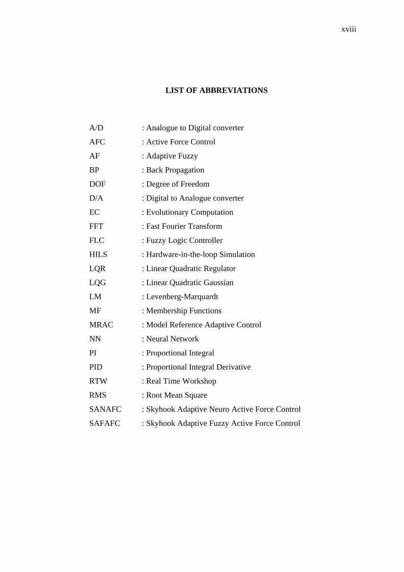
LIST OF ABBREVIATIONS
A/D : Analogue to Digital converter
AFC : Active Force Control
AF : Adaptive Fuzzy
BP : Back Propagation
DOF : Degree of Freedom
D/A : Digital to Analogue converter
EC : Evolutionary Computation
FFT : Fast Fourier Transform
FLC : Fuzzy Logic Controller
HILS : Hardware-in-the-loop Simulation
LQR : Linear Quadratic Regulator
LQG : Linear Quadratic Gaussian
LM : Levenberg-Marquardt
MF : Membership Functions
MRAC : Model Reference Adaptive Control
NN : Neural Network
PI : Proportional Integral
PID : Proportional Integral Derivative
RTW : Real Time Workshop
RMS : Root Mean Square
SANAFC : Skyhook Adaptive Neuro Active Force Control
SAFAFC : Skyhook Adaptive Fuzzy Active Force Control
xix
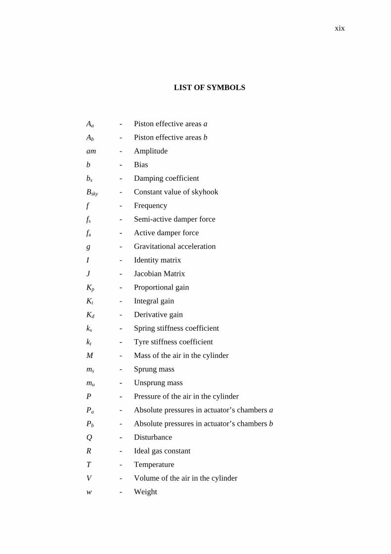
LIST OF SYMBOLS
Aa - Piston effective areas a
Ab - Piston effective areas b
am - Amplitude
b - Bias
bs - Damping coefficient
Bsky - Constant value of skyhook
f - Frequency
fs - Semi-active damper force
fa - Active damper force
g - Gravitational acceleration
I - Identity matrix
J - Jacobian Matrix
Kp - Proportional gain
Ki - Integral gain
Kd - Derivative gain
ks - Spring stiffness coefficient
kt - Tyre stiffness coefficient
M - Mass of the air in the cylinder
ms - Sprung mass
mu - Unsprung mass
P - Pressure of the air in the cylinder
Pa - Absolute pressures in actuator’s chambers a
Pb - Absolute pressures in actuator’s chambers b
Q - Disturbance
R - Ideal gas constant
T - Temperature
V - Volume of the air in the cylinder
w - Weight
xx
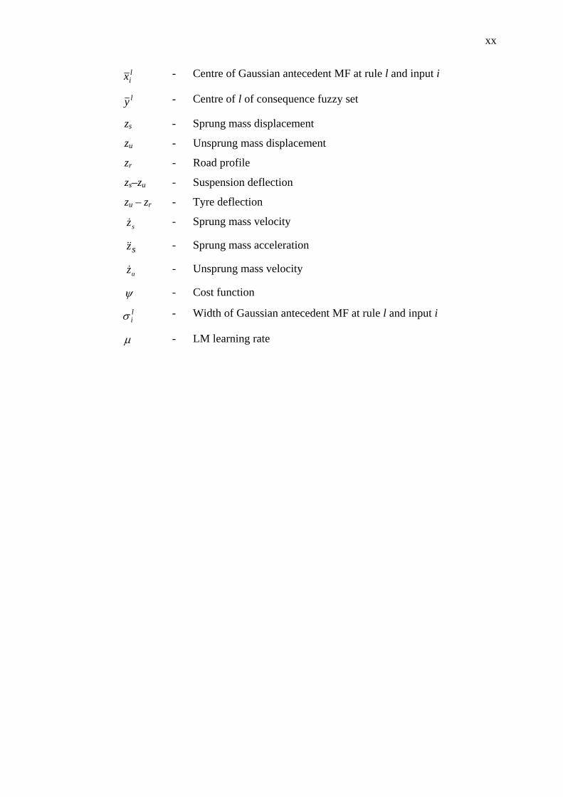
lix - Centre of Gaussian antecedent MF at rule l and input i
ly - Centre of l of consequence fuzzy set
zs - Sprung mass displacement
zu - Unsprung mass displacement
zr - Road profile
zs–zu - Suspension deflection
zu – zr - Tyre deflection
sz& - Sprung mass velocity
sz&& - Sprung mass acceleration
uz& - Unsprung mass velocity
ψ - Cost function
liσ - Width of Gaussian antecedent MF at rule l and input i
μ - LM learning rate
xxi
LIST OF APPENDICES
APPENDIX TITLE
PAGE
A List of Publications 154
B Results for the SAFAFC Scheme Subjected to Various 156
Road Disturbances
C Results for the Practical Implementation of the 168
SANAFC Scheme
CHAPTER 1
INTRODUCTION
1.1 Introduction
A suspension system is one of the essential components of any vehicle that
carries passenger in its body compartment. It is primarily used to provide the
absorption and/or isolation of undesirable vibration and load in the event the vehicle
travels on a rough road, thereby, providing some comfort to the passenger in the
vehicle (Ellis, 1994). Most vehicle suspension systems are typically made-up of a
spring and a shock absorber. When a car hits a bump or a hole, the spring is used to
temporarily store the energy generated by the disturbance force and resist the motion
that tends to change the car body height level. The shock absorber acts to quickly
dissipate the energy stored in the spring and damp out the vibration. Without the
shock absorber, the spring will cause the vehicle to vibrate continuously over a
certain period of time after the tyre passes over a bump or a hole. Darling and Dorey
(1992); Ellis (1994) outlined the requirements for a suspension system as follows:
1. Isolate the passenger from the road irregularities (ride)
2. Maintain contact between the tyre and the road
3. Provide safe handling during manoeuvres
4. React to changes in the load
5. Contain the suspension displacements within the limits of travel
6. Provide control over the pitch and roll motion of the vehicle body.
Thus, it can be deduced that the purpose of a suspension system is to minimize the
undesired motions during driving (Darling and Dorey, 1992).
2
1.2 Research Background
The main idea of a suspension system is to absorb the shock caused by the
irregularities on a road surface. Ideally, the suspension should isolate the body from
road and inertial disturbances that are typically associated with the acts of cornering
and braking or acceleration. In addition, the suspension must also be able to
minimize the vertical force transmitted to the passengers of the vehicle for their
comfort. This objective can be directly achieved by minimizing the vertical car body
acceleration. In any vehicle suspension system, there are a number of performance
parameters that need to be optimized to achieve acceptable specification and
compromise in ride comfort performance. In literature, the important parameters are
(Gaoa et al., 2006; Gillespie, 1992; Wong, 2001):
1. Body acceleration
Ride comfort is related to the acceleration sensed by passenger in the
vehicle when passing over a rough road surface. It is well-known that ride
comfort is an important performance specification for vehicle design,
which is typically evaluated by the body acceleration in the vertical
direction. Therefore, one of the main objectives in controller design is to
minimize the vertical body acceleration.
2. Tyre deflection
Tyre deflection can be attributed to the contact between the tyre and road
surface. In order to ensure a firm uninterrupted contact of the wheels to
the road surface, the dynamic tyre load should not exceed the static ones,
that is,
)(8.9)( usrut mmzzk +<− (1.1)
where ms, mu, kt, zs, zu, are the sprung mass, unsprung mass, tyre stiffness,
displacement of the sprung mass, displacement of unsprung mass,
respectively.
3. Suspension deflection
It refers to the relative displacement between the sprung mass (body) and
the unsprung mass (wheel). Because of the mechanical structure
3
constraint, the maximum allowable suspension stroke should be taken
into consideration to avoid excessive suspension bottoming, which can
possibly result in deterioration of the ride comfort and even structural
damage.
4. Actuator saturation
Saturation effect of actuator should be taken into account in view of the
limited power of the actuator, implying that the active force for the
suspension system should be confined to a certain range, that is,
maxuu ≤ (1.2)
where u is the active force input of the suspension system.
It is well-known fact that improving the ride quality has always been one of
the objectives of vehicle manufacturers. When designing a standard passive
suspension system, the trade-offs mentioned above is made upfront (fixed)
depending on the types of applications and cannot be easily changed. To overcome
this seemingly complex problem, many researchers have studied, proposed and
implemented various semi-active and active vehicle suspension systems both
theoretically as well experimentally (Appleyard and Wellstead, 1995).
In the case of semi-active and active suspension systems, the trade-off
decisions can be usually changed in real-time as the system is in operation. A semi-
active suspension has the ability to change the damping characteristics of the shock
absorbers as in an electro-rheological or magneto-rheological damper. In an active
suspension system, a pneumatic or a hydraulic actuator is typically attached in
parallel with both a spring and a shock absorber in between the sprung and unsprung
masses. The main advantage of employing an active suspension is the associated
adaptation potential the system has where the suspension characteristic can be
adjusted in real-time while driving to match the profile of the road being traversed
(Cherry and Jones, 1995).
4
The use of pneumatic actuator as an active suspension device is a relatively
new concept and has not been thoroughly explored. Pneumatic actuators demonstrate
highly nonlinear characteristics due to the compressibility of air, friction and the
nonlinearity of the valves. Thus, they are traditionally used for simple position and
speed control applications in industry, automation, being a prime example. In recent
years, low cost microprocessors (microcontrollers) and pneumatic components are
available which make it possible to adopt a more complex control strategy in
pneumatic actuator system control (Wang et al., 2001). Hence, investigations have
been carried out, employing pneumatic actuators to accomplish a large number of
motion control tasks.
The intent of the study is an attempt to introduce a new robust control
strategy of a suspension system that is based on active force control (AFC) approach.
The AFC has been recognized to be simple, robust and effective compared with
conventional methods in controlling dynamical systems, both in theory as well as
practice (Hewit and Burdess, 1981; Mailah, 1998; Kwek et al., 2003; Mailah et al.,
2005). Thus, the research shall explore the possibility of improving the vehicle
suspension dynamic performance using an integrated robust control strategy
incorporating intelligent method. The main works of this study include the design of
the proposed controller based on a number of established control models, choice of
actuator system, AI technique and a number of loading conditions. The research is
performed, first through a numerical technique in the form of a rigorous computer
simulation and later, complemented by an experimental implementation of the
proposed control scheme on a physical quarter car suspension test rig. A quarter car
model is chosen as the main model to investigate the effectiveness of the active
suspension system due to the simplicity of the model and yet can capture many
important characteristics of the full model (Fischer and Isermann, 2004). Finally,
performance evaluation both in time and frequency domains is conducted to
scrutinize the potential benefits of the proposed active suspension system.
5
1.3 Problem Statements
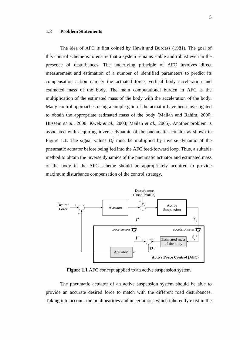
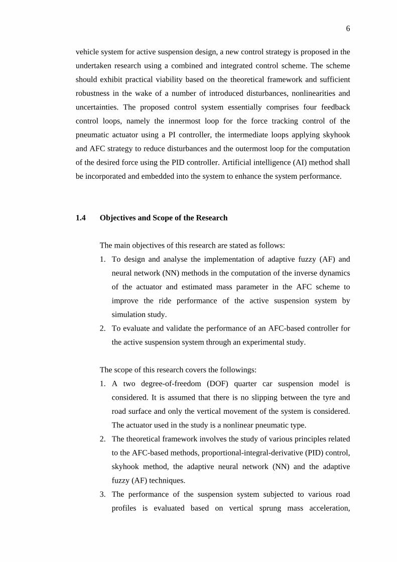
The idea of AFC is first coined by Hewit and Burdess (1981). The goal of
this control scheme is to ensure that a system remains stable and robust even in the
presence of disturbances. The underlying principle of AFC involves direct
measurement and estimation of a number of identified parameters to predict its
compensation action namely the actuated force, vertical body acceleration and
estimated mass of the body. The main computational burden in AFC is the
multiplication of the estimated mass of the body with the acceleration of the body.
Many control approaches using a simple gain of the actuator have been investigated
to obtain the appropriate estimated mass of the body (Mailah and Rahim, 2000;
Hussein et al., 2000; Kwek et al., 2003; Mailah et al., 2005). Another problem is
associated with acquiring inverse dynamic of the pneumatic actuator as shown in
Figure 1.1. The signal values Df′ must be multiplied by inverse dynamic of the
pneumatic actuator before being fed into the AFC feed-forward loop. Thus, a suitable
method to obtain the inverse dynamics of the pneumatic actuator and estimated mass
of the body in the AFC scheme should be appropriately acquired to provide
maximum disturbance compensation of the control strategy.
Actuator ActiveSuspension
+
Estimated massof the body
+ -
Actuator-1
Active Force Control (AFC)
Disturbance(Road Profile)
F
DesiredForce
force sensor accelerometer
'fD
sz&&+
++
'sz&&'F
Figure 1.1 AFC concept applied to an active suspension system
The pneumatic actuator of an active suspension system should be able to
provide an accurate desired force to match with the different road disturbances.
Taking into account the nonlinearities and uncertainties which inherently exist in the
6
vehicle system for active suspension design, a new control strategy is proposed in the
undertaken research using a combined and integrated control scheme. The scheme
should exhibit practical viability based on the theoretical framework and sufficient
robustness in the wake of a number of introduced disturbances, nonlinearities and
uncertainties. The proposed control system essentially comprises four feedback
control loops, namely the innermost loop for the force tracking control of the
pneumatic actuator using a PI controller, the intermediate loops applying skyhook
and AFC strategy to reduce disturbances and the outermost loop for the computation
of the desired force using the PID controller. Artificial intelligence (AI) method shall
be incorporated and embedded into the system to enhance the system performance.
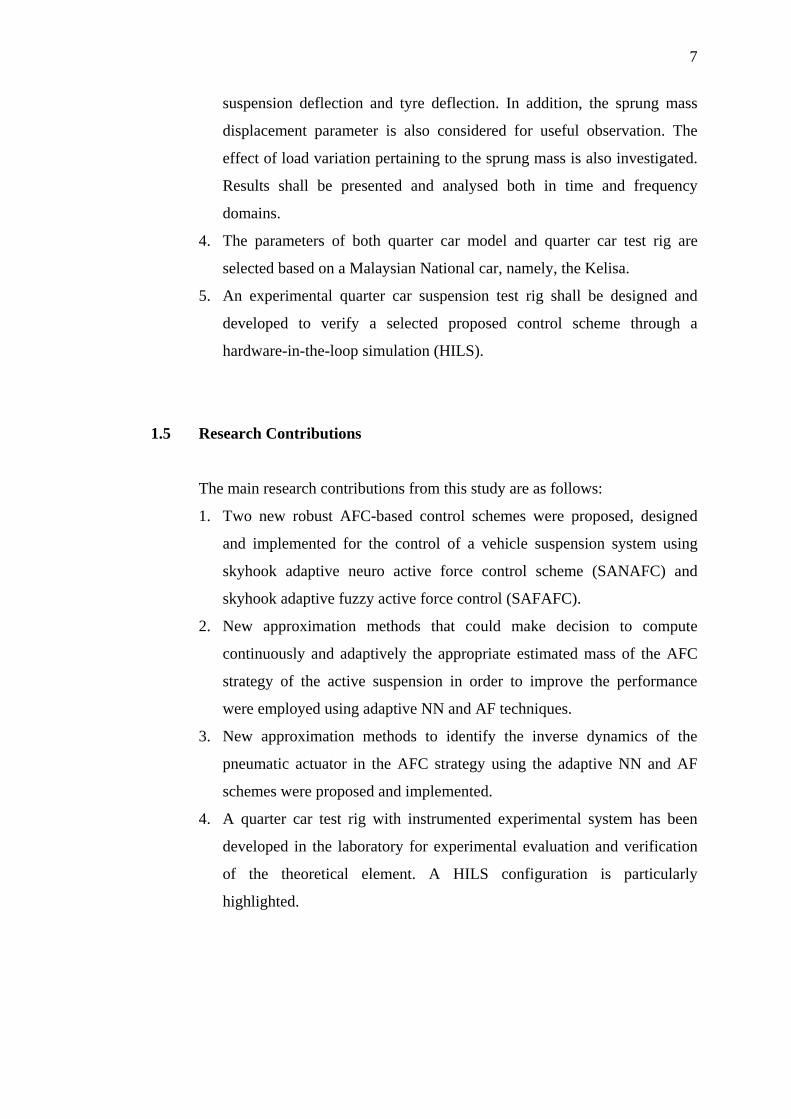
1.4 Objectives and Scope of the Research
The main objectives of this research are stated as follows:
1. To design and analyse the implementation of adaptive fuzzy (AF) and
neural network (NN) methods in the computation of the inverse dynamics
of the actuator and estimated mass parameter in the AFC scheme to
improve the ride performance of the active suspension system by
simulation study.
2. To evaluate and validate the performance of an AFC-based controller for
the active suspension system through an experimental study.
The scope of this research covers the followings:
1. A two degree-of-freedom (DOF) quarter car suspension model is
considered. It is assumed that there is no slipping between the tyre and
road surface and only the vertical movement of the system is considered.
The actuator used in the study is a nonlinear pneumatic type.
2. The theoretical framework involves the study of various principles related
to the AFC-based methods, proportional-integral-derivative (PID) control,
skyhook method, the adaptive neural network (NN) and the adaptive
fuzzy (AF) techniques.
3. The performance of the suspension system subjected to various road
profiles is evaluated based on vertical sprung mass acceleration,
7
suspension deflection and tyre deflection. In addition, the sprung mass
displacement parameter is also considered for useful observation. The
effect of load variation pertaining to the sprung mass is also investigated.
Results shall be presented and analysed both in time and frequency
domains.
4. The parameters of both quarter car model and quarter car test rig are
selected based on a Malaysian National car, namely, the Kelisa.
5. An experimental quarter car suspension test rig shall be designed and
developed to verify a selected proposed control scheme through a
hardware-in-the-loop simulation (HILS).
1.5 Research Contributions
The main research contributions from this study are as follows:
1. Two new robust AFC-based control schemes were proposed, designed
and implemented for the control of a vehicle suspension system using
skyhook adaptive neuro active force control scheme (SANAFC) and
skyhook adaptive fuzzy active force control (SAFAFC).
2. New approximation methods that could make decision to compute
continuously and adaptively the appropriate estimated mass of the AFC
strategy of the active suspension in order to improve the performance
were employed using adaptive NN and AF techniques.
3. New approximation methods to identify the inverse dynamics of the
pneumatic actuator in the AFC strategy using the adaptive NN and AF
schemes were proposed and implemented.
4. A quarter car test rig with instrumented experimental system has been
developed in the laboratory for experimental evaluation and verification
of the theoretical element. A HILS configuration is particularly
highlighted.
8
1.6 Organization of the Thesis
Chapter 2 presents the literature review on related subjects concerning this
thesis. In this chapter, the classification of vehicle suspension system, performance
index to be considered in suspension system design, properties of pneumatic
actuator, review on recently published articles related to pneumatic active suspension
control strategies and application of the active force control strategy are described.
In Chapter 3, the methodology of the research is presented. This methodology
is divided into a number of stages describing the corresponding tasks that need to be
carried out plus the tools that are associated with them. Essentially, there are two
main research activities to be accomplished, namely, the theoretical modelling and
simulation of the suspension system and the practical implementation of the
proposed methods for validation purpose.
Chapter 4 describes the general introduction and principle of adaptive fuzzy
system. Then, the simulation study of the new proposed scheme namely Skyhook
Adaptive Fuzzy Active Force Control (SAFAFC) is presented. The overall proposed
control system essentially comprises of four feedback control loops, namely the
innermost loop for force tracking of the pneumatic actuator performance using PI
controller, intermediate loops applying skyhook and AFC strategy for compensation
of the disturbances and outermost loop for the computation of the desired force using
PID controller. The parameter gains of PID controller are determined using Ziegler-
Nichols method. Adaptive fuzzy (AF) with back-propagation (BP) training
algorithms are used to approximate the inverse dynamic model of the pneumatic
actuator and to approximate the estimated mass in the AFC loop. Performance of the
suspension system is evaluated in terms of the sprung mass acceleration, sprung mass
displacement, suspension deflection and tyre deflection, both in time and frequency
domains. A measure of performance improvement has been included in this chapter
to benchmark all the five control schemes considered in the study.
Chapter 5 presents the simulation study of the new proposed scheme known
as Skyhook Adaptive Neuro Active Force Control (SANAFC). The structure of the
proposed controller is almost similar to that given in Chapter 4 in which it also
9
consists of four feedback control loops, but in this case, adaptive neural networks
(NN) are used to approximate the estimated mass and the inverse dynamics of the
pneumatic actuator. The adaptive NN uses modified Levenberg-Marqurdt (LM)
training algorithms. Performance of the suspension system is evaluated both in time
and frequency domains. Finally, the results of the proposed scheme are presented and
compared with those obtained using the SAFAFC method.
Chapter 6 describes the design and development of the experimental quarter
car suspension test rig that incorporates the proposed SANAFC scheme. Mechatronic
system design approach is adopted to realize the suspension test rig prototype. The
specifications of the active suspension system, PC-based controller and its
instrumentation system are described at length with particular emphasis on the
implementation of the HILS setting. The experimental results are presented both in
time and frequency domains and a comparative study is made between the proposed
SANAFC, PID controller and passive suspensions.
Chapter 7 discusses the differences that can be highlighted between the
simulation and experimental works that have been carried out in the research study.
The issues associated with implementing intelligent active force control on a quarter
car active suspension system using pneumatic actuator.
Finally, Chapter 8 concludes the research project. The directions and
recommendations for future research works are outlined. A list of publications
related to the study, relevant results from both simulation and experimental studies
are enclosed in the appendices.