universiti teknikal malaysia melaka...
TRANSCRIPT
UNIVERSITI TEKNIKAL MALAYSIA MELAKA
INVESTIGATION ON THE EFFECT OF HEAT TREATMENT
ON FRACTURE TOUGHNESS OF PRESURE VESSEL STEEL
This report submitted in accordance with the requirement of the Universiti Teknikal
Malaysia Melaka (Utem) for the Bachelor Degree of Manufacturing Engineering
(Engineering Materials) with Honours.
by
ISMAIL BIN BOLONG
FACULTY OF MANUFACTURING ENGINEERING
MEI 2009
i
ABSTRACT
Structural failure by fracture toughness in pressure vessel steel A516 Grade 70 of
low carbon steel can have severe consequences in term of heat treatment. Fracture
toughness KIC test is used to examine the toughness of each specimen after heat
treatment process done. In this research, the most common type of this term is
discussed and analyzed. The types of heat treatments that have been done like
tempering on 400oC, quenching in water, normalizing and full annealing. The
structural after heat treatment exposed to change the mechanical properties to this
material. Resulting from these changes affected the fracture toughness KIC value. The
methodologies were used such as Scanning Electron Machine and Axioscope Zeiss
Optical Microscope to examine the microstructure by 50x magnification. Vickers
Hardness and Tensile Test also were used to observe the mechanical properties of
each specimen. Fracture toughness KIC value is obtained by using Instron Machine.
As result, KIC graph show that tempering heat treatment make specimen tougher,
hard and high strength compare to full annealing, normalizing and base metal. But,
this specimen has low ductile and brittle.
ii
ABSTRAK
Kegagalan tanki keluli pada bahan A516 kelas 70 metal yang mempunyai karbon
yang rendah dapat dikesan daripada proses rawatan haba. Semua sampel yang telah
mengalami proses rawatan haba akan diuji untuk menentukan kekuatan bahan
tersebut daripada retak menggunakan ujian KIC. Dalam kajian yang telah dijalankan,
terdapat beberapa jenis rawatan haba yang telah dibuat ke atas bahan A516 kelas 70
seperti, pembajaan pada suhu 400 darjah celcius, sepuh lindap kejut menggunakan
air, penormalan dan juga penyepuhlindapan didalam relau. Hasil daripada rawatan
haba ini telah merubah struktur sampel dan juga sifat mekanikal. Seterusnya ini akan
memberi kesan terhadap perbezaan nilai kekuatan retakan KIC. Mesin Imbasan
Elektron dan Optik Mikroskop telah digunakan untuk melihat struktur dalaman pada
sampel. Nilai pembesaran yang digunakan untuk semua sampel adalah 50x0.70.
Mesin Instron pula digunakan untuk mendapatkan nilai kekuatan sampel yang
hendak diuji daripada retak. Ujian kekerasan dan juga ujian ketegangan turut
dijalankan untuk mengenalpasti sifat mekanikal yang terdapat pada sampel ini. Graf
KIC telah menunjukkan bahawa rawatan haba pembajaan telah menjadikan sampel
lebih kuat dan k eras berbanding yang lain. Namun begitu, rawatan jenis ini
membuatkan sampel lemah dari segi kelikatan dan rapuh apabila mencapai pada satu
tahap

iii
DEDICATION
I dedicate this report especially to UTeM, to my supervisor, to my parents
and my family. Never forget to my friends and to all people that help and support me
during my completion of this report.
iv
ACKNOWLEDGEMENT
For the first words in this research, I want to gratitude to god, most gracious and
merciful to show me guidance in accomplishing this research. Without His help and
consent, I could not finish this final year project based one. Actually this topic is
recommendation by one person where he is very interested and committed to know
something why the problem of this topic still happened until now. What I am learned
from this person, he didn’t never give up to give their supported, time spending,
knowledge about this project, guidance and what ever to ensure this research done
and achieve based on the objective in chapter 1. Million of thanks for everything and
a special acknowledgment for what I mean is Mr. Mohamad Haidir Bin Maslan as a
UTeM lecturer and also as a project supervisor. I wish to express my appreciation
also to Dr. Mohd Warikh Bin Abd Rashid as an examiner for guiding and sharing
some ideas for improve my project report.
In this opportunity also, my thanks to the UTeM technician who involved direct or
indirectly in assisting me start from coming material until the result of this
experiment obtained. Never forget to all library staff for their helping such as given
information to easy to find the manufacturing books, journal, ASTM standard and
what else I want to complete this research. Didn`t forget also to University
Technology Malaysia Skudai Johor (UTM) because of their cooperation to allowed
me to used their equipment like Instron Machine. The most important of my
appreciation is to my parents and family. Lastly to all my friends who give their
morale support and sharing this challenging time and beautiful life together.
v
TABLE OF CONTENTS
Abstract……………………………………………………………………………....i
Abstrak……………………………………………………………………………....ii
Dedication…………………………………………………………………………...iii
Acknowledgement…………………………………………………………………..iv
Table of Content………………………………………………………………….....v
List of Tables………………………………………………………………………viii
List of Figures………………………………………………………………………ix
List of Abbreviations………………………………………………………….…...xii
1. INTRODUCTION
1.1 Problem Statement…………………………………………………………..02
1.2 Objective…………………………………………………………………….03
1.3 Scope of Project……………………………………………………………..03
2. LITERATURE REVIEW
2.1 Introduction of Pressure Vessel Steel……………………………………… 04
2.2 Structural and Material Considerations………………….………………….05
2.3 Pressure Vessel Steel……………………………….………….....................06
2.3.1 ASTM A516 Grade 70 or ASME SA 516………………………………….07
2.4 Steels………………………………………………………………………...08
2.5 Heat Treatment……………………………………………………………...11
2.5.1 Objective of Heat Treatment………………………………………………..11
2.5.2 Principles of Heat Treatment of Steel………………………………………13
2.5.2.1 The Fe-C Phase Diagram……………………………………………………13
2.5.2.2 Transformation Diagrams…………………………………………………...20
2.5.2.3 Kinetics of Phase Transformations………………………………………….21
2.6 Types of Heat Treatment Steel……………………………………………...22
2.7 Introduction for Fracture Toughness………………………………………..29
2.7.1 General Fracture Toughness Behavior……………………………………....32
2.7.2 Types of Specimen Configuration…………………………………………..33
vi
2.8 Fracture Toughness Testing…………………………………………………34
2.8.1 Linear-Elastic Fracture Toughness………………………………………….35
2.9 Fracture Mechanics………………………………………………………….37
2.9.1 Linear-Elastic Fracture Mechanic…………………………………………...39
2.9.1.1 Crack Tip Stress………………………………………………………..........39
2.9.2 Pre-Cracking………………………………………………………………...41
3. METHODOLOGY
3.1 Introduction…………………………………………………………………43
3.2 Research and Design for This Project……………………………………….44
3.3 Sample Preparation………………………………………………………….45
3.4 Machining Equipment……………………………………………………….45
3.4.1 Contour Bent Saw Machine……………………………………………........46
3.4.2 Milling Machine……………………………………………………………..46
3.4.3 Wire EDM Cutting Machine…………………………………………….......48
3.5 Heat Treatment Process……………………………………………………..49
3.5.1 Austenite Treatment Phase …………………………………………………49
3.5.2 Tempering…………………………………………………………………...50
3.5.3 Quenching…………………………………………………………………...51
3.5.4 Annealing………………………………………………………………........52
3.5.5 Normalizing…………………………………………………………………52
3.6 Testing of Sample Material A516 Grade 70………………………………..53
3.6.1 Fracture Toughness ASTM 399-90…………………………………………53
3.6.1.1 Parameter of Jig, clip gauge (COD) and specimen…………………………54
3.6.2 Hardness Vickers Test………………………………………………………56
3.6.3 Microstructure Analysis……………………………………………..............57
3.6.4 Fractography Analysis………………………………………………………58
3.6.5 Tensile Test………………………………………………………………….60
4. RESULTS AND DISCUSSIONS
4.1 Tensile Result…………………………………………………………..........61
4.2 Heat Treatment………………………………………………………………62
4.1.1 Microstructure Analysis on Heat Treatment Process………………………..63
4.1.1.1 Base Metal A516 Grade 70 (low carbon steel)……………………………...63
vii
4.1.1.2 Tempering Result……………………………………………………………64
4.1.1.3 Quenching Result……………………………………………………………64
4.1.1.4 Full Annealing Result……………………………………………………….65
4.1.1.5 Normalizing Result………………………………………………………….65
4.3 Cracking Surface…………………………………………………………….66
4.4 Hardness Result……………………………………………………………..66
4.5 KIC Result……………………………………………………………………68
4.6 Fractograph Result…………………………………………………………..71
4.6.1 Scanning Electron Machine Analysis……………………………………….71
4.6.2 Comparison Structure……………………………………………………….72
5. CONCLUSIONS
5.1 Conclusion…………………………………………………………………..74
5.2 Recommendation……………………………………………………………75
REFERENCES 76
APPENDIX 79
A Gantt chart PSM I
B Planning Gantt chart PSM II
viii
LIST OF TABLES
TABLE TITLES PAGE
2.1 Composition range and limits for ASTM A 516 Grade 70 07
2.2 Mechanical properties and their application of structural steel 07
2.3 Material composition A516 Grade 70 as received 08
2.4 Oxide color for tempering steel 28
3.1 ASTM standard scale frequently 57
4.1 Stree vs Strain Graph 61
4.2 Stress vs Strain Parameter Obtained 62
4.3 Hardness Parameter 67
4.4 Kq Comparisons 71
ix
LIST OF FIGURES
FIGURE TITLES PAGE
2.1 Low carbon steel microstructure 09
2.2 High carbon steel microstructure 10
2.3 The Fe-C equilibrium diagram up to 6.67 wt% 14
2.4 Influence of alloying elements additions on eutectoid temperature and
eutectoid carbon content 16
2.5 Example of eutectic and eutectoid reactions in Fe-Fe3 C 16
2.6 Microstructure of eutectoid of steel (I) 17
2.7 Microstructure of eutectoid steel (II) 17
2.8 Microstructure of hypoeutectoid steel (I) 19
2.9 Microstructure of hypoeutectoid steel (II) 19
2.10 Microstructure of hypereutectoid steel (I) 19
2.11 Microstructure of hypereutectoid steel (II) 19
2.12 Kinetics of phase transformation 21
2.13 Full annealing graph 23
2.14 Time temperature regime of normalizing, a heating, b holding at
austenitizing temperature c air cooling d air or furnace cooling 24
2.15 Range of austenitizing temp for normalizing unalloyed steels depend on
their carbon content 24
2.16 Effect of grain refining by normalizing a carbon steel of 0.5C. Left side,
as-rolled or forged grain size ASTM 3 and right side normalized ASTM 6
magnification 500x 25
2.17 Transformation of a pearlitic structure to austenite when heating an
unalloyed eutectoid steel of 0.8 % C 26
2.18 Cup and cone ductile fracture of a tensile specimen 30
2.19 Longitudinal section of a tensile-strained specimen just prior to fracture 30
2.20 Stress vs strain graph 31
x
2.21a Flat R curve 32
2.21b Rising R curve 32
2.22 Compact test specimen for pin 0.24W (+0.000W / -0.005W) diameter 33
2.23a linear-elastic 34
2.23b Elastics-plastic (failure before limit load) 34
2.23c Fully plastic (exhibits a limit load) 34
2.24 ASTM E 399 compact specimen for fracture toughness testing 36
2.25 Typical load-versus-displacement record for the KIC test, two types. 37
2.26 Modes I (opening mode) 39
2.27 Modes I Crack 40
2.28a Test records 41
2.28b Heat-tinted fracture surface 41
2.28c J calculation 41
2.28d Resistance curve 41
2.29 Fatigue Pre-crack 42
3.1 Process flow chart 44
3.2 Material A516 Grade 70 45
3.3 Cutting area by using contour bent saw machine 46
3.4 Contour bent saw machine 46
3.5a Milling Machine 47
3.5b Surface Milling 47
3.5c Drilling 47
3.6a Wire EDM cutting area 48
3.6b Wire EDM cutting machine 49
3.7 Austenite graph 49
3.8 Tempering flow chart 50
3.9 Quenching flow chart 51
3.10 Full Annealing flow chart 52
3.11 Normalizing flow chart 53
3.12 Instron machine model 8800 54
3.13 Instron machine model 8802 54
3.14a Complete set jig with pin 55
3.14b Optical Telescope and specimen 55
xi
3.14c Clip gauge 55
3.14d COD displacement measurement 56
3.14e Compact test specimen 56
3.15 Hardness Vickers test machine 57
3.16 3% Nital solution 58
3.17 Axioscope Zeiss Optical Microscope 58
3.18a Scanning Electron Microscope 59
3.18b An example of fractographs, left side is brittle fracture 59
3.19 Tensile specimen 60
3.20 Universal Tensile Machine 60
4.1 Stress vs Strain Graph 61
4.2 Base Metal Microstructure 63
4.3 Tempering Microstructure 64
4.4 Quenching Microstructure 64
4.5 Full Annealing Microstructure 65
4.6 Normalizing Microstructure 65
4.7 Cracking Surface 66
4.8 Heat Treated Low Carbon Steel vs Hardness Vickers 67
4.9 KIC Base Metal Graph 68
4.10 KIC Full Annealing Graph 69
4.11 KIC Normalizing Graph 70
4.12 KIC Tempering Graph 70
4.13 Base Metal Structure 71
4.14 Full Annealing Structure 71
4.15 Normalizing Structure 72
4.16 Tempering Structure 72
4.17 Pre-Cracking Microstructure 72
4.18 Fracture Microstructure 73
xii
LIST OF ABBREVIATIONS AND SYMBOLS
ASTM - American Society for Testing and Materials
Al - Aluminium
AISI - American iron and steel institute
AC - Alternating current
BCC - Body centred cubic
BCT - Body centred tetragonal
BM - Base metal
CTOD - Crack-tip opening displacement
CGHAZ - Coarse-grained heat affected zone
C - Composition
CGB - Coarse-grained bainitic
CCT - Centre-cracked tension
Cr - Chromium
EDM - Electric discharge machining
EPFM - Elastic-plastic fracture mechanics
FCG Fatigue crack growth
FCC - Face centred cubic
FGB - Fine-grained bainitic
FGHAZ - Fine-grained heat affected zone
GDS - Glow Discharge Spectrometry
HAZ - Heat affected zone
ICR - Inter-critical region
K - Critical stress
K1 - Stress intensity factor
KC - Maximum fracture toughness
KIC - Fracture toughness
LEFM - Linear elastic fracture mechanics
LPG - Liquefied petroleum gas
Mo - Molybdenum
Mn - Magneseum
xiii
MPa - Mega pascal
Psig - Pound-force per square inch gauge
PWHT - Post weld heat treatment
SENT - Single edge notch tension
SENB - Single edge notch bend
SS - Stainless steel
Si - Silicon
Ti - Titanium
UNS - United Standard
WM - Weld metal
Zr - Zirconium
da/dN - Crack growth rate per cycle of loading
- Longitudinal stress
- Transverse stress
- Maximum stress
r - Radius
E - Young`s Modulus
a* - Effective crack length
rp - Circular plastic zone of radius
- Angular coordinate
- Torque stress
f - Residual stress
G - Energy release rate
γs - Specific surface energy
t - Thickness
a - Width and Length
- Work of plastic deformation
- Applied stress
- Crack length
- Elastic-plastic boundary
1
CHAPTER 1
INTRODUCTION
In this century, the world is more advanced together with turn of their rolling. These
phenomena show that the industry is increasing and alert for new-technologies.
Industries have now growing up caused of high demands on the quality of
engineering technology. An either obvious of one example am requesting on the use
of pressure vessels steel as autoclaves, boiler and others. This existed in all sector
industry to generate one product having quality and durable. Pressure vessels are one
device that it’s very synonyms for high temperatures. This is very sensitive area so
all factor fabrication of pressure vessels is not in consideration because it`s impact
involve deaths and priceless property damage. Therefore, these books publish to
investigate the fracture toughness of pressure vessel steel and relation on
microstructure
2
1.1 Problem Statement
The main topic of this research is about to investigate on the effect of heat treatment
on fracture toughness of pressure vessels steel. This research carried out base on still
equivalent has been problem rose in pressure vessels steel.
Cracking of internal surface in pressure vessels is very synonym happened but until
now to avoid this failure it`s still undergoing. Cracks will occur at welds and in the
HAZ of the weld and the crack will affect both parallel and transverse to the weld.
Cracking has occurred just after welding and as well as during the intended service
life. In particular, tensile residual stresses near the weld area may cause brittle
fracture, stress raisers, fatigue failure and stress corrosion cracking when exposed to
corrosive environments at certain temperature ranges [Challenger, N.V. 1995].
Semi-skilled or weaknesses during welding process is one of the critical failures in
pressure vessels. This problem such as brittle cracking in the heat-affected zone
(HAZ), often result from the use of steels containing excessive amounts of residual
elements that increase hardens ability and susceptibility to cracking. Steel sometimes
produced inadvertently when low-carbon steel is made in a furnace normally used to
make high-alloy steel. The refractory lining of the furnace may impart sufficient
residual chromium and other alloying elements to a heat of low-carbon steel that
problems occur when components made from that heat are joined using standard
welding procedures. Therefore, complete control of composition is of the almost
importance when welding is involved [Powel, G.W. 2002].
3
1.2 Objective
The overall objective of these researches is as follow;
i) To investigate the effect of heat treatment on fracture toughness of pressure
vessel steel
ii) To identify the fracture toughness on different microstructure.
1.3 Scope of the Project
The aimed of this research is to investigate the effect of heat treatment on fracture
toughness of pressure vessels steel for two different materials. The material that used
is from ASTM A516 Grade 70. Referring on ASTM standard, the properties of this
material is low-carbon. As mention in chapter 2 on literature review, the carbon
content of low-carbon steel is less 0.25% carbon. To ensure this research done with
their objective and scope, a few methods of heat treatment and also testing hardness
are used. On the heat treatment process this research used austenizing, annealing
normalizing, quenching and tempering. This research also covers the determination
of fracture toughness steel under predominantly linear-elastic fracture mechanic,
elastic-plastic fracture mechanic plane-strain conditions using fatigue pre-cracked,
Crack Tip Opening Displacement (CTOD) and KIC. The details of test apparatus,
specimen configuration, and experimental procedure are given based on ASTM
standard E 399-90.
4
CHAPTER 2
LITERATURE REVIEW
2.1 Introduction of Pressure Vessel
Vessels tanks, and pipelines that carry, store, or receive fluids are called pressure
vessels. A pressure vessel is defined as a container with a pressure differential
between inside and outside. The inside pressure is usually higher than the outside,
except for some isolated situations. The fluid inside the vessel may undergo a change
in state as in the case of steam boilers, or may combine with other have a
combination of high pressures together with high temperatures, and in some cases
flammable fluids or highly radio active material. Because of such hazards it is
imperative that the design be such that no leakage can occur. In addition these
vessels have to be designed carefully to cope with the operating temperature and
pressure. It should be borne in mind that the rupture of pressure vessels has a
potential to cause extensive physical injury and property damage. Plant safety and
integrity are of fundamental concern in pressure vessel design and these of course
depend on the adequacy of design codes.
In other words of pressure vessel steel is a closed container designed to hold gases or
liquids at a pressure different from the ambient pressure. The end caps fitted to the
cylindrical body are called heads. The rules for pressure vessel are contained in the
American Society of Mechanical Engineers Boiler and Pressure Vessel Code
[Harvey, J.F. 1985]. Pressure vessels are used in a variety of applications. These
include the industry and the private sector. For examples of pressure vessels are;
autoclaves, storage tanks or oil refineries.
5
Large pressure vessels were invented during the industrial revolution, particularly in
England for making steam engines [Harvey, J.F. 1985]. Design and testing standards
came about after some large explosions lead to loss off life and a system of
certification and testing mutations.
Pressure vessels as components of a complete plant are designed to meet various
requirements as determined by the designers and analysis responsible for the overall
design. The first step in the designed procedure is to select the necessary relevant
information, establishing in this way a body of design requirements. Once the design
requirements have been established, suitable materials are selected and the specified
design code will give an allowable design or nominal stress that is used to dimension
the main pressure vessel thickness.
Generally, almost any material with good tensile properties that is chemically stable
in the chosen application can be employed. Many pressure vessels are made of steel.
To manufacture a spherical pressure vessel, forged parts would have to be welded
together. Some mechanical properties of steel are increased by forging, but welding
can sometimes reduce these desirable properties. In case of welding, in order to make
the pressure vessel meet international safety standards, carefully selected steel with a
high impact resistance and corrosion resistant material should also be used.
2.2 Structural and Material Considerations
The continued and prolonged use of pressure vessels for power generation, nuclear or
chemical reactions, industrial processing, and storage requires them to withstand
severe conditions of pressure, temperature, and other environments. Such
environmental conditions include corrosion, neutron irradiation, hydrogen
embrittlement, and so on. Pressure vessels are required to operate at a high
temperature range from as high as 600oC to as low as -20
oC, with design pressures as
high as 140 MPa. Some vessels are designed to carry noncorrosive fluids; while
others are designed to withstand harsh corrosive and highly radioactive
environments. The type of service, whether steady or cyclic, may also vary
considerably. For each set of operating parameters, the pressure vessels material may
6
be required to have certain properties. For example, operation at very low
temperatures would require the use of materials with high notch toughness, while
operation at high temperatures would require the use of materials with high creep
strength.
Apart from the mechanical properties, considerations on manufacturability,
commercial availability, as well as cost, has to be accounted for in the selection
process. From researcher the materials that are used in pressure vessel construction
are:
a) Steels
i) Nonferrous materials such as aluminum and copper
ii) Specialty metals such as titanium and zirconium
iii) Nonmetallic materials, such as, plastic, composites and concrete
iv) Metallic and nonmetallic protective coatings
b) The mechanical properties that generally are of interest are:
i) Yield strength
ii) Ultimate strength
iii) Reduction of area (a measure of ductility)
iv) Fracture toughness
v) Resistance to corrosion
2.3 Pressure Vessel Steel
For this research, the types of material that used as follow the ASTM standard
requirement. The material that will be used in this research is A516 Grade 70 or
ASME SA 516 (low-carbon steel)
7
2.3.1 ASTM A516 Grade 70 or ASME SA516
The grade of this material is one of the most popular steel grades in market. It is
primarily intended for use in welded pressure vessels where notch toughness is
important. It comes in four grades 55, 60, 65 & 70. These grades cover a range of
tensile strengths from 55 - 90 MPa and this versatility explains much of the
specification popularity. For material tested were an ASTM A516 grade 70 hot-
rolled steel of ferritic-perlitic structure is one of our most popular steels. The ASME
standard composition is as follows (dependent on grade).
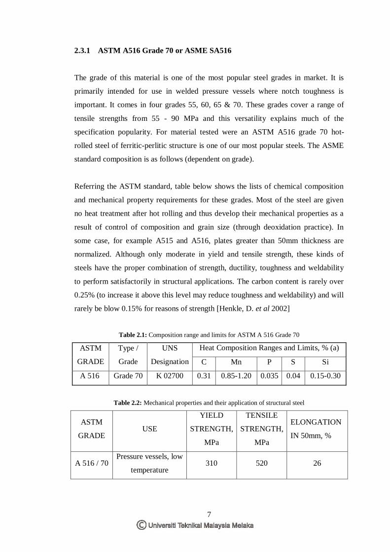
Referring the ASTM standard, table below shows the lists of chemical composition
and mechanical property requirements for these grades. Most of the steel are given
no heat treatment after hot rolling and thus develop their mechanical properties as a
result of control of composition and grain size (through deoxidation practice). In
some case, for example A515 and A516, plates greater than 50mm thickness are
normalized. Although only moderate in yield and tensile strength, these kinds of
steels have the proper combination of strength, ductility, toughness and weldability
to perform satisfactorily in structural applications. The carbon content is rarely over
0.25% (to increase it above this level may reduce toughness and weldability) and will
rarely be blow 0.15% for reasons of strength [Henkle, D. et al 2002]
Table 2.1: Composition range and limits for ASTM A 516 Grade 70
ASTM
GRADE
Type /
Grade
UNS
Designation
Heat Composition Ranges and Limits, % (a)
C Mn P S Si
A 516 Grade 70 K 02700 0.31 0.85-1.20 0.035 0.04 0.15-0.30
Table 2.2: Mechanical properties and their application of structural steel
ASTM
GRADE USE
YIELD
STRENGTH,
MPa
TENSILE
STRENGTH,
MPa
ELONGATION
IN 50mm, %
A 516 / 70 Pressure vessels, low
temperature 310 520 26