performance of four-stage cascaded fiber … · nisbah dan lebar jalur yang lebih baik jika peranti...
TRANSCRIPT
PERFORMANCE OF FOUR-STAGE CASCADED
FIBER OPTICAL PARAMETRIC AMPLIFIER
(FOPA) USING OPTISYSTEM
FATIN NABILAH BINTI MOHAMAD SALLEH
UNIVERSITI TUN HUSSEIN ONN MALAYSIA
PERFORMANCE OF FOUR-STAGE CASCADED FIBER OPTICAL
PARAMETRIC AMPLIFIER (FOPA) USING OPTISYSTEM
FATIN NABILAH BINTI MOHAMAD SALLEH
A thesis submitted in
fulfillment of the requirement for the award of the
Master of Electrical Engineering
Faculty of Electrical and Electronic Engineering
Universiti Tun Hussein Onn Malaysia
JULY, 2017

iii
To my beloved family
DEDICATION

iv
ACKNOWLEDGEMENT
Praise and thanks to Allah (SWT) who gave me the strength and courage to
complete this project.
I would like to express sincere thanks to my supervisor Dr. Nor Shahida Binti
Mohd Shah for her invaluable guidance throughout the course of this research. Her
guidance, ideas, encouragement, affable nature, kindness and support were greatly
helpful.
I would like to wish thanks to my mother Saidah Binti Hj Martan, for her daily
prayers and giving me motivation and strength. I also want to thank my late father,
Mohamad Salleh Bin Kassim for raising me up until his last breath. I will be ever
grateful for his assistance, and am sorry that he has not lived to witness my
achievements.
A special acknowledgment must be given to my brothers and sisters for their
support and help during my academic period at UTHM.
Finally, sincere gratitude to my friends who inspired me by their courage and
guidance throughout the period of my study.
v
ABSTRACT
An optical fiber plays a significant role to cater the increasing transmission capacity.
In optical fiber, there is a few nonlinear effects. One of the nonlinear effects is four-
wave mixing (FWM). In-depth analysis of FWM is conducted and it is found that one
of the applications in the FWM is a fiber optical parametric amplifier (FOPA). An
FOPA has an ability to achieve a high gain and bandwidth. One of the approaches is a
cascaded FOPA. A cascaded FOPA is a FOPA with two or more active media,
commonly known as a highly nonlinear fiber (HNLF). Previous experimental work
shows that the improvement in gain and bandwidth of the cascaded FOPA depends on
the passive or active devices inserted in between the HNLF. However, the results at
each stage of the cascaded FOPA are not discussed. The result at each stage is crucial
to ensure that the cascaded FOPA is amplifying power at the respective stage which is
the essence of this work. The cascaded FOPA is demonstrated by using an OptiSystem
software with four stages of HNLF with different parameters. Two research work
related to the cascaded FOPA are presented in this thesis. The first work focusses on
the effects of pump dithering to the cascaded FOPA, while the second work discusses
the effects of passive components to cascaded FOPA. The passive components
selected are isolator and optical bandpass filter (OBPF). The results show that the
FOPA with pump dithering can achieved the gain up to 27 dB, while without pump
dithering, only 9 dB gain is achieved. For the performance of the cascaded FOPA with
isolators, a high gain of 30 dB is obtained, while the cascaded FOPA with OBPFs, a
wider bandwidth of 36 nm is obtained. In conclusion, the pump dithering and isolator
can be used to achieved a high gain of FOPA and OBPF can be used to obtain a wider
bandwidth of FOPA.
vi
ABSTRAK
Gentian optik memainkan peranan yang penting bagi menampung peningkatan
kapasiti penghantaran. Terdapat beberapa jenis kesan tidak linear dalam gentian optik.
Salah satu kesan tidak linear tersebut ialah percampuran empat gelombang (FWM).
Kajian yang mendalam terhadap FWM telah dijalankan dan didapati bahawa FWM
mempunyai salah satu applikasi yang dikenali sebagai penguat parametrik gentian
optik (FOPA). FOPA mempunyai keupayaan untuk mencapai nisbah dan lebar jalur
yang tinggi. Salah satu pendekatan yang digunakan ialah lata FOPA. Lata FOPA
adalah FOPA dengan dua atau lebih aktif media, biasanya gentian silika amat tidak
linear (HNLF). Beberapa eksperimen lepas menunjukkan lata FOPA akan mempunyai
nisbah dan lebar jalur yang lebih baik jika peranti pasif atau aktif dimasukkan di antara
HNLF. Walau bagaimanapun, keputusan di setiap peringkat lata FOPA tidak
dibincangkan. Hasil disetiap peringkat adalah penting untuk memastikan bahawa lata
FOPA ditambah kuasa di setiap peringkat dan telah dikaji di dalam kajian ini. Dalam
kajian ini, simulasi lata FOPA dijalankan dengan menggunakan perisian OptiSystem
dengan empat peringkat HNLF yang mempunyai parameter berbeza. Dua kajian
penyelidikan berkaitan dengan lata FOPA secara simulasi telah ditunjukkan dalam
tesis ini. Kajian pertama memberi tumpuan kepada kesan penditeran pam terhadap lata
FOPA, manakala kajian kedua membincangkan kesan komponen pasif kepada lata
FOPA. Komponen pasif yang dipilih ialah pemencil dan tapis pita optik. Hasil kajian
menunjukan bahawa lata FOPA dengan penditeran pam mampu menjana gandaan
sehingga 27 dB, manakal tanpa pam penditeran hanya mampu mencapai gandaan
sebanyak 9 dB. Bagi prestasi lata FOPA bersama komponen pasif, pemencil berjaya
mendapat gandaan yang tinggi iaitu 30 dB manakala tapis pita optik berjaya
melebarkan lebar jalur lata FOPA sebanyak 36 nm. Konklusinya, penditeran pam dan
pemencil boleh digunakan bagi mendapatkan gandaan yang tinggi untuk FOPA dan
tapis pita optik mampu mendapatkan lebar jalur yang lebar.

vii
TABLE OF CONTENTS
DECLARATION ii
DEDICATION iii
ABSTRACT v
ABSTRAK vi
TABLE OF CONTENTS vii
LIST OF TABLES x
LIST OF FIGURES xi
LIST OF SYMBOLS AND ABBREVIATIONS xiii
LIST OF APPENDICES xvi
LIST OF PUBLICATIONS xvii
CHAPTER 1 INTRODUCTION 1
1.1 Preamble 1
1.2 Problem Background 2
1.3 Problem Statement 3
1.4 Research Objectives 3
1.5 Research Scopes 4
1.6 Report Outline 4
CHAPTER 2 LITERATURE REVIEW 5
2.1 Introduction 5
viii
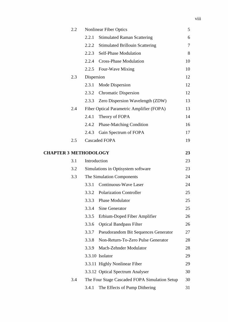
2.2 Nonlinear Fiber Optics 5
2.2.1 Stimulated Raman Scattering 6
2.2.2 Stimulated Brillouin Scattering 7
2.2.3 Self-Phase Modulation 8
2.2.4 Cross-Phase Modulation 10
2.2.5 Four-Wave Mixing 10
2.3 Dispersion 12
2.3.1 Mode Dispersion 12
2.3.2 Chromatic Dispersion 12
2.3.3 Zero Dispersion Wavelength (ZDW) 13
2.4 Fiber Optical Parametric Amplifier (FOPA) 13
2.4.1 Theory of FOPA 14
2.4.2 Phase-Matching Condition 16
2.4.3 Gain Spectrum of FOPA 17
2.5 Cascaded FOPA 19
CHAPTER 3 METHODOLOGY 23
3.1 Introduction 23
3.2 Simulations in Optisystem software 23
3.3 The Simulation Components 24
3.3.1 Continuous-Wave Laser 24
3.3.2 Polarization Controller 25
3.3.3 Phase Modulator 25
3.3.4 Sine Generator 25
3.3.5 Erbium-Doped Fiber Amplifier 26
3.3.6 Optical Bandpass Filter 26
3.3.7 Pseudorandom Bit Sequences Generator 27
3.3.8 Non-Return-To-Zero Pulse Generator 28
3.3.9 Mach-Zehnder Modulator 28
3.3.10 Isolator 29
3.3.11 Highly Nonlinear Fiber 29
3.3.12 Optical Spectrum Analyser 30
3.4 The Four Stage Cascaded FOPA Simulation Setup 30
3.4.1 The Effects of Pump Dithering 31
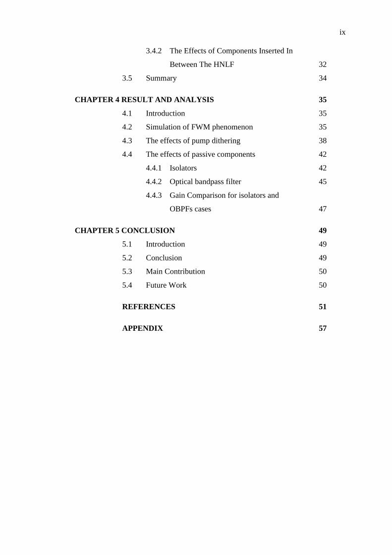
ix
3.4.2 The Effects of Components Inserted In
Between The HNLF 32
3.5 Summary 34
CHAPTER 4 RESULT AND ANALYSIS 35
4.1 Introduction 35
4.2 Simulation of FWM phenomenon 35
4.3 The effects of pump dithering 38
4.4 The effects of passive components 42
4.4.1 Isolators 42
4.4.2 Optical bandpass filter 45
4.4.3 Gain Comparison for isolators and
OBPFs cases 47
CHAPTER 5 CONCLUSION 49
5.1 Introduction 49
5.2 Conclusion 49
5.3 Main Contribution 50
5.4 Future Work 50
REFERENCES 51
APPENDIX 57
x
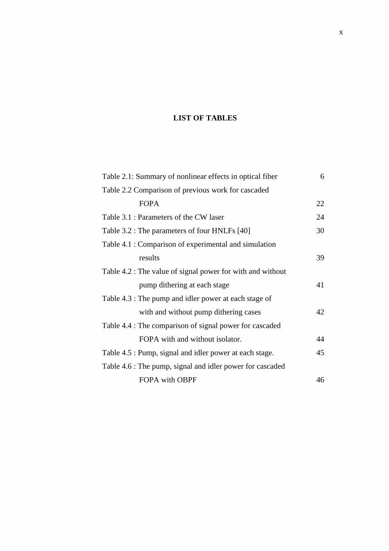
LIST OF TABLES
Table 2.1: Summary of nonlinear effects in optical fiber 6
Table 2.2 Comparison of previous work for cascaded
FOPA 22
Table 3.1 : Parameters of the CW laser 24
Table 3.2 : The parameters of four HNLFs [40] 30
Table 4.1 : Comparison of experimental and simulation
results 39
Table 4.2 : The value of signal power for with and without
pump dithering at each stage 41
Table 4.3 : The pump and idler power at each stage of
with and without pump dithering cases 42
Table 4.4 : The comparison of signal power for cascaded
FOPA with and without isolator. 44
Table 4.5 : Pump, signal and idler power at each stage. 45
Table 4.6 : The pump, signal and idler power for cascaded
FOPA with OBPF 46
xi
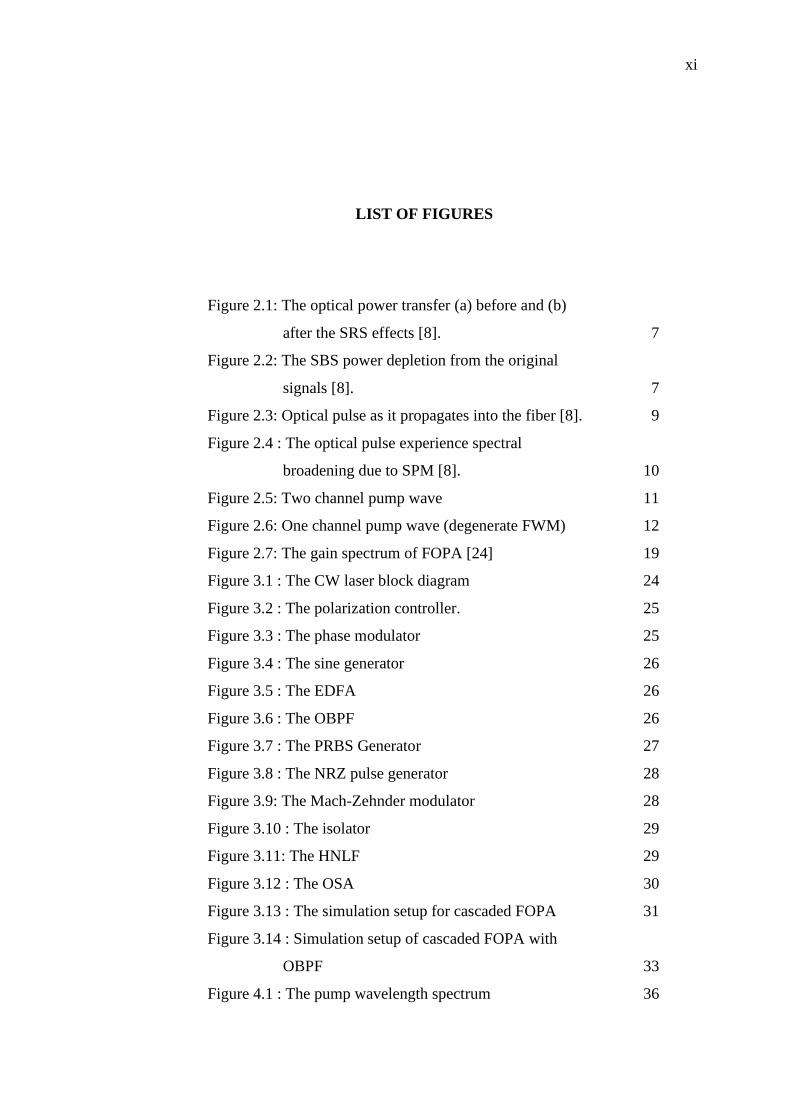
LIST OF FIGURES
Figure 2.1: The optical power transfer (a) before and (b)
after the SRS effects [8]. 7
Figure 2.2: The SBS power depletion from the original
signals [8]. 7
Figure 2.3: Optical pulse as it propagates into the fiber [8]. 9
Figure 2.4 : The optical pulse experience spectral
broadening due to SPM [8]. 10
Figure 2.5: Two channel pump wave 11
Figure 2.6: One channel pump wave (degenerate FWM) 12
Figure 2.7: The gain spectrum of FOPA [24] 19
Figure 3.1 : The CW laser block diagram 24
Figure 3.2 : The polarization controller. 25
Figure 3.3 : The phase modulator 25
Figure 3.4 : The sine generator 26
Figure 3.5 : The EDFA 26
Figure 3.6 : The OBPF 26
Figure 3.7 : The PRBS Generator 27
Figure 3.8 : The NRZ pulse generator 28
Figure 3.9: The Mach-Zehnder modulator 28
Figure 3.10 : The isolator 29
Figure 3.11: The HNLF 29
Figure 3.12 : The OSA 30
Figure 3.13 : The simulation setup for cascaded FOPA 31
Figure 3.14 : Simulation setup of cascaded FOPA with
OBPF 33
Figure 4.1 : The pump wavelength spectrum 36
xii
Figure 4.2 : The pump and signal wavelength after
injected into fiber 36
Figure 4.3 : The FWM phenomenon inside the optical
fiber 37
Figure 4.4 : The gain spectrum for simulation done and
experimental from [40] 38
Figure 4.5 : The signal powers at each stage of cascaded
FOPA without pump dithering 40
Figure 4.6 : The signal power at each stage of cascaded
FOPA with a pump dithering 41
Figure 4.7 : The gain spectrum for cascaded with and
without isolator. 43
Figure 4.8 : The signal power at each stage of cascaded
FOPA without isolator 44
Figure 4.9 : Output spectrum for each HNLFs of cascaded
FOPA with OBPFs 46
Figure 4.10: Gain spectrum for cascaded FOPA with
isolators and OBPFs. 48
xiii
LIST OF SYMBOLS AND ABBREVIATIONS
if - First optical frequency
jf - Second optical frequency
kf - Third optical frequency
ijkf - Fourth intermodulation product
1111 - Third-order nonlinear susceptibility
- Channel spacing
n - Fiber refractive index
𝒟 - Degeneracy factor
effL - Effective length
effA - Effective area
- Attenuation
L - Length
iP - Input power at if
jP - Input power at jf
kP - Input power at kf
ijkP - Power generated at ijkf
1p - Angular frequency of pump one
2p - Angular frequency of pump two
i - Angular frequency of idler
xiv
s - Angular frequency of signal
c - Center angular frequency
pP - Pump power
sP - Signal power
iP - Idler power
- Nonlinear coefficient
- Low propagation mismatch
p - Propagation constant of pump
s - Propagation constant of signal
i - Propagation constant of idler
c - Speed of light
o - Zero dispersion wavelength
p - Pump wavelength
s - Signal wavelength
i - Idler wavelength
dD
d - Slope of dispersion at zero dispersion wavelength
4 - Fourth-order dispersion coefficient
p - Phase of the pump
s - Phase of the signal
i - Phase of the idler
- Relative phase difference
- Phase-matching condition
M - Material dispersion
W - Waveguide dispersion
xv
NL - Nonlinear dispersion
G - Gain
expG - Exponential gain
quadG - Quadratic gain
DCF - Dispersion Compensation Fiber
DSF - Dispersion-Shifted Fiber
EDFA - Erbium Doped Fiber Amplifier
FBG - Fiber-Bragg Grating
FOPA - Fiber Optical Parametric Amplifier
FWM - Four-Wave Mixing
HNLF - Highly Nonlinear Fiber
OBPF - Optical Bandpass Filter
OOK - On-Off Keying
OSA - Optical Spectrum Analyzer
PC - Polarization Controller
PCF - Photonic Crystal Fiber
PIA - Phase-Insensitive Amplifier
PM - Phase Modulator
PSA - Phase-Sensitive Amplifier
QPM - Quasi-Phase Matching
RF - Radio Frequency
SBS - Stimulated Brillouin Scattering
SPM - Self-Phase Modulation
SRS - Stimulated Raman Scattering
SSMF - Standard Single-Mode Fiber
WDM - Wavelength Division Multiplexing
XPM - Cross-Phase Modulation
ZDW - Zero-Dispersion Wavelength
xvi
LIST OF APPENDICES
A The cascaded FOPA with pump dithering
setup 57
B The cascaded FOPA without pump dithering
setup 58
C Optisystem software setup for cascaded FOPA
without isolators 59
D Optisystem software setup for cascaded FOPA
with OBPFs 60
xvii
LIST OF PUBLICATIONS
Journal:
(i) F. N. Salleh, N. S. M. Shah, N. N. Shamsuddin, S. N. S. Yaacob, N. Othman,
“Cascaded Fiber Optical Parametric Amplifier with Isolators and Optical
Bandpass Filter using Optisystem.” International Journal of Simulation
Systems, Science and Technology.
Proceeding:
(i) F. N. Salleh, N. S. M. Shah, N. N. Shamsuddin, S. N. S. Yaacob, “The
Investigation on Fiber Optical Parametric Amplifier (FOPA) Bandwidth
using Optisystem.” Proceeding of The National Conference for Postgraduate
Research 2016 (NCON-PGR), UMP, 24-25 September 2016.
(ii) S. N. S. Yaacob, N. S. M. Shah, F. N. Salleh, “High Non-Linear Fiber Length
Verification in Optical Regeneration using Non-Return Zero and Return Zero
Signal.” Proceeding of The National Conference for Postgraduate Research
2016 (NCON-PGR), UMP, 24-25 September 2016.
(iii) F. N. Salleh, N. S. M. Shah, N. Othman, “The Effect of Pump Dithering on
Cascaded FOPA at Each Stage by Using Optisystem.” Proceeding of
International Conference on Electrical and Electronic Engineering 2017
(IC3E), Johor Bahru, 14-15 August 2017.
CHAPTER 1
INTRODUCTION
1.1 Preamble
In the past, the way people communicate with each other is different from what that
have been practiced today. Back then, most of the communication were realized via
voice, writing and signals.
The technology keeps evolving from the increasing demands. One of them is
the transfer of the information within the considerable distance. From the historical
point of view, the rapid growth of the electrical communication is the result of the
invention of the telegraph by Samuel F. B. Morse. The Morse code is represented by
letters and numbers with a series of dots and dashes. The major invention in
communication history is the discovery of the telephone in 1876 by Alexander Graham
Bell [1].
As time goes by, the increasing portion of the electromagnetic spectrum has
enhanced the medium of communication to be more reliable and has the ability to cater
the high capacity to convey messages from one place to another. Optical fiber is one
of the approaches to send messages via long distance transmission. The long-haul
transmission of data is not a problem to optical fiber because of the lower transmission
loss. Besides that, the low operation cost can be achieved by reducing the number of
repeaters. At the same time, the reduction of elements will reduce the complexity of
the systems. The optical fiber is also immune from the electromagnetic interference
since
2
it is made from dielectric materials. The demanding factor of high data rate application
is the reason wider bandwidth is needed. The optical fiber is the medium that can
realize that purpose.
The optical fiber itself experiences nonlinear effects that start to appear at the
increasing level of optical power. The nonlinear effects in an optical fiber are four-
wave mixing (FWM), cross-phase modulation (XPM), self-phase modulation (SPM),
stimulated Brillouin scattering (SBS) and stimulated Raman Scattering (SRS). In this
work, the focus is on the FWM nonlinearities.
Basically, FWM occurs when a light of two or more with different wavelengths
is launched into the optical fiber. When the lights are fed into the fiber, a new
wavelength will appear which is known as an idler [2]. The idler has a different
wavelength as compared to the light that is launched into the fiber. When the two
pumps of FWM have the same frequency, it is known as the degenerated FWM.
In the transmission of the wavelength-division multiplexing (WDM), FWM is
commonly avoided because it can cause crosstalk in the signal that is transmitted
through the optical fiber [3][4]. However, FWM is a practical technological basis for
certain applications. There are many applications for the FWM such as phase
conjugation, parametric amplification, wavelength conversion, ultrafast optical
sampling, optical switching and all-optical regeneration. In this research, attention is
diverted to the fiber optical parametric amplifier (FOPA). FOPA is an amplifier that
can have an amplification bandwidth outside Erbium Doped Fiber Amplifier (EDFA).
FOPA has a potential for amplification and wavelength conversion in multi-terabit/s
dense wavelength division multiplexing (DWDM). There are two types of FOPA
which are one-pump FOPA and two-pumps FOPA [5][6]. In this study, the one-pump
FOPA is chosen because of its simplicity. Besides that, FOPA can offer high gain and
low noise. However, narrow bandwidth of FOPA is the problem. Thus, in this work, a
method to obtain high gain with a wider bandwidth of FOPA is investigated.
1.2 Problem Background
The currents trends of FOPA demand a high gain and bandwidth. One of the
technique to achieved a high gain and wider bandwidth is by using a cascaded FOPA.
Cascaded FOPA is a concatenation technique of a few fibers that had been cut into
3
short pieces and been splice together. The cascaded FOPA is chosen due to its ability
to achieve a high gain or wider bandwidth depending on the components inserted in
between the two fibers. The latest trend involved a four-stage of cascaded FOPA and
show a reliable gain and bandwidth despite it splice loss [7].
However, the result at each stage is not presented. The result at each stage is
an added contribution towards the analysis. The spectrum at each stage of four-stage
cascaded FOPA is observed where the spectrum of pump, signal and idler light is
shown. The observation is focussed on the signal power due to it is related to the gain
and bandwidth. The observation at each stage of cascaded FOPA is quite complicated
to apply in the experimental work. This is one of the reason to conduct a simulation
and observing a spectrum at each stage of cascaded FOPA.
1.3 Problem Statement
The cascaded FOPA can increased the gain and bandwidth with an in-line of highly
nonlinear fiber (HNLF) configurations. A previous work has been conducted which
discussed the effects of passive devices that are added in between the HNLF. However,
the results at each stage of cascaded FOPA is not presented. The results at each stage
is crucial to ensure the cascaded FOPA runs successfully.
This work investigates the effects of components inserted at each stage on the
gain and bandwidth of cascaded FOPA. The in-depth study is also conducted at each
stage to observe the output spectrum of the cascaded FOPA.
1.4 Research Objectives
The objectives of this work are:
(i) To perform four-stage cascaded FOPA configurations.
(ii) To investigate the effects of pump dithering and inserted components towards
cascaded FOPA
(iii) To analyse the signal power at each stage of the four-stage cascaded FOPA
and the gain and bandwidth of the whole system.
4
1.5 Research Scopes
This research is conducted by using an Optisystem software. This four-stage
cascaded FOPA is only focused on the Non-Return to Zero-On Off Keying (NRZ-
OOK) modulation. Besides that, the inserted passive components chosen in this
research are isolators and optical bandpass filter (OBPF). However, there is a
limitation in the characterization at each stage of the four-stage cascaded FOPA. The
analysis only involves the value of signal powers at each stage because it related to the
gain and bandwidth. The bandwidth range involve in this research are from 1535 nm
until 1570 nm.
This research is not considering the splice loss of the four-stage concatenation
fiber. It also neglected the polarization and the phase of the pump and signal light.
1.6 Report Outline
This thesis consists of five (5) chapters. The introduction of this research is
discussed in Chapter 1. The literature review is elaborated in detail in Chapter 2. Next,
the methodology is being examined in Chapter 3. It described the method conducted
to achieve the objective in this study. Subsequently, the results of this study are
presented in Chapter 4 and the analysis towards the cascaded performance is discussed.
Lastly, the study is concluded in Chapter 5.
2CHAPTER 2
LITERATURE REVIEW
2.1 Introduction
This chapter describes the theoretical background of nonlinear effects and FWM
phenomenon. In addition, this chapter discusses the nonlinear fiber optics, dispersion,
phase matching, zero dispersion wavelength, fiber optic parametric amplifier (FOPA)
and cascaded FOPA.
2.2 Nonlinear Fiber Optics
Transmission of data in the optical fiber is a challenging process. One of the factors
that need to be considered is the nonlinear effects in the optical fiber. In the next
section, the nonlinear effects are discussed that include Stimulated Raman Scattering
(SRS), Stimulated Brillouin Scattering (SBS), Self-Phase Modulation (SPM),
Cross-Phase Modulation (XPM) and Four-Wave Mixing (FWM). The nonlinearities
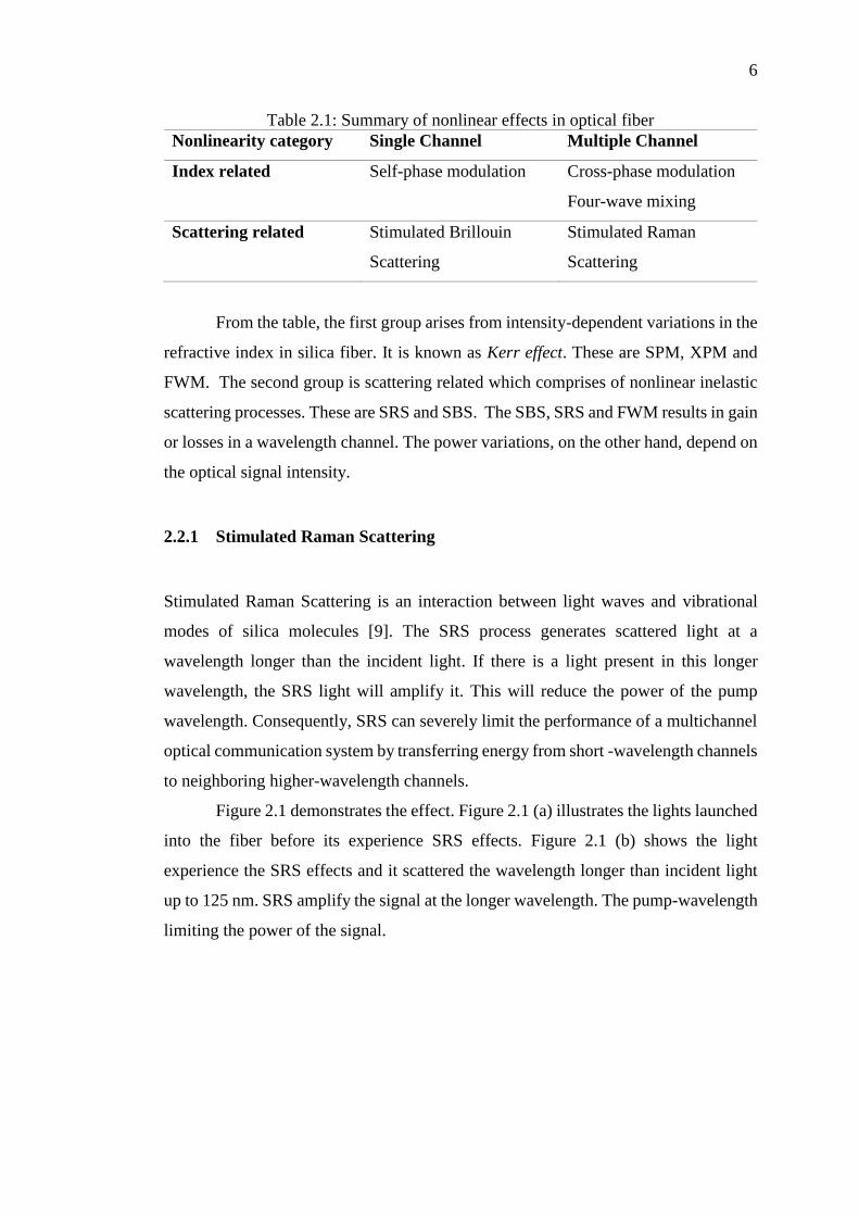
can be divided into two categories, which are summarized in Table 2.1 [8].
6
Table 2.1: Summary of nonlinear effects in optical fiber
Nonlinearity category Single Channel Multiple Channel
Index related Self-phase modulation Cross-phase modulation
Four-wave mixing
Scattering related Stimulated Brillouin
Scattering
Stimulated Raman
Scattering
From the table, the first group arises from intensity-dependent variations in the
refractive index in silica fiber. It is known as Kerr effect. These are SPM, XPM and
FWM. The second group is scattering related which comprises of nonlinear inelastic
scattering processes. These are SRS and SBS. The SBS, SRS and FWM results in gain
or losses in a wavelength channel. The power variations, on the other hand, depend on
the optical signal intensity.
2.2.1 Stimulated Raman Scattering
Stimulated Raman Scattering is an interaction between light waves and vibrational
modes of silica molecules [9]. The SRS process generates scattered light at a
wavelength longer than the incident light. If there is a light present in this longer
wavelength, the SRS light will amplify it. This will reduce the power of the pump
wavelength. Consequently, SRS can severely limit the performance of a multichannel
optical communication system by transferring energy from short -wavelength channels
to neighboring higher-wavelength channels.
Figure 2.1 demonstrates the effect. Figure 2.1 (a) illustrates the lights launched
into the fiber before its experience SRS effects. Figure 2.1 (b) shows the light
experience the SRS effects and it scattered the wavelength longer than incident light
up to 125 nm. SRS amplify the signal at the longer wavelength. The pump-wavelength
limiting the power of the signal.
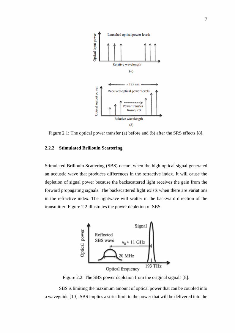
7
Figure 2.1: The optical power transfer (a) before and (b) after the SRS effects [8].
2.2.2 Stimulated Brillouin Scattering
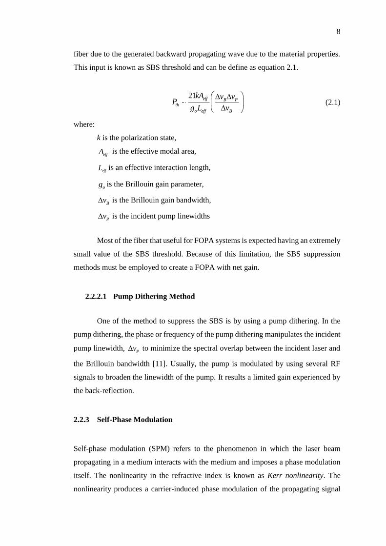
Stimulated Brillouin Scattering (SBS) occurs when the high optical signal generated
an acoustic wave that produces differences in the refractive index. It will cause the
depletion of signal power because the backscattered light receives the gain from the
forward propagating signals. The backscattered light exists when there are variations
in the refractive index. The lightwave will scatter in the backward direction of the
transmitter. Figure 2.2 illustrates the power depletion of SBS.
Figure 2.2: The SBS power depletion from the original signals [8].
SBS is limiting the maximum amount of optical power that can be coupled into
a waveguide [10]. SBS implies a strict limit to the power that will be delivered into the
8
fiber due to the generated backward propagating wave due to the material properties.
This input is known as SBS threshold and can be define as equation 2.1.
21 eff B P
th
o eff B
kA v vP
g L v
(2.1)
where:
k is the polarization state,
effA is the effective modal area,
effL is an effective interaction length,
og is the Brillouin gain parameter,
Bv is the Brillouin gain bandwidth,
Pv is the incident pump linewidths
Most of the fiber that useful for FOPA systems is expected having an extremely
small value of the SBS threshold. Because of this limitation, the SBS suppression
methods must be employed to create a FOPA with net gain.
2.2.2.1 Pump Dithering Method
One of the method to suppress the SBS is by using a pump dithering. In the
pump dithering, the phase or frequency of the pump dithering manipulates the incident
pump linewidth, Pv to minimize the spectral overlap between the incident laser and
the Brillouin bandwidth [11]. Usually, the pump is modulated by using several RF
signals to broaden the linewidth of the pump. It results a limited gain experienced by
the back-reflection.
2.2.3 Self-Phase Modulation
Self-phase modulation (SPM) refers to the phenomenon in which the laser beam
propagating in a medium interacts with the medium and imposes a phase modulation
itself. The nonlinearity in the refractive index is known as Kerr nonlinearity. The
nonlinearity produces a carrier-induced phase modulation of the propagating signal
9
which is known as Kerr effect. It will convert optical power fluctuations to spurious
phase fluctuations in the same waves.
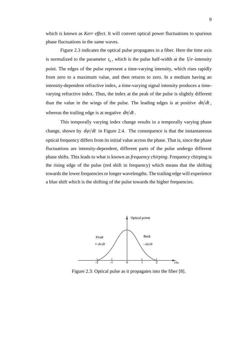
Figure 2.3 indicates the optical pulse propagates in a fiber. Here the time axis
is normalized to the parameter 0t , which is the pulse half-width at the 1 e -intensity
point. The edges of the pulse represent a time-varying intensity, which rises rapidly
from zero to a maximum value, and then returns to zero. In a medium having an
intensity-dependent refractive index, a time-varying signal intensity produces a time-
varying refractive index. Thus, the index at the peak of the pulse is slightly different
than the value in the wings of the pulse. The leading edges is at positive dn dt ,
whereas the trailing edge is at negative dn dt .
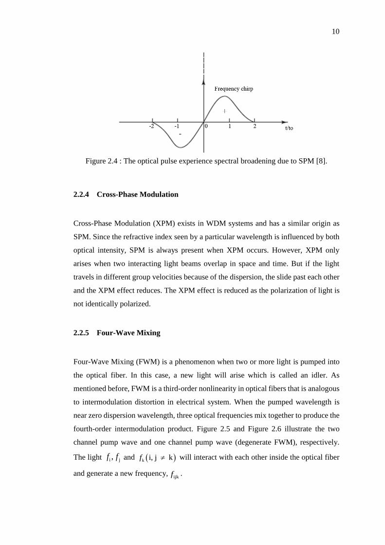
This temporally varying index change results in a temporally varying phase
change, shown by d dt in Figure 2.4. The consequence is that the instantaneous
optical frequency differs from its initial value across the phase. That is, since the phase
fluctuations are intensity-dependent, different parts of the pulse undergo different
phase shifts. This leads to what is known as frequency chirping. Frequency chirping is
the rising edge of the pulse (red shift in frequency) which means that the shifting
towards the lower frequencies or longer wavelengths. The trailing edge will experience
a blue shift which is the shifting of the pulse towards the higher frequencies.
Figure 2.3: Optical pulse as it propagates into the fiber [8].
10
Figure 2.4 : The optical pulse experience spectral broadening due to SPM [8].
2.2.4 Cross-Phase Modulation
Cross-Phase Modulation (XPM) exists in WDM systems and has a similar origin as
SPM. Since the refractive index seen by a particular wavelength is influenced by both
optical intensity, SPM is always present when XPM occurs. However, XPM only
arises when two interacting light beams overlap in space and time. But if the light
travels in different group velocities because of the dispersion, the slide past each other
and the XPM effect reduces. The XPM effect is reduced as the polarization of light is
not identically polarized.
2.2.5 Four-Wave Mixing
Four-Wave Mixing (FWM) is a phenomenon when two or more light is pumped into
the optical fiber. In this case, a new light will arise which is called an idler. As
mentioned before, FWM is a third-order nonlinearity in optical fibers that is analogous
to intermodulation distortion in electrical system. When the pumped wavelength is
near zero dispersion wavelength, three optical frequencies mix together to produce the
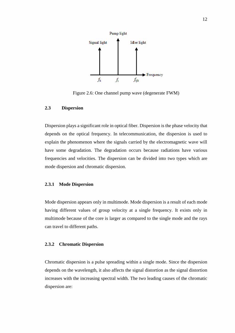
fourth-order intermodulation product. Figure 2.5 and Figure 2.6 illustrate the two
channel pump wave and one channel pump wave (degenerate FWM), respectively.
The light i j,f f and k i, j kf will interact with each other inside the optical fiber
and generate a new frequency,ijkf .
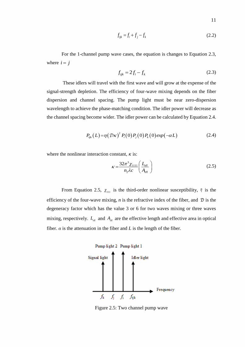
11
iij j kkf f f f (2.2)
For the 1-channel pump wave cases, the equation is changes to Equation 2.3,
where i j
2 iijk kf f f (2.3)
These idlers will travel with the first wave and will grow at the expense of the
signal-strength depletion. The efficiency of four-wave mixing depends on the fiber
dispersion and channel spacing. The pump light must be near zero-dispersion
wavelength to achieve the phase-matching condition. The idler power will decrease as
the channel spacing become wider. The idler power can be calculated by Equation 2.4.
2
ijk 0 0 0i j kP L P P P exp L (2.4)
where the nonlinear interaction constant, 𝜅 is:
3
eff1111
2 eff
32
L
n c A
(2.5)
From Equation 2.5, 1111 is the third-order nonlinear susceptibility, is the
efficiency of the four-wave mixing, n is the refractive index of the fiber, and 𝒟 is the
degeneracy factor which has the value 3 or 6 for two waves mixing or three waves
mixing, respectively. eff
L and eff
A are the effective length and effective area in optical
fiber. α is the attenuation in the fiber and L is the length of the fiber.
Figure 2.5: Two channel pump wave
12
Figure 2.6: One channel pump wave (degenerate FWM)
2.3 Dispersion
Dispersion plays a significant role in optical fiber. Dispersion is the phase velocity that
depends on the optical frequency. In telecommunication, the dispersion is used to
explain the phenomenon where the signals carried by the electromagnetic wave will
have some degradation. The degradation occurs because radiations have various
frequencies and velocities. The dispersion can be divided into two types which are
mode dispersion and chromatic dispersion.
2.3.1 Mode Dispersion
Mode dispersion appears only in multimode. Mode dispersion is a result of each mode
having different values of group velocity at a single frequency. It exists only in
multimode because of the core is larger as compared to the single mode and the rays
can travel to different paths.
2.3.2 Chromatic Dispersion
Chromatic dispersion is a pulse spreading within a single mode. Since the dispersion
depends on the wavelength, it also affects the signal distortion as the signal distortion
increases with the increasing spectral width. The two leading causes of the chromatic
dispersion are:
13
2.3.2.1 Material dispersion
Material dispersion is the variations of the refractive index of the core material as a
function of wavelength. Material dispersion is also known as chromatic dispersion in
which a prism spreads out the spectrum.
2.3.2.2 Waveguide dispersion
Waveguide dispersion effects pulse spreading because of the optical power
propagation is confined to the core. The wavelength will vary the distribution of the
light because of the cross-sectional of the core. It is the reason why the shorter
wavelengths are more confined to the center. The longer wavelengths will propagate
in the cladding. Waveguide dispersion can usually be ignored in multi-mode fibers,
but it is crucial in a single-mode fiber.
2.3.3 Zero Dispersion Wavelength (ZDW)
Zero dispersion wavelengths are the wavelength at which material dispersion and
chromatic dispersion will cancel each other and is equal to zero. The wavelength is
1300 nm for all silica-based optical fiber. For the dispersion shifted fibers, the zero
dispersion wavelengths are 1550 nm.
The phase matching is satisfied when the zero-dispersion wavelength is
positioned at the middle between the two lights. The phased match frequency
bandwidth is narrower for larger wavelength difference [2].
2.4 Fiber Optical Parametric Amplifier (FOPA)
Fiber optical parametric amplifier (FOPA) is one of the applications that is based on
the FWM. FOPA builds on the third-order Kerr nonlinearity of the optical fiber itself.
The higher value of nonlinearity coefficient, γ (about 5-10 times than conventional
fiber [12]) and high power of the input source are necessary to achieve the
amplification outside the Erbium Doped Fiber Amplifier (EDFA). Historically, the
14
first FOPA was demonstrated in 1976 by using low-loss fiber [13].The discovery of
EDFA in late 1980s has sparked the interest on FOPA. It has also contributed to the
development of dispersion-shifted fiber (DSF) with the zero-dispersion wavelength
(ZDW) at 1550 nm in the C-band area. The DSF with the highest value of γ has been
discovered in 1995 by increasing the germanium concentration and decreasing the core
diameter [14].
FOPA has been choosen as an amplifier because of its various advantages. One
of the benefits is it can avoid the degradation due to the chromatic dispersion since it
operates in the ZDW region. It also has low noise figure that can enhance the signal
amplification for long-haul communication. The most important factor is FOPA offers
wider bandwidth and high gain in phase-matching condition. The phase-matching
condition will be described later in this chapter. The research of FOPA has gained
more interest because of the adjustable center wavelength. This is due to the fact that
the Kerr nonlinearity varies slowly with wavelength. Thus, the parametric gain can
achieve the arbitrary wavelength. It also has the advantages of operating on the
(S-C-L) band wavelength [15]. Many features can be applied by using FOPA such as
wavelength conversion, phase conjugation and supercontinuum generation [16].
However, it has limited bandwidth and the methods to widen it have become a
significant interest.
2.4.1 Theory of FOPA
There are two types of FOPA which are One-Pump FOPA and Two-Pump FOPA. One
pump FOPA has a simple configuration as compared to the two-pump. However,
two-pump FOPA offers a wider bandwidth than one-pump FOPA[17].
As mentioned before, FOPA consists of one or two high power waves at
angular frequencies of 1p and
2p that will serve as the pump light sources. The new
wave at angular frequency, i will give rise to an idler. i will be generated at the
mirror image of the signal angular frequency, s where the signal input is the weak
signal that has been interacting with the pump light. Idler will be located at the center
wavelength, c which can be calculated by using Equation 2.6:
15
1 2c p p( ) / 2 , (2.6)
where 𝜔c is located at the halfway of pump 1 and pump 2 and can be simplified using
Equation 2.7:
s i c2 (2.7)
For one-pump FOPA, c is equal to the angular frequency of
pump source, 𝜔P . One pump FOPA is also known as degenerate FWM while the two-
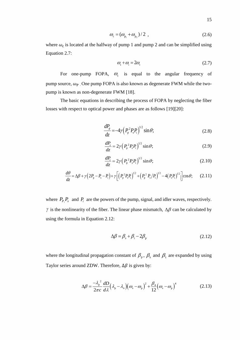
pump is known as non-degenerate FWM [18].
The basic equations in describing the process of FOPA by neglecting the fiber
losses with respect to optical power and phases are as follows [19][20]:
1/2p 2
p s i 4 sin ;dP
P PPdz
(2.8)
1 2
2sp s i2 sin ;
dPP PP
dz (2.9)
1 2
2ip s i2 sin ;
dPP PP
dz (2.10)
1 2 1 2 1 22 2
p s i p s i p s i s i2 4 cos ;d
P P P P PP P P P PPdz
(2.11)
where , sPP P and iP are the powers of the pump, signal, and idler waves, respectively.
is the nonlinearity of the fiber. The linear phase mismatch, can be calculated by
using the formula in Equation 2.12:
s i p2 (2.12)
where the longitudinal propagation constant of p , s and i are expanded by using
Taylor series around ZDW. Therefore, ∆𝛽 is given by:
2
2 4p 4p o s p s p
2 12
dD
c d
(2.13)
16
where:
c is the speed of light in vacuum,
o is the ZDW of the fiber used,
dD
d is the dispersion slope,
p is the pump wavelength,
4 is the fourth-order dispersion coefficient.
The relative phase difference between the waves is described as:
s i p s i2z z z z z z z (2.14)
where p z , s z and i z are the phases of the pump, signal and idler wave.
By referring to the Equation 2.8 to 2.11, the FOPA can be distinguished from
the phase-sensitive by controlling the phase relation, . By controlling the phase
relation, the direction of the power from the pump to the signal to the idler and vice
versa can be controlled. In addition, the signal can be attenuated or amplified by
controlling the phase relation. If 2 , this means that the parametric amplification
is occuring. The signal will be attenuated when 2 . It proves that FOPA can
be either a Phase-Insensitive Amplifier (PIA) or a Phase-Sensitive Amplifier (PSA).
2.4.2 Phase-Matching Condition
Phase-matching is defined as the balance between material dispersion, waveguide
dispersion and nonlinear dispersion [21]. By following the work in [22], it states that
the equation of phase-matching applies to the sum of the wavevectors of the different
waves participating in the process and can be written as:
M W NL (2.15)
17
where M , W and NL is material dispersion, waveguide dispersion and
nonlinear dispersion, respectively.
This condition can only be satisfied if one of the three dispersions is having a
negative value. M is in an anomalous dispersion regime. For single-mode fibers;
M is far less than W except for the region near the ZDW as the waveguide
dispersion and nonlinear dispersion can be adjusted to cancel the small dispersion.
In addition, FOPA must operate in a phase-matched condition. By following
the equations in 2.8 to 2.11; when 𝜃(𝑧) is in phase-matched condition, the value is
close to 2 . Thus, the third term in Equation 2.11 can be neglected and the
approximation in Equation 2.16 can be made [23]:
p s i p s i p2 2 2d
P P P P P P Pdz
(2.16)
where κ is the phase mismatch parameter.
The second approximation is only valid when the amplifier is operating in an
undepleted mode. The linear phase mismatch is crucial to achieve the broad bandwidth
of FOPA. The equation of the linear phase mismatch, shows that it is proportional
to the fiber dispersion slope. The small value of dispersion slope will enhance the
signal bandwidth further.
2.4.3 Gain Spectrum of FOPA
The gain of a parametric amplifier is dependent on the phase-matching condition. The
parametric gain is approximately exponentially proportional to the applied pump
power in the perfectly phase-matched condition.
In addition to the phase-matching, the gain value that can be attained is
dependent on the nonlinear phase shift in the fiber. It can be identified that in the ideal
case of perfect phase matching, where the relative phase is π/2, and does not change
during propagation; the growth of the gain is exponentially dependent on 2 PP L In
the absence of perfect phase matching, the change of the relative phase during
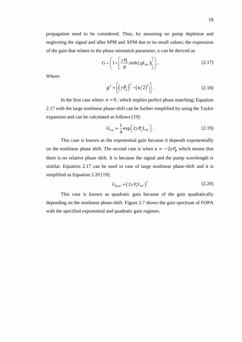
18
propagation need to be considered. Thus, by assuming no pump depletion and
neglecting the signal and idler SPM and XPM due to its small values; the expression
of the gain that relates to the phase mismatch parameter, κ can be derived as
Peff1 sinh
PG gL
g
, (2.17)
Where:
2 22
p 2g P
. (2.18)
In the first case where 0 , which implies perfect phase matching; Equation
2.17 with the large nonlinear phase-shift can be further simplified by using the Taylor
expansion and can be calculated as follows [19]:
exp p eff
1exp 2
4G P L . (2.19)
This case is known as the exponential gain because it depends exponentially
on the nonlinear phase shift. The second case is when 𝜅 = −2𝛾𝑃p which means that
there is no relative phase shift. It is because the signal and the pump wavelength is
similar. Equation 2.17 can be used in case of large nonlinear phase-shift and it is
simplified as Equation 2.20 [19]:
2
quad p eff2G P L (2.20)
This case is known as quadratic gain because of the gain quadratically
depending on the nonlinear phase-shift. Figure 2.7 shows the gain spectrum of FOPA
with the specified exponential and quadratic gain regimes.
19
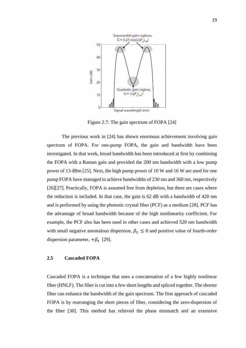
Figure 2.7: The gain spectrum of FOPA [24]
The previous work in [24] has shown enormous achievement involving gain
spectrum of FOPA. For one-pump FOPA, the gain and bandwidth have been
investigated. In that work, broad bandwidth has been introduced at first by combining
the FOPA with a Raman gain and provided the 200 nm bandwidth with a low pump
power of 13 dBm [25]. Next, the high pump power of 10 W and 16 W are used for one
pump FOPA have managed to achieve bandwidths of 230 nm and 360 nm, respectively
[26][27]. Practically, FOPA is assumed free from depletion, but there are cases where
the reduction is included. In that case, the gain is 62 dB with a bandwidth of 420 nm
and is performed by using the photonic crystal fiber (PCF) as a medium [28]. PCF has
the advantage of broad bandwidth because of the high nonlinearity coefficient. For
example, the PCF also has been used in other cases and achieved 520 nm bandwidth
with small negative anomalous dispersion, 𝛽2 ≤ 0 and positive value of fourth-order
dispersion parameter, +𝛽4 [29].
2.5 Cascaded FOPA
Cascaded FOPA is a technique that uses a concatenation of a few highly nonlinear
fiber (HNLF). The fiber is cut into a few short lengths and spliced together. The shorter
fiber can enhance the bandwidth of the gain spectrum. The first approach of cascaded
FOPA is by rearranging the short pieces of fiber, considering the zero-dispersion of
the fiber [30]. This method has relieved the phase mismatch and an extensive
20
conversion has been achieved. The cascaded FOPA is investigated from the Quasi-
phase matching (QPM) theory. The QPM is one of the techniques to mitigate the
phase-matching effect [31]. QPM technique has been applied to the slot waveguide to
alter the phase-mismatch to achieve the broadband wavelength conversion [32]. In
addition, the QPM has been implemented for transparent optical demultiplexer for
160 Gb/s – 10 Gb/s demultiplexer [33]. There is also an investigation conducted to
observe the modulation instability of the multisection fiber with a numerical
simulation of the nonlinear Schrodinger equation [34]. The design shows that the gain
spectrum bandwidth is exceeded by 100nm with a ripple and 200nm when a pump
power of 5 W is used.
Besides that, a dispersion compensation fiber (DCF) is placed in between the
two HNLF to compensate the HNLF dispersion [35][36].It is known as a periodic
compensation. The widest bandwidth is achieved by using three stages of HNLF with
a DCF. In the same way, the standard single-mode fiber (SSMF) is used to compensate
the dispersion [37]. The difference of dispersion parameter can relieve the phase
matching condition. The value of dispersion is set to get a high absolute value of 𝛽2
that would lead to a high linear phase mismatch and eventually can compensate the
HNLF dispersion and improve the gain. The performance is examined by observing
each stage.
The cascaded FOPA can be analysed by using genetic algorithm [38][39]. The
cascaded FOPA can also be done by rearranging the fiber and putting the isolators in
between the HNLF [40]. The isolators have the ability to suppress the SBS effect [41].
Meanwhile, the highest gain achieved by the two-segment FOPA with an isolator is
60 dB [7]. The gain smoothened with a two-segment has been discussed before by
using the idler removal filter to achieve the dispersion mismatch [42].
An optical bandpass filter (OBPF) has also been used in cascaded FOPA [43].
The gain of FOPA is enhanced as compared to the gain without an OBPF. The pump
shifters have also been used in the cascaded FOPA where a gain of 21dB has been
achieved with a gain flatness bandwidth of 25 nm [44]. Other than that, the cascaded
FOPA with a phase shifter has widened the bandwidth from 9 nm to 30 nm [45]. Fiber-
Bragg grating (FBG) can enhance the bandwidth when it is used in the cascaded
configuration [46]. The cascaded FOPA with a FBG has achieved a 22-dB gain with a
50 nm bandwidth of gain flatness [47].
21
Cascaded FOPA without any elements is an advantage in wavelength
conversion application. The previous work has achieved a 49 dB gain with 56 nm
bandwidth [48]. Additionally, the cascaded FOPA can be used for
polarization-insensitive configuration [49]. The advantages of cascaded FOPA over
the polarization-insensitive configuration is the arbitrary input or output operation
wavelength and the signal transparency. Moreover, the cascaded structure has an
ability to obtain the PSA and PIA [50]. PSA has achieved the bandwidth of 170 nm
while the PIA has reached 160 nm. It is considered significant as compared to the
conventional PSA and PIA. Besides that, the SMF and DCF have been placed in
between PIA and PSA segments to achieve power equalization and the gain bandwidth
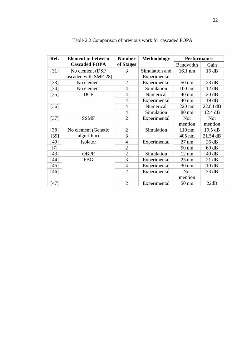
is broadened to 15 nm [51]. Table 2.2 shows the previous work of cascaded FOPA.
From the table below, the previous work has been focusing on the gain and
bandwidth because they are the most important parameters to measure the performance
of cascaded FOPA. However, because of the structure of the cascaded FOPA it which
has a few stages of HNLF, the spectrum at each stage needs to be observed to monitor
the changes at the respective stage. In this work, the characteristics at each stage are
observed. It is crucial as it is a lot easier to detect the problems from the stage by stage
basis.
22
Table 2.2 Comparison of previous work for cascaded FOPA
Ref. Element in between
Cascaded FOPA
Number
of Stages
Methodology Performance
Bandwidth Gain
[31] No element (DSF
cascaded with SMF-28)
3 Simulation and
Experimental
16.1 nm 16 dB
[33] No element 2 Experimental 50 nm 23 dB
[34] No element 4 Simulation 100 nm 12 dB
[35] DCF 4 Numerical 40 nm 20 dB
4 Experimental 40 nm 19 dB
[36] 4 Numerical 220 nm 22.84 dB
4 Simulation 80 nm 12.4 dB
[37] SSMF 2 Experimental Not
mention
Not
mention
[38] No element (Genetic
algorithm)
2 Simulation 110 nm 10.5 dB
[39] 3 405 nm 21.54 dB
[40] Isolator 4 Experimental 27 nm 26 dB
[7] 2 50 nm 60 dB
[43] OBPF 2 Simulation 12 nm 40 dB
[44] FBG 3 Experimental 25 nm 21 dB
[45] 4 Experimental 30 nm 10 dB
[46] 2 Experimental Not
mention
33 dB
[47] 2 Experimental 50 nm 22dB
3CHAPTER 3
METHODOLOGY
3.1 Introduction
This chapter highlights the techniques and methods employed to study the
performance of a cascaded FOPA. The effects of pump dithering towards the cascaded
FOPA is investigated. Then, the effects of passive components towards the gain and
bandwidth are observed. The details of simulation work are also explained in this
chapter.
3.2 Simulations in Optisystem software
OptiSystem is a comprehensive software design suite that enables users to plan, test,
and simulate the optical links in the transmission layer of modern optical networks.
The simulations feature the result of each parameter that needs to be observed in this
work.
In this work, each layout can have certain component parameters assigned to
be in a sweep mode. The number of sweep iterations to be performed on the selected
parameters is defined beforehand. It is observed that at the value of the parameters
changes at each sweep of iterations which produces a series of different calculation
results.
24
3.3 The Simulation Components
The simulation is performed to observe the phenomenon of FWM inside the optical
fibers and the gain and bandwidth of the four stages of cascaded FOPA. Besides that,
the output at each stage of cascaded FOPA is observed to monitor the signal power.
The cascaded FOPA setup includes the optical sources, optical amplifier,
optical filter, modulation and visual analyzer. Each of the components is discussed in
the following section.
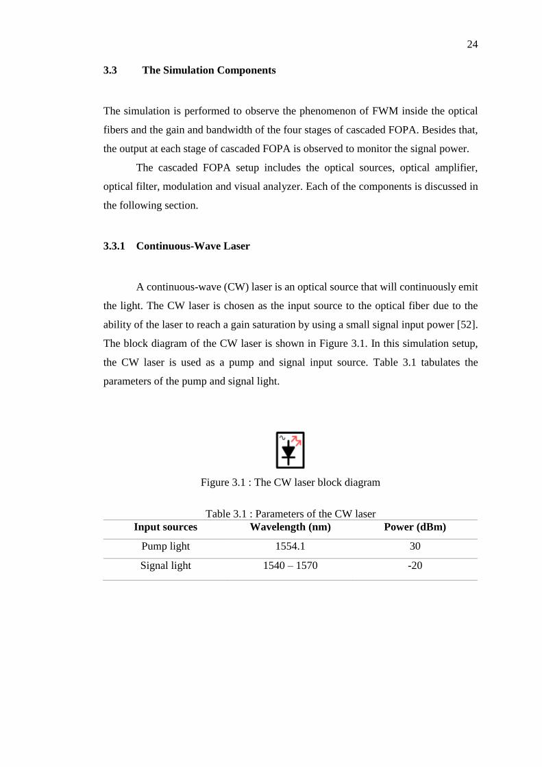
3.3.1 Continuous-Wave Laser
A continuous-wave (CW) laser is an optical source that will continuously emit
the light. The CW laser is chosen as the input source to the optical fiber due to the
ability of the laser to reach a gain saturation by using a small signal input power [52].
The block diagram of the CW laser is shown in Figure 3.1. In this simulation setup,
the CW laser is used as a pump and signal input source. Table 3.1 tabulates the
parameters of the pump and signal light.
Figure 3.1 : The CW laser block diagram
Table 3.1 : Parameters of the CW laser
Input sources Wavelength (nm) Power (dBm)
Pump light 1554.1 30
Signal light 1540 – 1570 -20
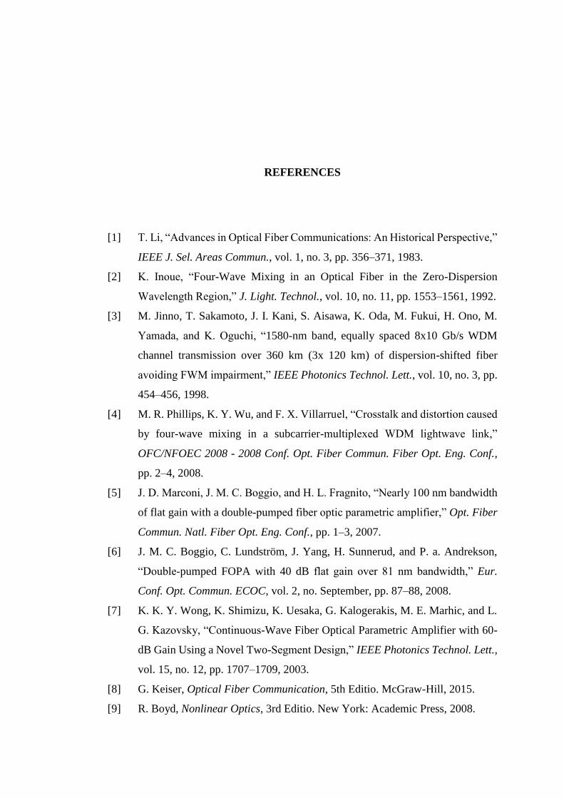
REFERENCES
[1] T. Li, “Advances in Optical Fiber Communications: An Historical Perspective,”
IEEE J. Sel. Areas Commun., vol. 1, no. 3, pp. 356–371, 1983.
[2] K. Inoue, “Four-Wave Mixing in an Optical Fiber in the Zero-Dispersion
Wavelength Region,” J. Light. Technol., vol. 10, no. 11, pp. 1553–1561, 1992.
[3] M. Jinno, T. Sakamoto, J. I. Kani, S. Aisawa, K. Oda, M. Fukui, H. Ono, M.
Yamada, and K. Oguchi, “1580-nm band, equally spaced 8x10 Gb/s WDM
channel transmission over 360 km (3x 120 km) of dispersion-shifted fiber
avoiding FWM impairment,” IEEE Photonics Technol. Lett., vol. 10, no. 3, pp.
454–456, 1998.
[4] M. R. Phillips, K. Y. Wu, and F. X. Villarruel, “Crosstalk and distortion caused
by four-wave mixing in a subcarrier-multiplexed WDM lightwave link,”
OFC/NFOEC 2008 - 2008 Conf. Opt. Fiber Commun. Fiber Opt. Eng. Conf.,
pp. 2–4, 2008.
[5] J. D. Marconi, J. M. C. Boggio, and H. L. Fragnito, “Nearly 100 nm bandwidth
of flat gain with a double-pumped fiber optic parametric amplifier,” Opt. Fiber
Commun. Natl. Fiber Opt. Eng. Conf., pp. 1–3, 2007.
[6] J. M. C. Boggio, C. Lundström, J. Yang, H. Sunnerud, and P. a. Andrekson,
“Double-pumped FOPA with 40 dB flat gain over 81 nm bandwidth,” Eur.
Conf. Opt. Commun. ECOC, vol. 2, no. September, pp. 87–88, 2008.
[7] K. K. Y. Wong, K. Shimizu, K. Uesaka, G. Kalogerakis, M. E. Marhic, and L.
G. Kazovsky, “Continuous-Wave Fiber Optical Parametric Amplifier with 60-
dB Gain Using a Novel Two-Segment Design,” IEEE Photonics Technol. Lett.,
vol. 15, no. 12, pp. 1707–1709, 2003.
[8] G. Keiser, Optical Fiber Communication, 5th Editio. McGraw-Hill, 2015.
[9] R. Boyd, Nonlinear Optics, 3rd Editio. New York: Academic Press, 2008.
52
[10] Michel E. Marhic, Fiber optical parametric amplifiers, oscillators, and related
devices. Cambridge University Press, 2007.
[11] J. B. Coles, B. P.-P. Kuo, N. Alic, S. Moro, C.-S. Bres, J. M. Chavez Boggio,
P. a Andrekson, M. Karlsson, and S. Radic, “Bandwidth-efficient phase
modulation techniques for stimulated Brillouin scattering suppression in fiber
optic parametric amplifiers.,” Opt. Express, vol. 18, no. 17, pp. 18138–18150,
2010.
[12] M. Onishi, T. Okuno, T. Kashiwada, S. Ishikawa, N. Akasaka, and M.
Nishimura, “Highly Nonlinear Dispersion-Shifted Fibers and Their Application
to Broadband Wavelength Converter,” Opt. Fiber Technol., vol. 4, no. 2, pp.
204–214, 1998.
[13] R. H. Stolen and W. N. Leibolt, “Optical fiber modes using stimulated four
photon mixing.,” Appl. Opt., vol. 15, no. 1, pp. 239–243, 1976.
[14] M. J. Holmes, D. L. Williams, and R. J. Manning, “Highly nonlinear optical
fiber for all optical processing\napplications,” IEEE Photonics Technol. Lett.,
vol. 7, no. 9, pp. 1045–1047, 1995.
[15] C. Floridia, M. L. Sundheimer, L. D. S. Menezes, and A. S. L. Gomes,
“Optimization of spectrally flat and broadband single-pump fiber optic
parametric amplifiers,” Opt. Commun., vol. 223, no. 4–6, pp. 381–388, 2003.
[16] C. W. Thiel, “Four-Wave Mixing and its Applications,” Citeseer, vol. 156, no.
3, pp. 1–19, 2008.
[17] H. Pakarzadeh, “Optimization of two-pump fiber optical parametric amplifiers
for broadband flat gain and low pump-to-signal noise transfer,” in Symposium
on Photonics and Optoelectronics, SOPO, 2012, no. 4, pp. 3–6.
[18] O. Aso, M. Tadakuma, and S. Namiki, “Four-wave mixing in optical fibers and
its applications,” Furukawa Rev., vol. 19, no. 19, pp. 63–68, 1999.
[19] J. Hansryd, P. A. Andrekson, M. Westlund, J. Li, and P. O. Hedekvist, “Fiber-
based optical parametric amplifiers and their applications,” IEEE J. Sel. Top.
Quantum Electron., vol. 8, no. 3, pp. 506–520, 2002.
[20] M. E. Marhic, Fiber Optical Parametric Amplifier, Oscillators and Related
Devices. Cambridge University Press; 1 edition (December 3, 2007), 2008.
[21] J. Toulouse, “Optical nonlinearities in fibers: Review, recent examples, and
systems applications,” Journal of Lightwave Technology, vol. 23, no. 11. pp.
3625–3641, 2005.
53
[22] G. P. Agrawal, Nonlinear fiber optics, 3rd Editio. 2001.
[23] R. Stolen and J. Bjorkholm, “Parametric amplification and frequency
conversion in optical fibers,” IEEE J. Quantum Electron., vol. 18, no. 7, pp.
1062–1072, 1982.
[24] C. Lundstrom, “Phase-Sensitive Fiber Optic Parametric Amplifiers and Their
Applications in Optical Communication,” Chalmers University of Technology,
2012.
[25] M. C. Ho, K. Uesaka, M. Marhic, Y. Akasaka, and L. G. Kazovsky, “200-nm-
bandwidth fiber optical amplifier combining parametric and Raman gain,” J.
Light. Technol., vol. 19, no. 7, pp. 977–981, 2001.
[26] A. Vedadi, M. Jamshidifar, and M. E. Marhic, “Continuous-wave one-pump
fiber optical parametric amplifier with 230 nm gain bandwidth,” 2nd IEEE
LEOS Winter Top. WTM 2009, pp. 231–232, 2009.
[27] K. K. Y. Wong, M. E. Marhic, G. Kalogerakis, and L. G. Kazovsky, “Fiber
optical parametric amplifier and wavelength converter with record 360 nm gain
bandwidth and 50 dB signal gain,” Conf. Lasers Electro-Optics, 2003. CLEO
’03., pp. 5–6, 2003.
[28] H. Zhu, L. Wang, B. Luo, X. Gao, and Z. Wang, “Bandwidth optical parametric
amplifier by using photonic crystal fiber with pump depletion,” in 6th
International Symposium on Advanced Optical Manufacturing and Testing
Technologies: Optoelectronic Materials and Devices for Sensing, Imaging, and
Solar Energy, 2012, vol. 8419, pp. 32-1-32–5.
[29] P. S. Maji and P. R. Chaudhuri, “Gain and bandwidth investigation in a near-
zero ultra-flat dispersion PCF for optical parametric amplification around the
communication wavelength.,” Appl. Opt., vol. 54, no. 11, pp. 3263–72, 2015.
[30] K. Inoue, “Arrangement of fiber pieces for a wide wavelength conversion range
by fiber four-wave mixing.,” Opt. Lett., vol. 19, no. 16, pp. 1189–91, 1994.
[31] J. Kim, O. Boyraz, J. H. Lim, and M. N. Islam, “Gain enhancement in cascaded
fiber parametric amplifier with quasi-phase matching: Theory and experiment,”
J. Light. Technol., vol. 19, no. 2, pp. 247–251, 2001.
[32] F. Zhou, M. Zhang, Y. Wang, J. Dai, L. Deng, and D. Liu, “High-efficiency and
broadband wavelength conversion in a slot waveguide with the periodic
structure altering the phase-mismatch,” 2015 Opto-Electronics Commun. Conf.
OECC 2015, vol. 54, no. 25, 2015.
54
[33] S. Ono, “Broadened gain characteristics of single-pumped parametric amplifier
using highly-nonlinear fibers for transparent optical demultiplexer,” Proc. 2008
10th Anniv. Int. Conf. Transparent Opt. Networks, Ict., vol. 1, pp. 274–277,
2008.
[34] L. Provino, A. Mussot, E. Lantz, T. Sylvestre, and H. Maillotte, “Broadband
and flat parametric amplifiers with a multisection dispersion-tailored nonlinear
fiber arrangement,” J. Opt. Soc. Am. B, vol. 20, no. 7, p. 1532, 2003.
[35] M. E. Marhic, F. S. Yang, M. Ho, and L. G. Kazovsky, “High-Nonlinearity
Fiber Optical Parametric Amplifier with Periodic Dispersion Compensation,”
J. Light. Technol., vol. 17, no. 2, pp. 210–215, 1999.
[36] J. Gao, Y. Cao, F. Chen, B. Sun, and Z. Hu, “Theoretical and simulation analysis
of the fiber optical parametric amplifier (FOPA) with cascaded structure,” in
Photonics and Optoelectronics Meetings (POEM) 2011: Optoelectronic
Devices and Integration, 2011, vol. 8333, p. 83330K–1–83330K–8.
[37] H. Zhu, B. Luo, W. Pan, L.-S. Yan, J.-P. Zhao, Z.-Y. Wang, and X.-R. Gao,
“Gain Improvement of Fiber Parametric Amplifier via the Introduction of
Standard Single-Mode Fiber for Phase Matching,” Chinese Phys. Lett., vol. 30,
no. 7, pp. 1–3, 2013.
[38] X. Zhang and C. Jiang, “Gain characteristics and optimization of dual-pump
fiber optical parametric amplifier using two-section highly nonlinear fibers,”
Opt. Laser Technol., vol. 39, no. 3, pp. 638–643, 2007.
[39] M. Gao, “Dual-pump broadband fiber optical parametric amplifier with a three-
section photonic crystal fiber scheme,” Proc. SPIE, vol. 5623, pp. 300–307,
2005.
[40] C. Lundström, R. Malik, L. Grüner-Nielsen, B. Corcoran, S. L. I. Olsson, M.
Karlsson, and P. A. Andrekson, “Fiber optic parametric amplifier with 10-dB
net gain without pump dithering,” IEEE Photonics Technol. Lett., vol. 25, no.
3, pp. 234–237, 2013.
[41] S. Takushima and O. T, “Supression of the simulated brillouin scattering using
optical isolator,” Electron. Lett., vol. 8, no. 12, pp. 1155–1157, 1992.
[42] K. S. Yeo, F. R. Mahamd Adikan, M. Mokhtar, S. Hitam, and M. A. Mahdi,
“Gain smoothening filter in two-segment fiber-optical parametric amplifier,”
Opt. Commun., vol. 286, no. 1, pp. 353–356, 2013.
55
[43] H. Zhu, “Gain optimization of one-pump fiber- optical parametric amplifier
with optical band-pass filter reducing the idler wave,” Opt. Eng., vol. 51, no. 6,
p. 64301, 2012.
[44] S. Takasaka, Y. Mimura, H. Matsuura, M. Morimoto, M. Takahashi, and R.
Sugizaki, “FOPA with Flat 21-dB Gain and NF less than 4-dB using Alternately
Concatenated Pump-Phase Shifters and HNLFs,” Opt. Fiber Commun. Conf.
Fiber Opt. Eng. Conf. 2013, pp. 1–3, 2013.
[45] S. Takasaka, Y. Mimura, M. Takahashi, R. Sugizaki, and H. Ogoshi, “Flat and
Broad Amplification by Quasi-Phase-Matched Fiber Optical Parametric
Amplifier,” Opt. Fiber Commun. Conf., pp. 1–3, 2012.
[46] H. Zhu, B. Luo, W. Pan, L. Yan, S. Xiang, and K. Wen, “Gain enhancement of
fiber optical parametric amplifier via introducing phase-shifted fiber Bragg
grating for phase matching,” J. Opt. Soc. Am. B, vol. 29, no. 6, p. 1497, 2012.
[47] S. Takasaka, Y. Taniguchi, M. Takahashi, J. Hiroshi, and M. Tadakuma, “Quasi
Phase-Matched FOPA with 50 nm Gain Bandwidth Using Dispersion Stable
Highly Nonlinear Fiber,” in Optical Fiber Communications Conference and
Exhibition (OFC), 2014, 2014, pp. 3–5.
[48] J. Hansryd and P. A. Andrekson, “Broad-band continuous-wave-pumped fiber
optical parametric amplifier with 49-dB gain and wavelength-conversion
efficiency,” IEEE Photonics Technol. Lett., vol. 13, no. 3, pp. 194–196, 2001.
[49] H. Nguyen Tan, T. Inoue, K. Tanizawa, S. Petit, Y. Oikawa, S. Takasaka, T.
Yagi, and S. Namiki, “Counter-dithering pump scheme for cascaded degenerate
FWM based wavelength converter,” Conf. Opt. Fiber Commun. Tech. Dig. Ser.,
pp. 31–33, 2014.
[50] X. Ruihong, C. Yu, X. Sang, and D. Hsu, “Research on QPM and Its Cascaded
Structure Applied in FOPA,” Cybern. Inf. Technol., vol. 16, no. 5, pp. 50–58,
2016.
[51] M. Xia, Y. Wu, S. Xia, G. Liu, H. Yang, Z. Ping, and T. Wang, “Power
Equalization for Non-degenerate Cascaded Phase-sensitive Fiber-optic
Parametric Amplifier,” 4th Int. Conf. Comput. Sci. Netw. Technol., pp. 1236–
1239, 2015.
[52] K. Inoue and T. Mukai, “Experimental Study on Noise Characteristics of a gain-
saturated fiber optical parametric amplifier,” J. Light. Technol., vol. 20, no. 6,
pp. 969–974, 2002.
56
[53] A. Kobyakov, M. Sauer, and D. Chowdhury, “Stimulated Brillouin scattering
in optical fibers,” Adv. Opt. Photon., vol. 2, no. 1, pp. 1–59, 2010.