maizatul mastura muhammad nazri
TRANSCRIPT
8/11/2019 Maizatul Mastura Muhammad Nazri
http://slidepdf.com/reader/full/maizatul-mastura-muhammad-nazri 1/24
DESIGN AND FABRICATE OF A MOTORIZED CUTTER FOR
MECHANICAL PART
MAIZATUL MASTURA BINTI MUHAMMAD NAZRI
A report submitted in partial fulfilment of the requirementfor the award of the degree of
Diploma of Mechanical Engineering
Faculty of Mechanical Engineering
UNIVERSITI MALAYSIA PAHANG
NOVEMBER 2008

8/11/2019 Maizatul Mastura Muhammad Nazri
http://slidepdf.com/reader/full/maizatul-mastura-muhammad-nazri 2/24
II
SUPERVISOR’S DECLARATION
“I hereby declare that we have checked this project and in my opinion this project is satisfactory
in terms of scope and quality for the award of the degree of Diploma of Mechanical
Engineering”
Signature:
Name of Supervisor: En Shami B. Junoh@yacob
Date:

8/11/2019 Maizatul Mastura Muhammad Nazri
http://slidepdf.com/reader/full/maizatul-mastura-muhammad-nazri 3/24
III
STUDENT’S DECLARATION
I hereby declare that the work in this thesis is my own except for quotations and summaries
which have been duly acknowledged. The thesis has not been accepted for any degree and is not
concurently submitted for award of other degree.
Signature:
Name: Maizatul Mastura Binti Muhammad Nazri
ID Number: MB06031
Date:

8/11/2019 Maizatul Mastura Muhammad Nazri
http://slidepdf.com/reader/full/maizatul-mastura-muhammad-nazri 4/24
IV
DEDICATION
To my parent, friends, without whom and his/her lifetime efforts, my pursuit of higher
education would not have been possible and I would not have had the chance to study for a
mechanical course
Also to my supervisor, Mr. Shahmi B. Junoh@Yacob and other Mechanical staff, without
whose wise suggestions, helpful guidance and direct assistance, it could have neither got off the
ground nor ever been completed.
8/11/2019 Maizatul Mastura Muhammad Nazri
http://slidepdf.com/reader/full/maizatul-mastura-muhammad-nazri 5/24
V
ACKNOWLEDGEMENTS
This project was conducted under the supervision of Mr. Shahmi Bin Junoh@Yacob in
University Malaysia Pahang formerly known as KUKTEM. I am very grateful to him for his
patience and his constructive comments that enriched this research project. His time and efforts
have been a great contribution during the preparation of this thesis that cannot be forgotten for
ever. I would like to thank to lecturers and technicians in faculty of Mechanical Engineering for
their valuable comments and sharing time and knowledge on this research project during the
project was carried out. I also gratefully acknowledge the assistance of everybody who helped in
the execution of this project in UMP. I also thank to all Mechanical students for their friendship
and help when thinking through problems and for sharing their knowledge of experimental
apparatus and computer systems. Finally, I thank my family for their continuous support and
confidence in my efforts.

8/11/2019 Maizatul Mastura Muhammad Nazri
http://slidepdf.com/reader/full/maizatul-mastura-muhammad-nazri 6/24
VI
ABSTRACT
Cutter is a common tool used in various cutting shape for a variety purposes. In this
project, the improvement of cutter which is design and fabricate of a motorized cutter for
mechanical part then integrate the system using a 24V DC motor to operate the system so it can
cut the fruit brunches easily without using our own energy too much. This cutter can lift up until
3.5 m and above according the user height and it not too heavy to carry it because it weight is 2.2
kg including the electro-mechanical part. This cutter also safe to used because of the C-sickle is
weld properly and tied with aluminum plate together with bolt and nut so it cannot easily falling
down to the ground which is can get hurt. The design of this product is suitable with the electro-
mechanical part and can work together. The operating for this system is control by the controller
to moving the motor spindle. When press the ON button the motor spindle will move clockwise
direction then roll the rope while it attract top rod which is it will through the hole until the
spring retract is finish. Then, when press the OFF button, the motor spindle will released the rope
and the spring will extend back to it normal position. However, this cutter needs to be handled by
two persons because one person needs to hold the battery and the controller and the other person
will hold the rod. Hence, this motorized cutter can help people to harvesting fruit bunches easily
and also can used it in a long term.
8/11/2019 Maizatul Mastura Muhammad Nazri
http://slidepdf.com/reader/full/maizatul-mastura-muhammad-nazri 7/24
VII
ABSTRAK
Pemotong ialah peralatan yang biasa digunakan dalam pelbagai jenis pemotongan dan juga
mempunyai pelbagai kegunaan. Di dalam projek ini, saya membuat penambahbaikkan pemotong
iaitu reka bentuk dan membuat pemotong bermotor untuk bahagian mekanikal selepas itu akan
digabungkan dengan menggunakan 24V DC motor untuk menjalankan sistem ini supaya ia akan
dapat memotong tangkai buah dengan mudah tampa mengeluarkan tenaga dengan banyak.
Pemotong ini dapat diangkat ke atas sehingga 3.2 m dan ke atas mengikut ketinggian penguna itu
sendiri. Ia juga tidak terlalu berat untuk dibawa kerana mempunyai berat sebanyak 2.2 kg
termasuk berat bahagian electro-mekanikal. Pemotong inin juga selamat digunakan kerana mata
sabit C dikimpal dengan teliti bersama-sama kepingan aluminium dengan bolt dan nut supaya ia
tidak mudah jatuh ke bawah lalu menyebabkan kecederaan. Reka bentuk untuk produk ini sesuai
dengan bahagian electro-mekanikal dan dapat beroperasi dengan baik. Operasi sistem ini dikawal
oleh alat kawalan untuk mengerakkan spindle motor. Apabila butang ON ditekan, spindle motor
akan bergerak mengikut arah jam dan akan mengulung tali dimana pada masa yang sama tali itu
akan menarik rod besi diatas dan melalui lubang yang ditebuk sehingga spring menarik sampai
habis. Kemudian, apabila butang OFFditekan, spindle motor akan meeraikan tali dan spring akan
memanjang semula ke posisi asalnya. Walaubagaimanapun, pemotong ini perlu dikawal seramai
dua orang kerana salah seorang perlu memegang rod pemotong. Dengan itu, pemotong bermotor
ini dapat menolong pengguna untuk mencantas tangkai buah dengan mudah dan juga boleh
digunakan dalam jangka masa yang panjang.
8/11/2019 Maizatul Mastura Muhammad Nazri
http://slidepdf.com/reader/full/maizatul-mastura-muhammad-nazri 8/24
VIII
CONTENTS
CHAPTER TITLE PAGESUPERVISOR DECLARATION II
STUDENT’S DECLARATION III
DEDICATION IV
ACKNOWLEDGEMENTS V
ABSTRACT VI
ABSTRAK VII
CONTENTS VIII
LIST OF TABLES IX
LIST OF FIGURES X
1 INTRODUCTION
1.1 Overview 1
1.2 Problem statement 2
1.3 Importance of the project 3
1.4 Scope of the project 3
1.5 Project objective 4
1.6 Project Planning 4
1.7 Report outline 6
2 LITERATURE REVIEW
2.1 Introduction 7
2.2 Type of Motorized Cutter 7
2.3 Basic part 10
2.4 Joining method 10
2.4.1 Metal Inert Gas (MIG) welding 10
8/11/2019 Maizatul Mastura Muhammad Nazri
http://slidepdf.com/reader/full/maizatul-mastura-muhammad-nazri 9/24
IX
2.4.2 Mechanical Fasteners 13
2.5 Drilling 14
2.6 Vertical Band Sawing Machine 15
3 METHODOLOGY
3.1 Introduction 17
3.1.1 Project Flow Chart 18
3.2 Design and sketching 20
3.2.1 Introduction 203.2.2 Design 20
3.2.3 Drawing 21
3.2.4 Design specification 213.2.5 Sketching drawing selection 22
3.2.5.1 Finalized design 24
3.2.6 Solidwork design drawing 25
3.2.7 Overall view of the design 25
3.2.7.1 Design description 25
3.2.7.2 Materials 27
3.2.7.3 Functional performance 28
3.2.7.4 Speciality 28
3.3 Fabrication process 28
3.3.1 Introduction 28
3.3.2 List of process 29
3.3.3 Fabrication procedure 29
4 RESULT & DISCUSSION
4.1 Finishing product 36
4.2 Specification 37
4.3 Testing the product 37
4.4 Discussion 38
8/11/2019 Maizatul Mastura Muhammad Nazri
http://slidepdf.com/reader/full/maizatul-mastura-muhammad-nazri 10/24
X
5 CONCLUSION & RECOMMENDATION
5.1 Introduction 39
5.2 Project problem 39
5.3 Recommendation 40
5.4 Conclusion 40
REFERENCES 41
APPENDICES
A Component of Motorized Cutter 42
8/11/2019 Maizatul Mastura Muhammad Nazri
http://slidepdf.com/reader/full/maizatul-mastura-muhammad-nazri 11/24
XI
LIST OF FIGURES
Figure no. Page
1.1 Traditional cutter 2
2.1 Pole Pruner Cutter 8
2.2 Fiskars Pruner Cutter 8
2.3 Scissor Pole Cutter 9
2.4 Saw pole 9
2.5 Schematic of MIG welding 10
2.6 A GMAW wire feed unit 11
2.7 Basic component used in MIG welding 11
2.8 GMAW torch nozzle 12
2.9 Mechanical fasteners 13
2.10 Drilling 15
2.11 Vertical bandsawing machine 16
3.1 Project flow chart 18
3.2 Sketching 1 22
3.3 Sketching 2 22
3.4 Sketching 3 23
3.5 Sketching 4 23
3.6 Finalized design 24
3.7 Isometric view 26
3.8 Measuring process 32
3.9 Cutting process 1 32
3.10 Cutting process 2 32
3.11 Grinding process 33
3.12 Drilling process 33
3.13 Joining process 1 34
3.14 Joining process 2 34

8/11/2019 Maizatul Mastura Muhammad Nazri
http://slidepdf.com/reader/full/maizatul-mastura-muhammad-nazri 12/24
XII
3.15 Bending process 34
3.16 Spraying process 35
3.17 Integration system 35
4.1 Finishing Motorized cutter 36
4.2 Testing the Motorized utter 37
4.3 Testing another tree 38
8/11/2019 Maizatul Mastura Muhammad Nazri
http://slidepdf.com/reader/full/maizatul-mastura-muhammad-nazri 13/24
1
CHAPTER 1
INTRODUCTION
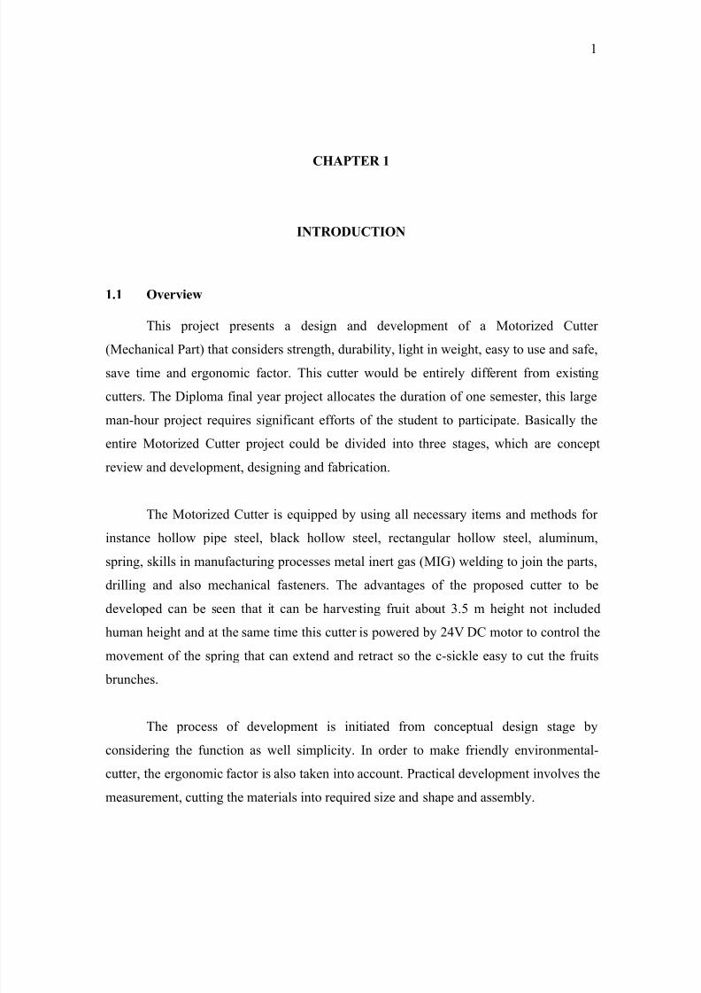
1.1 Overview
This project presents a design and development of a Motorized Cutter
(Mechanical Part) that considers strength, durability, light in weight, easy to use and safe,
save time and ergonomic factor. This cutter would be entirely different from existing
cutters. The Diploma final year project allocates the duration of one semester, this large
man-hour project requires significant efforts of the student to participate. Basically the
entire Motorized Cutter project could be divided into three stages, which are concept
review and development, designing and fabrication.
The Motorized Cutter is equipped by using all necessary items and methods for
instance hollow pipe steel, black hollow steel, rectangular hollow steel, aluminum,
spring, skills in manufacturing processes metal inert gas (MIG) welding to join the parts,
drilling and also mechanical fasteners. The advantages of the proposed cutter to be
developed can be seen that it can be harvesting fruit about 3.5 m height not included
human height and at the same time this cutter is powered by 24V DC motor to control the
movement of the spring that can extend and retract so the c-sickle easy to cut the fruits
brunches.
The process of development is initiated from conceptual design stage by
considering the function as well simplicity. In order to make friendly environmental-
cutter, the ergonomic factor is also taken into account. Practical development involves the
measurement, cutting the materials into required size and shape and assembly.
8/11/2019 Maizatul Mastura Muhammad Nazri
http://slidepdf.com/reader/full/maizatul-mastura-muhammad-nazri 14/24
2
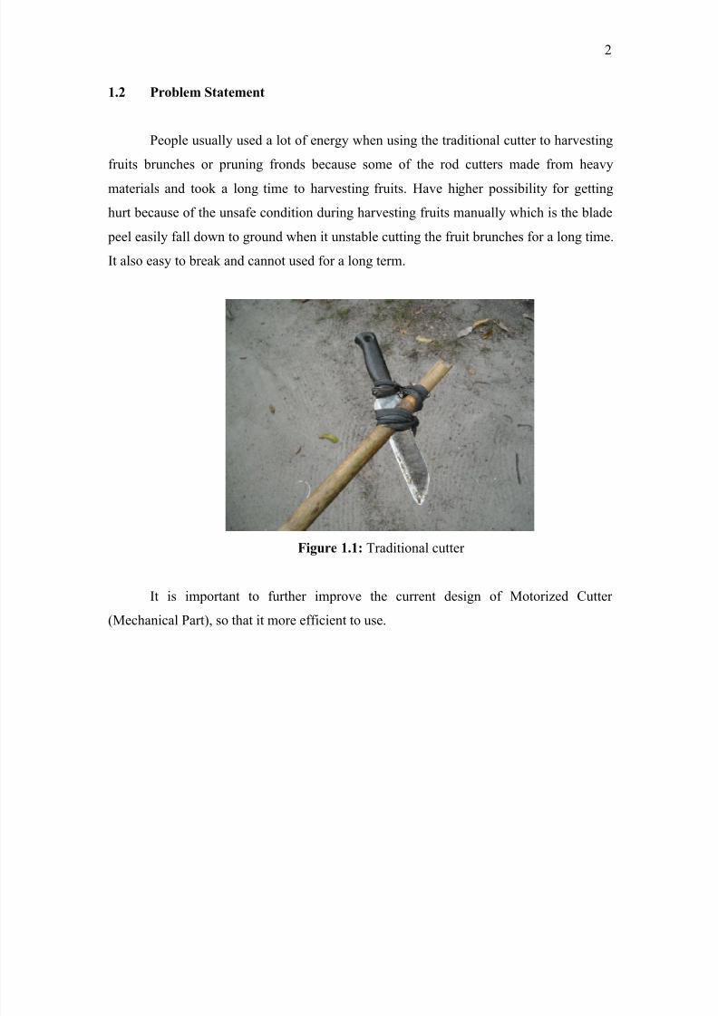
1.2 Problem Statement
People usually used a lot of energy when using the traditional cutter to harvesting
fruits brunches or pruning fronds because some of the rod cutters made from heavy
materials and took a long time to harvesting fruits. Have higher possibility for getting
hurt because of the unsafe condition during harvesting fruits manually which is the blade
peel easily fall down to ground when it unstable cutting the fruit brunches for a long time.
It also easy to break and cannot used for a long term.
Figure 1.1: Traditional cutter
It is important to further improve the current design of Motorized Cutter
(Mechanical Part), so that it more efficient to use.
8/11/2019 Maizatul Mastura Muhammad Nazri
http://slidepdf.com/reader/full/maizatul-mastura-muhammad-nazri 15/24
3
1.3 Importance of The Project
The project leads the student understand how to use the knowledge and skill
gathered before in solving problem. This project also promotes the student about
capability of research, data gathering, analysis and then solving problem scientifically.
The project also will educate the student in communication like in a presentation
and to defend their research in the presentation. The project also will generate students
that have capability to make a good research report in thesis form or technical writing.
This project also can produce and train student to capable of doing work with minimal
supervisory and more independent in searching, detailing and expanding the knowledge
and experiences.
1.4 Scope of The Project
i) Doing literature review about the cutter in the current market.
ii) Design the cutter according the sketching idea and then finalized the idea.
iii) Material considered
Hollow pipe steel Black hollow steel
Spring
Rectangular hollow steel
Aluminum
Bolt and nut
C-sickle
iv) Fabricate the cutter according the schedule.
v) Integrate the system between the mechanical part of motorized cutter and the
electro-mechanical part.
8/11/2019 Maizatul Mastura Muhammad Nazri
http://slidepdf.com/reader/full/maizatul-mastura-muhammad-nazri 16/24
4
1.5 Project Objectives
The objectives of the project are:
To design the mechanical part of a Motorized Cutter and to fabricate the
mechanical of the system.
1.6 Project Planning
The project begins with meeting the supervisor every week to define or discuss
about the project. Then, do literatures review via internet, books, supervisor, and other
relevant academic material that related to the title. The literature review is carried out
through the project to keep up with the new knowledge about the current motorized cutter
in the market.
At the same week schedule management is done using Microsoft Office. This
takes a week to accomplish. Gantt chart is shown in figure 1.1.
Then, start with the sketching idea after that choose the best idea and finalized it.The selected idea is then transfer into solid modeling and engineering using Solidwork
software.
The next task is preparation of progress presentation and report writing; both of
these tasks take two week to be done. Before the midterm presentation and submit the
report, I have prepared a speech for the presentation and double checked the report if it
has mistakes.
Using the finalized drawing and sketching as references for the measurement and
the materials needed. The fabrication process is schedule to takes on September and take
about six weeks that include integrate the system, spraying and finishing.

8/11/2019 Maizatul Mastura Muhammad Nazri
http://slidepdf.com/reader/full/maizatul-mastura-muhammad-nazri 17/24
5
Next task is the final report writing and final presentation preparation. This take
about two weeks to accomplished. The report is guided by UMP Thesis writing guided
and also the guidance from my supervisor. All the task is schedule to take about sixteen
weeks overall.
8/11/2019 Maizatul Mastura Muhammad Nazri
http://slidepdf.com/reader/full/maizatul-mastura-muhammad-nazri 18/24
6
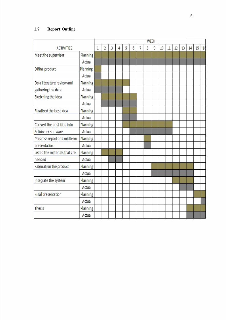
1.7 Report Outline
8/11/2019 Maizatul Mastura Muhammad Nazri
http://slidepdf.com/reader/full/maizatul-mastura-muhammad-nazri 19/24
7
CHAPTER 2
LITERATURE REVIEW
2.1 Introduction
A motorized cutter that operates at a motor speed and a control circuit that sensesthe motor speed and provides power to said motorized cutter at a level that corresponds to
the motor speed, wherein more power is provided to said motorized cutter with a
decrease in the motor speed.
The motorized cutter design is according to the present market demand and to
fulfill criteria customers needs. It should be designed to crest a product in the market so
that it will more quality and innovative.
2.2 Type of Cutter
Several Motorized Cutter with various function have been found.
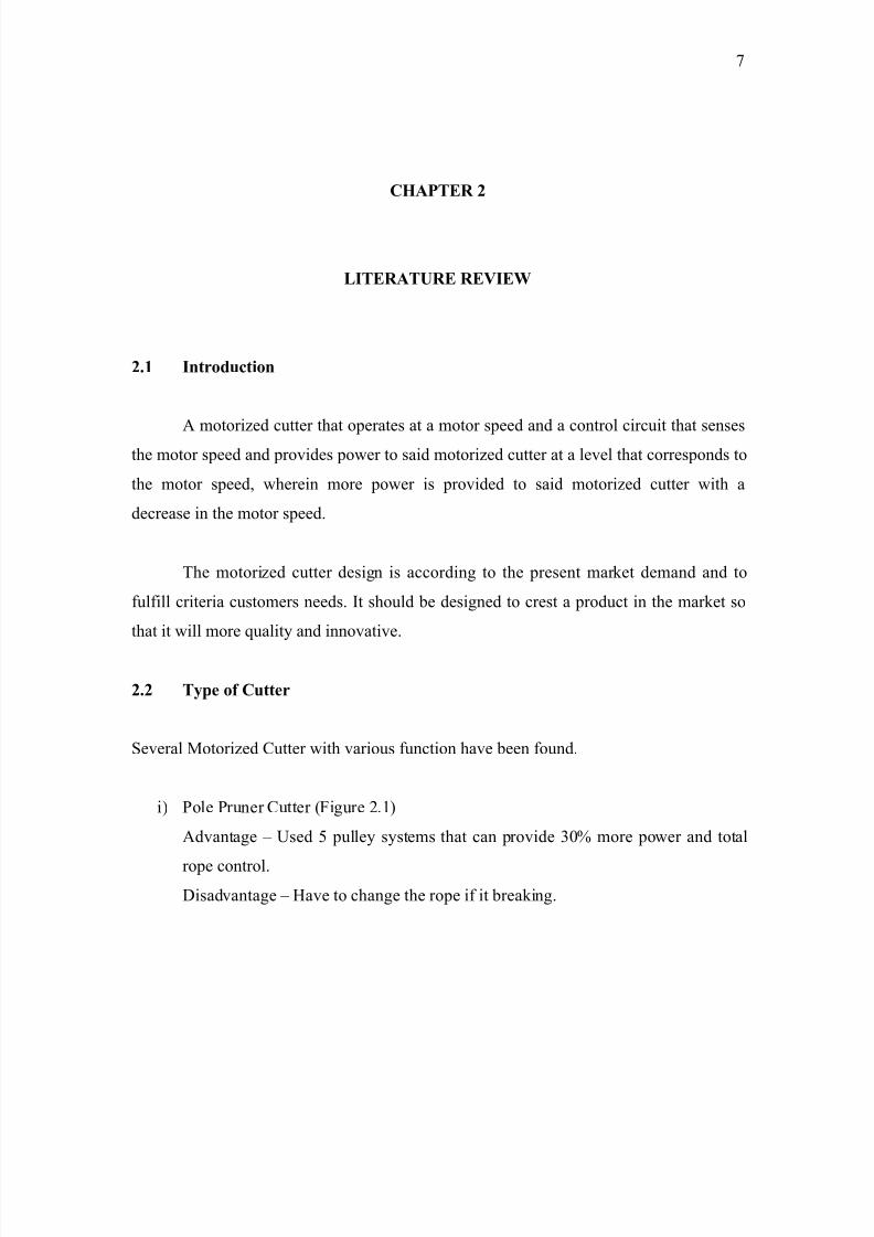
i) Pole Pruner Cutter (Figure 2.1)
Advantage – Used 5 pulley systems that can provide 30% more power and total
rope control.
Disadvantage – Have to change the rope if it breaking.
8/11/2019 Maizatul Mastura Muhammad Nazri
http://slidepdf.com/reader/full/maizatul-mastura-muhammad-nazri 20/24
8
Figure 2.1: Pole Pruner Cutter
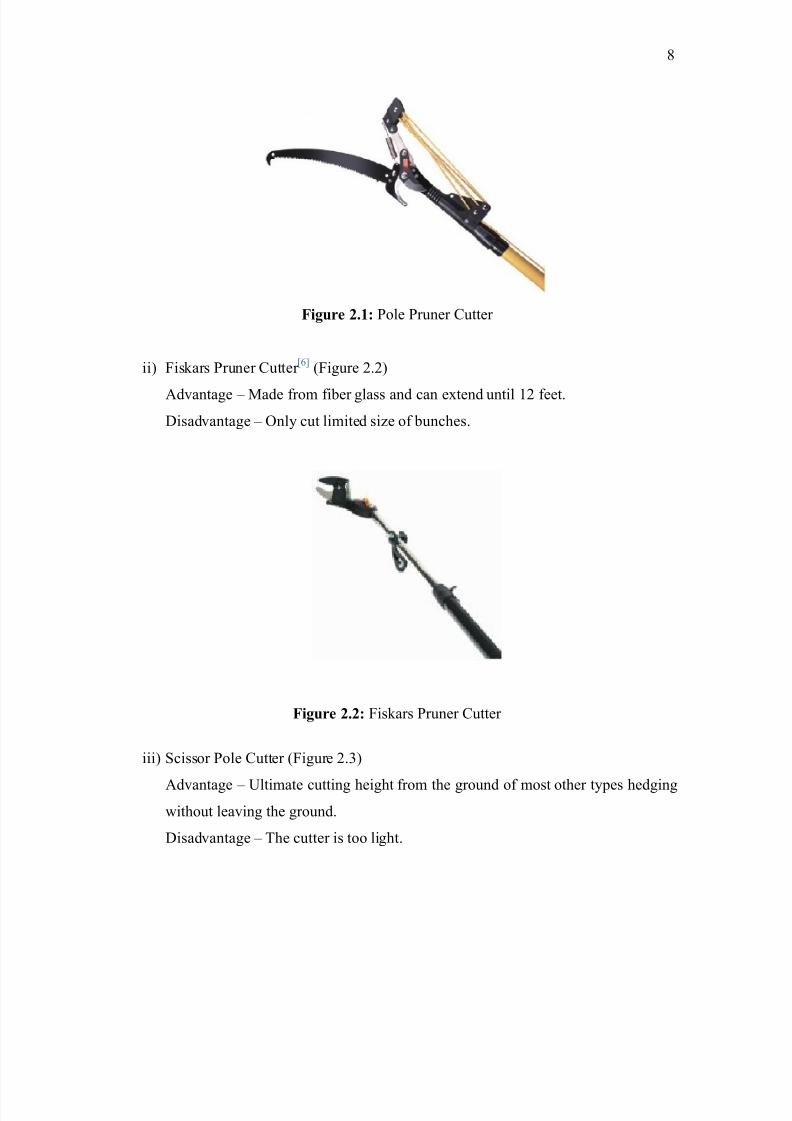
ii) Fiskars Pruner Cutter [6]
(Figure 2.2)
Advantage – Made from fiber glass and can extend until 12 feet.
Disadvantage – Only cut limited size of bunches.
Figure 2.2: Fiskars Pruner Cutter
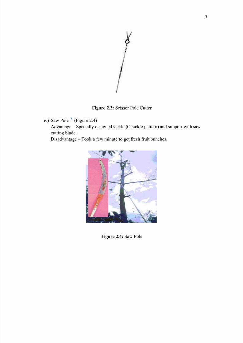
iii) Scissor Pole Cutter (Figure 2.3)
Advantage – Ultimate cutting height from the ground of most other types hedging
without leaving the ground.
Disadvantage – The cutter is too light.
8/11/2019 Maizatul Mastura Muhammad Nazri
http://slidepdf.com/reader/full/maizatul-mastura-muhammad-nazri 21/24
9
Figure 2.3: Scissor Pole Cutter
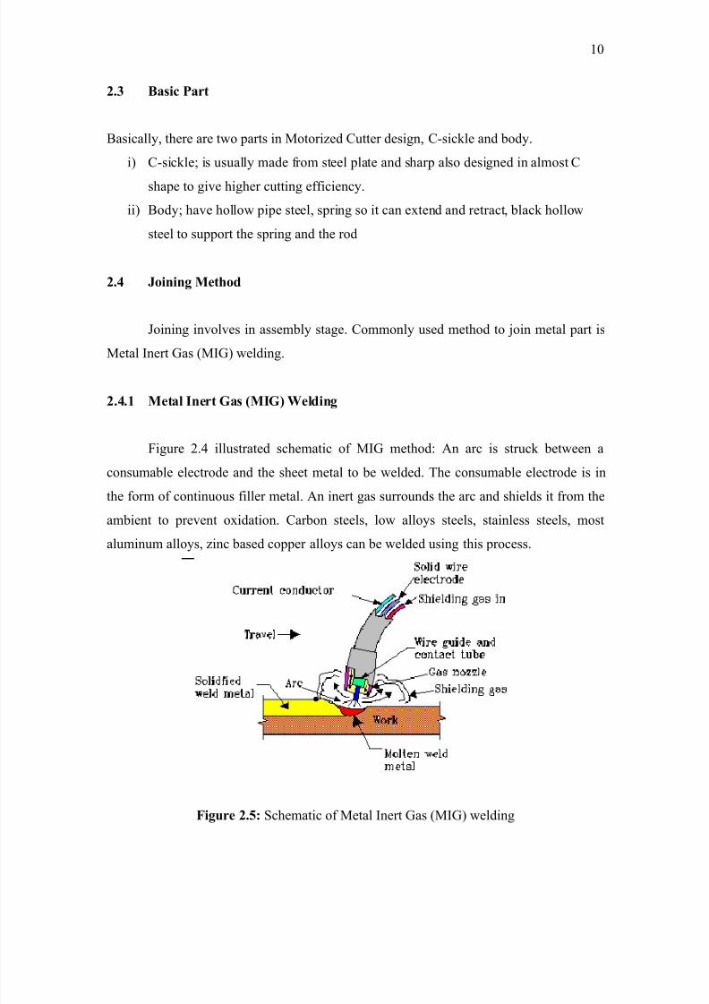
iv) Saw Pole [8] (Figure 2.4)Advantage – Specially designed sickle (C-sickle pattern) and support with saw
cutting blade.
Disadvantage – Took a few minute to get fresh fruit bunches.
Figure 2.4: Saw Pole
8/11/2019 Maizatul Mastura Muhammad Nazri
http://slidepdf.com/reader/full/maizatul-mastura-muhammad-nazri 22/24
10
2.3 Basic Part
Basically, there are two parts in Motorized Cutter design, C-sickle and body.
i) C-sickle; is usually made from steel plate and sharp also designed in almost C
shape to give higher cutting efficiency.
ii) Body; have hollow pipe steel, spring so it can extend and retract, black hollow
steel to support the spring and the rod
2.4 Joining Method
Joining involves in assembly stage. Commonly used method to join metal part is
Metal Inert Gas (MIG) welding.
2.4.1 Metal Inert Gas (MIG) Welding
Figure 2.4 illustrated schematic of MIG method: An arc is struck between a
consumable electrode and the sheet metal to be welded. The consumable electrode is in
the form of continuous filler metal. An inert gas surrounds the arc and shields it from the
ambient to prevent oxidation. Carbon steels, low alloys steels, stainless steels, most
aluminum alloys, zinc based copper alloys can be welded using this process.
Figure 2.5: Schematic of Metal Inert Gas (MIG) welding
8/11/2019 Maizatul Mastura Muhammad Nazri
http://slidepdf.com/reader/full/maizatul-mastura-muhammad-nazri 23/24
11
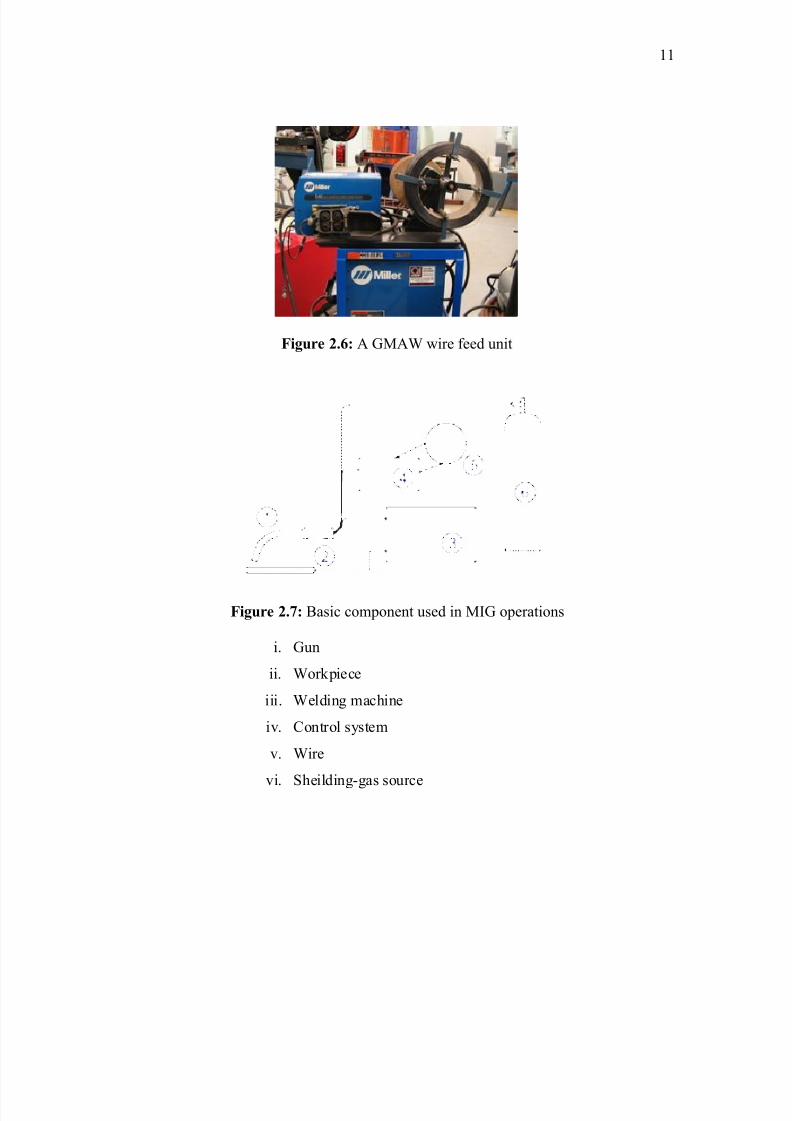
Figure 2.6: A GMAW wire feed unit
Figure 2.7: Basic component used in MIG operations
i. Gun
ii. Workpiece
iii. Welding machine
iv. Control system
v. Wire
vi. Sheilding-gas source
8/11/2019 Maizatul Mastura Muhammad Nazri
http://slidepdf.com/reader/full/maizatul-mastura-muhammad-nazri 24/24
12
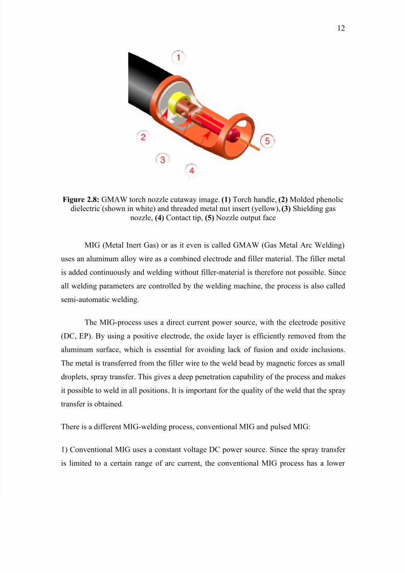
Figure 2.8: GMAW torch nozzle cutaway image. (1) Torch handle, (2) Molded phenolicdielectric (shown in white) and threaded metal nut insert (yellow), (3) Shielding gas
nozzle, (4) Contact tip, (5) Nozzle output face
MIG (Metal Inert Gas) or as it even is called GMAW (Gas Metal Arc Welding)
uses an aluminum alloy wire as a combined electrode and filler material. The filler metal
is added continuously and welding without filler-material is therefore not possible. Since
all welding parameters are controlled by the welding machine, the process is also called
semi-automatic welding.
The MIG-process uses a direct current power source, with the electrode positive
(DC, EP). By using a positive electrode, the oxide layer is efficiently removed from the
aluminum surface, which is essential for avoiding lack of fusion and oxide inclusions.
The metal is transferred from the filler wire to the weld bead by magnetic forces as small
droplets, spray transfer. This gives a deep penetration capability of the process and makes
it possible to weld in all positions. It is important for the quality of the weld that the spray
transfer is obtained.
There is a different MIG-welding process, conventional MIG and pulsed MIG:
1) Conventional MIG uses a constant voltage DC power source. Since the spray transfer
is limited to a certain range of arc current, the conventional MIG process has a lower