hb 3312391246
TRANSCRIPT
7/28/2019 Hb 3312391246
http://slidepdf.com/reader/full/hb-3312391246 1/8
Ms. Sweety patel, Prof. R.I.Patel / International Journal of Engineering Research and
Applications (IJERA) ISSN: 2248-9622 www.ijera.com
Vol. 3, Issue 3, May-Jun 2013, pp. 1239-1246
1239 | P a g e
Alternative Method of Forming Hard To Form Metal by using
LASER: A Review
Ms. Sweety patel1, Prof. R.I.Patel
2
1
M.E. (CAD/CAM) Student, Government Engineering College, Dahod Gujarat.2Professor and Head of Mechanical Engineering department Government Engineering College, Dahod Gujarat.
AbstractThis paper gives a review for a new
technique to give shape to metal by laser source
is presented. Typically metal forming by Laser is
contactless method in which laser beam is used as
energy source and by inducing temperature
induced stress in material, we can form material
in various shapes. The main benefit of laser
forming lies in its capability to form low ductility
metal and with high accuracy of forming which
normally not possible in conventional formingprocess which uses mechanical tool and die. In
this paper various experimental result and
observation of laser forming technique is
presented so that one can easily analyze the laser
forming technique and its capability and
limitations. The important parameters which
affect process results are laser beam diameter,
sheet thickness, laser input power, scan velocity
and material properties. By suitably choosing
above parameters two dimensional and three
dimensional geometry had been formed from
sheet metal.
Key words - Laser forming, temperature induced
stress, Scanning velocity.
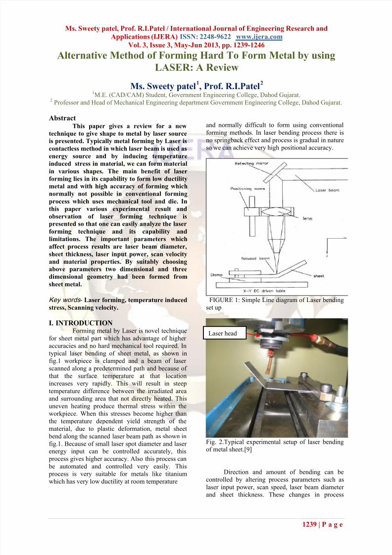
I. INTRODUCTIONForming metal by Laser is novel technique
for sheet metal part which has advantage of higher
accuracies and no hard mechanical tool required. In
typical laser bending of sheet metal, as shown in
fig.1 workpiece is clamped and a beam of laser
scanned along a predetermined path and because of
that the surface temperature at that location
increases very rapidly. This will result in steep
temperature difference between the irradiated areaand surrounding area that not directly heated. This
uneven heating produce thermal stress within the
workpiece. When this stresses become higher than
the temperature dependent yield strength of the
material, due to plastic deformation, metal sheet
bend along the scanned laser beam path as shown in
fig.1. Because of small laser spot diameter and laser energy input can be controlled accurately, this
process gives higher accuracy. Also this process can
be automated and controlled very easily. This
process is very suitable for metals like titanium
which has very low ductility at room temperature
and normally difficult to form using conventional
forming methods. In laser bending process there is
no springback effect and process is gradual in nature
so we can achieve very high positional accuracy.
FIGURE 1: Simple Line diagram of Laser bending
set up
Fig. 2.Typical experimental setup of laser bendingof metal sheet.[9]
Direction and amount of bending can be
controlled by altering process parameters such as
laser input power, scan speed, laser beam diameter and sheet thickness. These changes in process
Laser head
7/28/2019 Hb 3312391246
http://slidepdf.com/reader/full/hb-3312391246 2/8
Ms. Sweety patel, Prof. R.I.Patel / International Journal of Engineering Research and
Applications (IJERA) ISSN: 2248-9622 www.ijera.com
Vol. 3, Issue 3, May-Jun 2013, pp. 1239-1246
1240 | P a g e
parameters can be grouped to define three important
laser bending mechanisms that are discussed in
detail in following sections.
Laser Bending Mechanisms
Laser bending can be classified by mechanisms used
for achieving deformation. These mechanisms aredifferentiated from each other by parameters used;
such as, Laser beam diameter, sheet thickness, laser
input power and scan speed. These mechanisms areclassified as,
A. Temperature Gradient Mechanism
B. Buckling Mechanism
C. Upsetting Mechanism
These mechanisms are discussed in detail in
following sub-sections
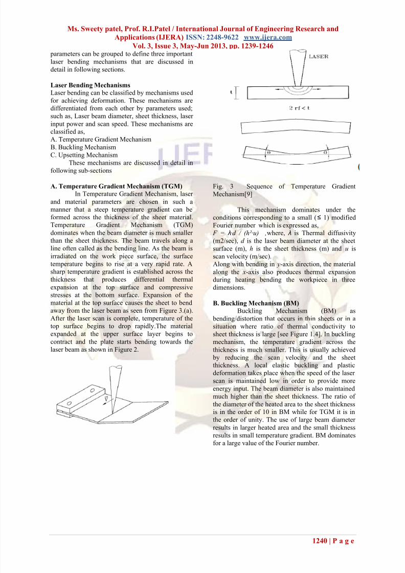
A. Temperature Gradient Mechanism (TGM)
In Temperature Gradient Mechanism, laser
and material parameters are chosen in such amanner that a steep temperature gradient can be
formed across the thickness of the sheet material.Temperature Gradient Mechanism (TGM)
dominates when the beam diameter is much smaller
than the sheet thickness. The beam travels along a
line often called as the bending line. As the beam is
irradiated on the work piece surface, the surface
temperature begins to rise at a very rapid rate. Asharp temperature gradient is established across the
thickness that produces differential thermal
expansion at the top surface and compressive
stresses at the bottom surface. Expansion of the
material at the top surface causes the sheet to bendaway from the laser beam as seen from Figure 3.(a).
After the laser scan is complete, temperature of the
top surface begins to drop rapidly.The material
expanded at the upper surface layer begins to
contract and the plate starts bending towards the
laser beam as shown in Figure 2.
Fig. 3 Sequence of Temperature Gradient
Mechanism[9]
This mechanism dominates under the
conditions corresponding to a small (≤ 1) modified
Fourier number which is expressed as,
F = λ·d / (h²·u) ,where, λ is Thermal diffusivity
(m2/sec), d is the laser beam diameter at the sheet
surface (m), h is the sheet thickness (m) and u is
scan velocity (m/sec).
Along with bending in y-axis direction, the material
along the x-axis also produces thermal expansionduring heating bending the workpiece in three
dimensions.
B. Buckling Mechanism (BM)Buckling Mechanism (BM) as
bending/distortion that occurs in thin sheets or in a
situation where ratio of thermal conductivity to
sheet thickness is large [see Figure 1.4]. In buckling
mechanism, the temperature gradient across the
thickness is much smaller. This is usually achieved
by reducing the scan velocity and the sheetthickness. A local elastic buckling and plastic
deformation takes place when the speed of the laser
scan is maintained low in order to provide more
energy input. The beam diameter is also maintained
much higher than the sheet thickness. The ratio of
the diameter of the heated area to the sheet thicknessis in the order of 10 in BM while for TGM it is in
the order of unity. The use of large beam diameter
results in larger heated area and the small thickness
results in small temperature gradient. BM dominates
for a large value of the Fourier number.
7/28/2019 Hb 3312391246
http://slidepdf.com/reader/full/hb-3312391246 3/8
Ms. Sweety patel, Prof. R.I.Patel / International Journal of Engineering Research and
Applications (IJERA) ISSN: 2248-9622 www.ijera.com
Vol. 3, Issue 3, May-Jun 2013, pp. 1239-1246
1241 | P a g e
The sheet may bend towards or away from the laser beam. direction of bending can be manipulated by
following methods;
1. Elastic prebending by external forces2. Plastic prebending
3. Relaxation of residual stresses
4. Counter bending due to temperature gradient
Bending can be achieved at a higher rate (10º / step)
using buckling mechanism, as compared to TGM
(1º- 5º / step).
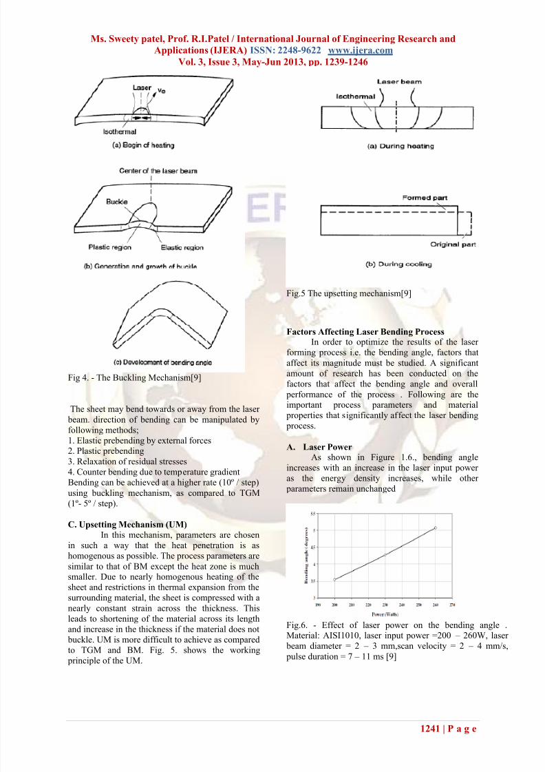
C. Upsetting Mechanism (UM)
In this mechanism, parameters are chosen
in such a way that the heat penetration is as
homogenous as possible. The process parameters are
similar to that of BM except the heat zone is muchsmaller. Due to nearly homogenous heating of the
sheet and restrictions in thermal expansion from the
surrounding material, the sheet is compressed with a
nearly constant strain across the thickness. This
leads to shortening of the material across its length
and increase in the thickness if the material does not
buckle. UM is more difficult to achieve as compared
to TGM and BM. Fig. 5. shows the working
principle of the UM.
Fig.5 The upsetting mechanism[9]
Factors Affecting Laser Bending ProcessIn order to optimize the results of the laser
forming process i.e. the bending angle, factors that
affect its magnitude must be studied. A significant
amount of research has been conducted on the
factors that affect the bending angle and overall
performance of the process . Following are the
important process parameters and material properties that significantly affect the laser bending
process.
A. Laser Power
As shown in Figure 1.6., bending angle
increases with an increase in the laser input power
as the energy density increases, while other
parameters remain unchanged
Fig.6. - Effect of laser power on the bending angle .Material: AISI1010, laser input power =200 – 260W, laser
beam diameter = 2 – 3 mm,scan velocity = 2 – 4 mm/s,
pulse duration = 7 – 11 ms [9]
Fig 4. - The Buckling Mechanism[9]
7/28/2019 Hb 3312391246
http://slidepdf.com/reader/full/hb-3312391246 4/8
Ms. Sweety patel, Prof. R.I.Patel / International Journal of Engineering Research and
Applications (IJERA) ISSN: 2248-9622 www.ijera.com
Vol. 3, Issue 3, May-Jun 2013, pp. 1239-1246
1242 | P a g e
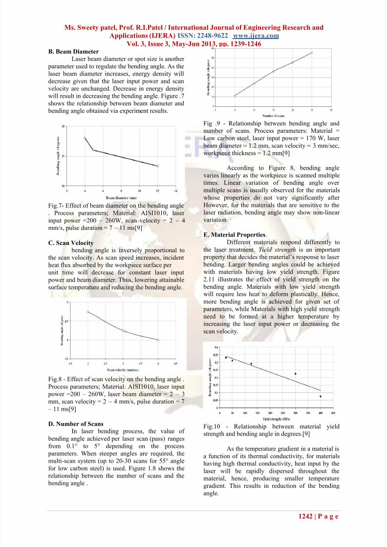
B. Beam Diameter
Laser beam diameter or spot size is another
parameter used to regulate the bending angle. As the
laser beam diameter increases, energy density will
decrease given that the laser input power and scan
velocity are unchanged. Decrease in energy density
will result in decreasing the bending angle. Figure .7shows the relationship between beam diameter and
bending angle obtained via experiment results.
Fig.7- Effect of beam diameter on the bending angle
. Process parameters; Material: AISI1010, laser
input power =200 – 260W, scan velocity = 2 – 4mm/s, pulse duration = 7 – 11 ms[9]
C. Scan Velocity
bending angle is inversely proportional to
the scan velocity. As scan speed increases, incident
heat flux absorbed by the workpiece surface per
unit time will decrease for constant laser input
power and beam diameter. Thus, lowering attainable
surface temperature and reducing the bending angle.
Fig.8 - Effect of scan velocity on the bending angle .
Process parameters; Material: AISI1010, laser input
power =200 – 260W, laser beam diameter = 2 – 3
mm, scan velocity = 2 – 4 mm/s, pulse duration = 7
– 11 ms[9]
D. Number of Scans
In laser bending process, the value of
bending angle achieved per laser scan (pass) ranges
from 0.1° to 5° depending on the process
parameters. When steeper angles are required, the
multi-scan system (up to 20-30 scans for 55° angle
for low carbon steel) is used. Figure 1.8 shows the
relationship between the number of scans and the
bending angle .
Fig .9 - Relationship between bending angle andnumber of scans. Process parameters: Material =
Low carbon steel, laser input power = 170 W, laser
beam diameter = 1.2 mm, scan velocity = 3 mm/sec,
workpiece thickness = 1.2 mm[9]
According to Figure 8, bending angle
varies linearly as the workpiece is scanned multiple
times. Linear variation of bending angle over
multiple scans is usually observed for the materialswhose properties do not vary significantly after
However, for the materials that are sensitive to thelaser radiation, bending angle may show non-linear
variation.
E. Material Properties.
Different materials respond differently to
the laser treatment. Yield strength is an important property that decides the material’s response to laser
bending. Larger bending angles could be achieved
with materials having low yield strength. Figure
2.11 illustrates the effect of yield strength on the
bending angle. Materials with low yield strengthwill require less heat to deform plastically. Hence,
more bending angle is achieved for given set of
parameters, while Materials with high yield strength
need to be formed at a higher temperature by
increasing the laser input power or decreasing the
scan velocity.
Fig.10 - Relationship between material yieldstrength and bending angle in degrees.[9]
As the temperature gradient in a material is
a function of its thermal conductivity, for materials
having high thermal conductivity, heat input by the
laser will be rapidly dispersed throughout the
material, hence, producing smaller temperaturegradient. This results in reduction of the bending
angle.
7/28/2019 Hb 3312391246
http://slidepdf.com/reader/full/hb-3312391246 5/8
Ms. Sweety patel, Prof. R.I.Patel / International Journal of Engineering Research and
Applications (IJERA) ISSN: 2248-9622 www.ijera.com
Vol. 3, Issue 3, May-Jun 2013, pp. 1239-1246
1243 | P a g e
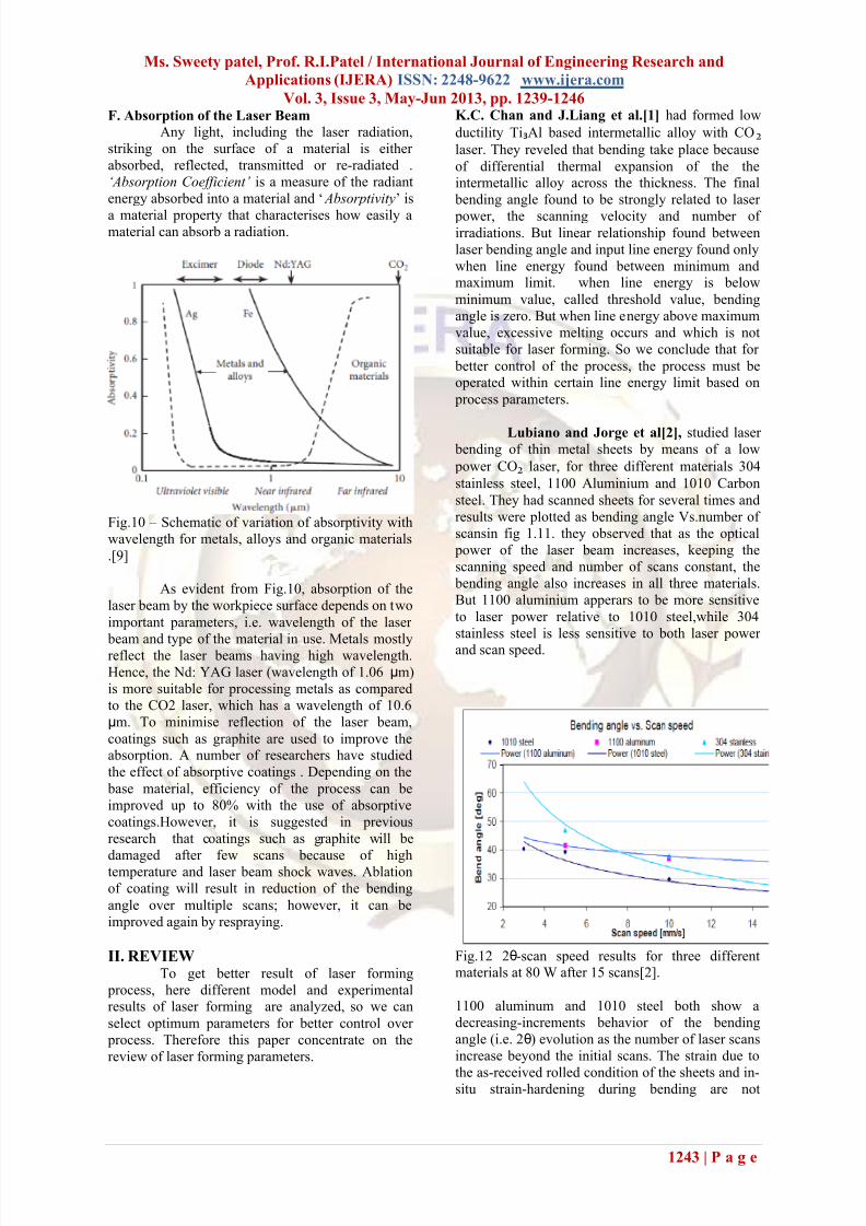
F. Absorption of the Laser Beam
Any light, including the laser radiation,
striking on the surface of a material is either
absorbed, reflected, transmitted or re-radiated .
‘Absorption Coefficient’ is a measure of the radiant
energy absorbed into a material and ‘ Absorptivity’ is
a material property that characterises how easily amaterial can absorb a radiation.
Fig.10 – Schematic of variation of absorptivity with
wavelength for metals, alloys and organic materials
.[9]
As evident from Fig.10, absorption of the
laser beam by the workpiece surface depends on two
important parameters, i.e. wavelength of the laser
beam and type of the material in use. Metals mostlyreflect the laser beams having high wavelength.
Hence, the Nd: YAG laser (wavelength of 1.06 μm)
is more suitable for processing metals as compared
to the CO2 laser, which has a wavelength of 10.6
μm. To minimise reflection of the laser beam,
coatings such as graphite are used to improve theabsorption. A number of researchers have studied
the effect of absorptive coatings . Depending on the
base material, efficiency of the process can be
improved up to 80% with the use of absorptive
coatings.However, it is suggested in previous
research that coatings such as graphite will be
damaged after few scans because of hightemperature and laser beam shock waves. Ablation
of coating will result in reduction of the bending
angle over multiple scans; however, it can be
improved again by respraying.
II. REVIEWTo get better result of laser forming
process, here different model and experimentalresults of laser forming are analyzed, so we can
select optimum parameters for better control over
process. Therefore this paper concentrate on the
review of laser forming parameters.
K.C. Chan and J.Liang et al.[1] had formed low
ductility Ti₃Al based intermetallic alloy with CO₂
laser. They reveled that bending take place because
of differential thermal expansion of the theintermetallic alloy across the thickness. The final
bending angle found to be strongly related to laser
power, the scanning velocity and number of irradiations. But linear relationship found between
laser bending angle and input line energy found only
when line energy found between minimum andmaximum limit. when line energy is below
minimum value, called threshold value, bending
angle is zero. But when line energy above maximum
value, excessive melting occurs and which is not
suitable for laser forming. So we conclude that for
better control of the process, the process must beoperated within certain line energy limit based on
process parameters.
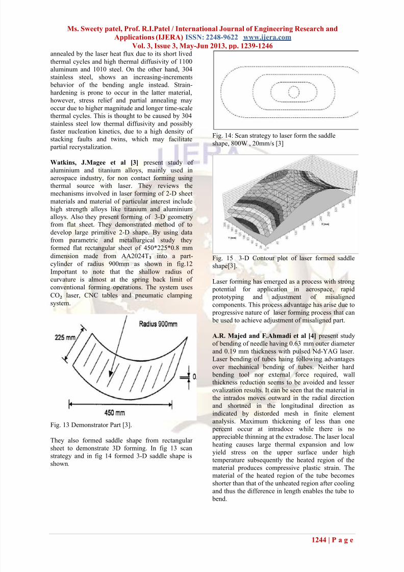
Lubiano and Jorge et al[2], studied laser bending of thin metal sheets by means of a low
power CO₂ laser, for three different materials 304
stainless steel, 1100 Aluminium and 1010 Carbon
steel. They had scanned sheets for several times and
results were plotted as bending angle Vs.number of
scansin fig 1.11. they observed that as the optical
power of the laser beam increases, keeping the
scanning speed and number of scans constant, the
bending angle also increases in all three materials.
But 1100 aluminium apperars to be more sensitive
to laser power relative to 1010 steel,while 304
stainless steel is less sensitive to both laser power
and scan speed.
Fig.12 2θ-scan speed results for three differentmaterials at 80 W after 15 scans[2].
1100 aluminum and 1010 steel both show a
decreasing-increments behavior of the bending
angle (i.e. 2θ) evolution as the number of laser scans
increase beyond the initial scans. The strain due to
the as-received rolled condition of the sheets and in-situ strain-hardening during bending are not
7/28/2019 Hb 3312391246
http://slidepdf.com/reader/full/hb-3312391246 6/8
Ms. Sweety patel, Prof. R.I.Patel / International Journal of Engineering Research and
Applications (IJERA) ISSN: 2248-9622 www.ijera.com
Vol. 3, Issue 3, May-Jun 2013, pp. 1239-1246
1244 | P a g e
annealed by the laser heat flux due to its short lived
thermal cycles and high thermal diffusivity of 1100
aluminum and 1010 steel. On the other hand, 304
stainless steel, shows an increasing-increments
behavior of the bending angle instead. Strain-
hardening is prone to occur in the latter material,
however, stress relief and partial annealing mayoccur due to higher magnitude and longer time-scale
thermal cycles. This is thought to be caused by 304
stainless steel low thermal diffusivity and possiblyfaster nucleation kinetics, due to a high density of
stacking faults and twins, which may facilitate
partial recrystalization.
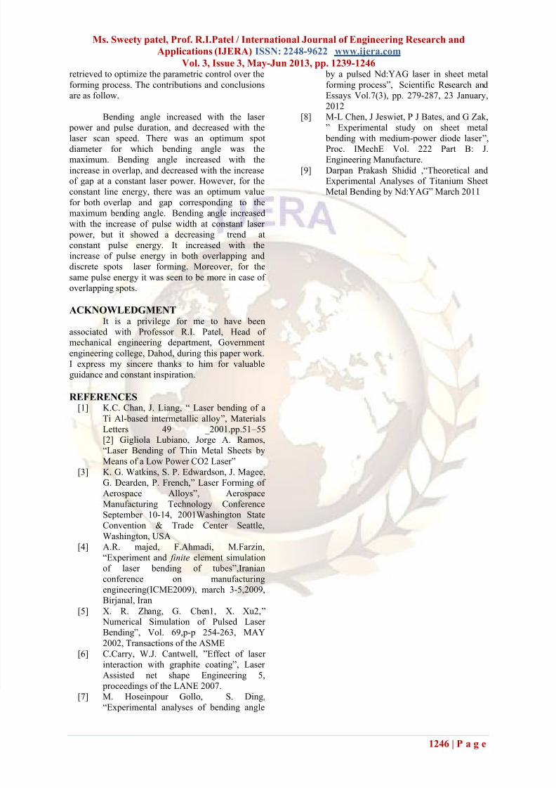
Watkins, J.Magee et al [3] present study of
aluminium and titanium alloys, mainly used in
aerospace industry, for non contact forming using
thermal source with laser. They reviews the
mechanisms involved in laser forming of 2-D sheet
materials and material of particular interest includehigh strength alloys like titanium and aluminium
alloys. Also they present forming of 3-D geometryfrom flat sheet. They demonstrated method of to
develop large primitive 2-D shape. By using data
from parametric and metallurgical study they
formed flat rectangular sheet of 450*225*0.8 mm
dimension made from AA2024T₃ into a part-
cylinder of radius 900mm as shown in fig.12
Important to note that the shallow radius of
curvature is almost at the spring back limit of
conventional forming operations. The system uses
CO₂ laser, CNC tables and pneumatic clamping
system.
Fig. 13 Demonstrator Part [3].
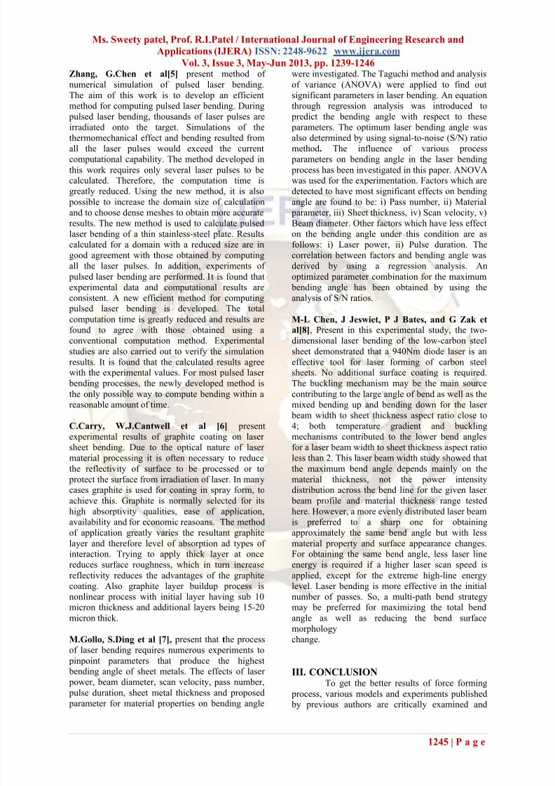
They also formed saddle shape from rectangular
sheet to demonstrate 3D forming. In fig 13 scan
strategy and in fig 14 formed 3-D saddle shape is
shown.
Fig. 14: Scan strategy to laser form the saddle
shape, 800W , 20mm/s [3]
Fig. 15 3-D Contour plot of laser formed saddle
shape[3].
Laser forming has emerged as a process with strong potential for application in aerospace, rapid
prototyping and adjustment of misaligned
components. This process advantage has arise due to
progressive nature of laser forming process that can
be used to achieve adjustment of misaligned part.
A.R. Majed and F.Ahmadi et al [4] present study
of bending of needle having 0.63 mm outer diameter
and 0.19 mm thickness with pulsed Nd-YAG laser.
Laser bending of tubes haing following advantages
over mechanical bending of tubes. Neither hard
bending tool nor external force required, wallthickness reduction seems to be avoided and lesser
ovalization results. It can be seen that the material in
the intrados moves outward in the radial directionand shortned in the longitudinal direction as
indicated by distorded mesh in finite element
analysis. Maximum thickening of less than one percent occur at intradoce while there is no
appreciable thinning at the extradose. The laser local
heating causes large thermal expansion and low
yield stress on the upper surface under high
temperature subsequently the heated region of the
material produces compressive plastic strain. The
material of the heated region of the tube becomes
shorter than that of the unheated region after cooling
and thus the difference in length enables the tube to
bend.
7/28/2019 Hb 3312391246
http://slidepdf.com/reader/full/hb-3312391246 7/8
Ms. Sweety patel, Prof. R.I.Patel / International Journal of Engineering Research and
Applications (IJERA) ISSN: 2248-9622 www.ijera.com
Vol. 3, Issue 3, May-Jun 2013, pp. 1239-1246
1245 | P a g e
Zhang, G.Chen et al[5] present method of
numerical simulation of pulsed laser bending.
The aim of this work is to develop an efficient
method for computing pulsed laser bending. During
pulsed laser bending, thousands of laser pulses are
irradiated onto the target. Simulations of the
thermomechanical effect and bending resulted fromall the laser pulses would exceed the current
computational capability. The method developed in
this work requires only several laser pulses to becalculated. Therefore, the computation time is
greatly reduced. Using the new method, it is also
possible to increase the domain size of calculation
and to choose dense meshes to obtain more accurate
results. The new method is used to calculate pulsed
laser bending of a thin stainless-steel plate. Results
calculated for a domain with a reduced size are in
good agreement with those obtained by computing
all the laser pulses. In addition, experiments of
pulsed laser bending are performed. It is found thatexperimental data and computational results are
consistent. A new efficient method for computing pulsed laser bending is developed. The total
computation time is greatly reduced and results are
found to agree with those obtained using a
conventional computation method. Experimental
studies are also carried out to verify the simulation
results. It is found that the calculated results agreewith the experimental values. For most pulsed laser
bending processes, the newly developed method is
the only possible way to compute bending within a
reasonable amount of time.
C.Carry, W.J.Cantwell et al [6] present
experimental results of graphite coating on laser
sheet bending. Due to the optical nature of laser
material processing it is often necessary to reduce
the reflectivity of surface to be processed or to
protect the surface from irradiation of laser. In manycases graphite is used for coating in spray form, to
achieve this. Graphite is normally selected for its
high absorptivity qualities, ease of application,
availability and for economic reasoans. The method
of application greatly varies the resultant graphite
layer and therefore level of absorption ad types of
interaction. Trying to apply thick layer at oncereduces surface roughness, which in turn increase
reflectivity reduces the advantages of the graphite
coating. Also graphite layer buildup process is
nonlinear process with initial layer having sub 10micron thickness and additional layers being 15-20
micron thick.
M.Gollo, S.Ding et al [7], present that the process
of laser bending requires numerous experiments to
pinpoint parameters that produce the highest bending angle of sheet metals. The effects of laser
power, beam diameter, scan velocity, pass number,
pulse duration, sheet metal thickness and proposed parameter for material properties on bending angle
were investigated. The Taguchi method and analysis
of variance (ANOVA) were applied to find out
significant parameters in laser bending. An equation
through regression analysis was introduced to
predict the bending angle with respect to these
parameters. The optimum laser bending angle was
also determined by using signal-to-noise (S/N) ratiomethod. The influence of various process
parameters on bending angle in the laser bending
process has been investigated in this paper. ANOVAwas used for the experimentation. Factors which are
detected to have most significant effects on bending
angle are found to be: i) Pass number, ii) Material
parameter, iii) Sheet thickness, iv) Scan velocity, v)
Beam diameter. Other factors which have less effect
on the bending angle under this condition are as
follows: i) Laser power, ii) Pulse duration. The
correlation between factors and bending angle was
derived by using a regression analysis. An
optimized parameter combination for the maximum bending angle has been obtained by using the
analysis of S/N ratios.
M-L Chen, J Jeswiet, P J Bates, and G Zak et
al[8], Present in this experimental study, the two-
dimensional laser bending of the low-carbon steel
sheet demonstrated that a 940Nm diode laser is an
effective tool for laser forming of carbon steelsheets. No additional surface coating is required.
The buckling mechanism may be the main source
contributing to the large angle of bend as well as the
mixed bending up and bending down for the laser
beam width to sheet thickness aspect ratio close to4; both temperature gradient and buckling
mechanisms contributed to the lower bend angles
for a laser beam width to sheet thickness aspect ratio
less than 2. This laser beam width study showed that
the maximum bend angle depends mainly on the
material thickness, not the power intensitydistribution across the bend line for the given laser
beam profile and material thickness range tested
here. However, a more evenly distributed laser beam
is preferred to a sharp one for obtaining
approximately the same bend angle but with less
material property and surface appearance changes.
For obtaining the same bend angle, less laser lineenergy is required if a higher laser scan speed is
applied, except for the extreme high-line energy
level. Laser bending is more effective in the initial
number of passes. So, a multi-path bend strategymay be preferred for maximizing the total bend
angle as well as reducing the bend surface
morphology
change.
III. CONCLUSIONTo get the better results of force forming
process, various models and experiments published by previous authors are critically examined and
7/28/2019 Hb 3312391246
http://slidepdf.com/reader/full/hb-3312391246 8/8
Ms. Sweety patel, Prof. R.I.Patel / International Journal of Engineering Research and
Applications (IJERA) ISSN: 2248-9622 www.ijera.com
Vol. 3, Issue 3, May-Jun 2013, pp. 1239-1246
1246 | P a g e
retrieved to optimize the parametric control over the
forming process. The contributions and conclusions
are as follow.
Bending angle increased with the laser
power and pulse duration, and decreased with the
laser scan speed. There was an optimum spotdiameter for which bending angle was the
maximum. Bending angle increased with the
increase in overlap, and decreased with the increaseof gap at a constant laser power. However, for the
constant line energy, there was an optimum value
for both overlap and gap corresponding to the
maximum bending angle. Bending angle increased
with the increase of pulse width at constant laser
power, but it showed a decreasing trend at
constant pulse energy. It increased with the
increase of pulse energy in both overlapping and
discrete spots laser forming. Moreover, for the
same pulse energy it was seen to be more in case of overlapping spots.
ACKNOWLEDGMENTIt is a privilege for me to have been
associated with Professor R.I. Patel, Head of mechanical engineering department, Government
engineering college, Dahod, during this paper work.
I express my sincere thanks to him for valuable
guidance and constant inspiration.
REFERENCES[1] K.C. Chan, J. Liang, “ Laser bending of a
Ti Al-based intermetallic alloy”, Materials
Letters 49 _2001.pp.51 – 55[2] Gigliola Lubiano, Jorge A. Ramos,
“Laser Bending of Thin Metal Sheets by
Means of a Low Power CO2 Laser”
[3] K. G. Watkins, S. P. Edwardson, J. Magee,
G. Dearden, P. French,” Laser Forming of
Aerospace Alloys”, Aerospace
Manufacturing Technology Conference
September 10-14, 2001Washington State
Convention & Trade Center Seattle,
Washington, USA
[4] A.R. majed, F.Ahmadi, M.Farzin,
“Experiment and finite element simulation
of laser bending of tubes”,Iranian
conference on manufacturing
engineering(ICME2009), march 3-5,2009,
Birjanal, Iran
[5] X. R. Zhang, G. Chen1, X. Xu2,” Numerical Simulation of Pulsed Laser
Bending”, Vol. 69,p-p 254-263, MAY
2002, Transactions of the ASME
[6] C.Carry, W.J. Cantwell, ”Effect of laser
interaction with graphite coating”, Laser
Assisted net shape Engineering 5,
proceedings of the LANE 2007.
[7] M. Hoseinpour Gollo, S. Ding,
“Experimental analyses of bending angle
by a pulsed Nd:YAG laser in sheet metal
forming process”, Scientific Research and
Essays Vol.7(3), pp. 279-287, 23 January,
2012
[8] M-L Chen, J Jeswiet, P J Bates, and G Zak,
” Experimental study on sheet metal
bending with medium-power diode laser ”, Proc. IMechE Vol. 222 Part B: J.
Engineering Manufacture.
[9] Darpan Prakash Shidid ,“Theoretical andExperimental Analyses of Titanium Sheet
Metal Bending by Nd:YAG” March 2011