gpc catalogue 07082017 lo -...
TRANSCRIPT
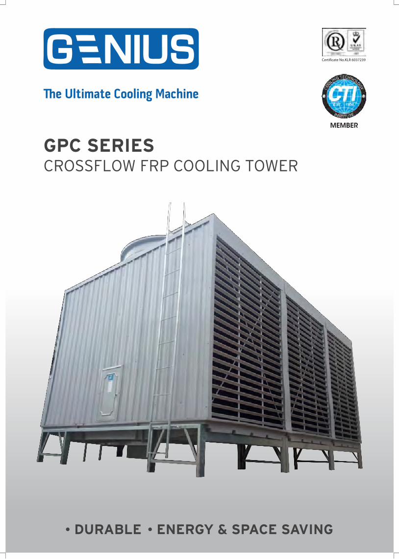
GPC SERIESCROSSFLOW FRP COOLING TOWER
DURABLE ENERGY & SPACE SAVING

1
MYDIN SENAWANG
HOTEL ISTANABANK NEGARA TERENGGANU
ECONSAVE (VARIOUS OUTLETS) KUALA TERENGGANU SPECIALIST HOSPITAL
KOSSAN RUBBER INDUSTRIES BHD IMPERIAL HOTEL AND PERMAISURIIMPERIAL CITY MALL MIRI
2
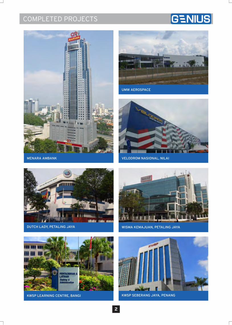
MENARA AMBANK
UMW AEROSPACE
VELODROM NASIONAL, NILAI
DUTCH LADY, PETALING JAYA
KWSP SEBERANG JAYA, PENANGKWSP LEARNING CENTRE, BANGI
WISMA KEMAJUAN, PETALING JAYA
3
TOWER SPECIFICATION GPC SERIES
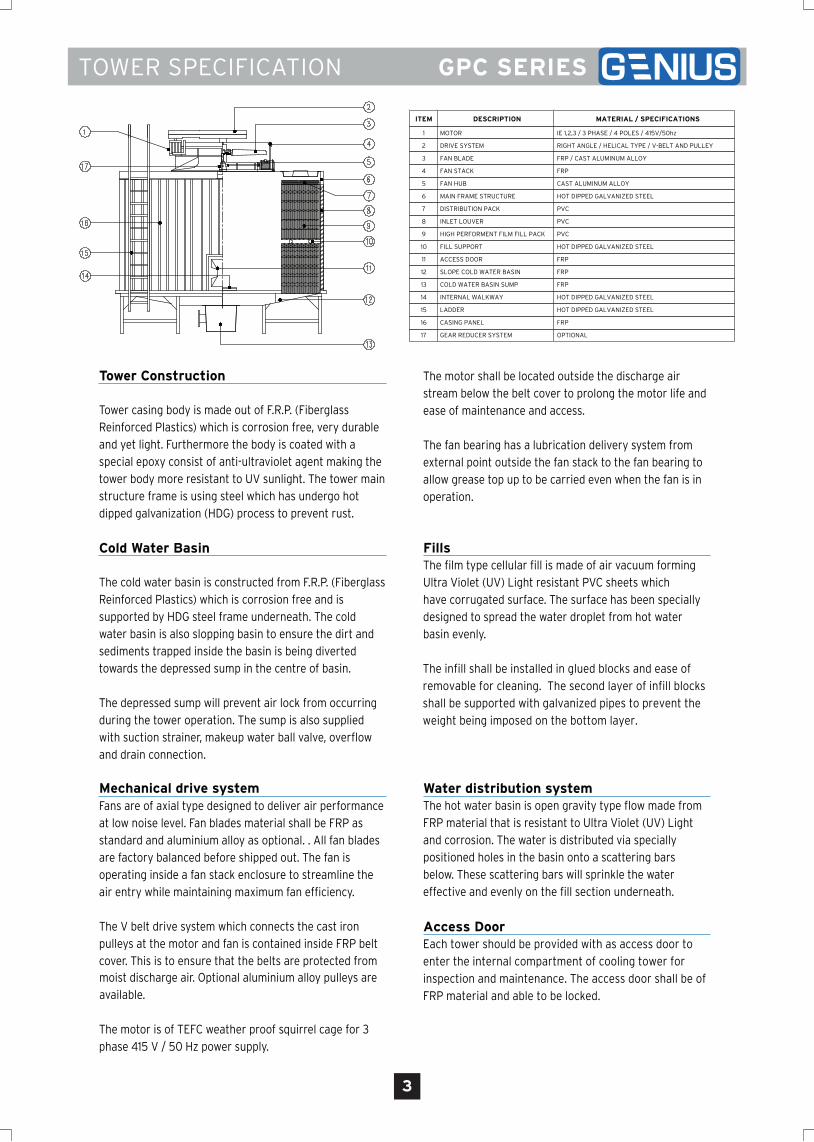
ITEM DESCRIPTION MATERIAL / SPECIFICATIONS
1 MOTOR IE 1,2,3 / 3 PHASE / 4 POLES / 415V/50hz
2 DRIVE SYSTEM RIGHT ANGLE / HELICAL TYPE / V-BELT AND PULLEY
3 FAN BLADE FRP / CAST ALUMINUM ALLOY
4 FAN STACK FRP
5 FAN HUB CAST ALUMINUM ALLOY
6 MAIN FRAME STRUCTURE HOT DIPPED GALVANIZED STEEL
7 DISTRIBUTION PACK PVC
8 INLET LOUVER PVC
9 HIGH PERFORMENT FILM FILL PACK PVC
10 FILL SUPPORT HOT DIPPED GALVANIZED STEEL
11 ACCESS DOOR FRP
12 SLOPE COLD WATER BASIN FRP
13 COLD WATER BASIN SUMP FRP
14 INTERNAL WALKWAY HOT DIPPED GALVANIZED STEEL
15 LADDER HOT DIPPED GALVANIZED STEEL
16 CASING PANEL FRP
17 GEAR REDUCER SYSTEM OPTIONAL
Tower Construction
Tower casing body is made out of F.R.P. (FiberglassReinforced Plastics) which is corrosion free, very durableand yet light. Furthermore the body is coated with aspecial epoxy consist of anti-ultraviolet agent making thetower body more resistant to UV sunlight. The tower mainstructure frame is using steel which has undergo hotdipped galvanization (HDG) process to prevent rust.
FillsThe film type cellular fill is made of air vacuum formingUltra Violet (UV) Light resistant PVC sheets whichhave corrugated surface. The surface has been speciallydesigned to spread the water droplet from hot waterbasin evenly.
Water distribution systemThe hot water basin is open gravity type flow made fromFRP material that is resistant to Ultra Violet (UV) Lightand corrosion. The water is distributed via speciallypositioned holes in the basin onto a scattering barsbelow. These scattering bars will sprinkle the watereffective and evenly on the fill section underneath.
The motor is of TEFC weather proof squirrel cage for 3phase 415 V / 50 Hz power supply.
The motor shall be located outside the discharge airstream below the belt cover to prolong the motor life andease of maintenance and access.
The fan bearing has a lubrication delivery system fromexternal point outside the fan stack to the fan bearing toallow grease top up to be carried even when the fan is inoperation.
Cold Water Basin
The cold water basin is constructed from F.R.P. (FiberglassReinforced Plastics) which is corrosion free and issupported by HDG steel frame underneath. The coldwater basin is also slopping basin to ensure the dirt andsediments trapped inside the basin is being divertedtowards the depressed sump in the centre of basin.
The depressed sump will prevent air lock from occurringduring the tower operation. The sump is also suppliedwith suction strainer, makeup water ball valve, overflowand drain connection.
moist discharge air. Optional aluminium alloy pulleys areavailable.
Mechanical drive systemFans are of axial type designed to deliver air performanceat low noise level. Fan blades material shall be FRP asstandard and aluminium alloy as optional. . All fan bladesare factory balanced before shipped out. The fan isoperating inside a fan stack enclosure to streamline theair entry while maintaining maximum fan efficiency.
The V belt drive system which connects the cast ironpulleys at the motor and fan is contained inside FRP beltcover. This is to ensure that the belts are protected from
The infill shall be installed in glued blocks and ease of
removable for cleaning. The second layer of infill blocks
shall be supported with galvanized pipes to prevent the
weight being imposed on the bottom layer.
Access DoorEach tower should be provided with as access door to
enter the internal compartment of cooling tower for
inspection and maintenance. The access door shall be of
FRP material and able to be locked.

4
TECHNICAL DATA FOR GPC SERIES
NO
TE
:
1. T
he
bas
ic d
esig
n c
on
dit
ion
of
GP
C s
erie
s is
bas
ed o
n h
ot
wat
er in
let
37
°C, c
old
wat
er o
utl
et :
32
°C, A
mb
ien
t W
B: 2
7°C
, 13
ℓ/m
in/H
RT
wat
er f
low
rat
e.2
. Man
ufa
ctu
rer
rese
rve
the
rig
ht
to c
han
ge
the
tech
nic
al d
ata
for
imp
rove
men
t o
f p
rod
uct
s w
ith
ou
t p
rio
r n
oti
ce.
3. T
he
pu
mp
hea
d r
equ
ires
is a
pp
oro
xim
atel
y th
e h
eig
ht
of
the
coo
ling
to
wer
.
TE
CH
NIC
AL
DA
TA
- L
OW
NO
ISE
GP
C
100
GP
C
125
GP
C
150
GP
C
175
GP
C
20
0
GP
C
22
5
GP
C
25
0
GP
C
30
0
GP
C
35
0
GP
C
40
0
GP
C
45
0
GP
C
50
0
GP
C
60
0
GP
C
70
0
GP
C
75
0
GP
C
80
0
GP
C
90
0
GP
C
100
0
Coo
ling
Ca
paci
tyH
RT
100
125
150
175
20
02
25
25
03
00
35
04
00
45
05
00
60
07
00
75
08
00
90
010
00
He
at
Re
ject
ions
kca
l/h
39
0,0
00
48
7,5
00
58
5,0
00
68
2,5
00
78
0,0
00
87
7,5
00
97
5,0
00
1,17
0,0
00
1,36
5,0
00
1,56
0,0
00
1,75
0,0
00
1,95
0,0
00
2,3
40
,00
02
,72
5,5
75
2,9
25
,00
03
,120
,00
03
,510
,00
03
,90
0,0
00
Wa
ter
Flo
w R
ate
m3/h
r7
89
811
713
715
617
519
52
34
27
43
123
50
39
04
68
54
55
85
62
47
00
78
0
Hot
Wa
ter
Te
mp.
ºC
Col
d W
ate
r T
em
p.ºC
We
t B
ulb
Te
mp.
ºC
Wid
th (
W)
mm
33
00
33
00
37
00
37
00
40
00
44
00
44
00
37
00
37
00
40
00
44
00
44
00
40
00
44
00
44
00
40
00
44
00
44
00
Le
ngth
(L
)m
m19
1019
1019
1019
102
110
25
05
25
05
38
20
38
20
42
20
50
105
010
63
30
75
157
515
84
40
100
20
100
20
Tot
al H
eig
htm
m3
72
03
72
03
72
03
72
03
76
53
72
03
72
03
72
03
72
03
76
53
72
03
72
03
76
53
72
03
72
03
76
53
72
03
72
0
Typ
e
Dia
me
ter
x Q
tym
m15
00
x 1
150
0 x
115
00
x 1
150
0 x
117
00
x 1
20
00
x 1
20
00
x 1
150
0 x
215
00
x 2
170
0 x
22
00
0 x
22
00
0 x
217
00
x 3
20
00
x 3
20
00
x 3
170
0 x
42
00
0 x
42
00
0 x
4
Num
ber
of B
lade
s
Fa
n S
pee
drp
m4
90
49
04
90
57
55
103
80
42
54
90
57
55
103
80
42
55
103
80
42
55
103
80
510
Dri
ve S
yste
m
Typ
e
Pow
er
Sou
rce
Ra
ted
Out
put
x Q
tykw
2.2
x 1
3.7
x 1
3.7
x 1
5.5
x 1
5.5
x 1
5.5
x 1
7.5
x 1
3.7
x 2
5.5
x 2
5.5
x 2
5.5
x 2
7.5
x 2
5.5
x 3
5.5
x 3
7.5
x 3
5.5
x 4
5.5
x 4
7.5
x 4
Inle
t P
ipe
mm
100
x 2
100
x 2
100
x 2
100
x 2
125
x 2
125
x 2
125
x 2
100
x 4
100
x 4
125
x 4
125
x 4
125
x 4
125
x 6
125
x 6
125
x 6
125
x 8
125
x 8
125
x 8
Out
let
Pip
em
m12
5 x
112
5 x
112
5 x
115
0 x
115
0 x
12
00
x 1
20
0 x
12
00
x 1
20
0 x
12
50
x 1
25
0 x
12
50
x 1
20
0 x
22
00
x 2
20
0 x
22
50
x 2
25
0 x
22
50
x 2
Dra
in p
ipe
mm
50
x 1
50
x 1
50
x 1
50
x 1
50
x 1
50
x 1
50
x 1
50
x 1
50
x 1
50
x 1
50
x 1
50
x 1
50
x 2
50
x 2
50
x 2
50
x 2
50
x 2
50
x 2
Ove
rflo
w p
ipe
mm
50
x 1
50
x 1
50
x 1
50
x 1
50
x 1
50
x 1
50
x 1
50
x 1
50
x 1
50
x 1
50
x 1
50
x 1
50
x 2
50
x 2
50
x 2
50
x 2
50
x 2
50
x 2
Aut
o m
ake
up
mm
25
x 1
25
x 1
25
x 1
25
x 1
25
x 1
25
x 1
25
x 1
40
x 1
40
x 1
50
x 1
50
x 1
50
x 1
40
x 2
40
x 2
40
x 2
50
x 2
50
x 2
50
x 2
Ma
nua
l ma
ke u
pm
m2
5 x
12
5 x
12
5 x
12
5 x
12
5 x
12
5 x
12
5 x
14
0 x
14
0 x
15
0 x
15
0 x
15
0 x
14
0 x
24
0 x
24
0 x
25
0 x
25
0 x
25
0 x
2
Eva
pora
tion
loss
%
Dri
ft lo
ss%
Dry
we
ight
kg9
85
99
512
50
127
013
00
150
015
50
24
00
24
30
25
102
90
02
94
03
80
04
32
04
33
05
20
06
00
06
20
0
Ope
rati
ng w
eig
htkg
215
02
160
26
30
26
80
28
50
37
20
37
70
510
05
140
56
00
69
00
72
00
85
00
109
00
110
00
114
00
145
00
148
00
Mo
del
1 C
ell
2 C
ell
s
Ca
paci
ty
Fa
n C
ylin
der
Fa
n
Axi
al F
low
4
Ove
rall
Dim
ens
ion
Ma
teri
al
Ca
sing
Fra
me
wor
k
Fill
Wa
ter
Sum
p
Dis
trib
utio
n B
asi
n
Col
d W
ate
r B
asi
n
Fa
n A
sse
mbl
y
We
ight
D
istr
ibut
ion
Sys
tem
Pip
ing
Dim
ens
ion
Ma
ke-u
p
Mot
or
3 C
ell
s4
Cell
s
FR
P
Hot
-Dip
Ga
lva
nniz
ed
Ste
el
PV
C
37
32
27
0.9
2
0.0
2
V-B
elt
and
Pul
ley
TE
FC
/ 4
pol
es
415
V/3
Ph/
50
Hz
Ope
n G
ravi
ty T
ype
Flo
w
FR
P
FR
P
FR
P
Hub
: Ca
st A
lum
iniu
m A
lloy,
Bla
de: F
RP
FR
P
5
TECHNICAL DATA FOR GPC SERIES
NO
TE
:
1. T
he
bas
ic d
esig
n c
on
dit
ion
of
GP
C s
erie
s is
bas
ed o
n h
ot
wat
er in
let
37
°C, c
old
wat
er o
utl
et :
32
°C, A
mb
ien
t W
B: 2
7°C
, 13
ℓ/m
in/H
RT
wat
er f
low
rat
e.2
. Man
ufa
ctu
rer
rese
rve
the
rig
ht
to c
han
ge
the
tech
nic
al d
ata
for
imp
rove
men
t o
f p
rod
uct
s w
ith
ou
t p
rio
r n
oti
ce.
3. T
he
pu
mp
hea
d r
equ
ires
is a
pp
oro
xim
atel
y th
e h
eig
ht
of
the
coo
ling
to
wer
.
TE
CH
NIC
AL
DA
TA
- C
OM
PA
CT
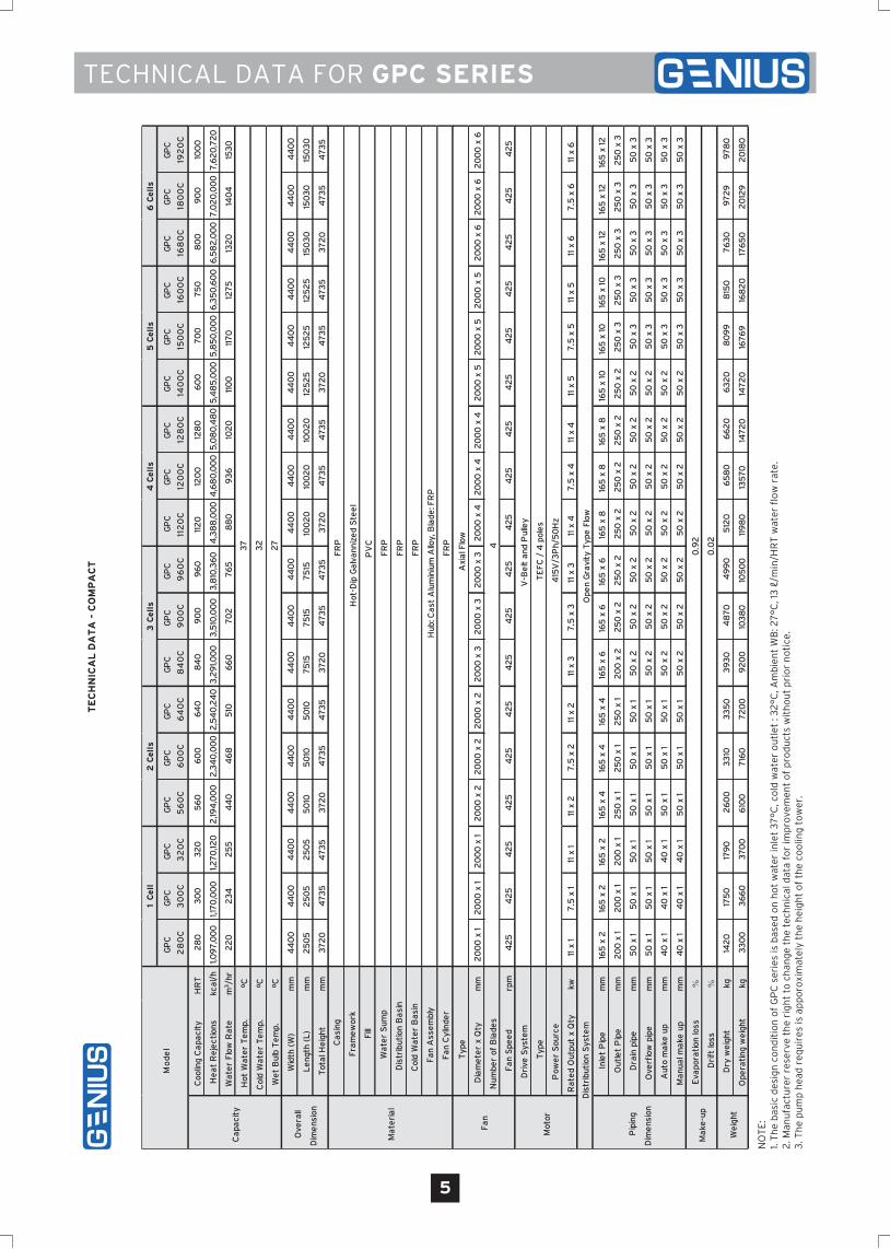
GP
C
28
0C
GP
C
30
0C
GP
C
32
0C
GP
C
56
0C
GP
C
60
0C
GP
C
64
0C
GP
C
84
0C
GP
C
90
0C
GP
C
96
0C
GP
C
112
0C
GP
C
120
0C
GP
C
128
0C
GP
C
140
0C
GP
C
150
0C
GP
C
160
0C
GP
C
168
0C
GP
C
180
0C
GP
C
192
0C
Coo
ling
Ca
paci
tyH
RT
28
03
00
32
05
60
60
06
40
84
09
00
96
011
20
120
012
80
60
07
00
75
08
00
90
010
00
He
at
Re
ject
ions
kca
l/h
1,09
7,0
00
1,17
0,0
00
1,27
0,12
02
,194
,00
02
,34
0,0
00
2,5
40
,24
03
,29
1,00
03
,510
,00
03
,810
,36
04
,38
8,0
00
4,6
80
,00
05
,08
0,4
80
5,4
85
,00
05
,85
0,0
00
6,3
50
,60
06
,58
2,0
00
7,0
20
,00
07
,62
0,7
20
Wa
ter
Flo
w R
ate
m3/h
r2
20
23
42
55
44
04
68
510
66
07
02
76
58
80
93
610
20
110
011
70
127
513
20
140
415
30
Hot
Wa
ter
Te
mp.
ºC
Col
d W
ate
r T
em
p.ºC
We
t B
ulb
Te
mp.
ºC
Wid
th (
W)
mm
44
00
44
00
44
00
44
00
44
00
44
00
44
00
44
00
44
00
44
00
44
00
44
00
44
00
44
00
44
00
44
00
44
00
44
00
Le
ngth
(L
)m
m2
50
52
50
52
50
55
010
50
105
010
75
157
515
75
1510
02
010
02
010
02
012
52
512
52
512
52
515
03
015
03
015
03
0
Tot
al H
eig
htm
m3
72
04
73
54
73
53
72
04
73
54
73
53
72
04
73
54
73
53
72
04
73
54
73
53
72
04
73
54
73
53
72
04
73
54
73
5
Typ
e
Dia
me
ter
x Q
tym
m2
00
0 x
12
00
0 x
12
00
0 x
12
00
0 x
22
00
0 x
22
00
0 x
22
00
0 x
32
00
0 x
32
00
0 x
32
00
0 x
42
00
0 x
42
00
0 x
42
00
0 x
52
00
0 x
52
00
0 x
52
00
0 x
62
00
0 x
62
00
0 x
6
Num
ber
of B
lade
s
Fa
n S
pee
drp
m4
25
42
54
25
42
54
25
42
54
25
42
54
25
42
54
25
42
54
25
42
54
25
42
54
25
42
5
Dri
ve S
yste
m
Typ
e
Pow
er
Sou
rce
Ra
ted
Out
put
x Q
tykw
11 x
17
.5 x
111
x 1
11 x
27
.5 x
211
x 2
11 x
37
.5 x
311
x 3
11 x
47
.5 x
411
x 4
11 x
57
.5 x
511
x 5
11 x
67
.5 x
611
x 6
Inle
t P
ipe
mm
165
x 2
165
x 2
165
x 2
165
x 4
165
x 4
165
x 4
165
x 6
165
x 6
165
x 6
165
x 8
165
x 8
165
x 8
165
x 1
016
5 x
10
165
x 1
016
5 x
12
165
x 1
216
5 x
12
Out
let
Pip
em
m2
00
x 1
20
0 x
12
00
x 1
25
0 x
12
50
x 1
25
0 x
12
00
x 2
25
0 x
22
50
x 2
25
0 x
22
50
x 2
25
0 x
22
50
x 2
25
0 x
32
50
x 3
25
0 x
32
50
x 3
25
0 x
3
Dra
in p
ipe
mm
50
x 1
50
x 1
50
x 1
50
x 1
50
x 1
50
x 1
50
x 2
50
x 2
50
x 2
50
x 2
50
x 2
50
x 2
50
x 2
50
x 3
50
x 3
50
x 3
50
x 3
50
x 3
Ove
rflo
w p
ipe
mm
50
x 1
50
x 1
50
x 1
50
x 1
50
x 1
50
x 1
50
x 2
50
x 2
50
x 2
50
x 2
50
x 2
50
x 2
50
x 2
50
x 3
50
x 3
50
x 3
50
x 3
50
x 3
Aut
o m
ake
up
mm
40
x 1
40
x 1
40
x 1
50
x 1
50
x 1
50
x 1
50
x 2
50
x 2
50
x 2
50
x 2
50
x 2
50
x 2
50
x 2
50
x 3
50
x 3
50
x 3
50
x 3
50
x 3
Ma
nua
l ma
ke u
pm
m4
0 x
14
0 x
14
0 x
15
0 x
15
0 x
15
0 x
15
0 x
25
0 x
25
0 x
25
0 x
25
0 x
25
0 x
25
0 x
25
0 x
35
0 x
35
0 x
35
0 x
35
0 x
3
Eva
pora
tion
loss
%
Dri
ft lo
ss%
Dry
we
ight
kg14
20
175
017
90
26
00
33
103
35
03
93
04
87
04
99
05
120
65
80
66
20
63
20
80
99
815
07
63
09
72
99
78
0
Ope
rati
ng w
eig
htkg
33
00
36
60
37
00
610
07
160
72
00
92
00
103
80
105
00
119
80
135
70
147
20
147
20
167
69
168
20
176
50
20
129
20
180
Mo
del
5 C
ell
s6
Cell
s
Dis
trib
utio
n B
asi
nF
RP
Ca
paci
ty3
7
32
27
Ove
rall
Dim
ens
ion
Ma
teri
al
Ca
sing
FR
P
Fra
me
wor
kH
ot-D
ip G
alv
ann
ize
d S
tee
l
Pip
ing
Dim
ens
ion
Ma
ke-u
p0
.92
0.0
2
Fa
n
Axi
al F
low
4
Mot
or
V-B
elt
and
Pul
ley
TE
FC
/ 4
pol
es
415
V/3
Ph/
50
Hz
1 C
ell
2 C
ell
s3
Cell
s4
Cell
s
D
istr
ibut
ion
Sys
tem
Ope
n G
ravi
ty T
ype
Flo
w
Col
d W
ate
r B
asi
nF
RP
Fa
n A
sse
mbl
yH
ub: C
ast
Alu
min
ium
Allo
y, B
lade
: FR
P
Fa
n C
ylin
der
FR
P
Fill
P
VC
Wa
ter
Sum
pF
RP
We
ight

6
TECHNICAL DATA FOR GPC SERIES
NO
TE
:
1. T
he
bas
ic d
esig
n c
on
dit
ion
of
GP
C s
erie
s is
bas
ed o
n h
ot
wat
er in
let
37
°C, c
old
wat
er o
utl
et :
32
°C, A
mb
ien
t W
B: 2
7°C
, 13
ℓ/m
in/H
RT
wat
er f
low
rat
e.2
. Man
ufa
ctu
rer
rese
rve
the
rig
ht
to c
han
ge
the
tech
nic
al d
ata
for
imp
rove
men
t o
f p
rod
uct
s w
ith
ou
t p
rio
r n
oti
ce.
3. T
he
pu
mp
hea
d r
equ
ires
is a
pp
oro
xim
atel
y th
e h
eig
ht
of
the
coo
ling
to
wer
.
TE
CH
NIC
AL
DA
TA
- S
UP
ER
LO
W N
OIS
E
GP
C
100
S
GP
C
125
S
GP
C
150
S
GP
C
175
S
GP
C
20
0S
GP
C
22
5S
GP
C
25
0S
GP
C
30
0S
GP
C
35
0S
GP
C
40
0S
GP
C
45
0S
GP
C
50
0S
GP
C
60
0S
GP
C
70
0S
GP
C
75
0S
GP
C
80
0S
GP
C
90
0S
GP
C
100
0S
Coo
ling
Ca
paci
tyH
RT
100
125
150
175
20
02
25
25
03
00
35
04
00
45
05
00
60
07
00
75
08
00
90
010
00
He
at
Re
ject
ions
kca
l/h
39
0,0
00
48
7,5
00
58
5,0
00
68
2,5
00
78
0,0
00
87
7,5
00
97
5,0
00
1,17
0,0
00
1,36
5,0
00
1,56
0,0
00
1,75
0,0
00
1,95
0,0
00
2,3
40
,00
02
,72
5,5
75
2,9
25
,00
03
,120
,00
03
,510
,00
03
,90
0,0
00
Wa
ter
Flo
w R
ate
m3/h
r7
89
811
713
715
617
519
52
34
27
43
123
50
39
04
68
54
55
85
62
47
00
78
0
Hot
Wa
ter
Te
mp.
ºC
Col
d W
ate
r T
em
p.ºC
We
t B
ulb
Te
mp.
ºC
Wid
th (
W)
mm
33
00
33
00
37
00
37
00
40
00
44
00
44
00
37
00
37
00
40
00
44
00
44
00
40
00
44
00
44
00
40
00
44
00
44
00
Le
ngth
(L
)m
m19
1019
1019
1019
102
110
25
05
25
05
38
20
38
20
42
20
50
105
010
63
30
75
157
515
84
40
100
20
100
20
Tot
al H
eig
htm
m3
72
03
72
03
72
03
72
03
76
53
72
03
72
03
72
03
72
03
76
53
72
03
72
03
76
53
72
03
72
03
76
53
72
03
72
0
Typ
e
Dia
me
ter
x Q
tym
m15
00
x 1
150
0 x
115
00
x 1
150
0 x
117
00
x 1
20
00
x 1
20
00
x 1
150
0 x
215
00
x 2
170
0 x
22
00
0 x
22
00
0 x
217
00
x 3
20
00
x 3
20
00
x 3
170
0 x
42
00
0 x
42
00
0 x
4
Num
ber
of B
lade
s
Fa
n S
pee
drp
m3
90
415
410
43
04
60
32
53
60
410
43
04
60
32
53
60
46
03
25
36
04
60
32
53
60
Dri
ve S
yste
m
Typ
e
Pow
er
Sou
rce
Ra
ted
Out
put
x Q
tykw
2.2
x 1
3.7
x 1
3.7
x 1
5.5
x 1
5.5
x 1
5.5
x 1
7.5
x 1
3.7
x 2
5.5
x 2
5.5
x 2
5.5
x 2
7.5
x 2
5.5
x 3
5.5
x 3
7.5
x 3
5.5
x 4
5.5
x 4
7.5
x 4
Inle
t P
ipe
mm
100
x 2
100
x 2
100
x 2
100
x 2
125
x 2
125
x 2
125
x 2
100
x 4
100
x 4
125
x 4
125
x 4
125
x 4
125
x 6
125
x 6
125
x 6
125
x 8
125
x 8
125
x 8
Out
let
Pip
em
m12
5 x
112
5 x
112
5 x
115
0 x
115
0 x
12
00
x 1
20
0 x
12
00
x 1
20
0 x
12
50
x 1
25
0 x
12
50
x 1
20
0 x
22
00
x 2
20
0 x
22
50
x 2
25
0 x
22
50
x 2
Dra
in p
ipe
mm
50
x 1
50
x 1
50
x 1
50
x 1
50
x 1
50
x 1
50
x 1
50
x 1
50
x 1
50
x 1
50
x 1
50
x 1
50
x 2
50
x 2
50
x 2
50
x 2
50
x 2
50
x 2
Ove
rflo
w p
ipe
mm
50
x 1
50
x 1
50
x 1
50
x 1
50
x 1
50
x 1
50
x 1
50
x 1
50
x 1
50
x 1
50
x 1
50
x 1
50
x 2
50
x 2
50
x 2
50
x 2
50
x 2
50
x 2
Aut
o m
ake
up
mm
25
x 1
25
x 1
25
x 1
25
x 1
25
x 1
25
x 1
25
x 1
40
x 1
40
x 1
50
x 1
50
x 1
50
x 1
40
x 2
40
x 2
40
x 2
50
x 2
50
x 2
50
x 2
Ma
nua
l ma
ke u
pm
m2
5 x
12
5 x
12
5 x
12
5 x
12
5 x
12
5 x
12
5 x
14
0 x
14
0 x
15
0 x
15
0 x
15
0 x
14
0 x
24
0 x
24
0 x
25
0 x
25
0 x
25
0 x
2
Eva
pora
tion
loss
%
Dri
ft lo
ss%
Dry
we
ight
kg9
85
99
512
50
127
013
00
150
015
50
24
00
24
30
25
102
90
02
94
03
80
04
32
04
33
05
20
06
00
06
20
0
Ope
rati
ng w
eig
htkg
215
02
160
26
30
26
80
28
50
37
20
37
70
510
05
140
56
00
69
00
72
00
85
00
109
00
110
00
114
00
145
00
148
00
Mo
del
1 C
ell
2 C
ell
s3
Cell
s4
Cell
s
Ma
teri
al
Ca
sing
FR
P
Fra
me
wor
kH
ot-D
ip G
alv
ann
ize
d S
tee
l
Ca
paci
ty3
7
32
27
Ove
rall
Dim
ens
ion
Fill
P
VC
Wa
ter
Sum
pF
RP
Dis
trib
utio
n B
asi
nF
RP
Col
d W
ate
r B
asi
nF
RP
Fa
n A
sse
mbl
yH
ub: C
ast
Alu
min
ium
Allo
y, B
lade
: FR
P
Fa
n C
ylin
der
FR
P
Fa
n
Axi
al F
low
6
Mot
or
V-B
elt
and
Pul
ley
TE
FC
/ 4
pol
es
415
V/3
Ph/
50
Hz
D
istr
ibut
ion
Sys
tem
Ope
n G
ravi
ty T
ype
Flo
w
Pip
ing
Dim
ens
ion
Ma
ke-u
p0
.92
0.0
2
We
ight
7
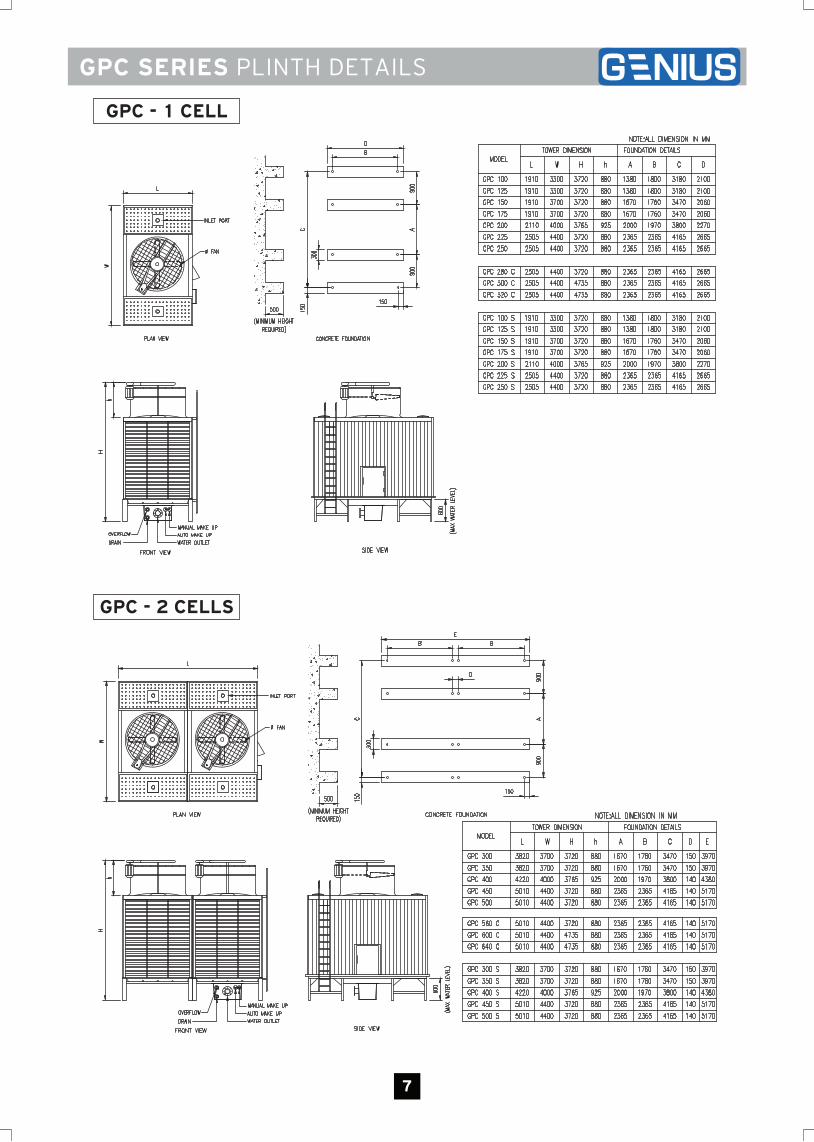
GPC SERIES PLINTH DETAILS
GPC - 1 CELL
GPC - 2 CELLS
8
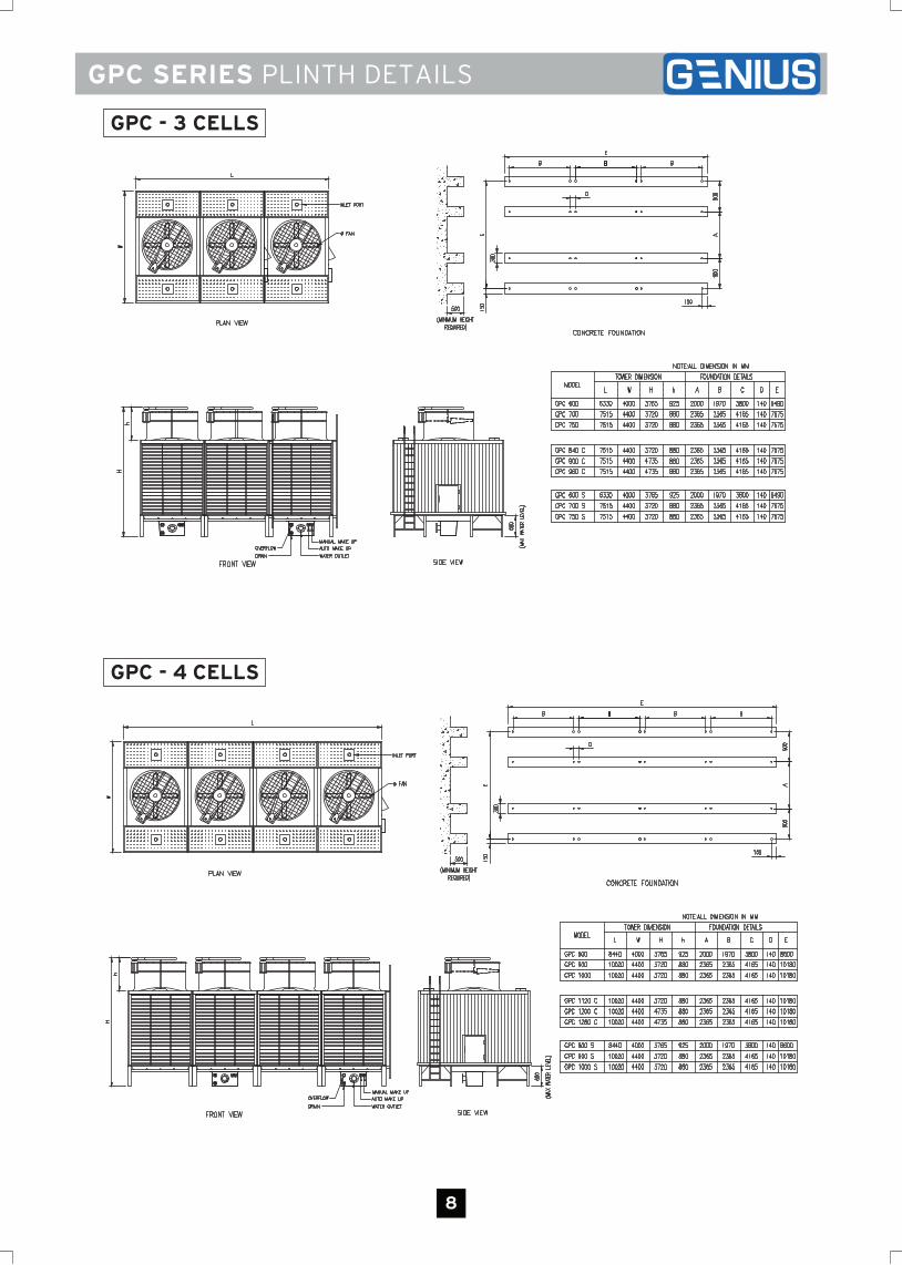
GPC SERIES PLINTH DETAILS
GPC - 3 CELLS
GPC - 4 CELLS
9
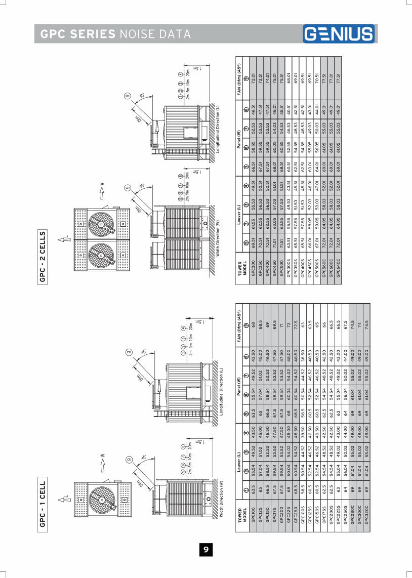
GPC SERIES NOISE DATAG
PC
- 1
CE
LL
FA
N (
Dfm
) (4
5°)
GP
C10
06
3.5
55
.54
49
.52
43
.50
63
.55
5.5
44
9.5
24
3.5
06
8
GP
C12
56
55
7.0
45
1.0
24
5.0
06
55
7.0
45
1.0
24
5.0
06
8.5
GP
C15
06
6.5
58
.54
52
.52
46
.50
66
.55
8.5
45
2.5
24
6.5
06
9
GP
C17
56
7.5
59
.54
53
.52
47
.50
67
.55
9.5
45
3.5
24
7.5
06
9.5
GP
C2
00
67
.55
9.5
45
3.5
24
7.5
06
7.5
59
.54
53
.52
47
.50
71
GP
C2
25
68
60
.04
54
.02
48
.00
68
60
.04
54
.02
48
.00
72
GP
C2
50
68
.56
0.5
45
4.5
24
8.5
06
8.5
60
.54
54
.52
48
.50
72
.5
GP
C10
0S
58
.55
0.5
44
4.5
23
8.5
05
8.5
50
.54
44
.52
38
.50
63
GP
C12
5S
60
.55
2.5
44
6.5
24
0.5
06
0.5
52
. 54
46
.52
40
.50
63
.5
GP
C15
0S
60
.55
2.5
44
6.5
24
0.5
06
0.5
52
.54
46
.52
40
.50
65
GP
C17
5S
62
.55
4.5
44
8.5
24
2.5
06
2.5
54
.54
48
.52
42
.50
66
GP
C2
00
S6
2.5
54
.54
48
.52
42
.50
62
.55
4.5
44
8.5
24
2.5
06
6.5
GP
C2
25
S6
35
5.0
44
9.0
24
3.0
06
35
5.0
44
9.0
24
3.0
06
6.5
GP
C2
50
S6
45
6.0
45
0.0
24
4.0
06
45
6.0
45
0.0
24
4.0
06
7.5
GP
C2
80
C6
96
1.0
45
5.0
24
9.0
06
96
1.0
45
5.0
24
9.0
07
4.5
GP
C3
00
C6
96
1.0
45
5.0
24
9.0
06
96
1.0
45
5.0
24
9.0
07
4
GP
C3
20
C6
96
1.0
45
5.0
24
9.0
06
96
1.0
45
5.0
24
9.0
07
4.5
TO
WE
R
MO
DE
L
Lou
ver
(L
)P
an
el (
W)
Wid
th D
ire
ctio
n (
W)
Lo
ng
itu
din
al D
ire
ctio
n (
L)
GP
C -
2 C
EL
LS
Wid
th D
ire
ctio
n (
W)
Lo
ng
itu
din
al D
ire
ctio
n (
L)
FA
N (
Dfm
) (4
5°)
GP
C3
00
69
.51
61.
55
55
.53
49
.51
66
.51
58
.55
52
.53
46
.51
72
.01
GP
C3
50
70
.51
62
.55
56
.53
50
.51
67
.51
59
.55
53
.53
47
.51
72
.51
GP
C4
00
70
.51
62
.55
56
.53
50
.51
67
.51
59
.55
53
.53
47
.51
74
.01
GP
C4
50
71.
01
63
.05
57
.03
51.
01
68
.01
60
.05
54
.03
48
.01
75
.01
GP
C5
00
71.
51
63
.55
57
.53
51.
51
68
.51
60
.55
54
.53
48
.51
75
.51
GP
C3
00
S6
3.5
15
5.5
54
9.5
34
3.5
16
0.5
15
2.5
54
6.5
34
0.5
16
8.0
1
GP
C3
50
S6
5.5
15
7.5
55
1.5
34
5.5
16
2.5
15
4.5
54
8.5
34
2.5
16
9.0
1
GP
C4
00
S6
5.5
15
7.5
55
1.5
34
5.5
16
2.5
15
4.5
54
8.5
34
2.5
16
9.5
1
GP
C4
50
S6
6.0
15
8.0
55
2.0
34
6.0
16
3.0
15
5.0
54
9.0
34
3.0
16
9.5
1
GP
C5
00
S6
7.0
15
9.0
55
3.0
34
7.0
16
4.0
15
6.0
55
0.0
34
4.0
17
0.5
1
GP
C5
60
C7
2.0
16
4.0
55
8.0
35
2.0
16
9.0
16
1.0
55
5.0
34
9.0
17
7.5
1
GP
C6
00
C7
2.0
16
4.0
55
8.0
35
2.0
16
9.0
16
1.0
55
5.0
34
9.0
17
7.0
1
GP
C6
40
C7
2.0
16
4.0
55
8.0
35
2.0
16
9.0
16
1.0
55
5.0
34
9.0
17
7.5
1
TO
WE
R
MO
DE
L
Lou
ver
(L
)P
an
el (
W)
10
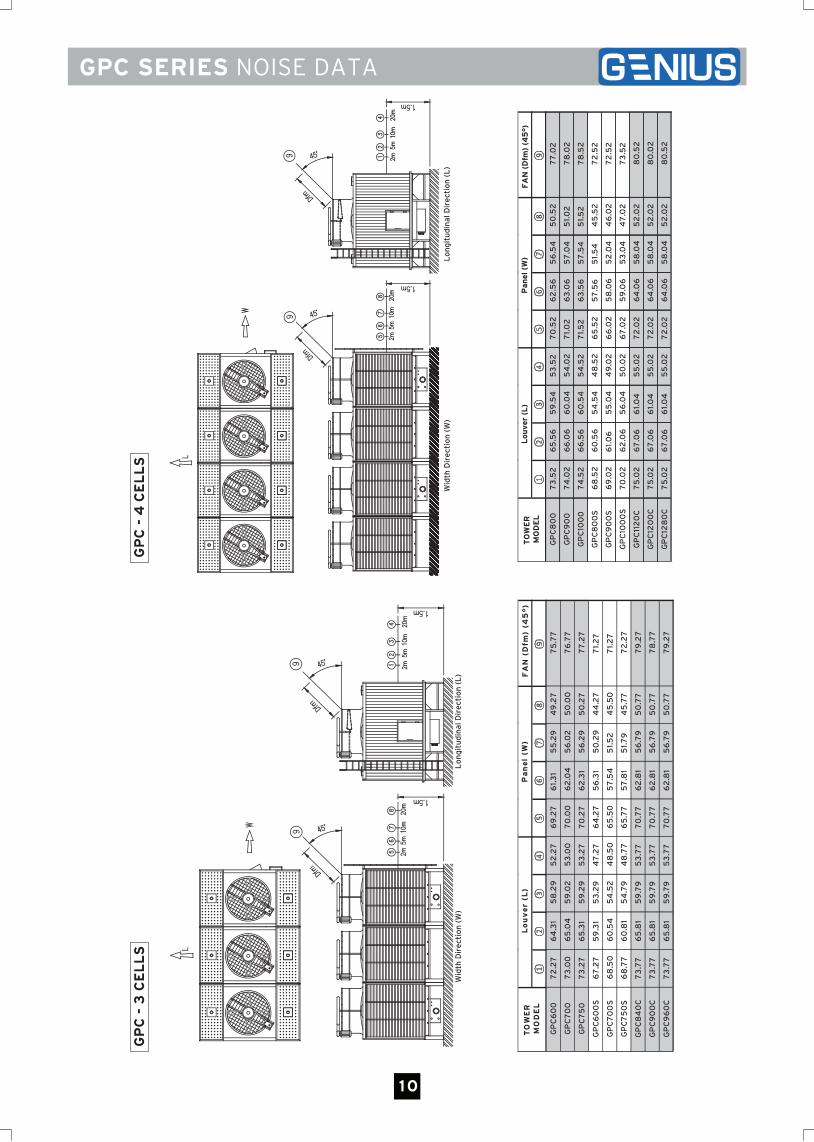
GPC SERIES NOISE DATA
GP
C -
3 C
EL
LS
Lo
ng
itu
din
al D
ire
ctio
n (
L)
Wid
th D
ire
ctio
n (
W)
FA
N (
Dfm
) (4
5°)
GP
C6
00
72
.27
64
.31
58
.29
52
.27
69
.27
61.
31
55
.29
49
.27
75
.77
GP
C7
00
73
.00
65
.04
59
.02
53
.00
70
.00
62
.04
56
.02
50
.00
76
.77
GP
C7
50
73
.27
65
.31
59
.29
53
.27
70
.27
62
.31
56
.29
50
.27
77
.27
GP
C6
00
S6
7.2
75
9.3
15
3.2
94
7.2
76
4.2
75
6.3
15
0.2
94
4.2
77
1.2
7
GP
C7
00
S6
8.5
06
0.5
45
4.5
24
8.5
06
5.5
05
7.5
45
1.5
24
5.5
07
1.2
7
GP
C7
50
S6
8.7
76
0.8
15
4.7
94
8.7
76
5.7
75
7.8
15
1.7
94
5.7
77
2.2
7
GP
C8
40
C7
3.7
76
5.8
15
9.7
95
3.7
77
0.7
76
2.8
15
6.7
95
0.7
77
9.2
7
GP
C9
00
C7
3.7
76
5.8
15
9.7
95
3.7
77
0.7
76
2.8
15
6.7
95
0.7
77
8.7
7
GP
C9
60
C7
3.7
76
5.8
15
9.7
95
3.7
77
0.7
76
2.8
15
6.7
95
0.7
77
9.2
7
TO
WE
R
MO
DE
L
Lo
uv
er
(L)
Pa
ne
l (W
)
GP
C -
4 C
EL
LS
Lo
ng
itu
din
al D
ire
ctio
n (
L)
Wid
th D
ire
ctio
n (
W)
FA
N (
Dfm
) (4
5°)
GP
C8
00
73
.52
65
.56
59
.54
53
.52
70
.52
62
.56
56
.54
50
.52
77
.02
GP
C9
00
74
.02
66
.06
60
.04
54
.02
71.
02
63
.06
57
.04
51.
02
78
.02
GP
C10
00
74
.52
66
.56
60
.54
54
.52
71.
52
63
.56
57
.54
51.
52
78
.52
GP
C8
00
S6
8.5
26
0.5
65
4.5
44
8.5
26
5.5
25
7.5
65
1.5
44
5.5
27
2.5
2
GP
C9
00
S6
9.0
26
1.0
65
5.0
44
9.0
26
6.0
25
8.0
65
2.0
44
6.0
27
2.5
2
GP
C10
00
S7
0.0
26
2.0
65
6.0
45
0.0
26
7.0
25
9.0
65
3.0
44
7.0
27
3.5
2
GP
C11
20
C7
5.0
26
7.0
66
1.0
45
5.0
27
2.0
26
4.0
65
8.0
45
2.0
28
0.5
2
GP
C12
00
C7
5.0
26
7.0
66
1.0
45
5.0
27
2.0
26
4. 0
65
8.0
45
2.0
28
0.0
2
GP
C12
80
C7
5.0
26
7.0
66
1.0
45
5.0
27
2.0
26
4.0
65
8.0
45
2.0
28
0.5
2
TO
WE
R
MO
DE
L
Lou
ver
(L
)P
an
el (
W)
RECOMMENDED COOLING TOWER ARRANGEMENT
11
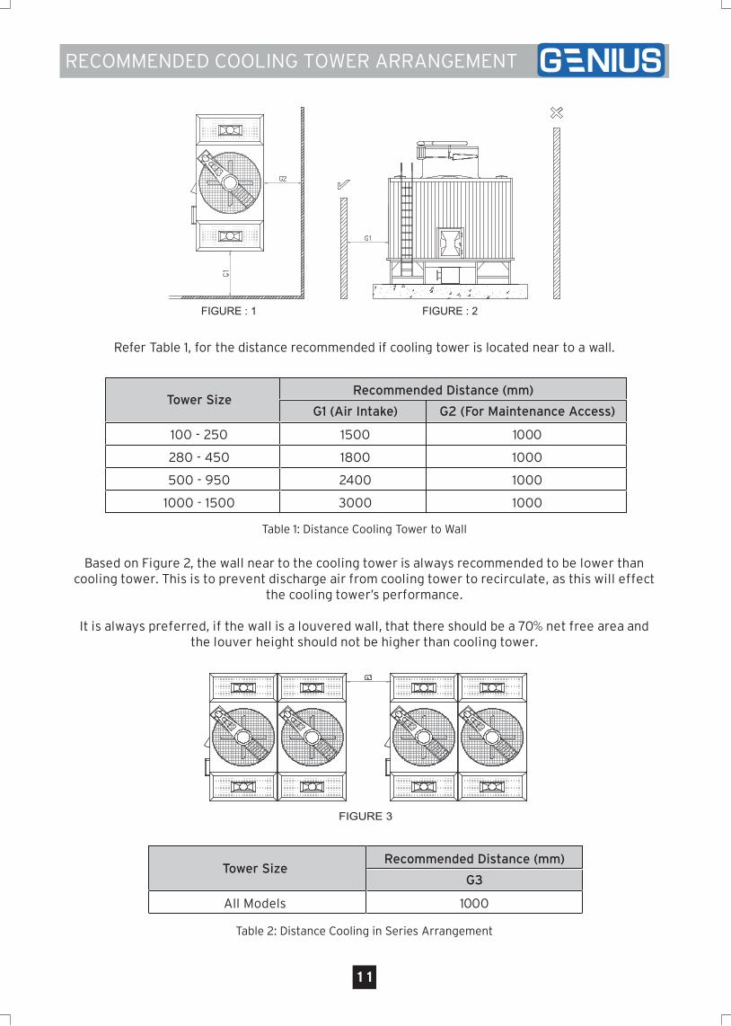
Refer Table 1, for the distance recommended if cooling tower is located near to a wall.
Based on Figure 2, the wall near to the cooling tower is always recommended to be lower than cooling tower. This is to prevent discharge air from cooling tower to recirculate, as this will effect
the cooling tower’s performance.
It is always preferred, if the wall is a louvered wall, that there should be a 70% net free area and the louver height should not be higher than cooling tower.
Table 1: Distance Cooling Tower to Wall
Table 2: Distance Cooling in Series Arrangement
Recommended Distance (mm)Tower Size
G3
All Models 1000
Recommended Distance (mm)Tower Size
G1 (Air Intake)
100 - 250
280 - 450
500 - 950
1500
1800
2400
1000 - 1500 3000
G2 (For Maintenance Access)
1000
1000
1000
1000
FIGURE : 1 FIGURE : 2
FIGURE 3
12
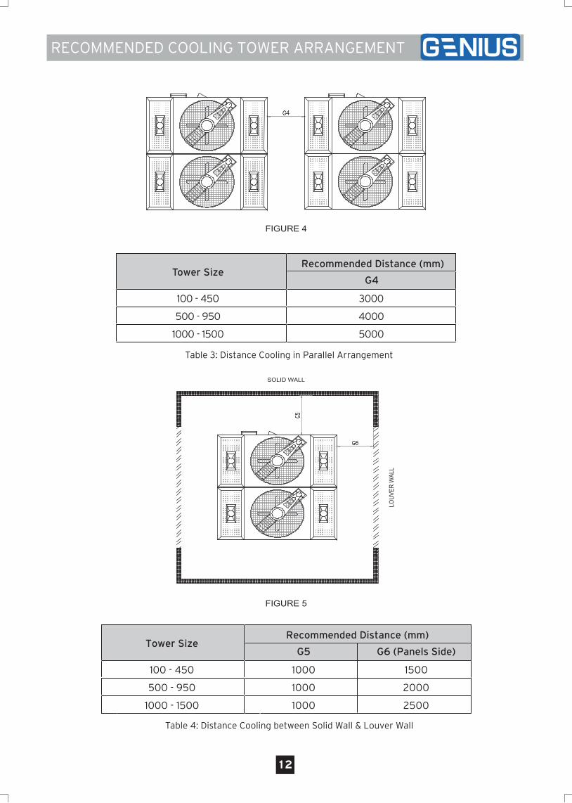
Table 3: Distance Cooling in Parallel Arrangement
Recommended Distance (mm)Tower Size
G4
100 - 450
500 - 950
1000 - 1500
3000
4000
5000
Table 4: Distance Cooling between Solid Wall & Louver Wall
Recommended Distance (mm)Tower Size
G5
100 - 450
500 - 950
1000 - 1500
1000
1000
1000
G6 (Panels Side)
1500
2000
2500
RECOMMENDED COOLING TOWER ARRANGEMENT
FIGURE 4
FIGURE 5
SOLID WALL
LOUV
ER W
ALL
13
SPECIAL OPTIONS
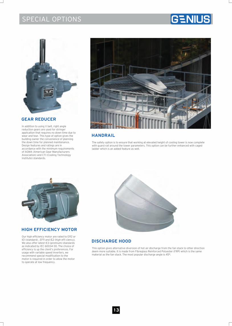
GEAR REDUCER
In addition to using V belt, right angle reduction gears are used for stringer application that requires no down time due to wear and tear. This type of option gives the building owner the convenience of planning the down time for planned maintenance. Design features and ratings are in accordance with the minimum requirements of AGMA (American Gear Manufacturers Association) and CTI (Cooling Technology Institute) standards.
HANDRAIL
The safety option is to ensure that working at elevated height of cooling tower is now complete with guard rail around the tower parameters. This option can be further enhanced with caged ladder which is an added feature as well.
HIGH EFFICIENCY MOTOR
Our high efficiency motor are rated to Eff2 or IE1 (standard) , EFf1 and IE2 (high effi ciency). We also offer latest IE3 (premium) standards as indicated by IEC 60034-30. The choice of efficiency is up the client’s preferences. For usage with variable speed inverters, we recommend special modification to the motor is required in order to allow the motor to operate at low frequency.
DISCHARGE HOOD
This option gives alternative diversion of hot air discharge from the fan stack to other direction deem more suitable. It is made from Fibreglass Reinforced Polyester (FRP) which is the same material as the fan stack. The most popular discharge angle is 45º.
CALCULATION OF MAKE UP WATER
14
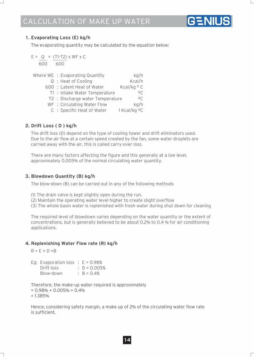
2. Drift Loss ( D ) kg/h
The drift loss (D) depend on the type of cooling tower and drift eliminators used.Due to the air flow at a certain speed created by the fan, some water droplets arecarried away with the air, this is called carry-over loss.
There are many factors affecting the figure and this generally at a low level,approximately 0.005% of the normal circulating water quantity.
3. Blowdown Quantity (B) kg/h
The blow-down (B) can be carried out in any of the following methods
(1) The drain valve is kept slightly open during the run.(2) Maintain the operating water level higher to create slight overflow(3) The whole basin water is replenished with fresh water during shut down for cleaning
The required level of blowdown varies depending on the water quantity or the extent ofconcentrations, but is generally believed to be about 0.2% to 0.4 % for air conditioningapplications.
4. Replenishing Water Flow rate (R) kg/h
R = E + D +B
Therefore, the make-up water required is approximately= 0.98% + 0.005% + 0.4%= 1.385%
Hence, considering safety margin, a make up of 2% of the circulating water flow rateis sufficient.
Eg: Evaporation lossDrift lossBlow-down
:::
E = 0.98%D = 0.005%B = 0.4%
1. Evaporating Loss (E) kg/h
The evaporating quantity may be calculated by the equation below:
Where WEQ
600T1T2WF
C
: Evaporating Quantity: Heat of Cooling: Latent Heat of Water: Intake Water Temperature: Discharge water Temperature: Circulating Water Flow: Specific Heat of Water
kg/hKcal/h
Kcal/kg º CºCºC
kg/h1 Kcal/kg ºC
E = Q = (T1-T2) x WF x C
600 600
V1.0 07/2017