development of three phase induction motor · pdf filedevelopment of three phase induction...
TRANSCRIPT
DEVELOPMENT OF THREE PHASE INDUCTION
MOTOR CONTROLLER
AHMAD FAKHRUZZAMAN B M ZAWAWI
This report is submitted as partial fulfillment of the
Requirement for the award of the
Bachelor Degree of Electrical Engineering (Power system)
Faculty of Electrical & Electronics Engineering
University Malaysia Pahang
OCTOBER 2009
“I hereby acknowledge that the scope and quality of this report is qualified for the award
of the Bachelor Degree of Electrical Engineering (Power System)”
Signature :_________________________
Author : ROSMADI BIN ABDULLAH
Date : 22 NOV 2009
“All the trademark and copyrights use herein are property of their respective owner.
References of information from other sources are quoted accordingly; otherwise the
information presented in this report is solely work of the author”
Signature :_________________________
Author : AHMAD FAKHRUZZAMAN B M ZAWAWI
Date : 22 NOV 2009
ACKNOWLEDGEMENT
First of all I would like to thank God the Almighty for his bless and for
giving me body and mental strength for me to be able to finished my final project in time
as a partial fulfillment of the requirement of the degree of Bachelor Engineering
(Electrical & Electronic).
Secondly, I would like to thanks all the people who had assist me directly and
indirectly for helping me to complete this project. My first gratitude is goes to Mr
Rosmadi Abdullah, my supervisor for this project that had help me and give full support,
advice and guide to the end of the project. I have learned many thing from him and
without him, I could not finish this project.
Very special thanks also to all technicians, lab assistance for helping me with all
the work at the lab and for their full co-operation.
Last but not least, I would like to thank to my parent and friends that gave me lot
of moral support while I was doing this project.
ABSTRACT
The development of induction motor controller project is a part of three phase
induction motor control system that will be designed based on microcontroller using
MC68HC908MR32 integrated circuit manufactured by Motorola. This controller board
is an integral part of embedded motion control series and will be interface with power
circuit stage, optoisolator and emulator as one system to control a three phase induction
motor speed by controlling the PWM output using microcontroller program. The
controlled PWM output then will be transfer to power circuit board that consist of
power inverter switching to control the speed of the three phase motor. This method is
called V/F control method. This control board is equipped with overcurrent circuit
sensor to detect fault for safety purpose and tachometer circuit to sense motor speed.
This control board also have forward/reverse switch, start/stop switch and speed control
pot.
ABSTRAK
Penambahbaikan sidtem kawalan motor tiga fasa yang akan dijalankan di dalam projek
ini adalah berdasarkan penggunaan “microcontroller” yang dikeluarkan oleh Motorola.
“Contoller Board” ini adalah sebahagian daripada siri kawalan dimana ianya akan
disambung kepada litar kuasa, litar “optoisolator” dan litar “emulator” sebagai sati
system kawalan untuk mengawal kelajuan motor tiga fasa dengan menggunakan isyarat
PWM. Isyarat PWM yang dikawal kemudiannya dihantar kepada litar kuasa yang
mengandungi penyongsang arus yang akan mengawal kelajuan motor, kaedah ini
dipanggil kawalan voltan dan frequency (V/F). “controller board” ini juga mempunyai
litar pengesan kelajuan serta litar pengesan arus berlebihan bagi tujuan keselamatan.
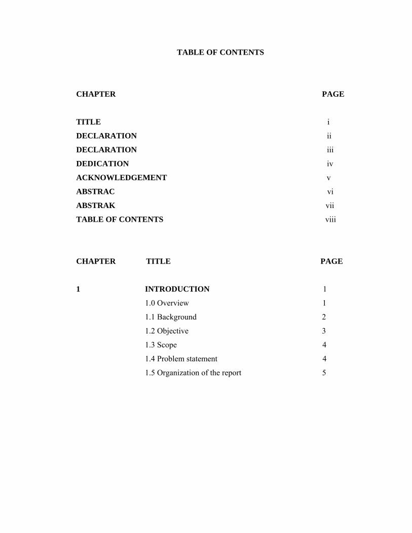
TABLE OF CONTENTS
CHAPTER PAGE
TITLE i
DECLARATION ii
DECLARATION iii
DEDICATION iv
ACKNOWLEDGEMENT v
ABSTRAC vi
ABSTRAK vii
TABLE OF CONTENTS viii
CHAPTER TITLE PAGE
1 INTRODUCTION 1
1.0 Overview 1
1.1 Background 2
1.2 Objective 3
1.3 Scope 4
1.4 Problem statement 4
1.5 Organization of the report 5
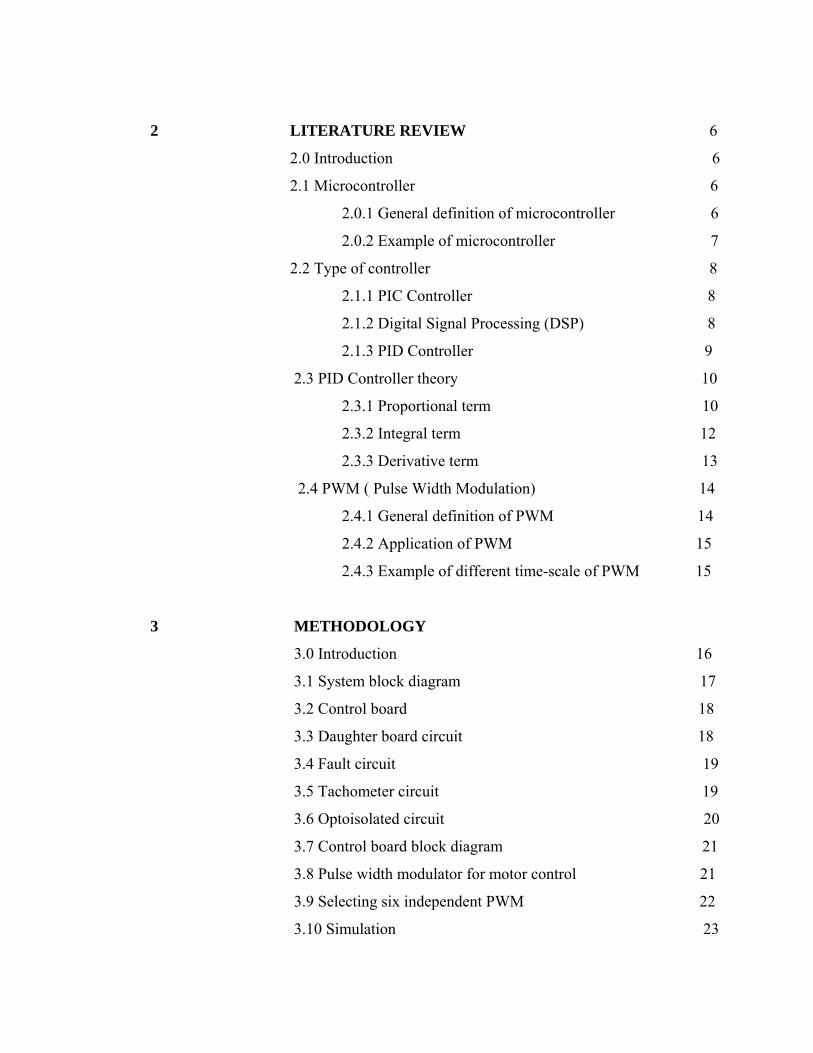
2 LITERATURE REVIEW 6
2.0 Introduction 6
2.1 Microcontroller 6
2.0.1 General definition of microcontroller 6
2.0.2 Example of microcontroller 7
2.2 Type of controller 8
2.1.1 PIC Controller 8
2.1.2 Digital Signal Processing (DSP) 8
2.1.3 PID Controller 9
2.3 PID Controller theory 10
2.3.1 Proportional term 10
2.3.2 Integral term 12
2.3.3 Derivative term 13
2.4 PWM ( Pulse Width Modulation) 14
2.4.1 General definition of PWM 14
2.4.2 Application of PWM 15
2.4.3 Example of different time-scale of PWM 15
3 METHODOLOGY
3.0 Introduction 16
3.1 System block diagram 17
3.2 Control board 18
3.3 Daughter board circuit 18
3.4 Fault circuit 19
3.5 Tachometer circuit 19
3.6 Optoisolated circuit 20
3.7 Control board block diagram 21
3.8 Pulse width modulator for motor control 21
3.9 Selecting six independent PWM 22
3.10 Simulation 23
3.10.1 Assembling & configuring simulation block 23
3.11 Printed circuit board design(PCB) 24
3.12 Generating gerber file 26
4 RESULT AND DISCUSSION
4.0 Introduction 30
4.1 Printed circuit board 30
4.2 Matlab simulation 36
4.2.1 System block diagram 36
5 CONCLUSION AND FUTURE WORK
5.0 Conclusion 38
5.1 Future Works and Recommendations 38
REFERENCES 39
APPENDIX 41
CHAPTER 1
INTRODUCTION
1.0 Overview
As the prices of the power electronic devices are getting cheaper and widely used
in various applications like induction motor controllers, automation, inverters and so on.
There are many types of digital controller like a microprocessor, microcontroller and
DSP (digital signal processing) are widely used to control algorithm in motor controller.
PID, Fuzzy logic, and neural network are the examples of algorithm techniques used in
induction motor drive applications. This project was developed with an induction motor
controller that use PID controller (proportional–integral–derivative controller) in
microcontroller. The PID controller is widely used in the induction motor drive
applications due to its simplicity in structure, superior robustness, and familiarity to most
field operators. The key issue in designing PID controller for the induction motor drive
is to settle the gains so that the controller works well in every condition [5]. Especially
in applications like in induction motor controllers not only the frequency, but the
magnitude of the voltage needs to be varied [3]. For these kinds of applications pulse
width modulated (PWM) are more suitable [3]. The speed of induction motor was varied
by controlling the PWM output using microcontroller program.
1.1 Background
A proportional–integral–derivative controller (PID controller) is a generic control loop
feedback mechanism (controller) widely used in industrial control systems. A PID
controller attempts to correct the error between a measured process variable and a
desired setpoint by calculating and then outputting a corrective action that can adjust the
process accordingly [6].
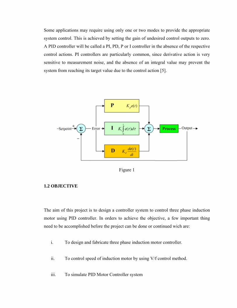
The PID controller calculation (algorithm) involves three separate parameters; Figure1
shows Proportional, the Integral and Derivative values. The Proportional value
determines the reaction to the current error, the Integral value determines the reaction
based on the sum of recent errors, and the Derivative value determines the reaction based
on the rate at which the error has been changing. The weighted sum of these three
actions is used to adjust the process via a control element such as the position of a
control valve or the power supply of a heating element [6].
By "tuning" the three constants in the PID controller algorithm, the controller can
provide control action designed for specific process requirements. The response of the
controller can be described in terms of the responsiveness of the controller to an error,
the degree to which the controller overshoots the setpoint and the degree of system
oscillation. Note that the use of the PID algorithm for control does not guarantee optimal
control of the system or system stability [5].
S
s
A
c
s
s
1
T
m
n
Some applic
system contr
A PID contr
control actio
sensitive to
system from
1.2 OBJEC
The aim of t
motor using
need to be ac
i. T
ii. T
iii. T
cations may
rol. This is a
roller will be
ons. PI cont
measuremen
m reaching its
TIVE
this project
g PID contro
ccomplished
To design an
To control sp
To simulate P
require usin
achieved by
e called a PI,
trollers are p
nt noise, an
s target value
is to design
oller. In ord
d before the p
nd fabricate t
peed of induc
PID Motor C
ng only one
setting the g
, PD, P or I c
particularly
nd the absen
e due to the
Figure 1
a controller
ders to achie
project can b
three phase i
ction motor
Controller sy
or two mod
gain of unde
controller in
common, si
nce of an int
control actio
1
r system to c
eve the obje
be done or c
induction mo
by using V/f
ystem
des to provid
esired contro
the absence
nce derivati
tegral value
on [5].
control three
ective, a few
continued wi
otor controll
f control me
de the approp
ol outputs to
e of the respe
ive action is
may preven
e phase indu
w important
ch are:
er.
ethod.
priate
zero.
ective
s very
nt the
uction
thing
1.3 SCOPE
This project is focused on two major parts, the hardware and software development. In
this project, there are four scopes that were proposed such as below:
i. To design PCB for motor controller board
ii. To simulate PID controller using Matlab
iii. To test the controller using PID algorithm for three phase induction motor.
iv. To analyze the performance of the motor controller based on the simulation
result
1.4 PROBLEM STATEMENT
Three-phase induction motors have three salient poles per pole number, so a four-pole
motor would have twelve salient poles. This allows the motor to produce a rotating field,
allowing the motor to start with no extra equipment and run more efficiently than a
similar single-phase motor. The synchronous rotational speed of the rotor is controlled
by the number of pole pairs (number of windings in the stator) and by the frequency of
the supply voltage. It was difficult to vary the frequency to the motor and therefore the
uses for the induction motor were limited. The general term for a power electronic
device that controls the speed of motor as well as other parameters is inverter. A typical
unit will take the mains AC supply, rectify and smooth it into a "link" DC voltage, and,
then convert it into the desired AC waveform. In general, a DC-to-AC converter is called
an inverter, which is probably where the motor-control inverter gets its name. Because
the induction motor has no brushes and is easy to control, many older DC motors are
being replaced with induction motors and accompanying inverters in industrial
applications. But in order to control the switching of power transistor in the inverter, we
need to supply PWM signal to the power transistor. To generate this PWM signal, we
need to design a controller for example PID controller.
1.5 Organization of the report
There are all five chapters being structures in this repot and every chapter will
elaborate in detail about this project. For the first chapter, an overview about this project,
three phase induction motor controller using PID is discussed including the objectives,
scope and problem statement. This overview is used as a guide line to develop the three
phase induction motor controller.
Chapter 2 will explain and discuss on the literature review of the three phase
induction motor controller. It also focuses on the general introduction of the controller
used. It gives a brief review about the types of controller, and its application in
controlling three phase induction motor.
Chapter 3 discusses the methodologies of the controller board that has been
applied in completing this project. This chapter gives a detail discussion on the design of
the hardware of the systems and the detail explanation and method of creating the
printed circuit board (PCB) of the control board. Furthermore, this chapter discuss in
detail how the control board work and what method it used to control the speed of three
phase induction motor.
Chapter 4 discuss about various testing and results that are conducted to each
module of the project. This chapter also concludes the PCB board of the control board
including the simulation result of the PWM motor control system using Matlab software.
All discussions are concentrated on the result and the overall performance of the three
phase inverter.
Lastly, Chapter 5 is discussing on the conclusion and summary of the
development of three phase induction motor controller completed project. Some
recommendation and system upgrades are also discussed.
CHAPTER 2
LITERATURE REVIEW
2.0 Introduction
This report involved the design and research regarding on three phase induction
motor controller. In this chapter, the researcher’s review articles and past research about
the theory and methods were used in developing three phase induction motor controller.
2.1 Microcontroller
2.1.1 General definitions of microcontroller
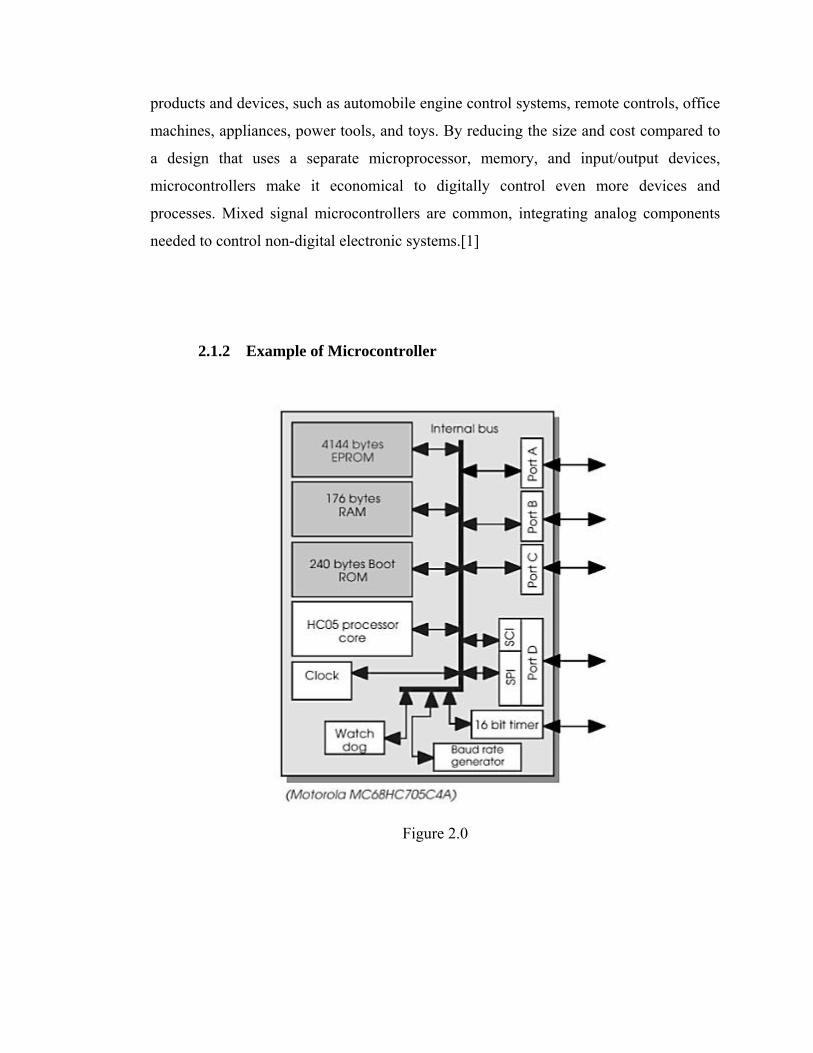
Microcontrollers is a small computer on a single integrated circuit consisting of a
relatively simple CPU combined with support functions such as a crystal oscillator,
timers, watchdog timer, serial and analog I/O etc. it is used in automatically controlled
products and devices, such as automobile engine control systems, remote controls, office
machines, appliances, power tools, and toys. By reducing the size and cost compared to
a design that uses a separate microprocessor, memory, and input/output devices,
microcontrollers make it economical to digitally control even more devices and
processes. Mixed signal microcontrollers are common, integrating analog components
needed to control non-digital electronic systems.[1]
2.1.2 Example of Microcontroller
Figure 2.0
2.2 Type of controller
2.2.1 PIC Controller
PIC is a family of Harvard architecture microcontrollers made by Microchip
Technology, derived from the PIC1640[7] originally developed by General Instrument's
Microelectronics Division. The name PIC initially referred to "Peripheral Interface
Controller".[8][9]
PICs are popular with both industrial developers and hobbyists alike due to their low
cost, wide availability, large user base, extensive collection of application notes,
availability of low cost or free development tools, and serial programming (and re-
programming with flash memory) capability.
2.2.2 Digital signal processing (DSP)
Digital signal processing (DSP) is concerned with the representation of the signals by a
sequence of numbers or symbols and the processing of these signals. Digital signal
processing and analog signal processing are subfields of signal processing. DSP includes
subfields like: audio and speech signal processing, sonar and radar signal processing,
sensor array processing, spectral estimation, statistical signal processing, digital image
processing, signal processing for communications, biomedical signal processing, seismic
data processing, etc.
Since the goal of DSP is usually to measure or filter continuous real-world analog
signals, the first step is usually to convert the signal from an analog to a digital form, by
using an analog to digital converter. Often, the required output signal is another analog
output signal, which requires a digital to analog converter.
DSP algorithms have long been run on standard computers, on specialized processors
called digital signal processors (DSPs), or on purpose-built hardware such as
application-specific integrated circuit (ASICs). Today there are additional technologies
used for digital signal processing including more powerful general purpose
microprocessors, field-programmable gate arrays (FPGAs), digital signal controllers
(mostly for industrial apps such as motor control), and stream processors, among
others.[3]
2.2.3 PID controller
The majority of control systems in the world are operated by proportional-
integral-derivative (PID) controllers. Indeed, it has been reported that 98% of the control
loops in the pulp and paper industries are controlled by single-input single output PI
controllers [2] and that in process control applications, more than 95% of the controllers
are of the PID type [4]. Similar statistics hold in the motion control and aerospace
industries.
The PID controller calculation (algorithm) involves three separate parameters;
the proportional, the integral and derivative values. The proportional value determines
the reaction to the current error, the integral value determines the reaction based on the
sum of recent errors, and the derivative value determines the reaction based on the rate at
which the error has been changing. The weighted sum of these three actions is used to
adjust the process via a control element such as the position of a control valve or the
power supply of a heating element.
By tuning the three constants in the PID controller algorithm, the controller can provide
control action designed for specific process requirements. The response of the controller
can be described in terms of the responsiveness of the controller to an error, the degree
to which the controller overshoots the setpoint and the degree of system oscillation. Note
that the use of the PID algorithm for control does not guarantee optimal control of the
system or system stability.
Some applications may require using only one or two modes to provide the appropriate
system control. This is achieved by setting the gain of undesired control outputs to zero.
A PID controller will be called a PI, PD, P or I controller in the absence of the respective
control actions. PI controllers are particularly common, since derivative action is very
sensitive to measurement noise, and the absence of an integral value may prevent the
system from reaching its target value due to the control action.[5]
2.3 PID controller theory
The PID control scheme is named after its three correcting terms, whose sum constitutes
the manipulated variable (MV). Hence:
where
Pout, Iout, and Dout are the contributions to the output from the PID controller from each
of the three terms, as defined below.
2.3.1 Proportional term
The proportional term (sometimes called gain) makes a change to the output that is
proportional to the current error value. The proportional response can be adjusted by
multiplying the error by a constant Kp, called the proportional gain.
The proportional term is given by:
where
Pout: Proportional term of output
Kp: Proportional gain, a tuning parameter
e: Error = SP − PV
t: Time or instantaneous time (the present)
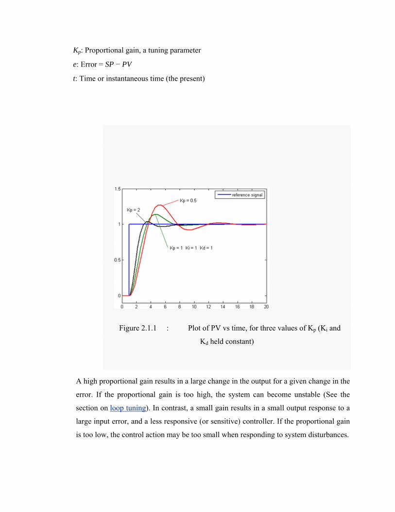
Figure 2.1.1 : Plot of PV vs time, for three values of Kp (Ki and
Kd held constant)
A high proportional gain results in a large change in the output for a given change in the
error. If the proportional gain is too high, the system can become unstable (See the
section on loop tuning). In contrast, a small gain results in a small output response to a
large input error, and a less responsive (or sensitive) controller. If the proportional gain
is too low, the control action may be too small when responding to system disturbances.
In the absence of disturbances, pure proportional control will not settle at its target
value, but will retain a steady state error that is a function of the proportional gain and
the process gain. Despite the steady-state offset, both tuning theory and industrial
practice indicate that it is the proportional term that should contribute the bulk of the
output change.
2.3.2 Integral term
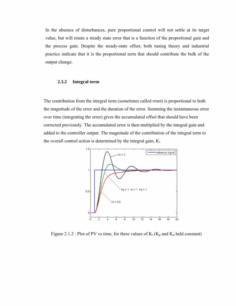
The contribution from the integral term (sometimes called reset) is proportional to both
the magnitude of the error and the duration of the error. Summing the instantaneous error
over time (integrating the error) gives the accumulated offset that should have been
corrected previously. The accumulated error is then multiplied by the integral gain and
added to the controller output. The magnitude of the contribution of the integral term to
the overall control action is determined by the integral gain, Ki.
Figure 2.1.2 : Plot of PV vs time, for three values of Ki (Kp and Kd held constant)
T
w
I
K
e
t
τ
T
p
p
a
v
f
o
The integral
where
Iout: Integral
Ki: Integral g
e: Error = SP
t: Time or in
τ: a dummy
The integral
process towa
proportional
accumulated
value (cross
further note
on loop tunin
2.3.3
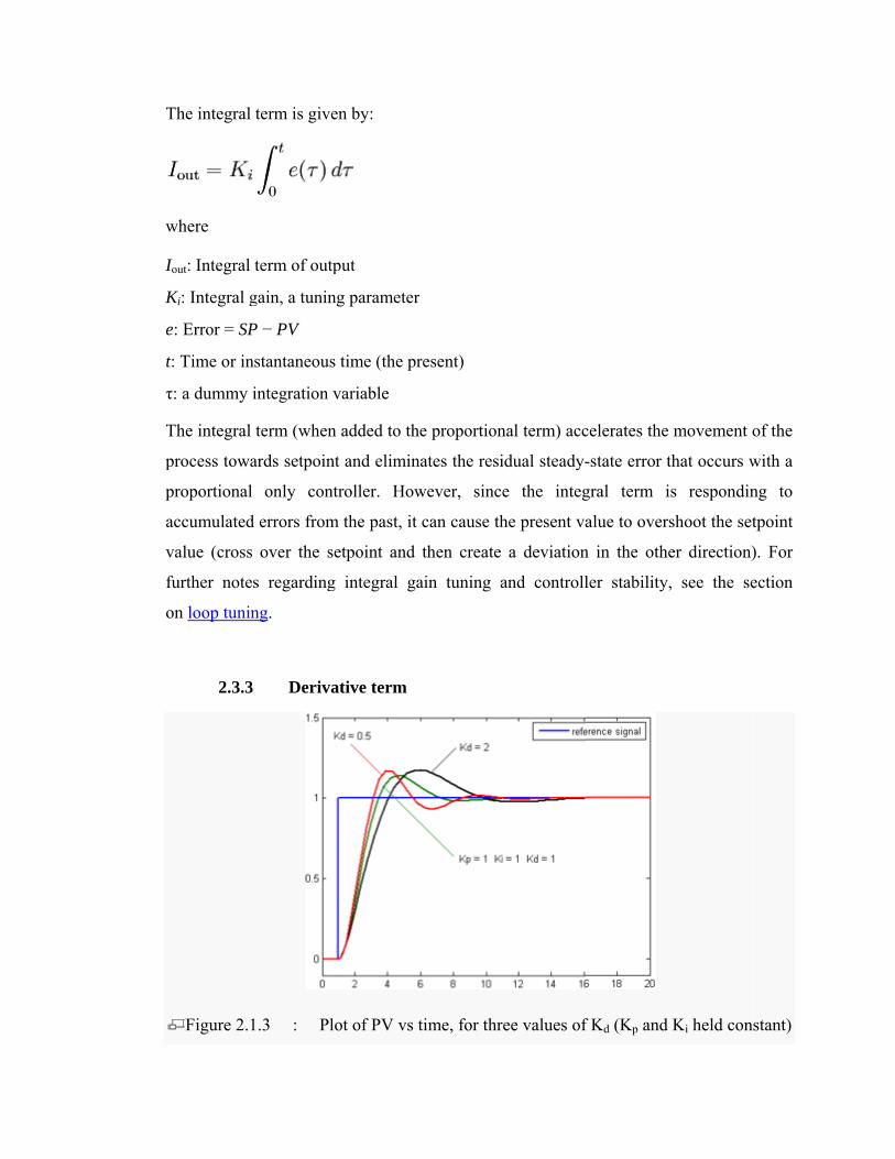
Figure 2.1
term is give
term of outp
gain, a tunin
P − PV
nstantaneous
integration v
term (when
ards setpoint
l only cont
d errors from
s over the se
es regarding
ng.
3 Deriva
1.3 : Plo
en by:
put
ng parameter
s time (the pr
variable
n added to th
t and elimin
troller. How
m the past, it
etpoint and
g integral ga
ative term
ot of PV vs t
r
resent)
he proportion
nates the resi
wever, sinc
can cause th
then create
ain tuning a
time, for thr
nal term) acc
idual steady-
e the integ
he present va
a deviation
and controll
ree values of
celerates the
-state error t
gral term i
alue to overs
n in the othe
ler stability,
f Kd (Kp and
movement o
that occurs w
s respondin
shoot the set
er direction)
, see the se
Ki held con
of the
with a
ng to
tpoint
). For
ection
stant)
The rate of change of the process error is calculated by determining the slope of the error
over time (i.e., its first derivative with respect to time) and multiplying this rate of
change by the derivative gain Kd. The magnitude of the contribution of the derivative
term (sometimes called rate) to the overall control action is termed the derivative
gain, Kd.
The derivative term is given by:
where
Dout: Derivative term of output
Kd: Derivative gain, a tuning parameter
e: Error = SP − PV
t: Time or instantaneous time (the present)
The derivative term slows the rate of change of the controller output and this effect is
most noticeable close to the controller setpoint. Hence, derivative control is used to
reduce the magnitude of the overshoot produced by the integral component and improve
the combined controller-process stability. However, differentiation of a signal amplifies
noise and thus this term in the controller is highly sensitive to noise in the error term,
and can cause a process to become unstable if the noise and the derivative gain are
sufficiently large.
2.4 PWM (pulse width modulation)
2.4.1 General definitions of PWM
Pulse-width modulation (PWM) is a very efficient way of providing intermediate
amounts of electrical power between fully on and fully off. A simple power switch with
a typical power source provides full power only, when switched on. PWM is a
comparatively-recent technique, made practical by modern electronic power switches.
The term duty cycle describes the proportion of on time to the regular interval or period
of time; a low duty cycle corresponds to low power, because the power is off for most of
the time. Duty cycle is expressed in percent, 100% being fully on. PWM works well
with digital controls, which, because of their on/off nature, can easily set the needed duty
cycle.[10]
2.4.2 Application of PWM
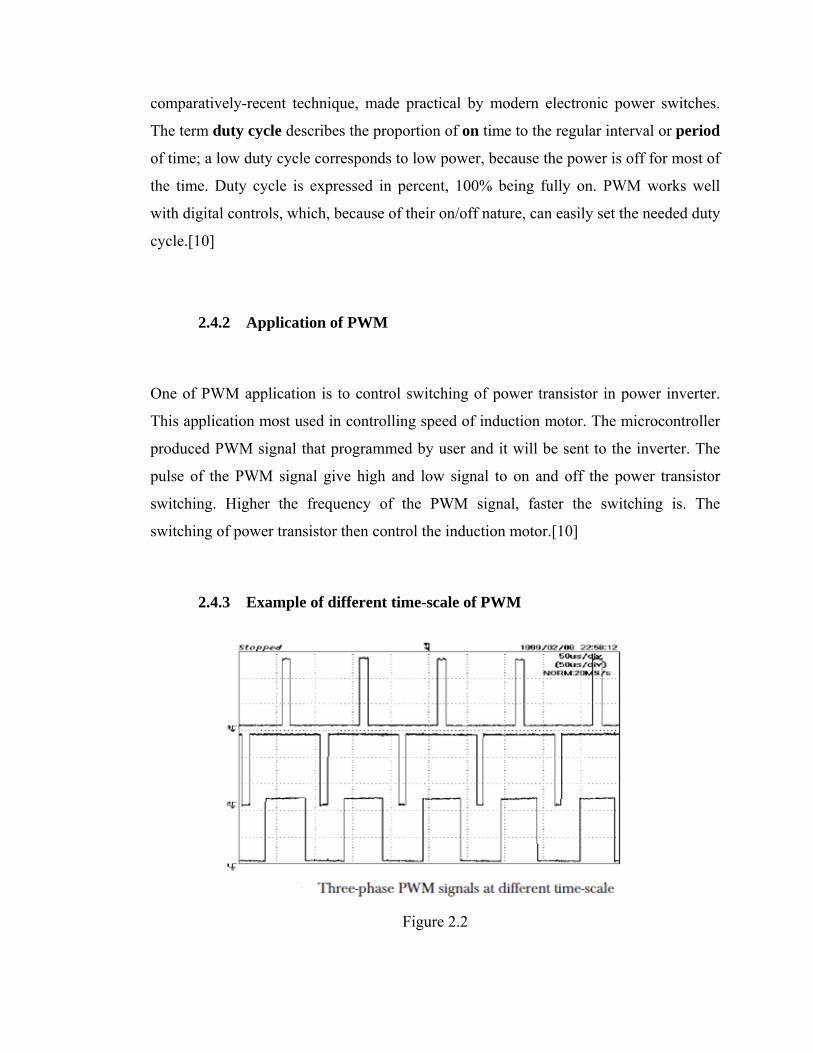
One of PWM application is to control switching of power transistor in power inverter.
This application most used in controlling speed of induction motor. The microcontroller
produced PWM signal that programmed by user and it will be sent to the inverter. The
pulse of the PWM signal give high and low signal to on and off the power transistor
switching. Higher the frequency of the PWM signal, faster the switching is. The
switching of power transistor then control the induction motor.[10]
2.4.3 Example of different time-scale of PWM
Figure 2.2