communication vii a subroutine package for solving ... papers/pert vol. 14 (3) dec. 1991/20... · a...
TRANSCRIPT
PERTANIKA 14(3), 359-371 (1991)
COMMUNICATION VII
A Subroutine Package for Solving Hydrodynamic Lubrication Problems
ABSTRAK
Kertas-kerja ini membentangkan satu perisian subrutin untuk menyelesaikan masalah pelindr hidrodinamik yanglyeroperasi dibawah saput sesuhu. A nalisis dan algoritma pengiraanjuga diterangkan. Kaedah unsur terhingga telahdigunakan untuk menyelesaikan kedua-dua kes aliran lamina dangelora. Satu contohgalas jara susuk tiga cupingdigunakan untuk menunjukkan penggunaan perisian subrutin ini.
ABSTRACT
The paper presents a subroutine package that solves theproblem of hydrodynamic lubrication operating under isothermalfilm. The underlying analysis and computational algorithm are described. The finite element method was used forsolving the pressure equation for cases of both laminar and turbulent flow. A representative example of a three-lobe profilebore bearing is used to demonstrate the application of the subroutine package..
INTRODUCTION
The need to reduce machinery failure andmaintenance costs while simultaneously increasingtheir power output and efficiency has led tonumerous studies on ways of improvingperformance, reliability and life expectancy of criticalmachine elements. This has resulted in muchdevelopment and advancement in design technologyin the area of highly loaded rotating machineryparticularly for elements such as bearings, camfollowers and gear systems.
Advances in computer techniques in analysishave enabled the efficient numerical solution oflubrication problems. These include principallypowerful numerical tools such as the finite differ-ence method, the finite cell method and recentlythe finite element method. The most commonlyused approach is the finite difference scheme. Thismethod gives a point-wise approximation to thegoverning equations. The method, obtained bywriting difference equations for an array of gridpoints, becomes more and more accurate as morepoints are considered. However, the finite differ-ence scheme becomes inconvenient to use whenirregular geometry or unusual boundary conditionsare encountered. When complex geometricalconfigurations and abrupt changes in field proper-ties are involved, the finite difference method be-comes inherently difficult to apply because of theneed to employ irregular meshes and special auxil-iary conditions to implement the boundary condi-tions.
One of the newest and increasingly popularnumerical techniques available today is the finiteelement method. This approach originated overtwenty years ago in the aircraft industry as aneffective means for analysing complex air framestructures (Zeinkewicz 1977). The method hasbeen developed to include structural mechanics,metal forming, fluid mechanics and fluid filmlubrication.
The use of the finite element technique forsolving hydrodynamic lubrication problems wasoriginally applied to field problems by Zeinkewiczand Cheng (1968). Booker and Huebner (1972)adopted the concept of a variational approachand a direct solution method for an infinitely longhydrodynamic bearing. Other researchers haveexpanded and developed the method. Theseinclude the works conducted by Gethin (1988)and more recently by Basri (1990) which are moreuser friendly.
This paper describes an analysis, the associ-ated computational algorithm, and a resultingsubroutine package developed to solve hydrody-namic lubrication problems.
Theoretical BasisThe Reynolds equation is fundamental to theanalysis of hydrodynamic lubrication. By assumingthat the bearing runs aligned and acountingisoviscous lubricant in the film, the turbulentReynolds equation may be written (Ng and Pan1975)
dz(kz 3zJ ^ dx (1)dX [kx
SHAHNORBASRI
In equation (1), the quantities kx and kz areincluded to model non-laminar film and formoderate Reynolds number (< 5000) are given byTaylor (1923)
kx = — = 12.0 + 0.0039 ReTL06 (2)
kz - — = 12.0 + 0.0021 ReT1.06 (3)
For turbulent flow the turbulent correction factorsof Gz and Gx are included to give the volumetricflow terms as
12n dx(4)
The Subroutine Package andSolution Procedures
The package consists of seven subroutines thatcompute the plain, cylindrical and multi-lodebearings, and a calling program. The programs arewritten in Fortran 90, are double precision, andself-contained. Parameters are passed between thecalling program and subroutines throughCOMMON blocks.
The subroutines print the detailed solution at eachtime step, the intermediate results of iteration,and diagnostics in cases of failure. To facilitateplotting the results, the summary output is writtenin single precision into a separate file. These sets ofsource programs are about 4000 lines long.
The following set of boundary conditions wasprescribed during the computational process:
(i) the condition that lubricant feed pressure isnegligible in comparison with excursion inthe film is reflected by the condition p(0, x) =0. The position of the boundary where thiscondition holds is at the oil supply groove andit is also applicable at the downstream end ofthe pad which is also at a supply groove.
(ii) the pressure is ambient (i. e zero) along thebearing edge, then p(z, L/2) = 0
(iii) when appropriate and cavitation occurs, at thetrailing edge the Swift-Steiber condition wasapplied i. e. at the cavitation boundary, zerogradient is satisfied by:
dz0 (6)
After the above boundary conditions were setup in the numerical model, the Reynolds orpressure equation was solved numerically. Eachlobe of the bearing was divided into a finite number
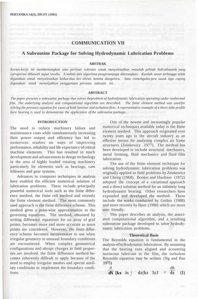
Fig, 1; Bearing geometry and nomenclature for the numerical model
360 PERTANIKAVOL. 14NO.3, 1991
A SUBROUTINE PACKAGE FOR SOLVING HYDRODYNAMIC LUBRICATION PROBLEMS
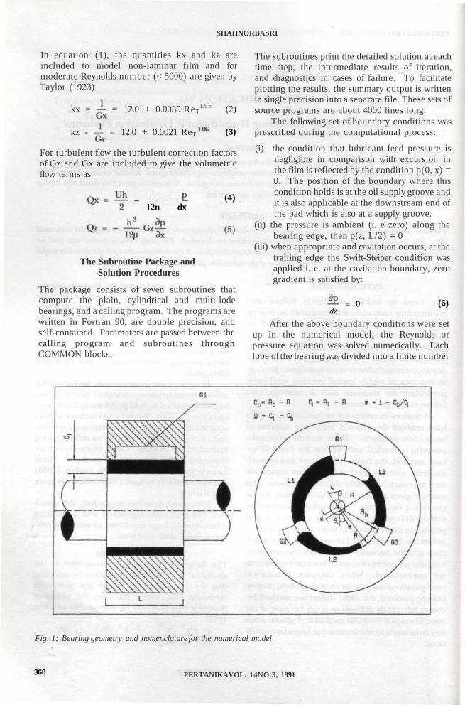
of eight noded isoparametric elements of theserendipity family as shown in Figure 2 andthroughout this study a mesh comprising 80elements was used. Four elements were used in thehalf bearing length with twenty elements beingemployed in the direction of shaft rotation. Thefine circumferential division was necessary to en-able accurate calculation of the Swift-Steiberboundary condition.
The solutions for pressure distribution in thelubricant flow were obtained using an iterativescheme and the strategic steps in the solutionprocedure were the following:
(i) Define bearing geometry R, R ,̂ m, U, 9 and G
and assume an initial bearing attitude angle (p.(ii) Set-up initial pressure boundary conditions
and the finite element mesh.(iii) Calculate film thickness in each lobe of the
bearing.(iv) Solve the Reynolds or pressure equation.(v) Continue the iteration for the pressure
generation within the clearance gap of thebearing (i. e. steps iii and iv) until theagreement between two successive iterationsat all points within the finite element mesh isbetter than 0.5%.
(vi) When step v has converged, by appropriateintegration, the parameters which are of
Fig, 2: The finite element, mesh and associated boundary conditions
PERTANIKAVOL. 14NO.3,1991 361
SHAHNORBASRI
interest to the bearing designer (load carryingcapacity, power loss and side leakage) arecalculated by a simple summation over thebearing lobes.
The computer program developed for theturbulent calculation allows the assumption ofeither laminar, transition or turbulent flow withinthe gap depending on the magnitude of the localfilm Reynolds number. The change of flow type iscarried out automatically in the course of theiteration process, whenever the local film Reynoldsnumber value falls in the limit defined by thefollowing bands (Frene and Constantinescu 1975)
Ref < Reel and ReT = 0 (Laminar) (7)
Ref > Rec2 and Ref • ReT (Turbulent) (8)
andRef -ReelReel < Ref < Rec2 and ReT = ^-±—~-
z—-RefT Rec2-Recl (
(Transition)
where
.(9)
Reel = 41.2 —1/2
(10)
while the establishment of fully turbulent flow thefilm Reynolds number is at twice Reel, i. e.
Rec2 = 2Recl (11)
€
0.1000.3100.4290.7020.8060.882
1
111122
TABLE 1Global performance data
1
1.,2340.3530.0.0.
181.085.054
0.034
H
.424
.478
.574
.794
.016
.290
2
1,11.12,2,
S
,432479.577,796,208.293
2
1.2340.3550.1820.0860.0550.036
Ql
0.1340.1470.1650.1890.2070.232
1
60.0961.0059.4655.2351.6847.19
2
0.1350.1470.1680.1910.2090.231
2
60.2461.2060.0255.7051.9247.19
1-data from Lund and Thomsen 1978 2-present data
Sample Computation and DiscussionFrom a design viewpoint, performance trends areessential to enable bearing selection for a particularengineering application. Therefore in this section,steady state design characteristics of a three-lobeprofile bore bearing are presented.
Verification of the Numerical ModelsBefore proceeding with the parametric study, toconfirm the basis of the mathematical model usedin this paper, the computed global performancedata for the basic bearing were compared withpublished data from Lund and Thomsen 1978 andFlack and Allaire 1982 and are presented in Table1 and Figure 3.
It can be seen clearly that the baseline modeldeveloped (Table 1) shows complete agreementwith published data which confirms its foundationwith regards to this work.
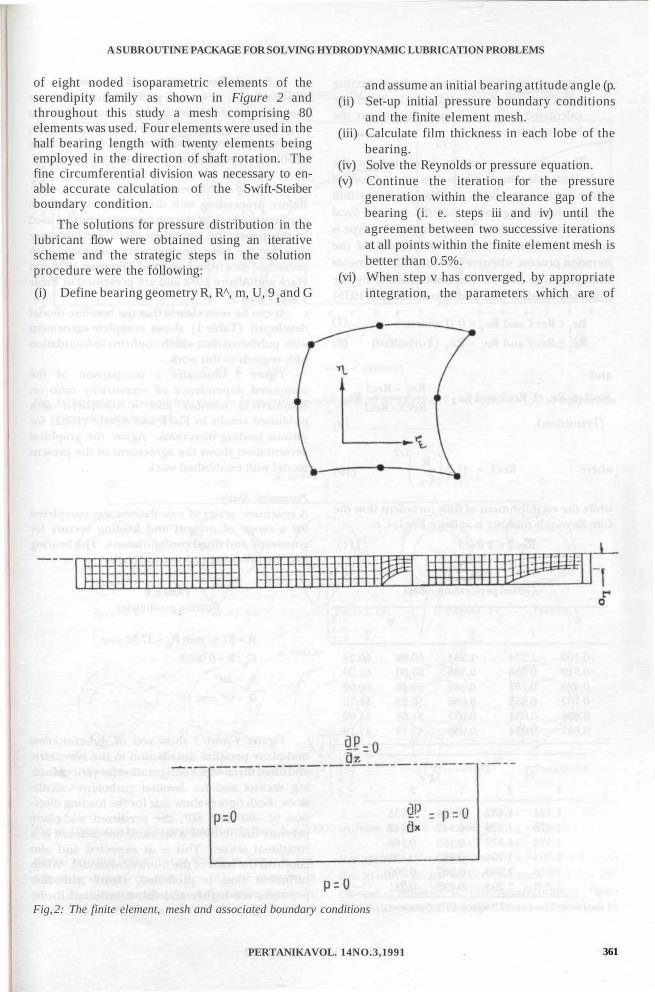
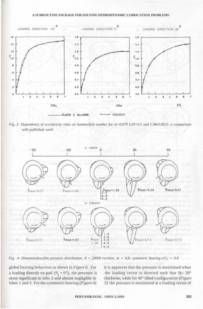
Figure 3 illustrates a comparison of thecomputed dependence of eccentricity ratio onSommerfeld number and is compared withpublished results by Flack and Allaire (1982) forvarious loading directions. Again, the graphicalpresentation shows the agreement of the presentmodel with established work.
Parametric StudyA systematic series of calculations was completedfor a range of present and loading vectors forsymmetric and tilted configurations. The bearinghad the following geometric details:
TABLE 2Bearing geometries
R = 37.41 mm 1^ = 37.52 mm
Cb/R = 0.0003
6 =20°
6 = O° and 40°
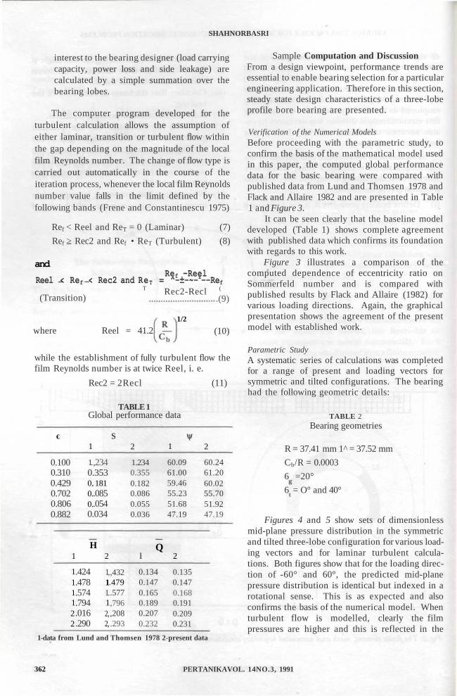
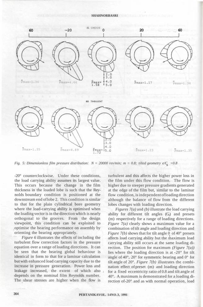
Figures 4 and 5 show sets of dimensionlessmid-plane pressure distribution in the symmetricand tilted three-lobe configuration for various load-ing vectors and for laminar turbulent calcula-tions. Both figures show that for the loading direc-tion of -60° and 60°, the predicted mid-planepressure distribution is identical but indexed in arotational sense. This is as expected and alsoconfirms the basis of the numerical model. Whenturbulent flow is modelled, clearly the filmpressures are higher and this is reflected in the
362 PERTANIKAVOL. 14NO.3, 1991
A SUBROUTINE PACKAGE FOR SOLVING HYDRODYNAMIC LUBRICATION PROBLEMS
LOADING DIRECTION -30 LOADING DIRECTION 0 LOADING DIRECTION 30
1/SO
FLACK £ ALLAIRE
I/So
PRESENT
1/S,
Fig. 3: Dependence of eccentricity ratio on Sommerfeld number for m=0.879 L/D=0.5 and CJR-0.0015: a comparison
with published work
Pmax=0.57
Pmax=0.73
-20U) LAMINAR
Pmax=i.06
(3) TURBULENT
\ v
?max=l.07 Pmax=1 .68
20
Pmax=4.24 Pmax=0.67
rPmax=4.7 3 Pmax=0.7 3
Fig. 4: Dimensionless film pressure distribution: N = 20000 rev/min; m = 0,8; symmetric bearing e/Cb = 0.8
global bearing behaviour as shown in Figure 6. For it is apparent that the pressure is maximised whena loading directly on-pad (9 • 0°), the pressure is the loading vector is directed such that 9j= 20°more significant in lobe 2 and almost negligible in clockwise, while for 40° tilted configuration (Figurelobes 1 and 3. For the symmetric bearing (Figure 4) 5) the pressure is maximised at a loading vector of
PERTANIKAVOL. 14NO.3,1991 363
SHAHNORBASRI
60(Al UMDUH
-20 0 20 60
Pmax=l.34 Pmax=4.66 Pmax=1.17 Pmax=i.34
£BJ TIHBULENT
Pmax=l.35 Pmax=4.89 Pmax=l.23 Pmax=l.35
Fig. 5: Dimensionless film pressure distribution: N = 20000 rev/min; m = 0.8; tilted geometry e/C =0.8
-20° counterclockwise. Under these conditions,the load carrying ability assumes its largest value.This occurs because the change in the filmthickness in the loaded lobe is such that the Rey-nolds boundary condition is positioned at thedownstream end of lobe 2. This condition is similarto that for the plain cylindrical bore geometrywhere the load-carrying ability is optimised whenthe loading vector is in the direction which is nearlyorthogonal to the grooves. From the designviewpoint, this condition can be exploited tooptimise the bearing performance on assembly byorienting the bearing appropriately.
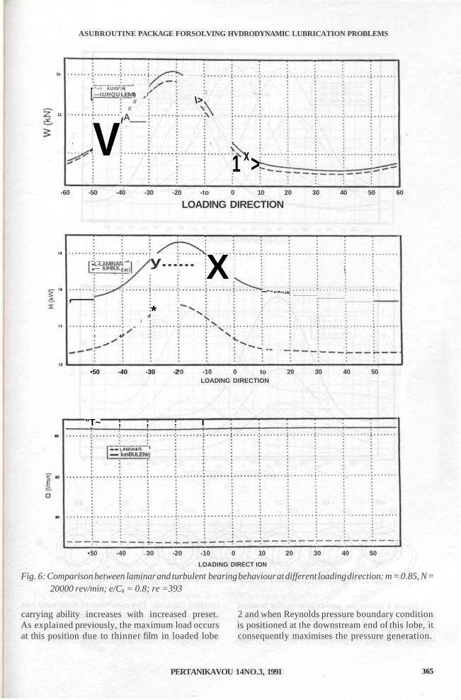
Figure 6 illustrates the effects of including theturbulent flow correction factors in the pressureequation over a range of loading directions. It canbe seen that the bearing global behaviour isidentical in form to that for a laminar calculationbut with enhanced load carrying capacity due to theincrease in pressure generation. Power loss andleakage increased, the extent of which alsodepends on the nominal film Reynolds number.The shear stresses are higher when the flow is
turbulent and this affects the higher power loss inthe film under this flow condition. The flow ishigher due to steeper pressure gradients generatedat the edge of the film but, similar to the laminarflow condition, is independent of loading directionalthough the balance of flow from the differentlobes changes with loading direction.
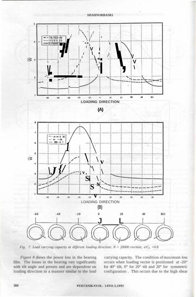
Figures 7(a) and (b) illustrate the load carryingability for different tilt angles (Gt) and presets(m) respectively for a range of loading directions.Figure 7(a) clearly shows a maximum value for acombination of tilt angle and loading direction andFigure 7(b) shows that for tilt angle 0 of 40° presetsaffects load carrying ability but the maximum loadcarrying ability still occurs at the same loading di-rection. The position for maximum (Figure 7(a))lies where the loading direction is at -20° for tiltangle of 40°, 20° for symmetric bearing and 0° fortilt angle of 20°. Figure 7(b) illustrates the combi-nation effect of preset (m) and loading directionfor a fixed eccentricity ratio of 0.8 and tilt angle of40°. A maximum is demonstrated for a loading di-rection of-20° and as with normal operation, load
364 PERTANIKAVOL. 14NO.3, 1991
ASUBROUTINE PACKAGE FORSOLVING HVDRODYNAMIC LUBRICATION PROBLEMS
70
11
[ ^ • i AUIN*—tUHQU
VLEMl) /
////
.A/
\>V
\
1 x>-60 -50 -40 -30 -20 -to 0 10 20 30 40 50 60
LOADING DIRECTION
,
L-LAMINAF— IUH8UL
! 4
/
y......
*
•50 -40 -30 -2
X*** ' • " 'JM
L -1 — .
1 — ;
,
,
0 -10 0 to 20 30 40 50LOADING DIRECTION
"T~ ; ; : I
lunBULENrj ;
• 50 -40 30 -20 -10 0 10 20 30 40 50
LOADING DIRECT ION
Fig. 6: Comparison between laminar and turbulent bearing behaviour at different loading direction: m = 0.85, N =20000 rev/min; e/Ck = 0.8; re =393
carrying ability increases with increased preset. 2 and when Reynolds pressure boundary conditionAs explained previously, the maximum load occurs is positioned at the downstream end of this lobe, itat this position due to thinner film in loaded lobe consequently maximises the pressure generation.
PERTANIKAVOU 14NO.3, 1991 365
SHAHNORBASR1
A
3
2
• •i
—'
• TILTED 40- I I U E 0 20•SYMMETRIC
•
v: —— -
/: //§
j
/
if
/
^———
• >/
//
7
/ :/ :
/
V i\ •
\ «\ .Vv •\
/
\
)/
i\\, V
V\
v
-50 -40 -30 •20 -10 0 10 20
LOADING DIRECTION40 SO
(A)
* • - m m— in •— m-
\J
0 8S080 7
1\
{/\
V
; v ,Si
\
\\
\S N
v
v\
-60 -40 -30 -20 -10 0 10 20 30 40 50
LOADING DIRECTION
(B)-60 -40 -20 0 20 40 BO
J L
Fig. 7: Load carrying capacity at different loading direction: N = 20000 rev/min; e/Cb =0.8
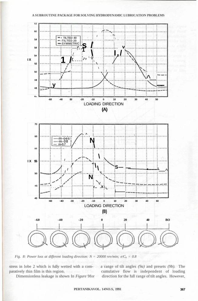
Figure 8 shows the power loss in the bearing carrying capacity. The condition of maximum lossfilm. The losses in the bearing vary significantly occurs when loading vector is positioned at -20°with tilt angle and presets and are dependent on for 40° tilt, 0° for 20° tilt and 20° for symmetricloading direction in a manner similar to the load configuration . This occurs due to the high shear
366 PERTANIKAVOL. 14NO.3,1991
A SUBROUTINE PACKAGE FOR SOLVING HYDRODYNAMIC LUBRICATION PROBLEMS
I X52
.
y
• TILTED 40-TILTED 20-SYMMETRIC
1 /
f
y*.: / * *
/
r• * • • / •
s /1 \
y V* . /...A
/
/
i
\
\
>
/
i
\
vI , /
^—-
-60 -40 00 -20 -10 0 10 20 30 40 50
LOADING DIRECTION(A)
60
I X S5
—-m-oes—-m-08 I— m-0.7 |
-
k >
/
/ //
/
J€
y
- ^ :
N
<l
N
\
\\ \
V>5^
Vr... .X L-
S—
i
— •————1 ^
40•60 ~4O -30 -20 -10 0 10 20 30 40 60
LOADING DIRECTION
(B)
-60 -40 -20 0 20 40 BO
Fig. 8: Power loss at different loading direction: N = 20000 rev/min; e/Cb = 0.8
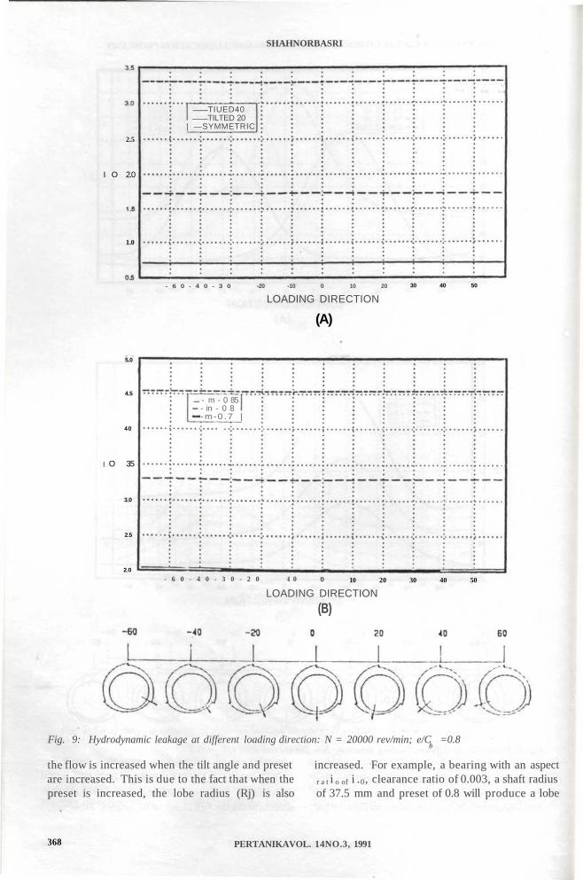
stress in lobe 2 which is fully wetted with a com- a range of tilt angles (9a) and presets (9b). Theparatively thin film is this region. cumulative flow is independent of loading
Dimensionless leakage is shown In Figure 9for direction for the full range of tilt angles. However,
PERTANIKAVOL. 14NO.S, 1991 367
SHAHNORBASRI
2.5
I O 2.0
1.0
TIUED40TILTED 20
| —SYMMETRIC
- 6 0 - 4 0 - 3 0 -20 -10 0 10 20
LOADING DIRECTION30 40 50
(A)
5.0
4.5
40
O 35
3.0
2.5
2.0
— - m - 0 85- in - 0 8-m-0 .7 |
- 6 0 - 4 0 - 3 0 - 2 0 1 0 10 20 30 40 50
LOADING DIRECTION
(B)
Fig. 9: Hydrodynamic leakage at different loading direction: N = 20000 rev/min; e/C =0.8
the flow is increased when the tilt angle and preset increased. For example, a bearing with an aspectare increased. This is due to the fact that when the r a t i o of i .0, clearance ratio of 0.003, a shaft radiuspreset is increased, the lobe radius (Rj) is also of 37.5 mm and preset of 0.8 will produce a lobe
368 PERTANIKAVOL. 14NO.3, 1991
A SUBROUTINE PACKAGE FOR SOLVING HYDRODYNAMIC LUBRICATION PROBLEMS
radius equal to 38 mm; and a bearing with a presetof 0.7 will have a lobe radius of 37.78 mm. Thisshows that lobe clearance (C}) is proportional tothe bearing preset and therefore as the presetincreases, the flow increases too. For this reason,the load-carrying capacity at high presets decreases,leading to improvement in heat removal char-acteristics.
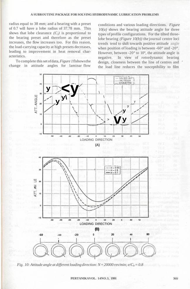
To complete this set of data, Figure 1 flshows thechange in attitude angles for laminar flow
conditions and various loading directions. Figure10(a) shows the bearing attitude angle for threetypes of profile configurations. For the tilted three-lobe bearing (Figure 10(b)) the journal centre locitrends tend to shift towards positive attitude anglewhen position of loading is between -60° and -20°.However, between -20° to 10°, the attitude angle isnegative. In view of rotordynamic bearingdesign, closeness between the line of centres andthe load line reduces the susceptibility to film
ys
y<yy\
i*
i
%
N
/
\
\
\
\
>
\
\
V"\\\
\
\\
\
>
— 1IU ED AtT^iHLTE020
— SYMMETRIC 1
vy
y
y
y~*
LOADING DIRECTION
(A)
<
-60
-50 -40 -00 -20 -10 0 10 20 X 40 'O
LOADING DIRECTION
(B)- 40
I
-20 20 40
I80
Fig. 10: Attitude angle at different loading direction: N = 20000 rev/min; e/Cb = 0.8
PERTANIKAVOL. 14NO.3, 1991
SHAHNORBASRI
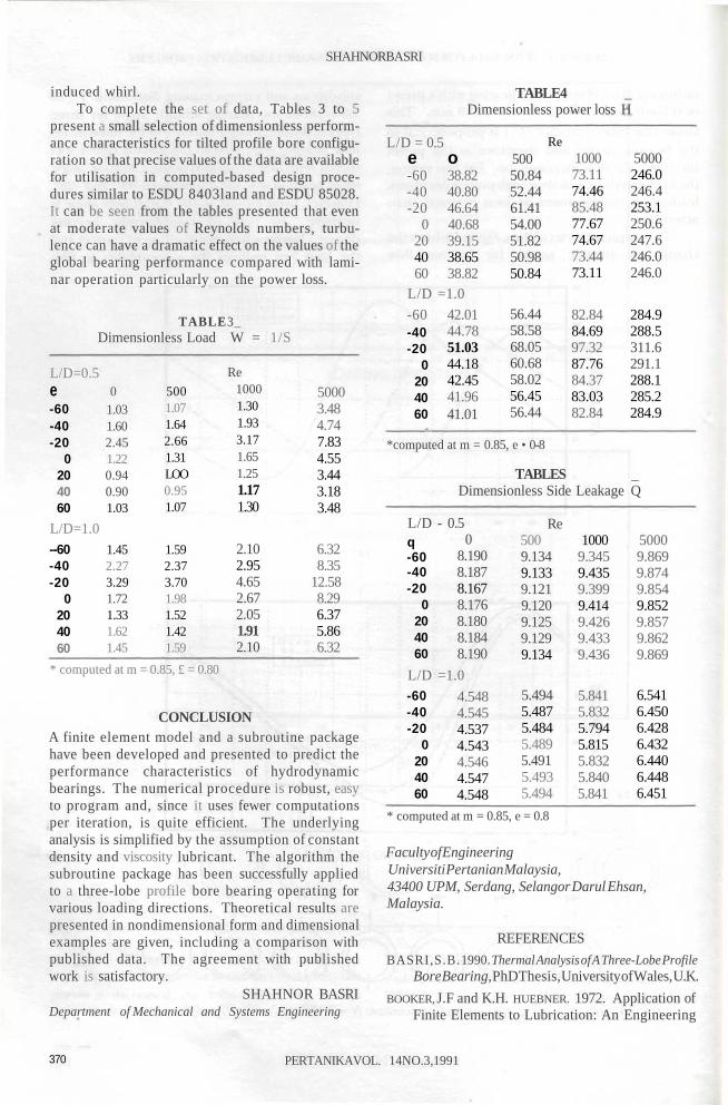
induced whirl.To complete the set of data, Tables 3 to 5
present a small selection of dimensionless perform-ance characteristics for tilted profile bore configu-ration so that precise values of the data are availablefor utilisation in computed-based design proce-dures similar to ESDU 8403land and ESDU 85028.It can be seen from the tables presented that evenat moderate values of Reynolds numbers, turbu-lence can have a dramatic effect on the values of theglobal bearing performance compared with lami-nar operation particularly on the power loss.
TABLE3_Dimensionless Load W = 1/S
TABLE4 _Dimensionless power loss H
L/D=0.5e-60-40-20
0204060
L/D=1.0--60-40-20
0204060
01.031.602.451.220.940.901.03
1.452.273.291.721.331.621.45
5001.071.642.661.31LOO0.951.07
1.592.373.701.981.521.421.59
Re10001.301.933.171.651.251.171.30
2.102.954.652.672.051.912.10
50003.484.747.834.553.443.183.48
6.328.35
12.588.296.375.866.32
* computed at m = 0.85, £ = 0.80
CONCLUSIONA finite element model and a subroutine packagehave been developed and presented to predict theperformance characteristics of hydrodynamicbearings. The numerical procedure is robust, easyto program and, since it uses fewer computationsper iteration, is quite efficient. The underlyinganalysis is simplified by the assumption of constantdensity and viscosity lubricant. The algorithm thesubroutine package has been successfully appliedto a three-lobe profile bore bearing operating forvarious loading directions. Theoretical results arepresented in nondimensional form and dimensionalexamples are given, including a comparison withpublished data. The agreement with publishedwork is satisfactory.
SHAHNOR BASRIDepartment of Mechanical and Systems Engineering
L/D = 0.5e o-60 38.82-40 40.80-20 46.64
0 40.6820 39.1540 38.6560 38.82
L/D =1.0
-60 42.0144.7851.0344.1842.4541.96
Re
-40-20
0204060 41.01
50050.8452.4461.4154.0051.8250.9850.84
56.4458.5868.0560.6858.0256.4556.44
100073.1174.4685.4877.6774.6773.4473.11
82.8484.6997.3287.7684.3783.0382.84
5000246.0246.4253.1250.6247.6246.0246.0
284.9288.5311.6291.1288.1285.2284.9
*computed at m = 0.85, e • 0-8
TABLES _Dimensionless Side Leakage Q
L/D - 0.50
8.190q-60-40-20
0204060
8.1878.1678.1768.1808.1848.190
L/D =1.0-60-40-20
0204060
4.5484.5454.5374.5434.5464.5474.548
Re5009.1349.1339.1219.1209.1259.1299.134
5.4945.4875.4845.4895.4915.4935.494
10009.3459.4359.3999.4149.4269.4339.436
5.8415.8325.7945.8155.8325.8405.841
50009.8699.8749.8549.8529.8579.8629.869
6.5416.4506.4286.4326.4406.4486.451
* computed at m = 0.85, e = 0.8
Faculty of EngineeringUniversiti Pertanian Malaysia,43400 UPM, Serdang, Selangor Darul Ehsan,Malaysia.
REFERENCES
BASRI,S.B. 1990. Thermal Analysis of A Three-Lobe ProfileBore Bearing, PhDThesis, University of Wales, U.K.
BOOKER, J.F and K.H. HUEBNER. 1972. Application ofFinite Elements to Lubrication: An Engineering
370 PERTANIKAVOL. 14NO.3,1991
A SUBROUTINE PACKAGE FOR SOLVING HYDRODYNAMIC LUBRICATION PROBLEMS
Approach. Trans ASME (JOLT) 24(4): 313-323.
FLACK, R. D. and P.E. ALLAIRE. 1982. An Experimental
and Theoretical Examination of the StaticCharacteristics of Three Lobe Bearings. Trans.ASLE 25(1): 88-91.
FRENEj.andV.N. CONSTANTINESCU. 1975. Operating
Characteristics of Journal Bearings in TransitionRegime. In Proceedings of Leeds-Lyon Symposium onTribology, eds. Dowson, Godet and Taylor.
GETHIN, D.T. 1988. Finite Element Approach toAnalysing Thermohydrodynamic Lubrication inJournal Bearings. Tn'fology International 21(2): 67-75.
LUND, J.W. and K.K. THOMSEN. 1978. A Calculation
Method and Data for Dynamic Coefficients of Oil-Lubricated Journal Bearings, Special Publication ofthe American Society of Mechanical Engineers,No. 100118, New York.
NG.CW.andC.H.T.PAN. 1975. A Linearized TurbulentLubrication Theory Trans. ASME Journal of BasicEngineering 87: 264-269.
TAYLOR, G.I. 1923. Stability of a Viscous LiquidContained between Two Rotating Cylinders, Phil.Trans. Roy, Soc. London, 223(A): 289-343.
ZEINKEWICZ, O.C. 1977. The Finite Element Method, 3rdEdition, McGraw-Hill Publication.
ZEINKEWICZ, O.C. and YK. CHENG. 1968. Finite
Elements in the Solution of Field Problems. TheEngineers 24: 507-510.
(Received 2 May, 1991)
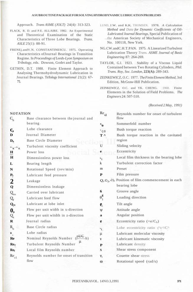
NOTATION
c,D
Db
G x' G zH
H
L
N
Pf
2Q
Q.n
0,
R
R .Re
ReT
Ref
Base clearance between the journal andbearing
Lobe clearance
Journal Diameter
Base Circle Diameter
Turbulent viscosity coefficient
Power loss
Dimensionless power loss
Bearing length
Rotational Speed (rev/min)
Lubricant feed pressure
Leakage
Dimensionless leakage
Carried over lubricant
Lubricant feed flow
Lubricant at lobe inlet
Flow per unit width in x-direction
Flow per unit witdth in z-direction
Journal radius
Base Circle radius
Lobe radiusoUC
Nominal Reynolds Number (i- b)
Turbulent Reynolds Number
Local film Reynolds number
Reynolds number for onset of transition
flow
c2
SoT Q B
T ^
U
e
h ik
m
P
Qv ©2, <
6g
e
a
e
e i
V
PX
Tc
CO
Reynolds number for onset of turbulentflow
Sommerfeld number
Bush torque reaction
Bush torque reaction in the cavitated
region
Sliding velocity
Eccentricity
Local film thickness in the bearing lobe
Turbulent correction factor
Preset
Film pressure
•)3 Position of film commencement in each
bearing lobe
Groove angle
Loading direction
Tilt angle
Attitude angle
Angular position
Eccentricity ratio (=e/Cb)
Lobe eccentricity ratio (^c^/C^
Lubricant molecular viscosity
Lubricant kinematic viscosity
Lubricant density
Shear stress component
Couette shear stress
Rotational speed (rad/s)
PERTANIKAVOL. 14NO.3,1991 371