combustion characteristics of methane in a direct injection engine
TRANSCRIPT
Jurnal Kejuruteraan 22(2010): 43-52
Combustion Characteristics of Methane in A Direct Injection Engine UsingSpark Plug Fuel Injector
(Ciri Pembekaran Metana dalam Enjin Suntikan Terus Menggunakan Palam Pencucuh Penyuntik Bahan Api (SPFI))
Taib Iskandar Mohamad
ABSTRACT
The combustion characteristics of methane in a direct injection spark ignition engine using Spark Plug Fuel Injector (SPFI) was investigated. SPFI is a system developed to convert any externally-mixing (port injection, carburetor) spark ignition engine to direct injection by combining fuel injectors into spark plugs. The burning rates of methane were measured using normalized combustion pressure method, where the normalized pressure rise due to combustion is equivalent to the mass fraction burnt at the specific crank angle. A single cylinder research engine was installed with the SPFI system. Cylinder pressures were taken with engine running at 1100 rpm and stoichiometric air/fuel ratio. The spark timing was set at 25oBTDC. For comparison, the engine was run with methane port injection. The optimal fuel injection timing with SPFI was found to be 170o BTDC. Results showed that SPFI direct injection, increased the volumetric efficiency by 11% compared to port injection, resulting in higher heating value of cylinder charge per cycle. Combustion analysis show that the overall burning rate of methane direct injection is faster than the ones of port injection although is slower at the initial stage. Injection pressures affect ignition delay but not the combustion duration. Changing mixture stoichiometry affects the magnitude of ignition delay. Combustion duration increases with leaner mixture. Different load conditions have significant effect on combustion process. Lower loads tend to increase combustion duration but shorten ignition delay. SPFI Di methane system has the potential of increasing engine performance due to increased volumetric efficiency and faster burning rate.
Keywords: Burning rate; methane; direct injection; spark plug fuel injector; combustion
ABSTRAK
Ciri pembakaran metana dalam enjin suntikan terus menggunakan palam pencucuh penyuntik bahan api (SPFI) telah dikaji. Sistem SPFI dibangunkan untuk menukar sistem bahan api karburetor dan suntikan liang enjin cucuhan bunga api kepada sistem suntikan terus dengan menggabungkan palam pencucuh dan penyuntik bahan api dalam satu struktur. Kadar pembakaran metana diukur berdasarkan kaedah tekanan pembakaran ternormal, iaitu peningkatan tekanan ternormal berkadar terus dengan nisbah jisim terbakar pada sesuatu sudut engkol. Sebuah enjin penyelidikan satu silinder dilengkapkan dengan sistem SPFI. Tekanan dalam silinder diukur semasa enjin beroperasi pada halaju 1100 putaran se-minit dan campuran udara-metana stoikiometri. Masa pencucuhan disetkan pada 250 sebelum titik mati atas. Sebagai perbandingan, enjin ini juga diuji dengan sistem bahan api suntikan liang. Bagi sistem SPFI, prestasi enjin optimum dicapai pada masa suntikan 170o sebelum titik mati atas. Operasi SPFI telah meningkatkan kecekapan isipadu sebanyak 11% berbanding operasi suntikan liang. Ini menyebabkan peningkatan nilai haba bagi caj silinder pada setiap kitaran. Analisis pembakaran menunjukkan tempoh pembakaran metana dengan operasi SPFI lebih laju berbanding suntikan liang, walaupun kadar pembakaran permulaan yang lebih perlahan. Tekanan suntikan yang berbeza memberi kesan terhadap lengah pencucuhan tetapi tidak terhadap tempoh pembakaran. Stoikiometri campuran memberi kesan terhadap lengah pencucuhan. Tempoh pembakaran semakin panjang pada campuran kurang. Pembakaran juga amat terkesan dengan keadaan bebanan. Bebanan rendah meningkatkan tempoh pembakaran tetapi mengurangkan lengah pencucuhan. Sistem SPFI berpotensi meningkatkan prestasi enjin kerana penambahan kecekapan isipadu dan kadar pembakaran metana yang lebih cepat.
Kata kunci: Kadar pembakaran; metana; suntikan terus; palam pencucuh penyuntik bahanapi; pembakaran
INTRODUCTION
Increasing concerns over pollutant emission and depleting fossil fuel reserve has geared search for alternative to automotive conventional fuels. Natural gas has been one of the highly considered alternative fuels for both spark ignition
and compression ignition engines for its cleaner emission, relatively lower price and characteristically adaptable to those engine operations (How et al. 2009). However, the use of natural gas in externally air-fuel mixing spark ignition engines, i.e. carburetor or port injection, results in reduced
44
power and limited engine upper speed. These are the results of reduced volumetric efficiency due to displaced air in the intake manifold and lower burning velocity respectively (Jermy 2004 & Mohamad 2003). To mitigate the problem, natural gas is injected directly into the combustion chamber after the intake valve has closed. This will improve volumetric efficiency, thus increasing absolute heating value of air-fuel mixture (Mohamad 2010). Stratified charge combustion, which is one of the most effective means of improving the thermal efficiency of current internal combustion engines can be achieved by direct fuel injection. Direct injection natural gas has the potential of achieving the specific fuel consumption equivalent to those of diesel engines over a broad range of load, speed and output power (Goto 1999; Huang 2003 & Zeng 2006). Moreover, the combustion from direct injection is faster than those of carburetion and port injection, which is advantageous (Hassaneen et al. 1998). This paper presents results of investigations on methane (main constituent of natural gas) burning rate of a newly developed natural gas/methane direct injection using spark plug fuel injector (SPFI) for low cost conversion from port injection or carburetion to direct injection. SPFI is a device that combines a spark plug with fuel injector without modification to the spark plug attachment to the engine. Therefore, any port injection or carburetion spark ignition engine can be converted to direct injection without any modification to the engine’s original structure. In the experiments, methane was used as natural gas substitute.
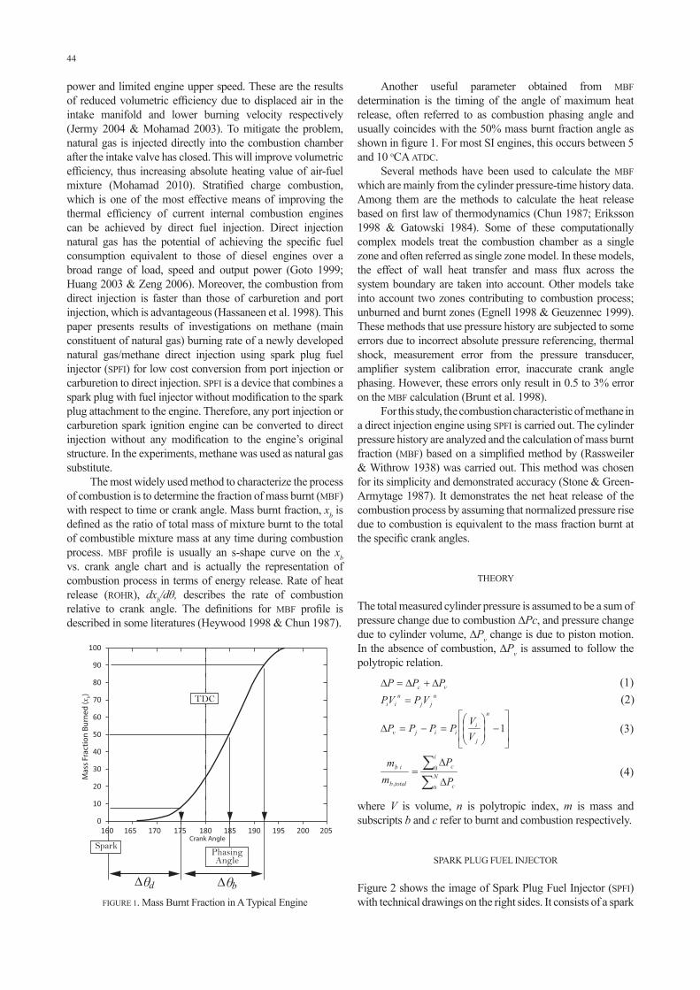
The most widely used method to characterize the process of combustion is to determine the fraction of mass burnt (MBF) with respect to time or crank angle. Mass burnt fraction, xb is defined as the ratio of total mass of mixture burnt to the total of combustible mixture mass at any time during combustion process. MBF profile is usually an s-shape curve on the xb vs. crank angle chart and is actually the representation of combustion process in terms of energy release. Rate of heat release (ROHR), dxb/dθ, describes the rate of combustion relative to crank angle. The definitions for MBF profile is described in some literatures (Heywood 1998 & Chun 1987).
Another useful parameter obtained from MBF determination is the timing of the angle of maximum heat release, often referred to as combustion phasing angle and usually coincides with the 50% mass burnt fraction angle as shown in figure 1. For most SI engines, this occurs between 5 and 10 oCA ATDC.
Several methods have been used to calculate the MBF which are mainly from the cylinder pressure-time history data. Among them are the methods to calculate the heat release based on first law of thermodynamics (Chun 1987; Eriksson 1998 & Gatowski 1984). Some of these computationally complex models treat the combustion chamber as a single zone and often referred as single zone model. In these models, the effect of wall heat transfer and mass flux across the system boundary are taken into account. Other models take into account two zones contributing to combustion process; unburned and burnt zones (Egnell 1998 & Geuzennec 1999). These methods that use pressure history are subjected to some errors due to incorrect absolute pressure referencing, thermal shock, measurement error from the pressure transducer, amplifier system calibration error, inaccurate crank angle phasing. However, these errors only result in 0.5 to 3% error on the MBF calculation (Brunt et al. 1998).
For this study, the combustion characteristic of methane in a direct injection engine using SPFI is carried out. The cylinder pressure history are analyzed and the calculation of mass burnt fraction (MBF) based on a simplified method by (Rassweiler & Withrow 1938) was carried out. This method was chosen for its simplicity and demonstrated accuracy (Stone & Green-Armytage 1987). It demonstrates the net heat release of the combustion process by assuming that normalized pressure rise due to combustion is equivalent to the mass fraction burnt at the specific crank angles.
THEORY
The total measured cylinder pressure is assumed to be a sum of pressure change due to combustion ∆Pc, and pressure change due to cylinder volume, ∆Pv change is due to piston motion. In the absence of combustion, ∆Pv is assumed to follow the polytropic relation.
where V is volume, n is polytropic index, m is mass and subscripts b and c refer to burnt and combustion respectively.
SPARK PLUG FUEL INJECTOR
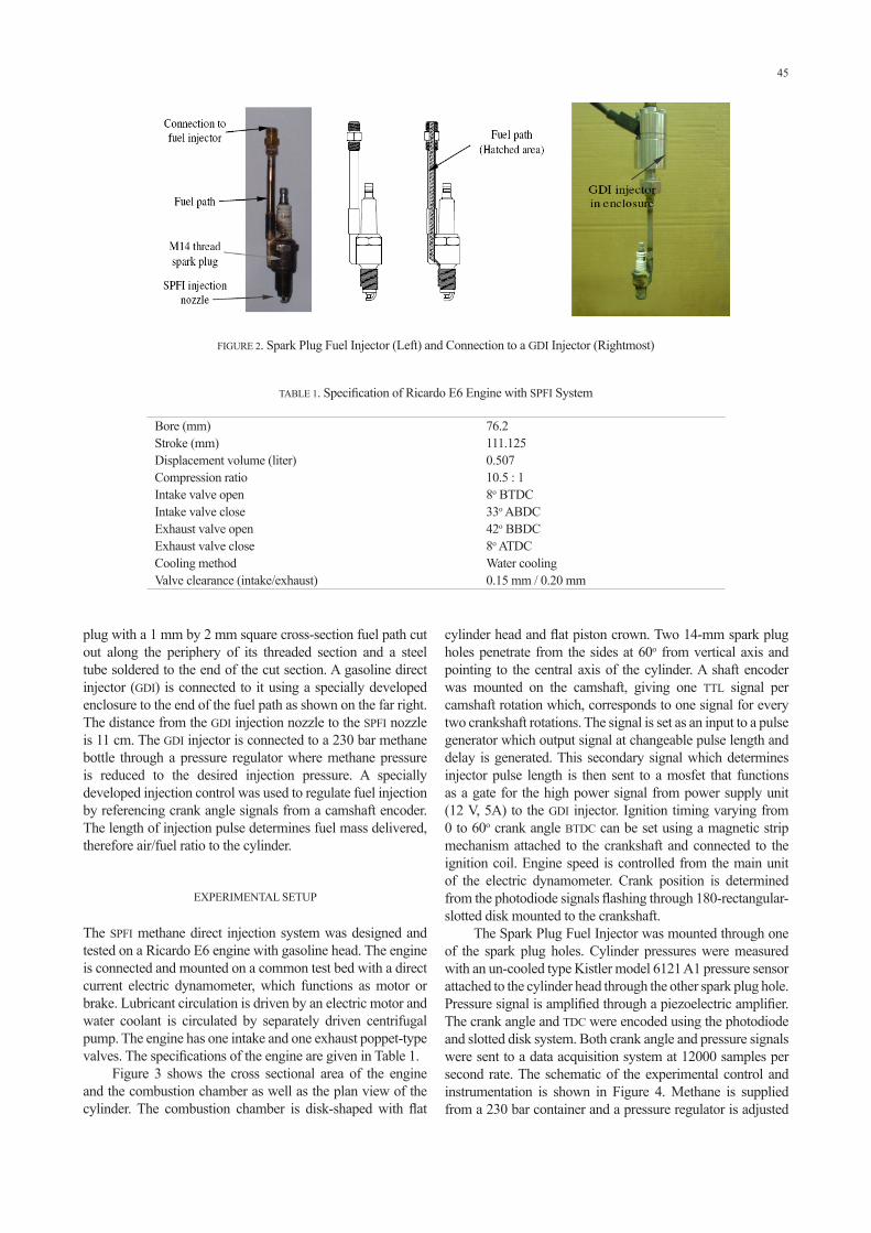
Figure 2 shows the image of Spark Plug Fuel Injector (SPFI) with technical drawings on the right sides. It consists of a spark FIGURE 1. Mass Burnt Fraction in A Typical Engine
45
plug with a 1 mm by 2 mm square cross-section fuel path cut out along the periphery of its threaded section and a steel tube soldered to the end of the cut section. A gasoline direct injector (GDI) is connected to it using a specially developed enclosure to the end of the fuel path as shown on the far right. The distance from the GDI injection nozzle to the SPFI nozzle is 11 cm. The GDI injector is connected to a 230 bar methane bottle through a pressure regulator where methane pressure is reduced to the desired injection pressure. A specially developed injection control was used to regulate fuel injection by referencing crank angle signals from a camshaft encoder. The length of injection pulse determines fuel mass delivered, therefore air/fuel ratio to the cylinder.
EXPERIMENTAL SETUP
The SPFI methane direct injection system was designed and tested on a Ricardo E6 engine with gasoline head. The engine is connected and mounted on a common test bed with a direct current electric dynamometer, which functions as motor or brake. Lubricant circulation is driven by an electric motor and water coolant is circulated by separately driven centrifugal pump. The engine has one intake and one exhaust poppet-type valves. The specifications of the engine are given in Table 1.
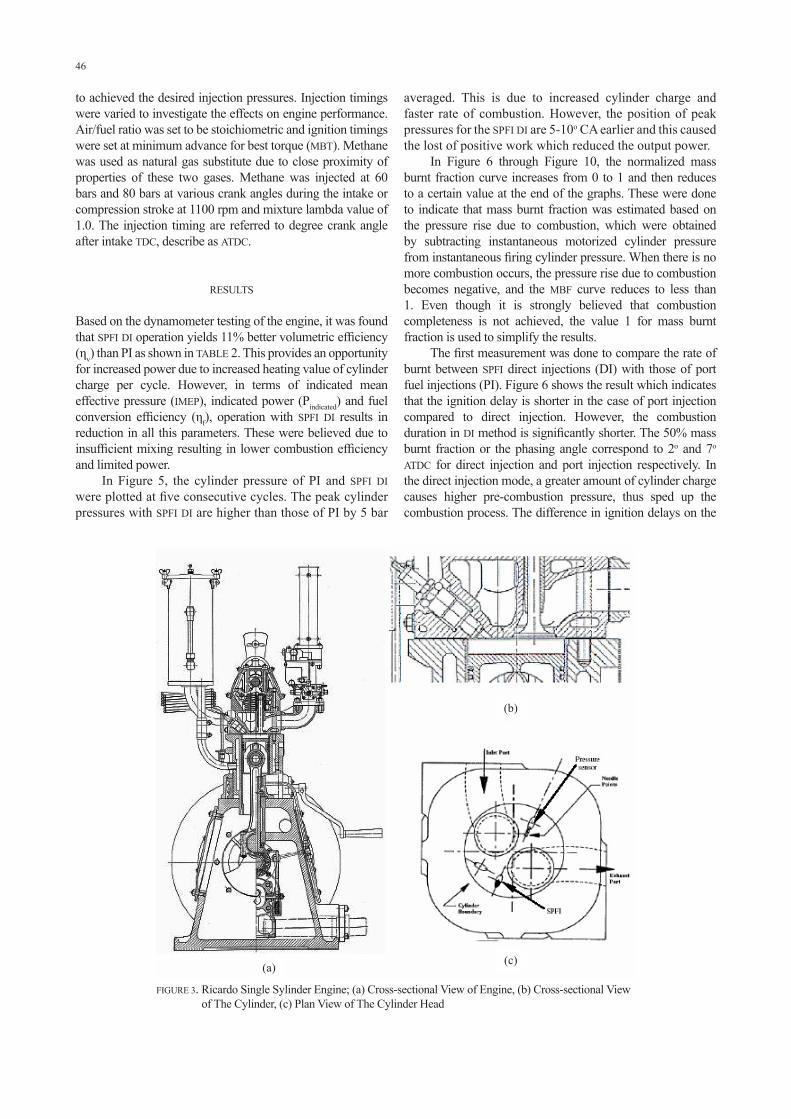
Figure 3 shows the cross sectional area of the engine and the combustion chamber as well as the plan view of the cylinder. The combustion chamber is disk-shaped with flat
FIGURE 2. Spark Plug Fuel Injector (Left) and Connection to a GDI Injector (Rightmost)
TABLE 1. Specification of Ricardo E6 Engine with SPFI System
Bore (mm) 76.2Stroke (mm) 111.125Displacement volume (liter) 0.507Compression ratio 10.5 : 1Intake valve open 8o BTDCIntake valve close 33o ABDCExhaust valve open 42o BBDCExhaust valve close 8o ATDCCooling method Water coolingValve clearance (intake/exhaust) 0.15 mm / 0.20 mm
cylinder head and flat piston crown. Two 14-mm spark plug holes penetrate from the sides at 60o from vertical axis and pointing to the central axis of the cylinder. A shaft encoder was mounted on the camshaft, giving one TTL signal per camshaft rotation which, corresponds to one signal for every two crankshaft rotations. The signal is set as an input to a pulse generator which output signal at changeable pulse length and delay is generated. This secondary signal which determines injector pulse length is then sent to a mosfet that functions as a gate for the high power signal from power supply unit (12 V, 5A) to the GDI injector. Ignition timing varying from 0 to 60o crank angle BTDC can be set using a magnetic strip mechanism attached to the crankshaft and connected to the ignition coil. Engine speed is controlled from the main unit of the electric dynamometer. Crank position is determined from the photodiode signals flashing through 180-rectangular-slotted disk mounted to the crankshaft.
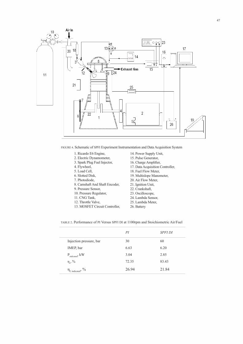
The Spark Plug Fuel Injector was mounted through one of the spark plug holes. Cylinder pressures were measured with an un-cooled type Kistler model 6121 A1 pressure sensor attached to the cylinder head through the other spark plug hole. Pressure signal is amplified through a piezoelectric amplifier. The crank angle and TDC were encoded using the photodiode and slotted disk system. Both crank angle and pressure signals were sent to a data acquisition system at 12000 samples per second rate. The schematic of the experimental control and instrumentation is shown in Figure 4. Methane is supplied from a 230 bar container and a pressure regulator is adjusted
46
FIGURE 3. Ricardo Single Sylinder Engine; (a) Cross-sectional View of Engine, (b) Cross-sectional View of The Cylinder, (c) Plan View of The Cylinder Head
to achieved the desired injection pressures. Injection timings were varied to investigate the effects on engine performance. Air/fuel ratio was set to be stoichiometric and ignition timings were set at minimum advance for best torque (MBT). Methane was used as natural gas substitute due to close proximity of properties of these two gases. Methane was injected at 60 bars and 80 bars at various crank angles during the intake or compression stroke at 1100 rpm and mixture lambda value of 1.0. The injection timing are referred to degree crank angle after intake TDC, describe as ATDC.
RESULTS
Based on the dynamometer testing of the engine, it was found that SPFI DI operation yields 11% better volumetric efficiency (ηv) than PI as shown in TABLE 2. This provides an opportunity for increased power due to increased heating value of cylinder charge per cycle. However, in terms of indicated mean effective pressure (IMEP), indicated power (Pindicated) and fuel conversion efficiency (ηf), operation with SPFI DI results in reduction in all this parameters. These were believed due to insufficient mixing resulting in lower combustion efficiency and limited power.
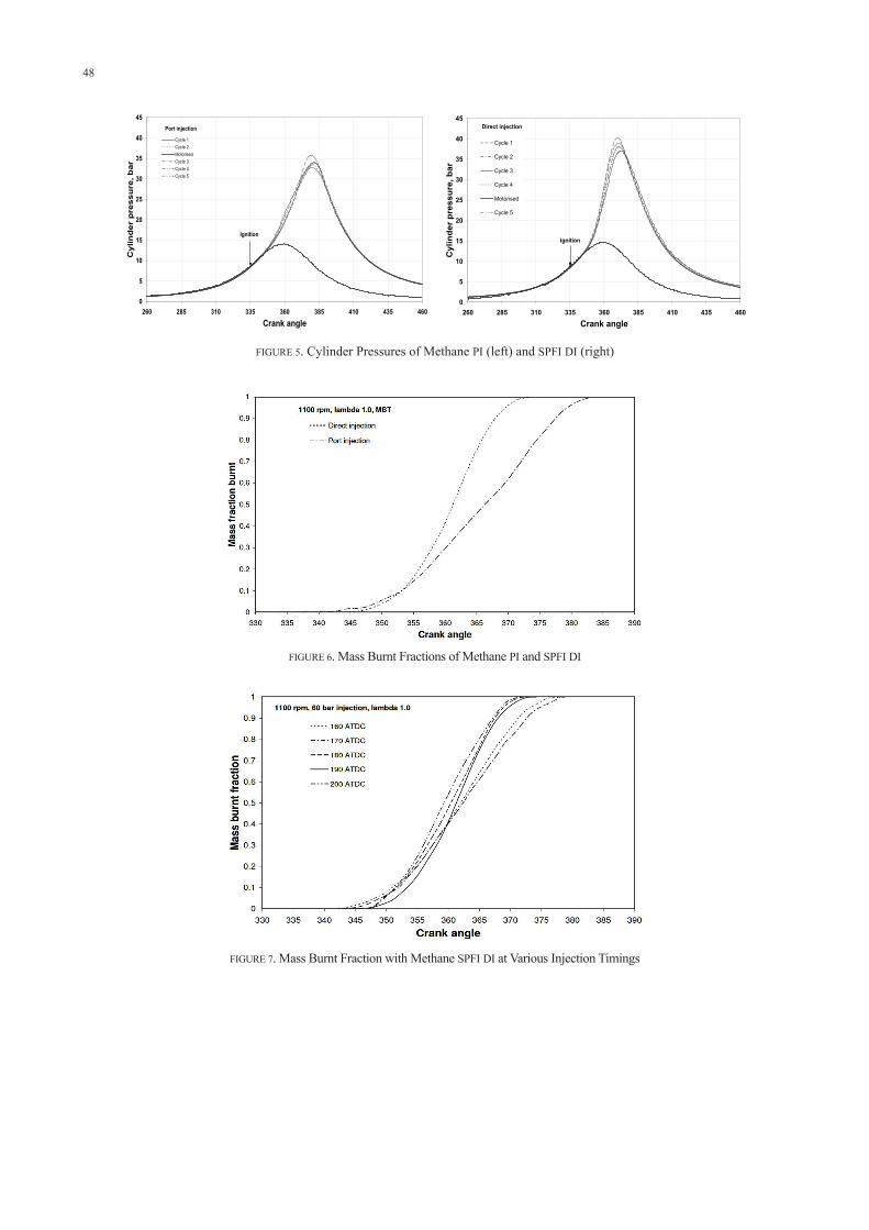
In Figure 5, the cylinder pressure of PI and SPFI DI were plotted at five consecutive cycles. The peak cylinder pressures with SPFI DI are higher than those of PI by 5 bar
averaged. This is due to increased cylinder charge and faster rate of combustion. However, the position of peak pressures for the SPFI DI are 5-10o CA earlier and this caused the lost of positive work which reduced the output power.
In Figure 6 through Figure 10, the normalized mass burnt fraction curve increases from 0 to 1 and then reduces to a certain value at the end of the graphs. These were done to indicate that mass burnt fraction was estimated based on the pressure rise due to combustion, which were obtained by subtracting instantaneous motorized cylinder pressure from instantaneous firing cylinder pressure. When there is no more combustion occurs, the pressure rise due to combustion becomes negative, and the MBF curve reduces to less than 1. Even though it is strongly believed that combustion completeness is not achieved, the value 1 for mass burnt fraction is used to simplify the results.
The first measurement was done to compare the rate of burnt between SPFI direct injections (DI) with those of port fuel injections (PI). Figure 6 shows the result which indicates that the ignition delay is shorter in the case of port injection compared to direct injection. However, the combustion duration in DI method is significantly shorter. The 50% mass burnt fraction or the phasing angle correspond to 2o and 7o ATDC for direct injection and port injection respectively. In the direct injection mode, a greater amount of cylinder charge causes higher pre-combustion pressure, thus sped up the combustion process. The difference in ignition delays on the
(b)
(c)(a)
47
FIGURE 4. Schematic of SPFI Experiment Instrumentation and Data Acquisition System
1. Ricardo E6 Engine, 2. Electric Dynamometer, 3. Spark Plug Fuel Injector, 4. Flywheel, 5. Load Cell, 6. Slotted Disk, 7. Photodiode, 8. Camshaft And Shaft Encoder, 9. Pressure Sensor, 10. Pressure Regulator,11. CNG Tank, 12. Throttle Valve, 13. MOSFET Circuit Controller,
PI SPFI DI
Injection pressure, bar 30 60
IMEP, bar 6.63 6.20
Pindicated, kW 3.04 2.85
ηv, % 72.35 83.43
ηf, indicated, % 26.94 21.84
TABLE 2. Performance of PI Versus SPFI DI at 1100rpm and Stoichiometric Air/Fuel
14. Power Supply Unit, 15. Pulse Generator, 16. Charge Amplifier, 17. Data Acquisition Controller, 18. Fuel Flow Meter, 19. Multislope Manometer, 20. Air Flow Meter, 21. Ignition Unit, 22. Crankshaft, 23. Oscilloscope, 24. Lambda Sensor, 25. Lambda Meter, 26. Battery
48
Port injection
0
5
10
15
20
25
30
35
40
45
260 285 310 335 360 385 410 435 460
Crank angle
Cyl
ind
er p
ress
ure
, bar
Cycle 1Cycle 2MotorisedCycle 3Cycle 4Cycle 5
Ignition
Direct injection
0
5
10
15
20
25
30
35
40
45
260 285 310 335 360 385 410 435 460Crank angle
Cyl
inde
r pr
essu
re, b
ar
Cycle 1
Cycle 2
Cycle 3
Cycle 4
Motorised
Cycle 5
Ignition
FIGURE 5. Cylinder Pressures of Methane PI (left) and SPFI DI (right)
FIGURE 6. Mass Burnt Fractions of Methane PI and SPFI DI
FIGURE 7. Mass Burnt Fraction with Methane SPFI DI at Various Injection Timings
49
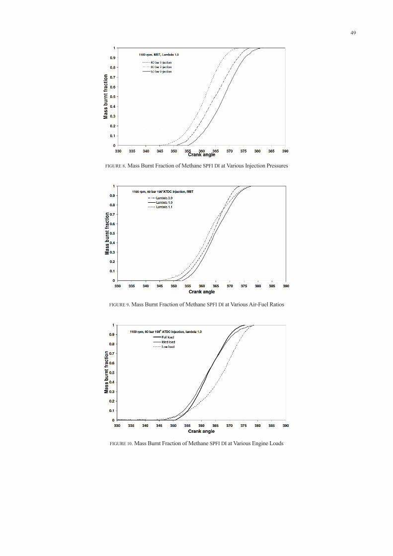
FIGURE 8. Mass Burnt Fraction of Methane SPFI DI at Various Injection Pressures
FIGURE 9. Mass Burnt Fraction of Methane SPFI DI at Various Air-Fuel Ratios
FIGURE 10. Mass Burnt Fraction of Methane SPFI DI at Various Engine Loads

50
other hand is due to the longer time taken to develop initial flame kernel in the more dense charge if direct injection.
The effects of different injection timings with respect to crank angle are shown on Figure 7. As mentioned earlier, the optimal performance was achieved with injection at 170o BTDC where the MBF curve is the steepest. The combustions at earlier injection show longer combustion periods but shorter ignition delay, and the later injections result in shorter combustion durations and relatively longer ignition delay, which agree with the earlier findings (Huang et al. 2003).
The effects of injection pressure on SPFI CH4 DI MBF are shown in Figure 8. Injection pressure has significant effect on the combustion behavior. The ignition delays are well distinguished with 60 bar injection yielding the shortest delay and 50 bar results in the longest. The ignition time for all injection pressures is 25oBTDC (345o CA on the graph). Combustion duration remain the same for all injection pressures, but the 80 bar injection shows faster early burning stage and slower later stage. At this particular operational set up, the 60 bar injection yields best performance.
The effect of mixture stoichiometry is shown in Figure 9. At lambda 1.1, combustion duration is the longest, and it decreases as mixtures get richer. However, ignition delay trend indicates inconsistency with lambda values showing values of 10o, 15o and 18o CA for lambda 1.1, 0.9 and 1.0 respectively.
The MBF behavior with different load conditions is shown in Figure 10. Combustion duration increases with decreasing loads but ignition delay is shortest at lowest load conditions. Decreasing load means reducing charge amount in each cycle which results in lowering overall cylinder pressure. This in return contributes to the increase in combustion duration.
The combustion durations for direct injection of natural gas is shorter than those of port injection as reported earlier (Huang et al. 2003 & Hassaneen et al. 1998). The time between injection and ignition also has strong effect on the combustion behavior, and subsequently, the engine performance (Zeng et al. 2006). However, all these reports were based on combustion chamber with close-to-optimal arrangements of fuel injection and spark plug, which are almost pointing towards each other. The direct injection of natural gas using SPFI has a different orientation of fuel injection and spark ignition where fuel is injected away from the point of ignition. The spray is weakly guided to the spark plug by the piston movement as compression stroke advances towards ignition. As a result, mixture formation and strength of mixture at the vicinity of spark plug electrodes may not be optimized.
CONCLUSION
Based on the observation and figures presented, these are the conclusions in terms of the burning behavior of methane in a spark plug fuel injector direct injection operation of the engine. SPFI DI operation of methane results in 11% increased in volumetric efficiency which leads to increased heating value of cylinder charge per cycle. Combustion duration in SPFI methane DI operation is shorter than the one of PI. However, combustion in DI injection is slower at the earlier part and
faster at the later part of combustion duration compared to PI. Based on the MBF analysis, the optimal fuel injection timing is 170o BTDC. Combustion durations were not changed with different injection pressures but ignition delay was affected by this variation. However, there is no direct correlation between injection pressure and ignition delay which is most probably due to the effect of charge flow difference. Changing mixture stoichiometry affects the magnitude of ignition delay. Combustion duration, on the other hand increases with leaner mixture. Different load conditions have significant effect on combustion process. Lower loads tend to increase combustion duration but shorten ignition delay.
REFERENCES
Brunt, M. F. J., Rai, H. & Emtage, A. L. 1998. The Calculation of Heat Release from Engine Cylinder Pressure Data. SAE 981052.
Chun, K. M. & Heywood, J. B. 1987. Estimating Heat-Released and Mass of Mixture Burned from Spark-Ignition Engine Pressure Data. Combustion Science and Technology 54: 133-143.
Egnell, R. 1998. Combustion diagnostics by means of multizone heat release analysis and NO calculation. SAE 981424.
Gatowski, J. A., Balles, E. N., Chun, K. M., Nelson, F. E., Ekchian, J. A. & Heywood, J. B. 1984 Heat release analysis of engine pressure data. SAE 841359.
Geuzennec, Y. G. & Hamama, W. 1999. Two-zone heat release analysis of combustion data and calibration of heat transfer correlation is an IC engine. Transaction of SAE. SAE 1999-01-0218.
Goto, Y. 1999. Mixture Formation and Ignition in a Direct Injection Natural Gas Engine. JSME International Journal Series B 42: 268-274.
Hassaneen, A. E., Varde, K. S., Bawady, A. H. & Morgan, A. A. 1998. A Study of The Flame Development and Rapid Burn Durations in a Lean-Burn Fuel Injected Natural Gas S. I. Engine. SAE 981384.
Heywood, J. B. 1998. Internal Combustion Engines Fundamentals. New York: McGraw Hill.
How Hoey Geok, Taib Iskandar Mohamad, Shahrir Abdullah, Yusoff Ali, Azhari Shamsudeen, Elvis Adril. 2009. Experimental Investigation of Performance and Emission of a Sequential Port Injection Natural Gas Engine. European Journal of Scientific Research 30 (2): 204-214.
Huang, Z., Shiga, S., Ueda, T., Nakamura, H., Ishima, T., Obokata, T., Tsue, M. & Kono, M. 2003. Combustion Characteristics of Natural-gas Direct-injection Combustion under Various Fuel Injection timings. Journal of Automobile Engineering 21: 393 – 401.
Jermy, M. C., Harrison, M., Vuorenskoski, A. K., Mohamad, T. I., Kaparis, E. & Macartney, M. 2004. Overcoming Power Loss in LPG/ Propane and CNG Conversions of Vehicle Engines. Proceedings of The International Conference on Vehicle Alternative Fuel Systems and
51
Environmental Protection, pp. 211-216. Dublin City University, Ireland.
Mohamad, T. I., Harrison, Ma., Jermy, M. & How, H. G. 2010. The Structure of High Pressure Gas Jet from Spark Plug Fuel Injector for Direct Fuel Injection in Spark Ignition Engine. Journal of Visualization 13(1): 121-131.
Mohamad, T. I., Jermy, M. C., & Harrison, M. 2003. Direct Injection of Compressed Natural Gas in Spark Ignition Engine, Proceedings of The 3rd International Conferences on Advances in Strategic Technologies, vol. II, pp. 927-932. Kuala Lumpur, Malaysia.
Rassweiler, G. M. & Withrow, L. 1938. Motion Pictures of Engines Flames Correlated with Pressure Cards. SAE Transaction 42(5): 85-204.
Stone, C. R. & Green-Armytage, D. I. 1987. Comparison of Methods for the Calculation of Mass Fraction Burnt from Engine Pressure-Time Diagrams. Proc. Institute of Mechanical Engineers part D1. 201
Zeng, K., Huang, Z., Liu, B., Liu, L., Jiang, D., Ren, Y. & Wang, J. 2006. Combustion Characteristics of a Direct Injection Natural Gas Engine under various Fuel Injection Timings. Applied Thermal Engineering 26: 806-813.
Taib Iskandar MohamadDepartment of Mechanical and Materials Engineering, Faculty of Engineering & Built Environment,Universiti Kebangsaan Malaysia, 43600 Bangi,Selangor, Malaysia
*Corresponding author; e-mail: [email protected]
Received Date : 19th March 2009 Accepted Date : 21st July 2010
