t'e - core.ac.uk · /lj~ t'e~(11.191 laporan akhir projek penyelidikan jangka pendek...
TRANSCRIPT
/ lJ~
~(t'E 11.191
Laporan Akhir Projek PenyelidikanJangka Pendek
Purification of Carbon NanotubesProduced from Catalytic Decomposition.,
of Methane
byDr. Sharif Hussein Sharif Zain
•,
Prof. Abdul Rahman Mohamed
IlIIHMIUNIVERsm SAINS MALAYSIA
LAPORAN AKHIR PROJEK PENYELIDlKAN JANGKA PENDEKFINAL REPORT OF SHORT TERM RESEARCH PROJECTSila kemukakan laporan akhir ini melalui Jawatankuasa Penyelidikan di PusatPengajian dan Dekan/Pengarah/Ketua Jabatan kepada Pejabat Pelantar Penyelidikan
2. Pusat Tanggungjawab(pTJ): Pusat Pengajian Kejuruteraan KimiaSchooVl)epartrnent
4. Tajuk Projek:Title ofProject Purification of Carbon Nanotubes Produced from Catalytic DecomposotionofMethane
i) Pencapaian objektif projek:Achievement ofproject objectives D D D ~ D
ii) Kualiti output:Quality ofoutputs D D D D ~
iii) Kualiti impak:Quality of impacts D D D ~ D
iv) Pemindahan teknologilpotensi pengkomersialan:Technology transfer/commercialiiation potential D D D 0 D.,
v) Kualiti dan usahasama :Quality and intensity ofcollaboration D D ~ D D
vi) Penilaian kcpentingan secara keseluruhan:Overall assessment ofbenefits D D D [TI D
Laporan Akhir Projek Penyelidikan Jangka PendekFinal Report OJShort Term Research Project
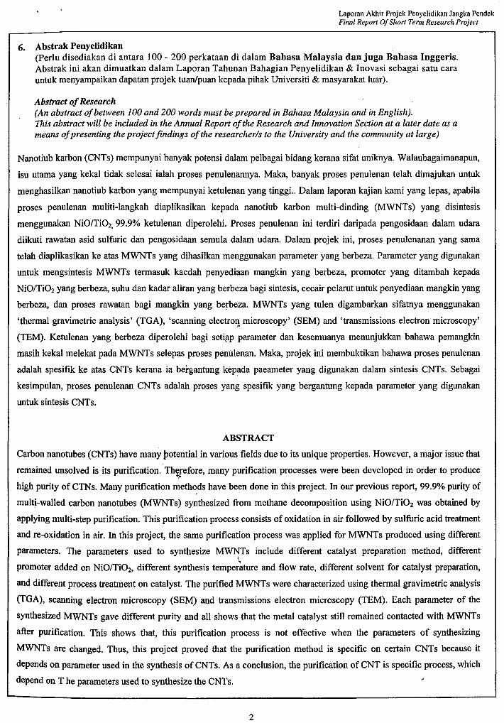
6. Abstrak Penyelidikan(Perlu disediakan di antara 100 - 200 perkataan di dalam Bahasa Malaysia dan juga Bahasa Inggeris.Abstrak ini akan dimuatkan dalam Laporan Tahunan Bahagian Penyelidikan & Inovasi sebagai satu carauntuk menyampaikan dapatan projek tuanlpuan kepada pihak Universiti & masyarakat luar).
Abstract ofResearch(An abstract ofbetween 100 and 200 words must be prepared in Bahasa Malaysia and in English).This abstract will be included in the Annual Report ofthe Research and Innovation Section at a later date as ameans ofpresenting the projectjindings ofthe researcher/s to the University and the community at large)
Nanotiub karbon (CNTs) mempunyai banyak potensi dalam pelbagai bidang kerana sifat uniknya. Walaubagaimanapun,
isu utama yang kekal tidak selesai ialah proses penulenannya. Maka, banyak proses penulenan telah dimajukan untuk
menghasilkan nanotiub karbon yang mempunyai ketulenan yang tinggi.. Dalam laporan kajian kami yang lepas, apabila
proses penulenan muliti-Iangkah diaplikasikan kepada nanotiub karbon multi-dinding (MWNTs) yang disintesis
menggunakan NiO/Ti02, 99.9% ketulenan diperolehi. Proses penulenan ini terdiri daripada pengosidaan dalam udara
diikuti rawatan asid sulfuric dan pengosidaan semula dalam udara. Dalam projek ini, proses penulenanan yang sarna
telah diaplikasikan ke atas MWNTs yang dihasilkan menggunakan parameter yang berbeza. Parameter yang digunakan
untuk mengsintesis MWNTs termasuk kaedah penyediaan mangkin yang berbeza, promoter yang ditambah kepada
NiO/Ti02 yang berbeza, suhu dan kadar aliran yang berbeza bagi sintesis, cecair pelarut untuk penyediaan mangkin yang
berbeza, dan proses rawatan bagi mangkin yang be~beza. MWNTs yang tulen digambarkan sifatnya menggunakan
'thermal gravimetric analysis' (TGA), 'scanning electr0ll microscopy' (SEM) and 'transmissions electron microscopy'
(TEM). Ketulenan yang berbeza diperolehi bagi setiflP parameter dan kesemuanya menunjukkan bahawa pemangkin
masih kekal melekat pada MWNTs selepas proses penillenan. Maka, projek ini membuktikan bahawa proses penulenan
adalah spesifik ke atas CNTs kerana ia bergantung kepada paeameter yang digunakan dalam sintesis CNTs. Sebagai
kesimpulan, proses penulenan CNTs adalah proses yang spesifik yang bergantung kepada parameter yang digunakan
untuk sintesis CNTs.
ABSTRACT
Carbon nanotubes (CNTs) have many potential in various fields due to its unique properties. However, a major issue that
remained unsolved is its purification. ThS/efore, many purification processes were been developed in order to produce
high purity of CTNs. Many purification methods have been done in this project. In our previous report, 99.9% purity of
multi-walled carbon nanotubes (MWNTs) synthesized from methane decomposition using NiO/Ti02 was obtained by
applying multi-step purification. This purification process consists of oxidation in air followed by sulfuric acid treatment
and re-oxidation in air. In this project, the same purification process was applied for MWNTs produced using different
parameters. The parameters used to synthesize MWNTs include different catalyst preparation method, different,,promoter added on NiO/Ti02, different synthesis temperature and flow rate, different solvent for catalyst preparation,
and different process treatment on catalyst. The purified MWNTs were characterized using thermal gravimetric analysis
(TGA), scanning electron microscopy (SEM) and transmissions electron microscopy (TEM). Each parameter of the
synthesized MWNTs gave different purity and all shows that the metal catalyst still remained contacted with MWNTs
after purification. This shows that, this purification process is not effective when the parameters of synthesizing
MWNTs are changed. Thus, this project proved that the purification method is specific on certain CNTs because it
depends on parameter used in the synthesis of CNTs. As a conclusion, the purification of CNT is specific process, which
depend on T he parameters used to synthesize the CNTs.
2
Laporan Akhir Projek Penyelidikan Jangka PendekFinal Report OfShort Term Research Project
. 7. SUa sediakan laporan teknikallengkap yang menerangkan keseluruhan projek ini.• [SUa' gunakan kertas berasingan]
Applicant are required to prepare a Comprehensive Technical Report explaining the project.(This report must be appended separately)
Senaraikan kata kunci yang mencerminkan penyelidikan anda:List the key words that reflects your research:
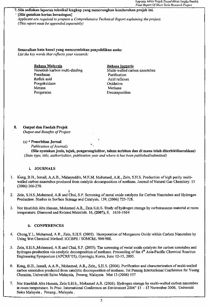
Bahasa MalaysiaNanotiub karbon multi-dindingPemilenanRefluk asidPengoksidaanMetanaPenguraian
8. Output dan Faedah ProjekOutput and Benefits ofProject
Bahasa InggerisMulti-walled carbon nanotubesPurificationAcid refluxes
OxidationMethane
Decomposition
(a) * Penerbitan JurnalPublication ofJournals(SUa nyatakanjenis, tajuk, pengarangfeditor, tahun terbitan dan di mana telah diterbitldiserahkan)
(State type, title, author/editor, publication year and where it has been published/submitted)
i. JOURNALS
I. Kong, B.H., Ismail, AA.B., Mahayuddin, M.E.M. Mohamed, A.R., Zein, S.H.S. Production ofhigh purity multiwalled carbon nanotubes produced from catalytic decomposition of methane. Journal ofNatural Gas Chemistry. 15(2006) 266-270.
t2. Zein, S.H.S.,Mohamed, A.R andChai, S.P. Screening of metal oxide catalysts for Carbon Nanotubes and Hydrogen
Production. Studies in Surface Scie~ and Catalysis. 159, (2006) 725-728.
3. Nor Hasridah Abu Hassan, Mohamed AR., Zein S.H.S. Study ofhydrogen storage by carbonaceous material at roomtemperature. Diamond and Related Materials. 16, (2007), 8, 1656-1664.
ii. CONFERENCES
4. Chong,Y.L, Mohamed, AR., Zein, S.H.S. (2005). Incorporation ofManganese Oxide within Carbon Nanotubes byUsing Wet Chemical Method. ICCBPE / SOMChE. 904-908.
5. Zein, S.H.S.,Mohamed, A.R and Chai, S.P. (2005). The screening of metal oxide catalysts for carbon nanotubes andhydrogen production via catalytic decomposition of methane. Proceeding of the 4th Asia-Pacific Chemical ReactionEngineering Symposium (APCRE'05), Gyeongju, Korea, June 12-15,2005.
6. Kong, B.H., Ismail, AA.B., Mohamed, AR., Zein" S.H.S. (2006). Purification and characterization of multi-walledcarbon nanotubes produced from catalytic decomposition of methane. 1st Penang International Conference for YoungChemists, Universiti Sains Malaysia, Penang, Malaysia. Mat 13 (2006) 157
7. Nor Hasridah Abu Hassan, Zein S.H.S., Mohamed A.R. (2006). Hydrogen storage by multi-walled carbon nanotubesat room temperature. In Proc. International Conference on Enviroment 2006" 13 - 15 November 2006, UniversitiSains Malaysia, Penang, Malaysia.
3
Laporan Akhir Projek Penyelidikan Jangka PendekFinal Report OfShort Term Research Project
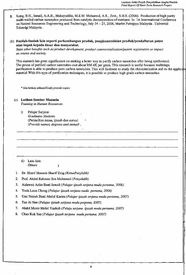
8. Kong, B.H., Ismail, A.A.B., Mahayuddin, M.E.M. Mohamed, A.R., Zein" S.H.S. (2006). Production of high puritymulti-walled carbon nanotubes produced from catalytic decomposition of methane. In: 1st Intermational Conferenceon Natural Resources Engineering and Technology, July 24 - 25, 2006, Mariot Putrajaya Malaysia. UniversitiTeknolgi Malaysia.
(b) Faedah-faedah lain seperti perkembangan produk, pengkomersialan produk/pendaftaran patenatau impak kepada dasar dan masyarakat.State other benefits such as product development, product commercialisation/patent registration or impacton source and society.
This research has great significance on seeking a better way to purify carbon nanotubes after being synthesized.The prices of purified carbon nanotubes cost about RM 4K per gram. This research is useful because multistepspurification is able to produce pure carbon nanotubes. This will facilitate to study the characterization and so the applicmaterial.With this type of purification techniques, it is possible to produce high grade carbon nanotubes.
* Sila berikan salinanlKindly provide copies
(c) Latihan Sumber ManusiaTraining in Human Resources
i) Pelajar Sarjana:Graduates Students(Perincikan nama, ijazah dan status) "(Provide names, degrees and status".
ii) Lain-lain:Others
1. Dr. Sharif Hussein Sharif Zei~ (KetuaPenylidik)
2. Prof. Abdul Rahman Bin Mohamed (Penyelidik)
3. Aidawati Azlin Binti Ismail (Pelajar ijazah serjana muda pertama, 2006)
4. Yeoh Loon Chong (Pelajar ijazah serjana muda pertama, 2006)
5. Umi Natrah Binti Abdol Karim (Pelajar ijazah serjana muda pertama, 2007)
6. Tan Ai Nee (Pelajar ijazah serjana muda pe1ifama, 2007),7. Abdul Munir Mohd Yaakob (Pelaja serjana ijazah muda pertama, 2007)
8. Chan Kok San (pelajar ijazah serjana muda pertama, 2007)
4
Laporan Akhir Projek Penyelidikan Jangka PendekFinal Report QfShort Term Research Project
8. Kong, B.H., Ismail, A.A.B., Mahayuddin, M.E.M. Mohamed, A.R., Zein" S.H.S. (2006). Production ofhigh puritymulti-walled carbon nanotubes produced from catalytic decomposition ofmethane. In: 1st Intermational Conferenceon Natural Resources Engineering and Technology, July 24 - 25,2006, Mariot Putrajaya Malaysia. UniversitiTeknolgi Malaysia.
(b) Faedah-faedah lain seperti perkembangan produk, pengkomersialan produk/pendaftaran patenatau impak kepada dasar dan masyarakat.State other benefits such as product development, product commercialisation/patent registration or impacton source and society.
* Sila berikan salinan/Kindly provide copies
(c) Latihan Sumber ManusiaTraining in Human Resources
i) Pelajar Sarjana:Graduates Students(Perincikan nama, ijazah dan status)(Provide names, degrees and status)
ii) Lain-lain:Others
1. Dr. Sharif Hussein Sharif Zein (KetuaPenylidik)
2. Prof. Abdul Rahman Bin Mohamed (Penyelidik)
3. Aidawati Azlin Binti Ismail (Pelajar ijazah serjana muda pertama, 2006)
4. Yeoh Loon Chong (Pelajar ijazah serjana muda pertama, 2006)
5. Umi Natrah Binti Abdol Karim (Pelajar ijazah serjana muda pertama, 2007)
6. Tan Ai Nee (Pelajar ijazah serjana muda pertama, 2007)
7. Abdul Munir Mohd Yaakob (Pelaja serjana r ijazah muda pertama, 2007)
8. Chan Kok San (Pelajar ijazah serjana muda pertama, 2007)
4
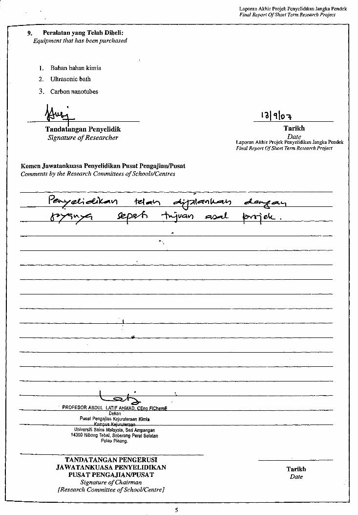
9. Peralatan yang Telah Dibeli:Equipment that has been purchased
I. Bahan bahan kimia
2. Ultrasonic bath
3. Carbon nanotubes
~gan PenyelidikSignature ofResearcher
Komen Jawatankuasa Penyelidikan Pusat PengajianIPusatComments by the Research Committees 0/Schools/Centres
Laporan Akhir Projek Penyelidikan Jangka PendekFinal Report OfShort Term Research Project
TarikhDate
Laporan Akhir Projek Penyelidikan Jangka PendekFinal Report OfShort Term Research Project
PROFESOR ABDUL LATIF AHMAD, CEng FIChemEDekan
Pusal Pengajian Kejuruleraan KimiaI.<ampu$ l.<~unll~~aaR
Universiti Sains Malaysia, Seri Ampangan14300 Nibong Tebal, Seberang Perai Selatan
Pulau Pinang.
..
TANDATANGAN PENGERUSIJAWATANKUASA PENYELIDlKAN
PUSAT PENGAJIANIPUSATSignature o/Chairman
[Research Committee ofSchool/CentreJ
5
TarikhDate
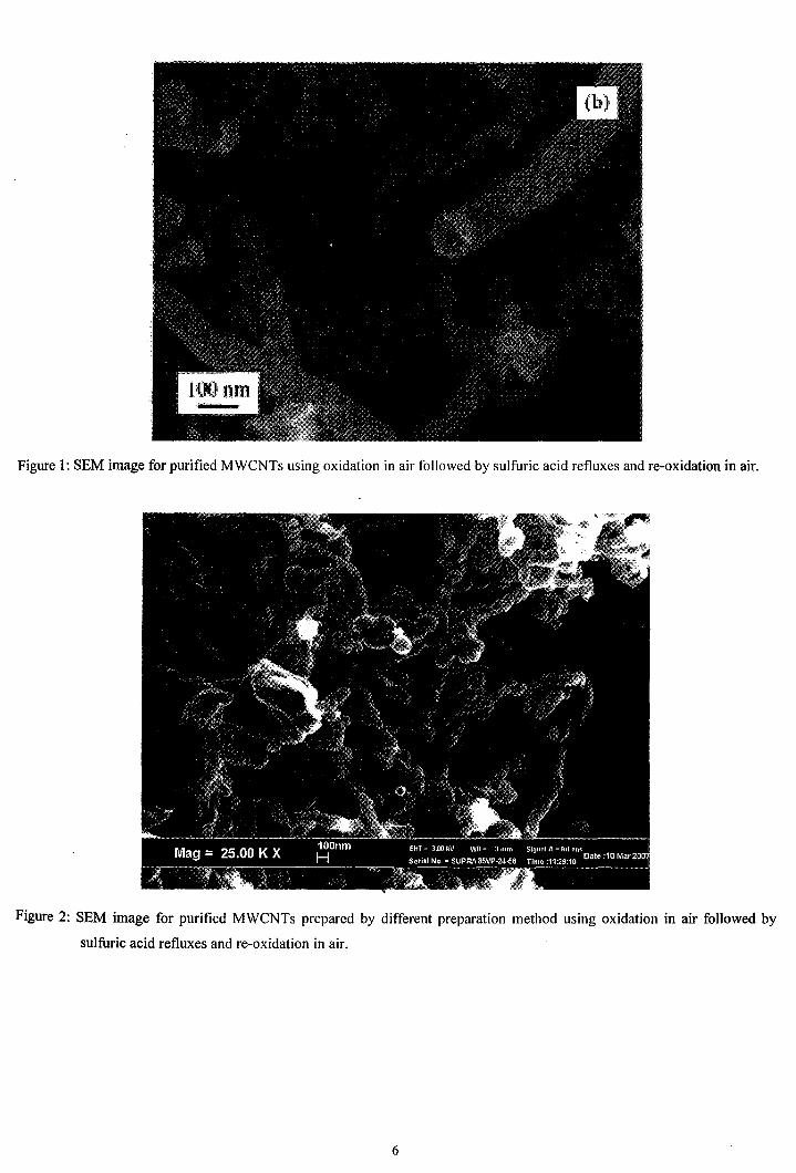
Figure 1: SEM image for purified MWCNTs using oxidation in air followed by sulfuric acid retluxes and re-oxidation in air.
Figure 2: SEM image for purified MWCNTs prepared by different preparation method using oxidation in air followed by
sulfuric acid refluxes and re-oxidation in air.
6
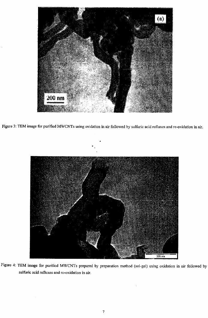
Figure 3: TEM image for purified MWCNTs using oxidation in air followed by sulfuric acid refluxes and re-oxidation in air.
...
Figure 4: TEM image for purified MWCNTs prepared by preparation method (sol-gel) using oxidation in air followed by
sulfuric acid refluxes and re-oxidation in air.
7
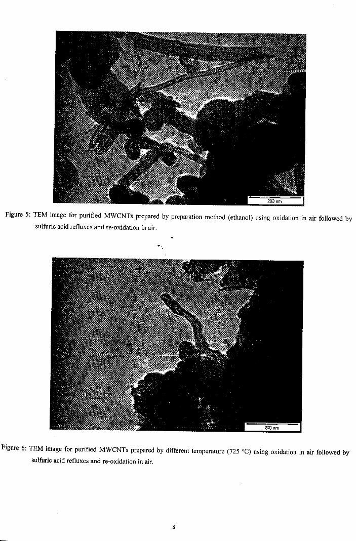
Figure 5: TEM image for purified MWCNTs prepared by preparation method (ethanol) using oxidation in air followed by
sulfuric acid refluxes and re-oxidation in air.
Figure 6: TEM image for purified MWCNTs prepared by different temperature (725°C) using oxidation in air followed by
sulfuric acid refluxes and re-oxidation in air.
8
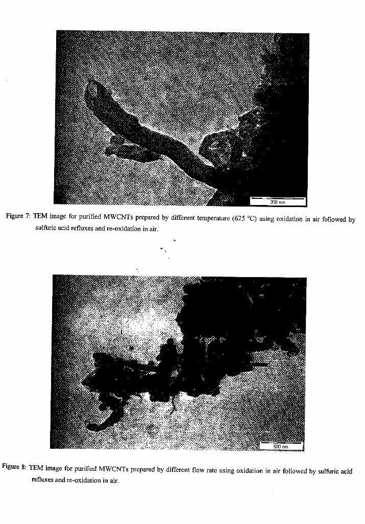
Figure 7: TEM image for purified MWCNTs prepared by different temperature (625°C) using oxidation in air followed by
sulfuric acid refluxes and re-oxidation in air.
...
Figure 8: TEM image for purified MWCNTs prepared by different flow rate using oxidation in air followed by sulfuric acid
refluxes and re-oxidation in air.
9
200 400 600Tllmpell'ataM ("C:')
20
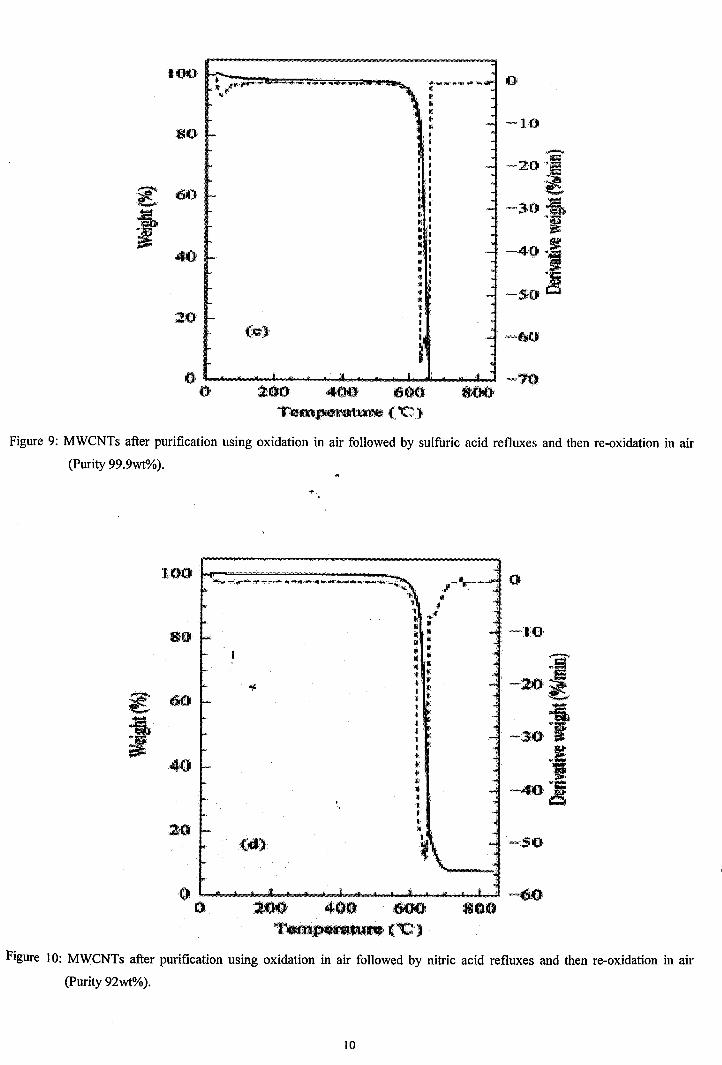
Figure 9: MWCNTs after purification using oxidation in air followed by sulfuric acid refluxes and then re-oxidation in air
(Purity 99.9wt%).
-10
o~"r---Ii\
"~x
Ii II.. IIIII II!II IIJf.:"'I •I' "I II
I •III1II
"tI>IIiI
"III,II
,,
(dl
.200 400 600T•.D~•.("C··)
Figure 10: MWCNTs after purification using oxidation in air followed by nitric acid refluxes and then re-oxidation in air
(Purity 92wt%).
10
lO'!:) -- - -- -, --~---'- - - ~"'- ..~ ~
"
(c)
2,00 400 !6(10
T~ilJpa;awPeCC)800
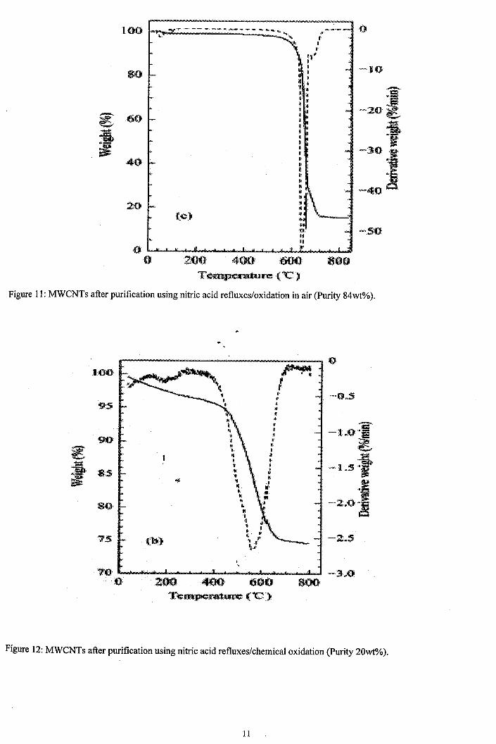
Figure 11: MWCNTs after purification using nitric acid refluxes/oxidation in air (Purity 84wt%).
AlI..'I•~'t_<~
I,"II'IIII
".."..
11'I1'1II' ..It. .t"'1''i""
~f
l'II'..I
"I~
I'I!r
"I•II'I:Ii
,1if..III
,01
.,200 400 600Te~llJUte("C)
Figure 12: MWCNTs after purification using nitric acid refluxes/chemical oxidation (Purity 20wt%).
11
%
Soo-pe 14 (1) 02.02.200716:01:32limn
00
step -4.3202% ·0.05
-0.4413 rrg00 Residul 95.6300%
9.7680rrgLeftUnil 3O.50'CRighlUml 89.19 'C step -0.8422% -0.10
70 -86.0242e-03 rrgResidl.e 94.78lB%
9.6820rrg
00 LeftUnil 89.19'C step -55.nB9%RightUml 406.38'C -5.6974 rrg -0.15
Residi.e 39.0Il00 % i50
3.9846rrg
JLeftUnil 406.38'CRighlUml 849.67'C
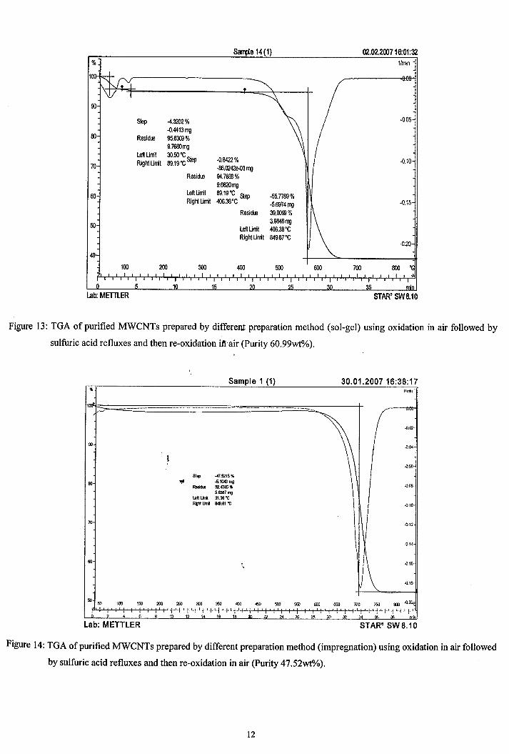
Figure 13: TGA of purified MWCNTs prepared by differenJ: preparation method (sol-gel) using oxidation in air followed by
sulfuric acid refluxes and then re-oxidation itiair (Purity 60.99wt%).
00
70
00
Sample 1 (1)
51,,!, -47.5215 %"l' -5.1043mg
_ 52.4785%
5.6367 mgleft Lint 31.36"CRigIt lint &l9.91"C
,,
30.01.2007 16:38:171!mio
{).02.
4.00
"'.re
.0.10
.0.12
-0.14
\.(l.IS"
.0.18
600 fl50 700 750 ~ .O2!l(
? 6 8 10
Lab: METTLER4 •• .~ .,;, ~ '4 "" '" '" 3? ".',a '" mo
STARe SW 8.10
Figure 14: TGA of purified MWCNTs prepared by different preparation method (impregnation) using oxidation in air followed
by sulfuric acid refluxes and then re-oxidation in air (Purity 47.52wt%).
12
31 01 200716'38'00Sarqje 12 (1)% 1/mn
1
90Step -22.5261 %
-2.3914rt'Q -0.05Residl.e 77.4~%
80 8.2248rt'Q
\Left Unit 30.18 'C -Right Unit 675.24'C Step -30.7118%
-3.2604rt'Q-0.10Residle 46.7621 %70
4.9644rt'QLeft Unit 675.24'CRight Unit 850.39'C
80-0.15
50~ \
100 200 300 400 500 600 700 6OO·0.2(J;Ir I
0 5 10 15 20 25 30 35 I1inLab: METTlER STAR" SW8.10
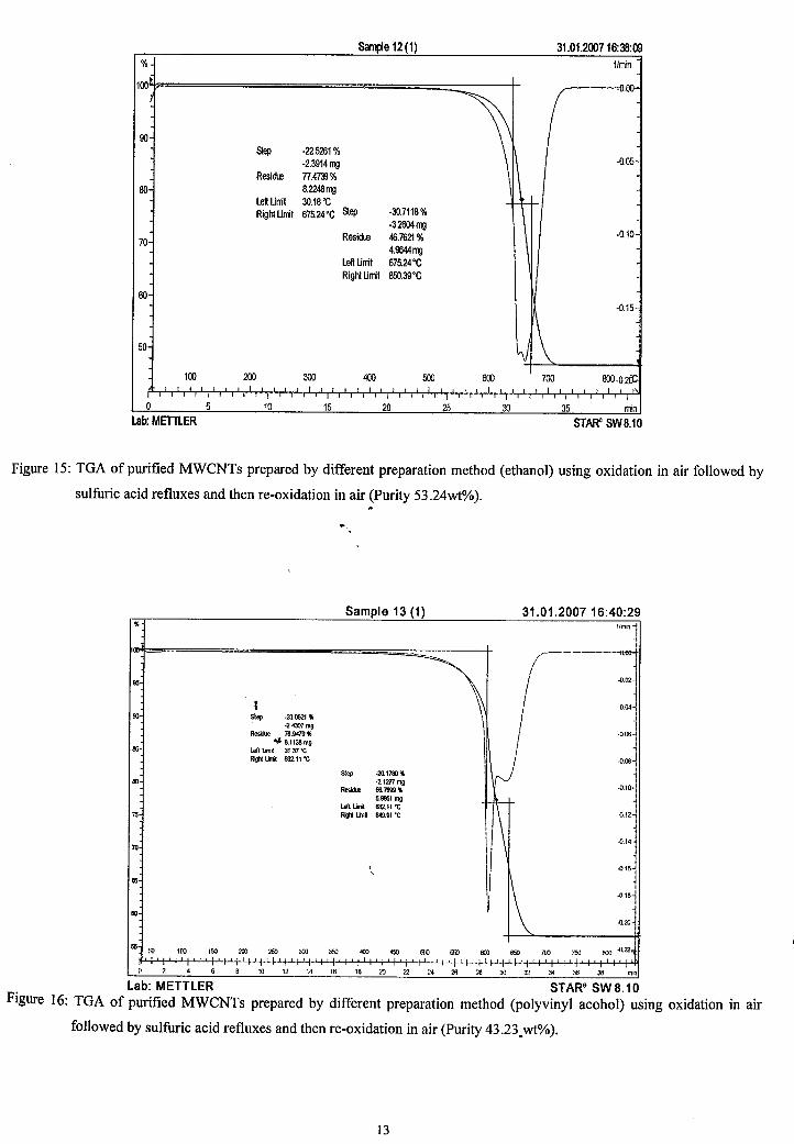
Figure 15: TGA of purified MWCNTs prepared by different preparation method (ethanol) using oxidation in air followed by
sulfuric acid refluxes and then re-oxidation in air (Purity 53.24wt%)."
31.01.200716:40:29Sample 13 (1)'II lImi.'1
.j
..
\/-----------1
95 ~ •.jt -004
00 Slep ·23.0521 'II \·2.4307mgR...... 76.9479'11 01"
tIjI 8.1138mg I95 left lint 3t.37"CR\lhIlOnl 632.11"C I -0.06
step ·20. t78)'1160 -2.1271 mg
-0,10- 86._'11U66tmg
~lefllinl 632.11"C
75 R\lhIlOnl 849,91 ·C ..Q.12
-o.14~
70
, .01SJ,ll5
1\ -0.18
60-0.20'
56!ill 100 tOO :100 2SJ 300 300 <00 4&l tim !i» 600 eoo 700 ;"9] trn -0.22
0 2 4 6 6 10 t2 14 16 16 20 Z! 24 26 ::'3 ~ 32 34 36 :,. min
lab: METTlER STARe SW 8.1 0Figure 16: TGA of purified MWCNTs prepared by different preparation method (polyvinyl acohol) using oxidation in air
followed by sulfuric acid refluxes and then re-oxidation in air (Purity 43.23_wt%).
13
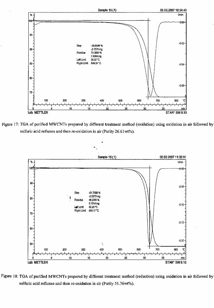
%
S~e 15(1) 05.02.200710:54:431/rrin
95
Step -26.8046%90 -2.7575rrg
Residt.e 73.3863%7.8064rrg
LeftUrril 30.57 'C85 RighlUrril 849.31 'C
80
75
-0.02
-0.04
-0.06
100
o 5Lab: METTLER
200
10
300
15
400
20
500
25
800
30
700 800 'C
35 rrinSTARe SW8.10
Figure 17: TGA of purified MWCNTs prepared by different treatment method (oxidation) using oxidation in air followed by
sulfuric acid refluxes and then re-oxidation in air (Purity 26.61 wt%).
....
&mpe 16(1) 05 02.200711'32:51% 1/min
1 ·V.w·
90-0.05
Step -51.7598%
80 I -5.5273mgResid.e 48.2393%
5.1514mg -0.104i\Urril 3O.23'CRight Limil 850.17'C
70
\-0.15
60
1\ -02050
,,
100 200 300 400 500 600 700 800 'C,..:
I I I I I
0 5 10 15 20 25 30 35 min
Lab: METTLER STARe SW8.10
Figure 18: TGA of purified MWCNTs prepared by different treatment method (reduction) using oxidation in air followed by
sulfuric acid refluxes and then re-oxidation in air (Purity 51.76wt%).
14
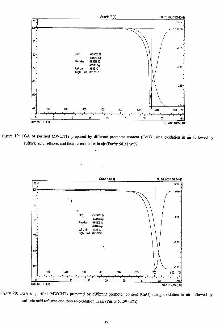
San1JIe 7 (1) 30.01.200716:40:42% 1/min
90
-0.05
80 Step -58.3062%-5.9878mg
ResidLe 41.6008%4.2818mg
-0.1070 Left Unit 31.65'CRighlUmit 850.30'C
80
-0.15
50
-0.2040 100 200 300 400 500 600 700 800 'C
0 5 10 15 20 25 30 35 minLab: METTLER STARe SW8.10
Figure 19: TGA of purified MWCNTs prepared by different promoter content (CoO) using oxidation in air followed by
sulfuric acid refluxes and then re-oxidation in air (Purity 58.31 wt%).
Sanpe 8(1) 30.01.200716:44:41% 1/min I
STARe SW8.1035 rrin3025
500
20
400
15
300
10
200100
o 5
"" .~~Step -51.5895%
90 -5.2049mgResidLe 48.4105%
4.8842mgLeft Unit 31.38'CRighlUrrit 850.67'C
70
-0.10,,
eo
50
Lab: METTLER
Figure 20: TGA of purified MWCNTs prepared by different promoter content (CuD) using oxidation in air followed by
sulfuric acid refluxes and then re-oxidation in air (Purity 51.59 wt%).
15
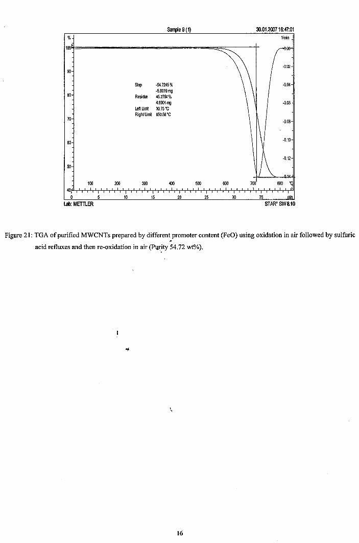
%
sarpe9(1) ~.O1.200716:47:01
1/nin
-0.0290
Step -54.7245% -0.04
SO-5.8019 rTJJ
Resim.e 45.2754%4.8001rTJJ ·0.06
left Unit 30.75 'CRight Unit 850.58'C
70 -0.08
SO-0.10
-0.12
50
100 200 300 400 500 800 700 800 'C40
0 5 10 15 20 25 30 35 nin
Lab: MET1LER STARe SW&10
Figure 21: TGA of purified MWCNTs prepared by different promoter content (FeO) using oxidation in air followed by sulfuric~
acid refluxes and then re-oxidation in air (Purity 54.72 wt%).
\,
16
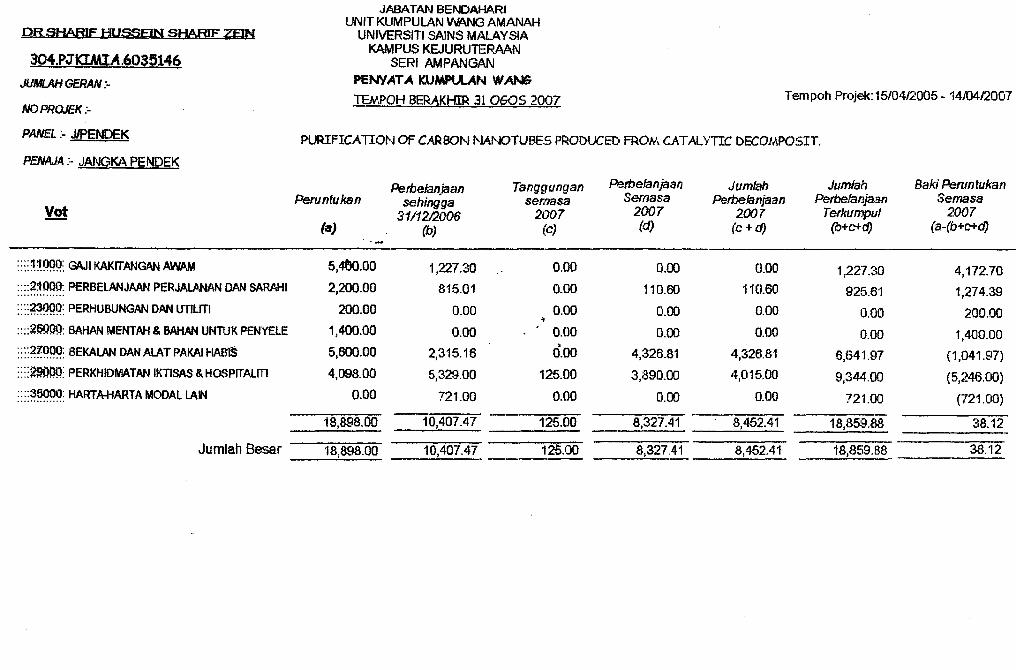
Petbelanjaan Tanggungan Perbefanjaan Jumlah Jumlah Baki PerunlukanPeruntukan sehingga semasa Semasa PerbeJanjaan Perbefanjaan Semasa
~ 3'111212006 2007 2007 2007 Terkumpul 2007(a) (b) (c) (d) (c+d) (b+C+d) (a-(b+c+d)
::::~~@q: Gt\J1 KAKITANGAN AWP~ 5,4tlo.00 1,227.30 0.00 0.00 0.00 1,227.30 4,172.70::::21000: PERBElANJMN PERJALANAN DAN SARAHI 2,200.00 815.01 0.00 110.60 110.60 925.61 1,274.39...............
::::?~99: PERHUBUNGAN DAN UTllm 200.00 0.00 0.00 0.00 0.00 0.00 200.00;t
::::~l?OOO: BAHAN MENTAH & BAHAN UWlUK PENYElE 1,400.00 0.00 0.00 0.00 0.00 0.00 1,400.00:: ::~r:~~: BEKAlAN DAN ALAT PAKAI HAB'$ 5,600.00
>2,315.16 0.00 4,326.81 4,326.81 6,641.97 (1,041.97)
::::~QQ: PERKHIDMATAN IKTISAS&HOSPITAUTI 4,098.00 5,329.00 125.00 3,890.00 4,015.00 9,344.00 (5,246.00)::::~~: HARTA-HARTA MODAL LAIN 0.00 721.00 0.00 0.00 0.00 721.00 (721.00)
18,898.00 10,407.47 125.00 8,327.41 8,452.41 18,859.88 38.12
Jumlah Baser 18:898.00 10,407.47 125.00 8,327.41 8,452.41 18,859.88 38.12
. ; PENAJ.A:- JANGKA PENDEK
Tempoh Projek: 15/041.2005 .. 1410412007
Page 17
JABATAN BENDAHARIUNIT KUMPUlAN WANG AMANAH
UNIVERSITI SAINS MALAYSIAKAMPUSKEJURUTERAAN
SERf AMPANGANPENiATA ICUMPU.AN WANG
TEMPOH BERAKHIR 31 eGOs 2007
PURIFICATION OF CARBON t-JANOTUBES PRODUCED FRON. CATALYTIC DECOJAPOSIT.
PR SHARIF HUSSEIN SIjARIF 7FJN
304.PJKIMIA.6035146
JUMLAH GERAN :-
NOPROJEK:..
PANEL :.. JJPENDEK
$tutti~s i'i)Sotfllt:e:S~it:tlce' ang CatllJ:y~is, volume 159M;yuli:-'Ku Rhel'\ In-Eik 1\[arn and;Jong MoonPaik (Editors)©tOlTo,WIseyleH3'.V. AU dgbtsr~s1'}t'ved
i:,er~:e;t1;in:():.; (If l1l;~tal()~;i'deeatal'V.sts forc'arnOl1 JlaltJ)'tuJb:esa:ntl'8 >J" ., .:.'_'
byditQgen ptodU'CifioI1 via ,ea,ta'lyti:t;d'et!QJl).'P£ls:ition of lt1:e:th)~n1;e
~(ihoolQf'ChemicalEl1gineering.B1ngineering Campus, Universiti .$ains' MalaYSta, SeriAIi\pan:&;l;fl, 1<413';O() Niboo:gTett~I,Sebetan$ Perai8elatan, Putau Pinang, Mata.ysia
A J:1tunber ofc~Italystspreparedfrom transition metals such as copper feu). imn (Fe~, t1i~ket(Wi), cobalt G:C:<Y) and m.anganese {Mil) on TiQ2 support were tested for the decomposJf1.on ofmetllane i:oto hycltog~n andcatt,ol1. These catalysts were used in thee~eriml;~ntSwitfl@ut .any;,retr¢~rrtel"1t. ~~e*;pcl$m~nt.~l t~stil~$ snowtltat tlle a¢tl:Vitje~ of th¢~eml-'f;i~~tff:ty~ts4eoteased in tl\e <)rd¢r of :N1'OtriQit >C90JTi~2>MhQktTi'(\}~ ~ 'FeOfTHdz. ~c.ttOptj:@'2'ls1'it:):J"fiO:2catal~st e~hthi'te~tox;t:t~mef'Ylligh initr~d activity i!ntlt¢dJ~cO'lirtposlti0JiQjfrn~mme.tb~ cOpl1ll'11'nl1tnlStf(£)do;Pltx[g(l)l1 1'10i2 IGf the- d'[email protected])$,itltm6frtletn~tle w:ete o:t>laineo at2'Ortlal% INfO. Tneeff¢¢tive promoters for the catalyst was investigated using,15l)1cdo/aMt2'Ornut%NiOlii©z oatalysts (where M = MnOx, FeP, GPOal1<:tCu.o,.1$:h)oI%'Mrt'O"t2anl()l%NiO/Ti02 was found to heanef(ectiv~bimeta1Uc cat~l¥Sl for tbeGataf~ie:decom't"osltionof'metn:aoe int@hyetogett anocatbon. giVi"rr~ltighet cat:al~1c:a:¢t;JYft~1;attl'itctj~e~arbon.fianotU:he fof1t1;~as wil:1~ as 10ng~rcata~yfLG lifetIme.
,CatQ<iH:lrrl;tt'tottfhesar€, aneM' the most innovatlve material technalogies of the twent:¥ firstc:enUl,ry. h~~aus~ of'theiT m~I.tl~cl:esira1:;l~ matetbiI properties n-5j, Fur the svntnesl$ofcatnotI~nanQ$ti~~s.s¢v¢Jfal tn¢thodsha~' 'he.en l1~;Y'el~peQ~mainly.at,e disc;llarge. la$~t al>'111tton•.and¢h~i¢af¥ap~f; t\ep,psjtieuJ, Tile G,ev.el~,~mentufa teljab'l~ $~~t:¢eofJaI1g(Hltlan~ti;ti~fiF0f@t~t1n'tltr~tt11'>'¢S;is;tl~~t1<it}ntcrt)· rDett~rllrod!t1Cfi;o/l1 m~~hods •.'.T}itt~ a~tt,n~~e X}[ natttt:al.ga$,Wn!l~he<lutabJs: pritn~rft'Yrrr:etba.~)~al1pe ~:etter lltiU~et1 b~ incr(fasin~ il$ ttse ~S ,a. S(l~t~¢Q;fchetn;ipals in ptaCc. :of itspt~~mifiant use as a fu-el. 'the de.com:posi,tlon of ntethanetohy(:}:to~enan(f earlJonnanotube is of CUttent interest a~ it is an a'lternative route to thepr{)l1tt1~t1:on of caro'Onnanottre:e:s ftorn natural gas. The decom'J)Osttton ofrnethaneat hi:,gber'(ern;pel\a:tu.l'¢ attlf~¢~SC()n~j'<3,¢ra111ein~e;t¢sJ today because the oonversi'()i'lofrnethane at tilisP~ll(jU;ti~l'1 j'$utgn'et f6",S) . .H()w¢~er. at: higlter teJnPerature, the c:atal)!stdeMliv«tes 've{y fa~tdJite'{<lltJl;re f~j;I1~1:lfi:OJ)0f tno.fil!Ps:!.(t~JiT:l:$l~e :0amonon tle~ata~rS;t.th,U$\ m~tcl¢r 10 put'tbis'P.ro¢es:sintoIlra()ti~, 11. eal'alyst wffh:mi:glIa~tiVity wi:frroutuny tlleatrnentpjji:o,r t<1 i:tsu.'tebecomes aecessaty-, "
.AJJ,(fi,¢;~tf\:l~Sls:q$¢(l itt tn)'$ ,,(onT<: were 'pit¢p.ated bycon~e~tto:rial itT:l;pf~~atiQ11lt\eth~<:t.1'neSc~le~tecl,d'~p.antg:Oi1P~nttatWn:s\¥efeaQtuwl1y relative to the mofar.<iJ,uantTtyo;f''theTi()~. support
726
Th:e d~six~£tamp-utlts; pfthet'ranslfj~nm¢t1;ilnitt;a.tes werediSSdl\ice,,:i itt 1ieititlized \Mat:et~ atJ.d'tneft th~ SQ);utiQR Wasi~{lr~gnat~Q i;l).tJi~ti9211J)w:<;fer. The tesJ:ll;ttn;~ p~st~ was QJ;ie<J ill annM:etl ;~lff(f :calcIned: In acerawilc oEllci'Meat' 9(:}.Q,Qt. TIle ,ootal~sts: wet;e thensiev$ tea 'sf~~(it
4n{\)-$m~ )tIn. ihe.l.lOfivJ:t')-'te,sts f()ttttecl:ev~er<rved.ca'ta.lyst:swereG8:medeutat atm0siYh~ric
llf:i;1Ssute in a slairdess steelflxed~bed reactor '(length'; 6QOmmanddiametet: 10,92 ml11J at?98 .fK. anli l~as ho;ur~¥space .vel(;)vityuf27QQ Ii I,. High putify tn€ttn~ne (99,999% pUrity} wasmixedwif?Rtf§9n .tW),,999~ IWlrity) beftlre entering .·the rftapt9r.ThepfQdllet~a~es were.anal~:le(l us'ing ~ti0'ii ..iii1e gaschtQil:i~ogrltph€He:wlettipacKard Series 6'890" USA). Tne fre§hcata:Iysfs wer,ei'rlvestig'l1te<lfrom X"ra:y difftaeti'ol'l (~RD) patterns measured. 15ySiemen 0",S:OO'(i1 dlfffa~tometer.using Gu~·Kn. radiation at roum temporature, The d~~s1teQ. carlJous! werearta'lned uSlqg trartsm~ssiotl ¢l¢pttteu mieroscope (PhiUpsTEM eMIL).
:Lt];. :SGt~ellifig ofdital~stc()m,p()n:ents
Tal!le·l ~how~ th:~ ~~fecl Qf9.atiflYlil't ,suppuJ'is in methane. ~onYer$J'Qnsalld hy4rQg.en yt¢ld~r the ,d~col!ftfJ0~ltl'<mot~ trtetl?1~tle .a:t· 'gg.8. f(·4Jld ..g~Sholltl~. spage velo¢ity. (Ciff:SV) o:r 2"7~OIf'. 1"ne tested stIppovts were Ti0at ~ic)1'. AIlD~h and Mg0, These su{>pelitsw'ef't> chosen'neQause; of i'hetr .g<tod' acti'vitytowarcts melhaneacti'Vation. tn {'able I, riO? sh.owed thetijigQ:~ttn~(h~ne {1QnN~rsjQt1: anton' ,tile o-ther te~te<l ,sUPPQds.:. Asapesl:lLt, n02; iwase.hosen·as·it 'Gal'aJ~~t Stl~~~ La tJ1i$ ~t .. , ..'~,;:2 'Sl;lm:mam2~tb~¢~tal;ftl¢ffe~l~tty~f~et~();Xoi~¢,"il~2'e~tttl~sts 1tl tb'(Hle£.(}mpositiontlf,metn}ltl~antl tltl:~; r~sti1'tssnow tn~teQOft'tQ2 ~nd mQ1Ti02~atnl~stswet~a~j1V~, 'whereas' 'Mrt(QxlTjQ'i, FetlW1Q~ .. and CuMtO~,¢:at'alysts did "nett Gausea.'Q,¥ Sigrllt'h~ant i'fl<f~CQmpostttQJ1of nrefhan~, The NiOITi02 cataly,stsk)xbibited h.i;gll. iutt'ta1a.~f4;vi11 !'i'l tire; methane deeompQsltt~nat 998 K wftn the m¢tnan:e conv~rst~rt~f~Q~.'Therefore, tllis study was fQcused()R the ~lrect decomp0sitiot1of m¢tha:ne CIvet t~nOrriQ2,ootaf'YSt
'':f,ahd:e I.tn.e~f~~ ~;f~:a;t~t~t S1,l~pq.rts0;a 1l'l,~han,'e¢On~tsions $14 :h:'Ydr,Q~¢fi.1ieI~ i;n~ltem.9tltanedecOffi}1GSl't'tO:ttat 91t8KAtItd :6£t8Vof2100b4 at steady state.
1.4j
4;$9;'4
1,21:
4.3Q~f!
"f;x};jl¢ .~
l'he «gee! ()f,tn@taf oxide-W·iQ:l ;¢~t~ly~t$ on methaneconv6rsions and hydrogen yield ttl tl!lemetfratltt (J,ec()!t'1posi'tion,a199,g K ·and'OH~V of2700 h-I at steady state.
l'$' nrdr~Mil'¢JlfiO!J <1 <115 tl'tdr.%~ttl:()4 <1 <cl1:5 mf)l9(o:ei:)e;,fTi02 11 1i;l.·;·!:i. ttl..···~t%llfi(Jl'ff'0'~ 6ft.. ;.. 1'0.i,;J ,_.,~J~Y.J'~; 0.: . .1¢/:L V \')
').'5' m'ol:Ql"d"nQ'l"'lQ <'f' <.··1..... "" ..... J {i,tlJ,..; ····L.· .g .J
7ll(J. ..oo"... • _·....oo•• 'oo..._.oooo ..... _.oo••••• oo_._oo... .. .....oo.... .. _oo •• _
weI';
.~.~__ . ..h__ _ .•..••_ ...• _•.•.•~.•._ .•• _,
721
"o·+-·. -,.....~~-----r---,,,--."T-~.....-..-~,.-.,.....--...-.......,,..;,
~ I wrn - • • • a $ • w w·liliOci>IIt.ent{lillll~)
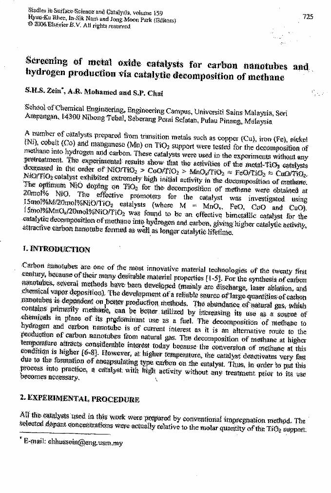
Fi.g, 1. tuet{5IafiO'tlship, between ttte -catoonAc~um:ulatipnand them:tO dt)f1ttl~()n T1Qhsu1'1,llott In thetll-ethatte·q¢¢qi:nP()S'fttonat9~$; K and 41i-rSV of27eOl(1 atsteadystafe. .
Na..O;~llPentr:atl'Qn: W$\t$itj'ed ft~rn 2;$ tp'SJ5mQtWQ onti()i?sllPpolit ,~ $h~wil') in ]fl~.L.r:~ .,. .. ";;\JmN~O d~l\lit1~ ~n. "Blf.}z fop .(l¢~~(i)$i~ton 0'£ $~lra:llte t'i~ttatneg "Wlt\S·'. -a:t20m'9I<l:, ~i1tm~t:m.c,t~as:eth~N,iQcOlttfct?it :o,t!lOO1i:~'2 $~~;pocitt lead:stt) l'QW~t:tb1~;caj;~Qna~~Utn:t\11ltiQ'n. :MinIf101;,"aca:l~$tsw-tthdiiffet'ent-lll1tQd.QptT1!g·Wi~te,ittv~t1.gatM;u,$ing~:~]'a$lfi ·te¥~ar ;thet~&'OtlQf1nwere~n;b:on~e:c:Utm:ilatiQn -''''ChIS 4jQ$~tvedQ;Vefhi;gh,.l.oa~¢d N$Q-'¢,nta,' "; Th~; .~~~., test.(~t'S(}b~~ih¢4 i;niic.at~tl1~las the',amou,P't'6f'Nt(),lQa:<t~d:Ht¢t~a'$:e<l, the:rt'iu 'Q;fMtQ'$'tt~swere alsoi:tiQr;-<is-ce:t and sinteted ttl [€inn latg¢t 'N'iO~Lfttiel$whieh leatil~}J\'(tratfil~S~d:ea~ti¥a~i()n..· .
~.31'h~,~{(e~t 01;PfZ(rm;oteton ~OJ1lol%.Ntt:)fCi().2"C~t~l){st
T~~J.e:l suowsfheperfoManceo'ftbe pt~mQted"t%ttal"st$t'orthede.¢o1U~(,)sirion()f
=519aif*~~s=::=~W:==~-~Ml<rJ::~~~~nJ.*ac:e$'.the ,slabilt1:yand thet.esl'sti\;):il-ityofthe'Nl0/TiO:z qat;xl:y.s;t·towards itiS drea~tivat10n.
fable.J
11n~~errO~~():t;fke Wtifa.~Y$:ts dypedwitJil tr~I\$'itipn tn~t~t!S '011 201Ti<¥!,% NjOt'fiOl;~~)fS~(Oit 1t-~4ttQ.~~lVPtot\tU.~rOh 11l9~~; ~ iqi'd'~$~o:t2.:Z6~'11·+ :ait s;tea~yS'ta:te;
OF
~'0'$O~){);~ii(;!lnt)21$ ,t¥:1;l\tl~ eit()tl@m(:):lP/Ii: 'N'iQiTtOj!lSm~l~rlYltl0*J4'O mgl'¥4 t4tt)tfi;02M·~'£)1'W~.tf~~2~m<:rl;<%.l'N!fQ:t12'lt;)-2J.~::m~~~;1i~Qt~Ql\r,l{):1~l'*i'Ql~tQa..
5 min." .J"
6161s.~
7ll.~6
·H;2 e<J'i1centra'ftort .(~}:.. . - - - .
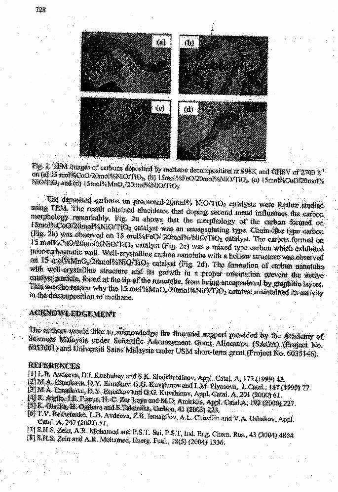
:~~~~~~~.,~a~'~~~~il~~~ar~~l1s; ~~f;r_Ql€:~..Z~~,1~lSl;IQf'CiQ2(l~~~f$ .w~t~il*,~ii~;
U$it. '~. :the tes:ult O.b:tainex,iclJfc.tl!atOi·'Ilat dt\lp:t~ s~t:idmetm it1';ftt'l~trt:l~ ,._ifiJtl .
~~E~~B~'I!~~ .. ' . ,.~.~~¥b~t';l;n:an'(t~be with,an~~l~:w :s;tme.~i\~l~~~~~'
~) ... a~~~~~~i~.t~.~~#itU:~n.:ei·meth~l;'¥(l! ..At.·_t.~~"lR..~.~m...t0.~ ._~..~--.~.\I!!l.~._&~s& __.U$M==--=~~~~••~~!li~
Ti~1:&~;AV:d~i~J:>i1KOlSh:Ufut>Y~d~.~.,8haikbutdi.l1dV"A;p~tCattal. 4,.117 {l'~it:}?l;3;.. ,..' . '.' .... 1;'¥'_.~¥':~~(o~~f~Q~~t~.iJtii¥~J~Q.\';~J.,~~!J.g,1(I~gg,t7~.
Ds~,~~Q~{~~Q'i~,'.K;\f~$h.tlv'. ",~V!;e~.A;,2f!);t~~!~t)a;61.. "d,~jf,~:i .' .'. .e.J>:~;Jl,~,t'l0,~~;~Ii.
";'''' •. ;;,> .i.,>,· '\"" ."'''. ,~··~~1.,41~~~~.;., , 'f,'':'.-.T.v:.~(),L;B.• AiVtl~'Va. ~.R. IStfuigtlt'1'\,- AJL.CbwvlbnanGtV.~. UglJa:I€~\'~AlPpl ..c:i~~~lt~!,~:I!1'{i1Q:O~j$1 •.
f7<l SiJil;g,t\~~, .;q~ed andlf?,S;T. S'a:i,ft$':r, Ind. Eil1g. Cb-el1'1.&f.%h, 4S~~4~4I04,Ei1) $..tt~i, '·.~.A~lt,M~b~mfXltE~e~8;Fuet, li8{5J'~4~ :l~~'O.;
Jnurn<lll)f NalUral Gil:> Chemistrywww.~lsevier.comllocate/jngc
Available online at www.sciencedirect.com
ScienceDirectJournal of Natural Gas Chemistry 15(2006)266~·270
Article
rilB. ~
SCIENCE PRESS
Production of High Purity Multi-Walled Carbon Nanotubesfrom Catalytic Decomposition of Methane
Kong Bee Hong,Mahayuddin,
Aidawati Azlin Binti Ismail,Abdul Rahman Mohamed,
:Mohamed Ezzaham Bin MohdSharif Hussein Sharif Zein*
School of Chemical Engineering, EngineeTing Campus, Univenili So:ins Mo,laysia,14300 Nibong Tebal,
Seberang Perai Selatan, Pv.lav. Pino,ng, Malaysia
[l\ilanllscript received October 18, 2006]
Abstract: Acid-based purification process of multi-walled carbon nanotubes (MV/NTs) produced viacatalytic decomposition of methane with NiO/Ti02 as a catalyst is described. By combining the oxidation in air and the acid refluxes, the impurities, such as amorphous carbon, carbon nanoparticles, andthe NiO/Ti02 catalyst, are eliminated. Scanning electron microscopy (SEM) and transmission electronmicroscopy (TEM) images confirm the removal of the impurities. The percentage of the carbon nanotubespurity was analyzed using thermal gravimetric analysis (TGA). Using this process, 99.9 wto/c, purity ofMWNTs was obtained.Key wOl'ds: multi-walled carbon nanotubes; !Jurification: acid refluxes: oxidation; methane: decom-position 1'",
,
I
1. Introduction
Since their discovery by Iijima in 1991 [1], carbon nanotubes have been extensively researched andhave resulted in various potential applications [2-4],thus opening a new chapter in· nanoscale materialsscience. However, a major issue that remains unresolved is its purification. Most syntl;.esis methods ofthe carbon nanotubes are based on the use of the catalyst and the as-synthesized carbon nanotubes are thencontaminated with metal catalyst and other carbonaceous materials such as amorphous carbon and carbonnanoparticles [5]. These impurities are closely entangled with the carbon nanotubes and hence influencethe carbon nanotubes structural and electronic prof;lerties and thereby limit their applications [6]. Therefore, it is necessary to purify the as-synthesized carbon nanotubes to enable their application in manyareas.
Several purification processes have been reported.
For example, \i\Tiltshire et al. [7] used magnet to separate ferromagnetic catalyst particles from an aqueoussurfactant solution of carbon nanotubes. The residual quantity of the Fe catalyst was 3 wt%. Moonet at. [8] used a two step process of thermal annealing in air and acid treatment to purify single-walledcarbon nanotubes. This process provided carbon nanotubes with metal catalysts less than 1%. Stronget at. [9] used a combination of oxidation followedby acid washing and provided residue mass as lowas 0.73 wt%. A microwave-assisted digestion systemwas used to dissolve the rnetal catalyst in organic acidfollowed by filtration [10,11]. This method provided99.9 wt% purity of the carbon nanotubes.
Although various purification methods have beenreported by researchers, which have shown high purity. no effective cornman method has yet been foundfor t.he removal of impurities for all types of assynthesized carbon nanotubes. Therefore, the purification met,hod depends on the specific type of cat-
* Corresponding author. Tel: 6045996442; Fax: 604-5941013: E-mail: [email protected]
Special Column of the INRET 2006/Joumal of Natural Gas Chemistry Vol. 15 No.4 2006 267
alyst used in the synthesis of carbon nanotubes, thereaction time, and the temperature [12].
Recently, our group had succeeded in obtaining ahigher yield in the synthesis of JvIWNTs from methanedecomposition using NiO/Ti02 as the catalyst [13]with activation energy, 60 kJ /mol: being the lowestreported in the literature for this reaction [14]. Toenable their application in rnany areas, it was necessary to purify the as-synthesized MvVNTs. In thisarticle, an acid-based purification process of the assynthesized MWNTs produced via catalytic decomposition of methane with NiO/Ti02 as the catalysthas been reported.
2. Experimental
2.1. Samples
Multi-walled carbon nanotubes (MW'NTs) weresynthesized via the catalytic decomposition ofmethane with NiO/Ti02 as the catalyst. A completedescription of the synthesis of the catalyst and the carbon nanotubes are explained in detail elsewhere [13].
2.2. Purification
...The acid-based purification process of mh~ti-
walled carbon nanotubes (MvVNTs) produced viacatalytic decomposition of methane with NiO/Ti02as the catalyst has been described. The acidrefluxes/the chemical oxidation process and the acidrefluxes/the oxidation in air process have been compared. In the first step, 0.5 g of MWNTs was refluxedin 100 ml of concentric acid (10 M) above boiling pointfor 6 h. The effectiveness of nitric acid and sulfuric acid on the impurities were alsb compared in thisstep under similar conditions. Then, the acid treated
"'"MWNTs were either oxidized in air or chemically. Ox-idation in air was done in a furnace at 350°C for2 h. Chemical oxidation was done using KMn04 andH2S04 at 80°C for 1 h. The treated MWNTs werethen separated from the chemical solutions using microfiltration. The MWNTs obtained after the oxidation process were then dispersed in an aqueous solqtion of benzalkonium chloride. The mixture was the~sonicated for 2 h and the suspension was then separated from the solution using microfiltration. Thesolid caught on the filter was then soaked in ethanolto washout the surfactant. A final washing was donewith de-ionised water and then dried in an oven oftemperature 120°C for 8 h.
2.3. Characterization
The morphology of the MvVNTs before and after the purification process were examined using thescanning electron microscope (SE?liI) system (A LeoSupra 50 VP Fuel Emission) and the transmissionelectron microscope (TE\I) system (Philips ModelClvI12). The percentages of the impurities of theMWNTs before and after the purification processwere analyzed using thermal gravimetric analysis(Perkin Elmer TGA7 Thermogravimetric Analyzer).
3. Results and discussion
Thermogravirnetric analysis (TGA) is used to detect the percentage of MWNTs, metal catalysts, andother impurities according to the combustion temperature difference between these materials. Figure 1shows the TGA and the differentiated thermogravimetric analysis (DTG) curves of lvIWNTs before andafter purification. In Figure l(a). l(h), l(c), and l(d),the ::;olid lines and the dotted lines correspond to theTGA curves and the DTG curves, respectively. Figurel(a.) shows the TGA of the as-synthesized MWNTsand indicates that the weight starts to reduce near510°C. The TvIWNTs were completely burned at700°C. The remaining materials were metal catalysts,which were approximatel:v 29%, of the entire weight.There was only one stepwise weight-loss, which indicates that the MWNTs did not contain amorphouscarbon. In the DTG curve, no peak was found in atemperature below 500°C, which again indicates thatthe MWNTs did not contain amorphous carbon. Thepeak at 620°C in the DTG curve indicates the oxidation temperature of the MWNTs. Figure 1(h) showsthe TGA re::;ult::; of TvIWNTs, which were purified using the nitric acid refluxes followed by chemical oxidation. I3ased on the TGA curve, the combustion temperature range between 0 °C and 100°C is assumed tobe water vapor. There was a small peak in the DTGcurve at temperature 200°C, which indicates the presence of 4 wt% amorphous carbon in the rv'1WNTs. TheMWNTs ::;tarted burning at 450°C and completed at650 °C. In this temperature range, the weight percent of the sample dropped from 95 wt% to 75 wt%.This shows that the sample contains only approximately 20 wt% MWNTs. This is considerably lowerthan the as-synthesized MWNTs (Figure 1 (a)). Thismaybe because the chemicals used for purification remained in the sam.ple. The initial burning temperature of "MWNT::; (450°C) is lower than that of the
268 Kong Bee Hong et aJ./ Journal of NattlraJ Ga., Chemistry Vol. 15 No.4 2006
as-synthesized MWNTs (500°C). This is because ofthe metal catalysts that still remained in the M\iVNTsand enhanced the combustion rate of the MWNTs andthus reduced the combustion temperature [15]. Figure l(c) shows the TGA graph of MWNTs that werepurified using nitric acid refluxes followed by oxidation in air. There was no weight loss between 0 °C and400°C, which indicates that these MWNTs are freeof amorphous carbon. The MWNTs started burningat approximately 500°C and completed at 700 °C.Thus, the purified MWNTs have purity of 84 wt%.The metal catalysts that still exist were of 16 wt%.Therefore, in this purification process, oxidation inair is more suitable than chemical oxidation.
To remove the end caps of the multi-walled carbonnanotubes and to expose the metal oxides for furtheracid dissolving, oxidation in air was introduced priorto acid refluxes. Figure l(d) shows the TGA graph ofthe MWNTs after purification using oxidation in airfollowed by nitric acid refluxes and then re-oxidationin air. There was no mass loss between the temperature ranges of 300°C and 400 °C, which indicatesthat the purified M\iVNTs are free of amorphous carbon. The MvVNTs started burning at 500°C andstopped at 835 °C. The residue at 835°C amountedto 8 wt% of the original mass and was attributed tothe NiO jTi0 2 catalyst. The total mass loss of this
sample wa.s 92 wt%.
0
100 -~------- -- - ..- ,-Irr- - \~ 0 100 i'l·::II.'I'i\· l'"'''':~ 100 ~/- _.- - ------.- -~-~,._-- 0
-. ,.- (~otIl'lt.'I"''qt.'t 1\. , !" -'" \" -0.5 :\',,
95' , -·10,
-20 80' ,
"
' ,"
' ,80 " C C " .::
"' ,
"'j§ -1.0] , , f'
" 90' ,
-20~"
;{!. ~ "
~ :' -40 ~ ~ 60 ", .l:' .l:' :' .l:'
§, co .l:' -1.5 .~J .l:'
C/J
, 'v 'v60 ,
"C/J 85 "
co "'v ,"
'v "'v -30 "2l= , 2l= 2l=, .!: > .!:
, -60 ;;.; .~ 40 ;;.;,
.~ ~2.0 .~>
, 80'c
, " " ""
Cl Cl -40 Cl40
jL... IL"
" -80 20" -2.5
(a) " 75 (b) , (el""
-50""\
20 \ --100 70 3.0 00 200 400 600 800 0 200 400 600 800 0 200 400 600 800
Temperature CC) Temperature CC l Temperature ( 'C l
100 ;-1,---- 0 100 f..;,- 0-~ -,- --.- .-. -~- ---~. _. -.~ 1'/'--"---_·_·'··'--·_-
"',' ,
, , , ,, -10
80, , -10 80 ,, , ,
, ' ', , c ' ' c, ' 'j§, ' -20'§, ' ' '
~, ' -20 ""0 ' ', ' ~
, ' ;{!.
~ 60 ' ' ~ 60 ' ', ' .l:' ' ', ' ' ' - 30-§J
.l:' ' 'Oil .l:' ' '
OiJ ' '.'U
C/J ' ' 'v, ' -30 " " "~
'v",
" 2l= " ", >"
-40·';40
, .~ 40, " '", .~ ">
, -40 "
'c
" " ", Cl " -50 Cl, "
20 , 20,
",
(d) ":L -50 (e) ,-60
~ '.,.,
0 -60 0 -700 200 400 600 800 0 200 400 600 800
Temperature ( 'C) Temperature eC)
Figure 1. TGA graphs of: (a) as-synthesized MWNTs, (b) MWNTs after purification using nitric acidrefluxesjchemical oxidation, (c) MWNTs aftel' purification using nitric acid refluxesjoxidation inair, (d) MWNTs after purification using oxidation in air followed by nitric acid refluxes and thenre-oxidation in air, (e) MWNTs after purification using oxidation in air followed by sulfuric acid
refluxes and then re-oxidation in air
Special Column of the INRET 2006/Journal of Natural Gas Chernistry Vol. 15 No. '1 2006 269
The effectiveness of sulfuric acid was also studied under similar conditions where TvI\VNTs were purified using oxidation in air followed by sulfuric acidrefluxes and then re-oxidation in air. This is demonstrated in Figure l(e). The first total mass loss ofthis sample was 2 wt%, which occured before 100°C.and which was probably due to water vapor. Themass loss of MWNTs started at 500°C. The residueat 850 °C amounted to 0.01 wt% of the NiO jTi02 catalyst. The purified MWNTs have purity of 99.9 wt%of the total dry original mass. Thus, sulfuric acid hashigher catalyst (NiO jTi(2) dissolving efficiency than
nitric acid.
Figure 2 (a) and (b) shmv the TE1\f and SEMirnages of the as-synthesized M\iVNTs. respectively.The metal particles were evidently embedded in thetip and between the M\VNTs. The bright spots inthe SEM image shown in Figure 2 (b) indicate themetal particles. Figure 3 (a) shows the TEM imagesof the purified !,,fWNTs. It clearly shows that alltubes were opened and the metals embedded insidethe wbes were removed. Figure 3 (b) shows that, theSEM images of the purified TvIWNTs are free of brightspots. which indicates that the purified :MWNTs arefree of metal catalysts. Hence, these results show that
the MWNTs have high purity.
Figure 2. The images of the as-synthesized MWNTs: (a) TEM, (b) SEM
Figure 3. Purified MWNTs using o'loiflation in air followed by sulfuric acid refluxes and re-oxidation in air:
(a) TEM image, (b) SEM image.
4. Conclusions
Acid refluxesjoxidation in air provides higher purification efficiency of the as-synthesized :MWN'l;'sthan acid refluxesjchemical oxidation. Oxidationin air prior to acid treatment can open the tips ofMWNTs and expose the metal particles inside thetube for further acid solvating. Oxidation in air afteracid treatment helps to remove the amorphous carbon created after the acid treatment. In this study,sulfuric acid provides a better result than nitric acid
to purify }'vIWNTs produced v-ia the catalytic decomposition of methane with NiO jTi02 as the catalyst.Using this acid, purity of T\·IWNTs as high as 99.9wt%, was obtained.
Acknowledgements
The authors acknowledge the financial support provided by Short Term Grant USM (Project: A/C No:6035146) and Academy of Sciences Malaysia under Scientific Advancement Grant Allocation (SAGA) (Project:
A/C No. 6053001).
,I
:

270 Kong Bee Hong et al./ Journal of Natnral Gas Chemistry \101. 15 No.4 2006
References
[1] Iijima C. Nature, 1991, 354: 56
[2] Dresselhaus M, Dresselhaus G, Avouris P. CarbonNanotubes: Synthesis, Properties and Application.
Berlin: Springer. 2001
[3] Baughman R H, Zakhidov A A, de Heel' W A. Science,
2002, 297: 787
[4] Zhao.1 J, Buldum A, Han .1, Lu .1 P. Nanotechnology,
2002, 13: 195
[5] Hou P X, Bai S, Yang Q H, Liu C, Cheng H M. Car
bon, 2002, 40: 81
[6] Ko C J, Lee C Y, Ko F H, Chen H L. Chu T C.Microelectron Eng, 2004, 73-74: 570
[7] Wiltshire.1 G, Li L.1, Khlobystov AN. Padbury C .1,Briggs GAD, Nicholas R J. Carbon, 2005, 43: 1151
~-
,,
[8] Moon J .:vI, An K H, Lee Y H, Park Y S. Bae D J,Park G S. J Phys Chern B, 2001, 105: 5677
[9] Strong K L, Anderson D P, Lafcli K, Kuhn J N. Car
bon, 2003, 41: 1477[10] Chen C M, Chen lVI, Leu F C, Hsu S Y, Wang S C,
Shi S C, Chen C F. Dia.mond Relat Mater, 2004, 13:
1182[11] Ko F H, Lee C Y, Ko C J, Chu T C. Carbon, 2005,
43: 727[12] Li F, Cheng H M, Xing Y T, Tan P H, Su G. Carbon,
2000, 38: 2041[13] Zein S H S, l'vlohamed A R. Energy & Faels, 2004, 18:
1336[14] Zein S H S, IVlohamed A R, Sai PST. [nd Eng Chern
Res, 2004, 43: 4864[15] Arepalli S, Nikolaev P. Gorelik 0, Hadjiev V G,
Holmes W. Files B, Yowell L. Carbon, 2004, 42: 1783
Available online at www.sciencedireet.COlll.,--"
"..;" ScienceDirectDiamond & Related Materials 16 (2007) 1517 - 1523
www.elsevier.com/locate/diamond
Study of hydrogen storage by carbonaceous material at room temperature
Nor Hasridah Abu Hassan, Abdul Rahman Mohamed, Sharif Hussein Sharif Zein *School of Chemical Engineering. Engineering Campus. Universiti Sains Malaysia. 14300 Nibong Tebal. Seberang Perai Selatan. Pulau Pinang. Malaysia
Received 6 May 2006; received in revised form 7 December 2006; accepted 14 December 2006Available online 3 JanuaIy 2007
--------_._----
Abstract
Recently, many studies have been reported about a variety of carbon materials in adsorbing hydrogen. Regarding that, hydrogen adsorption indifferent carbonaceous materials was investigated at room temperature, 298 K and three different pressures which were 6.5, 8.5 and 9.5 bar.Pressure drop ofhydrogen was measured and the amount it adsorbed was calculated by using ideal gas law and it was presented in weight percent,wt.%. In this paper, the effect ofa purification process on hydrogen adsorption was also discussed. Along with that, pretreatment also gave a majorinfluence in hydrogen adsorption because it affected the adsorption behavior of the carbon nanotubes surfaces. The highest result obtained duringthis work was 0.195 wt.% for purified carbon nanotubes.© 2006 Elsevier B.Y. All rights reserved.
Keywords: Carbonaceous material; Pretreatment; Purification process ...
1. Introduction
It is important to find an energy source that is convenient,flexible, adaptable, and controllable. Energy from the sourceshould be deliverable virtually everywhere [1]. Hydrogen isone of the renewable and environmentally friendly energysources and hydrogen storage is the· bottleneck for thebreakthrough of hydrogen as an energy cdrrier in automotiveapplications [2].
Much attention has been given to Hz stora~ materials withlight weight carbon materials, superactivated carbon [3-7],activated carbon [2,4-6], carbon nanotube [8-10], graphitenanofiber [11,12] and chemical hydrides, NaBH4 [13-15].Carbon materials have attracted a lot of interest because of theirexcellent kinetics, which is based on weak Van del' Waals forcebetween Hz and the surface of the materials. However,conflicting results have been published concerning the.reversible storage of Hz in those carbon materials [16,3-12].
In this paper, different carbon materials such as carbonnanotubes and activated carbon have been investigated in viewof their hydrogen adsorption capacity at room temperature
• Corresponding author. Tel.: +6045996442; fax: +6045941013.E-mail address:[email protected] (S.H.S. Zein).
0925-96351$ - see front matter © 2006 Elsevier B.V. All rights reserved.doi: 10. 10I6/j.diamond.2006. 12.042
(298 K). The capacities were investigated by volumetricmethod apparatus.
2. Experimental details
2.1. Material used
Five samples of unpurified carbon nanotubes, one sample ofpurified carbon nanotubes and one sample of activated carbonwere tested. Activated carbon was used as a reference materialto improve the accuracy of the experimental results. Theunpurified carbon nanotubes samples were named as CNT 1,CNT 2, CNT 3, CNT 4 and CNT 5 for the purified sample. Allthe samples were synthesized via catalytic decomposition ofmethane but with different catalysts [17,18]. Their catalyst wasclarified in Table 1.
A three-step purification process of combining oxidation inair followed by acid refluxes and re-oxidation in air has beendone on CNT 5. In the first step, 0.5 g ofcarbon nanotubes wasoxidized in a furnace at 350°C for 2 h to remove end caps ofthecarbon nanotubes and expose metal oxide for further aciddissolving. The second step of the purification process was doneby refluxing the oxidized carbon nanotubes in 100 ml ofsulfuricacid (l0 M) above boiling point for 6 h. In the third step, reoxidation in air was carried out at 350°C to remove the
1518N.H.A. Hassan et al. I Diamond & Related Materials 16 (2007) 1517-/523
Status
(1)
The principle of the volumetric method was applied by usingideal gas law. Pressure drop of hydrogen was measured and theamount it adsorbed was calculated by using ideal gas law and itwas presented in weight percent, wt.%. From the change ofpressure drop, amount of hydrogen was calculated by usingideal gas law.
Eq. (1) was used to determine the mole of hydrogenadsorbed.
PJV P2 Vn=-----.RT[ RT2
UnpurifiedUnpurifiedUnpurifiedUnpurifiedPurified
Table IClassification of carbon nallotubes
;;;-nanotubes Catalyst used in synthesizing the carbont)'Pt: nanotubes---eNT I FelNiffiOz (IM)eNT 2 NiffiOz (IM)eNT3 ColNirriOz (1M)eNT 4 NiffiOz (SO)"",T'I' 5 NirriOz (SO)\"l".::.- _--- .1M '" ImpregnatIOn.SG'" Sol Oel.
remaining water and amorphous carbons which were createdduring acid treatment from the second step.
And Eq. (2) was used to determine the weight percent ofhydrogen gas which is adsorbed in carbonaceous material.
2.2. Characterization
The morphology of the carbon nanotubes was examinedusing Transmission Electron Microscopy (TEM). In preparationfor the TEM experiments, a few samples were dispersed in100% acetone and then a drop ofeach was deposited on a coatedcopper grid. The sample then was analyzed via a TEM system(philips Model CMI2) that used an accelerating voltage of80 kV to extract electrons and Soft Imaging System model SIS3.0. The percentages of the impurities of the carbon nanotubesafter purification (CNT 5) were analyzed using thermalgravimetric analysis (perkin Elmer TGA7 ThermogravimetJjcAn~yze~. .
Pore volume and surface area measurements of the differenttypes of the synthesized carbon nanotubes were determined vianitrogen adsorption/desorption isotherms at liquid nitrogentemperature (77 K) using automated gas sorption system(Autosorp I, QuantoChrome Corporation, USA). All sampleswere degassed at a temperature of 573 K for 3 h prior to themeasurements. Computer programs (Micropore, version 2.46)allowed for rapid numerical results of the surface area and poretexture from adsorption-desorption isotherm.
Raman and Photoluminescence Spectr6scopy System(Model Jobin-Yvon HR800 UV) with wavelength of 200 nm1100 nm was used to detect the defection of carbot nanotubes.Raman spectra were collected using 514.5 nm from an argon ionlaser in the backscattering geometry and a monochromatorequipped with a peltier cooling CCD detector.
(2)
where;
Pressure in the sample chamber at time, t
Volume of sample chamberTemperature in sample chamber at time, tWeight percentage of hydrogen that is adsorbedMolecular weight of hydrogenWeight of carbon nanotubeMoles of gas that are adsorbed.
2.4. Leakage test
No real high pressure tubing can avert the leakage. It isnecessary to assess the leakage properly for the precisemeasurement because it is the major factor to get the goodand accurate result in adsorption. In this present work, for safetyreasons, leakage test was conducted in the presence of nitrogengas. To ensure that there is no leakage, the particular Valve 3 andValve 4 must be closed thoroughly before hydrogen can be sentto the chamber. Nitrogen gas was sent to the sample chamber at2 bar by passing through Valve 3 and Valve 4 and closed for 1 h.The initial value ofpressure must be recorded. This reading was
Thermocouple
Fig.!. Schematic diagram of the volumetric apparatus.
Vacuum pump I.:C::::::~.
V2 VI
l'te:sS\lresuage Pressure
t..-_~;"""'-iXl-t -,-_....p;r......,.8tlllget,
2.3. Volumetric apparatus and adsorption measurement
The adsorption measurement for all those samples wasinvestigated at room temperature at three different pressures.For adsorption measurement, 200 mg ofeach sample in powderform was filled into the sample chamber.
The tests for hydrogen adsorption were carried out in ahYdrogen storage system. It consists of heating system, samplechamber, pressure transducer, 4 needle valve, vacuum gauge,
. vacuum pump, temperature controller and thermocouple. TheSample chamber of the apparatus was made of stainless steelWith VOlume of55 x 10-6 m3 (55 ml) [19]. A schematic diagramof the VOlumetric apparatus was shown in Fig. 1.
N.H.A. Hassan et al. / Diamond & Related Materials 16 (2007) 1517-1523 1519
7060so4030Time, min
Weitht percent of HydrogCl1adsodled vs time
Fig. 3. Comparing hydrogen uptake by carbonaceous materials at 9.5 bar.
I.......Activated Carbon --CNTI-_CNT2 .......CNT3 --CNT4!
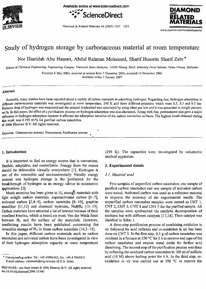
shows the best promising result in hydrogen adsorption at9.5 bar with 0.185 wt.% adsorption. The efficiency of hydrogenstorage in carbon nanostructure depends on the tube size,structure, specific surface area, microporosity and pore size ofthe nanomaterials. It was also influenced by pressure andtemperature. Thus, in this study, the pressure and the structureof the carbon nanotubes have influenced the storage capacity.
Good adsorption of hydrogen by carbon nanotubes has beenobtained at temperature of 77 K with 4.5 wt.% [21]. At 77 K,typical feature of supercritical adsorption influenced by surfacearea and pore size of the CNTs was shown. The amountadsorbed increased when the increasing pressure initiallyreached the maximum. So, pressure has a main role indetermining the storage capacity besides the other factors.However, these temperatures are not economically feasible forfuel cells.
Comparison of hydrogen uptake rate between activatedcarbon and carbon nanotubes was also conducted. It is clearlyshown that carbon nanotubes give the best result in hydrogenadsorption exceptionally for CNT 4, it may be due to thestructure of carbon nanotubes. At 298 K, the Hz adsorptioncapacity is approximately a linear function of the pressurewhich is similar to the findings of Kojima et al. This can beexplained with Henry's law which is valid for a diluted layeradsorbed on the surface. At the temperature, the interactionbased on Van der Waals force between Hz and carbon is thesame order as the thermal motion energy of Hz molecule on thesurface. In order to increase the Hz storage capacity, one shouldoperate at a much lower temperature or under high pressure[21]. As can be seen in Fig. 3, activated carbon does not storemore hydrogen than carbon nanotubes at ambient temperatureand pressure of 9.5 bar. The adsorption of activated carbon is0.05 wt.% while carbon nanotubes has 0.185 wt.% after 1 hadsorption occurs. The lower value of hydrogen adsorption byactivated carbon shows that it is very weak in this adsorptionmechanism process. It is because carbon nanotubes have latticedefects as shown in Fig. 4 and these lattice defects can adsorbmore hydrogen. Surface chemistry of carbon nanotubes is themajor factor influencing hydrogen adsorption. As a function ofpressure, temperature and local surface structure, curvature,defects and residual metal catalyst also play an important role.Moreover, hydrogen can be decomposed into atomic hydrogen,as Hz .... 2H due to the above mentioned factors, and might
.,
8040ntne.,mln
Q;07..,.----------------,
.t8t 0.1)6+----------+-----;'$,i .
tl·····.;.i.~.~~~.' "'(li03'+------...j~------_1
O,6#+-'........- ........-"':\t~,..,..----_ ................"".. O;(}]
= o()
Fig. 2. Comparing uptake of hydrogen at various pressures.
3. Result and discussion
taken by pressure gauge after V3. After 1 h of leakage testing,the pressure value must be checked. The changes in pressurevalue indicate that leaking happened in the experimentalsystem. However, ifthe pressure did not change, it is consideredthat there is no leakage in the system, and the experiment can beproceeding by sending hydrogen gas for adsorptionmeasurement.
The main objective of this work is to determine the amountof hydrogen stored in carbonaceous materials at roomtemperature. The experiment of hydrogen uptake was carriedout at three different pressures which are 6.5, 8.5, and 9.5 bar. Itwas tested on different samples of carbon nanotubes andactivated carbon at those pressures. Volumetric method wasapplied to this system in measuring the hydrogen adsorption.Pressure drop of hydrogen was measured and the amount itadsorbed was calculated by using ideal gas law and it waspresented in weight percent, wt.%.
The apparatus used for hydrogen adsorption is a typicaldevice for pressure up to lObar. However, most studiesconcerning the hydrogen storage have been carried out at highpressure (10-160 bar) and low temperature (80-133 K) in orderto store molecular hydrogen by physisorption. But, in thepresent work, a pressure of 9.5 bar and 300 K (ambientcondition) were applied to the system in adsorbing the hydrogen. The amount of Hz that can be stored in an adsorptionsystem is determined by the nature of the adsorption materialand the operating condition of the storage system [20]. ~
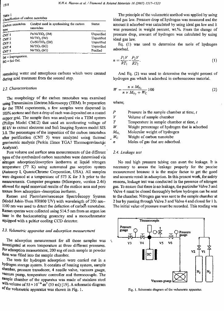
Fig. 2 shows the hydrogen uptake on carbon nanotube 1(CNT 1) at 3 different pressures. By observation, the pressure9.5 bar gives the highest hydrogen uptake rate followed by8.5 bar and 6.5 bar. In the experiment with 9.5 bar pressure,0.065 wt.% of hydrogen adsorbed after 1 h adsorption occurs.This best promising result indicates that hydrogen was adsorbedat the highest rate at 9.5 bar and it was concluded that pressurealso has a major influence in adsorbing hydrogen.
Fig. 3 shows the experiment that was conducted with onesample of activated carbon and four samplt!§ of unpurifiedcarbon nanotubes at 9.5 bar. Due to the result obtained, CNT 4
1520 NH.A. Hassan et al. / Diamond & Related Materials /6 (2007) 15/7-/523
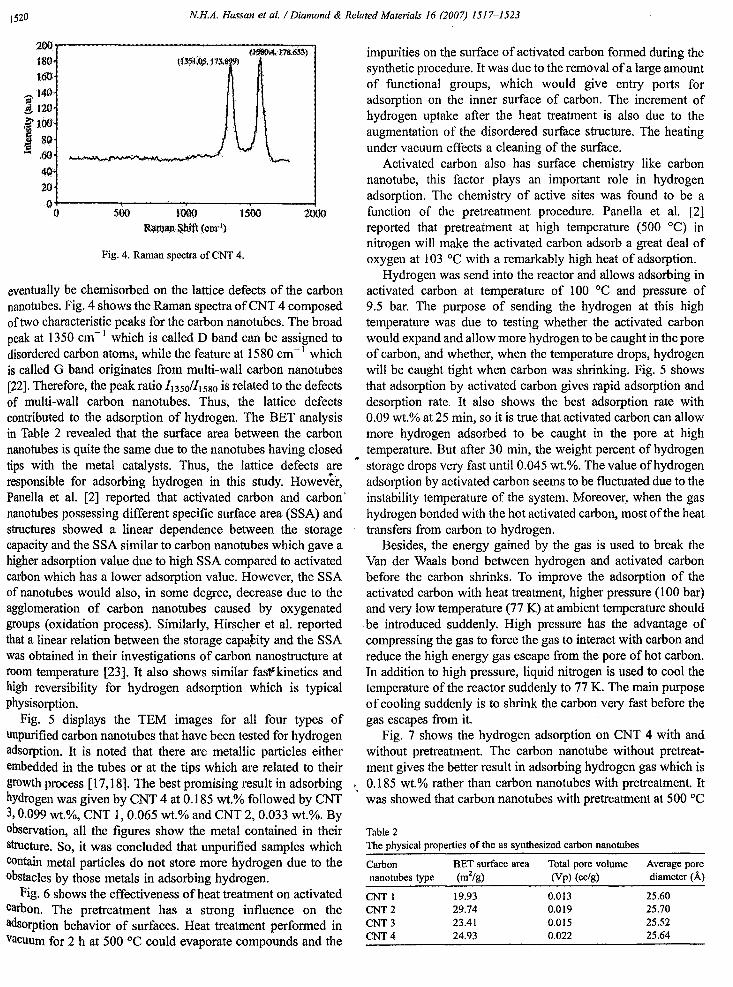
impurities on the surface of activated carbon formed during thesynthetic procedure. It was due to the removal ofa large amountof functional groups, which would give entry ports foradsorption on the inner surface of carbon. The increment ofhydrogen uptake after the heat treatment is also due to theaugmentation of the disordered surface structure. The heatingunder vacuum effects a cleaning of the surface.
Activated carbon also has surface chemistry like carbonnanotube, this factor plays an important role in hydrogenadsorption. The chemistry of active sites was found to be afunction of the pretreatment procedure. Panella et al. [2]reported that pretreatment at high temperature (500°C) innitrogen will make the activated carbon adsorb a great deal ofoxygen at 103°C with a remarkably high heat of adsorption.
Hydrogen was send into the reactor and allows adsorbing inactivated carbon at temperature of 100°C and pressure of9.5 bar. The purpose of sending the hydrogen at this hightemperature was due to testing whether the activated carbonwould expand and allow more hydrogen to be caught in the poreof carbon, and whether, when the temperature drops, hydrogenwill be caught tight when carbon was shrinking. Fig. 5 showsthat adsorption by activated carbon gives rapid adsorption anddesorption rate. It also shows the best adsorption rate with0.09 wt.% at 25 min, so it is true that activated carbon can allowmore hydrogen adsorbed to be caught in the pore at hightemperature. But after 30 min, the weight percent of hydrogenstorage drops very fast until 0.045 wt.%. The value of hydrogenadsorption by activated carbon seems to be fluctuated due to theinstability temperature of the system. Moreover, when the gashydrogen bonded with the hot activated carbon, most ofthe heattransfers from carbon to hydrogen.
Besides, the energy gained by the gas is used to break theVan der Waals bond between hydrogen and activated carbonbefore the carbon shrinks. To improve the adsorption of theactivated carbon with heat treatment, higher pressure (100 bar)and very low temperature (77 K) at ambient temperature shouldbe introduced suddenly. High pressure has the advantage ofcompressing the gas to force the gas to interact with carbon andreduce the high energy gas escape from the pore of hot carbon.In addition to high pressure, liquid nitrogen is used to cool thetemperature of the reactor suddenly to 77 K. The main purposeofcooling suddenly is to shrink the carbon very fast before thegas escapes from it.
Fig. 7 shows the hydrogen adsorption on CNT 4 with andwithout pretreatment. The carbon nanotube without pretreatment gives the better result in adsorbing hydrogen gas which is
" 0.185 wt.% rather than carbon nanotubes with pretreatment. Itwas showed that carbon nanotubes with pretreatment at 500°C
200r--------------t1-:5-:$Il--\4.-j-:1s-.6S.--a......,}
IlIO160140-;-
~120
11:.El 60
40'20O+----..---~~r------r---...-.l
o 500 UlOO 1500Ranlan&hift (qnr1)
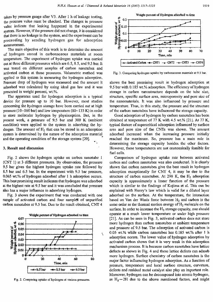
Fig. 4. Raman spectra of CNT 4.
eventually be chemisorbed on the lattice defects of the carbonnanotubes. Fig. 4 shows the Raman spectra ofCNT 4 composedof two characteristic peaks for the carbon nanotubes. The broadpeak at 1350 cm-I which is called D band can be assigned todisordered carbon atoms, while the feature at 1580 cm-I whichis called G band originates from multi-wall carbon nanotubes[22]. Therefore, the peak ratio /1350/11580 is related to the defectsof multi-wall carbon nanotubes. Thus. the lattice defectscontributed to the adsorption of hydrogen. The BET analysisin Table 2 revealed that the surface area between the carbonnanotubes is quite the same due to the nanotubes having closedtips with the metal catalysts. Thus, the lattice defects areresponsible for adsorbing hydrogen in this study. However,Panella et al. [2] reported that activated carbon and carbon'nanotubes possessing different specific surface area (SSA) andstructures showed a linear dependence between the storagecapacity and the SSA similar to carbon nanotubes which gave ahigher adsorption value due to high SSA compared to activatedcarbon which has a lower adsorption value. However, the SSAof nanotubes would also, in some degree, decrease due to theagglomeration of carbon nanotubes caused by oxygenatedgroups (oxidation process). Similarly, Hirscher et al. reportedthat a linear relation between the storage capa~ity and the SSAwas obtained in their investigations of carbon nanostructure atroom temperature [23]. It also shows similar fasfkinetics andhigh reversibility for hydrogen adsorption which is typicalphysisorption.
Fig. 5 displays the TEM images for all four types ofunpurified carbon nanotubes that have been tested for hydrogenadsorption. It is noted that there are metallic particles eitherembedded in the tubes or at the tips which are related to theirgrowth process [17,18]. The best promising result in adsorbinghydrogen was given by CNT 4 at 0.185 wt.% followed by CNT3,0.099 wt.%, CNT 1, 0.065 wt.% and CNT 2,0.033 wt.%. Byobservation, all the figures show the metal contained in theirstructure. So, it was concluded that unpurified samples whichCOntain metal particles do not store more hydrogen due to theobstacles by those metals in adsorbing hydrogen.
Fig. 6 shows the effectiveness of heat treatment on activatedcarbon. The pretreatment has a strong influence on theadsorption behavior of surfaces. Heat treatment performed inVacuum for 2 h at 500°C could evaporate compounds and the
Table 2The physical properties of the as synthesized carbon nanotubes
Carbon BET surface area Total pore volumenanotubes type (m2/g) (Vp) (cc/g)
CNT 1 19.93 0.013CNT 2 29.74 0.019CNT 3 23.41 0.015CNT 4 24.93 0.022
Average porediameter (A)
25.6025.7025.5225.64
N.H.A. Hassan et al. / Diamond & Related Materials /6 (2007) /5/7-/523 1521
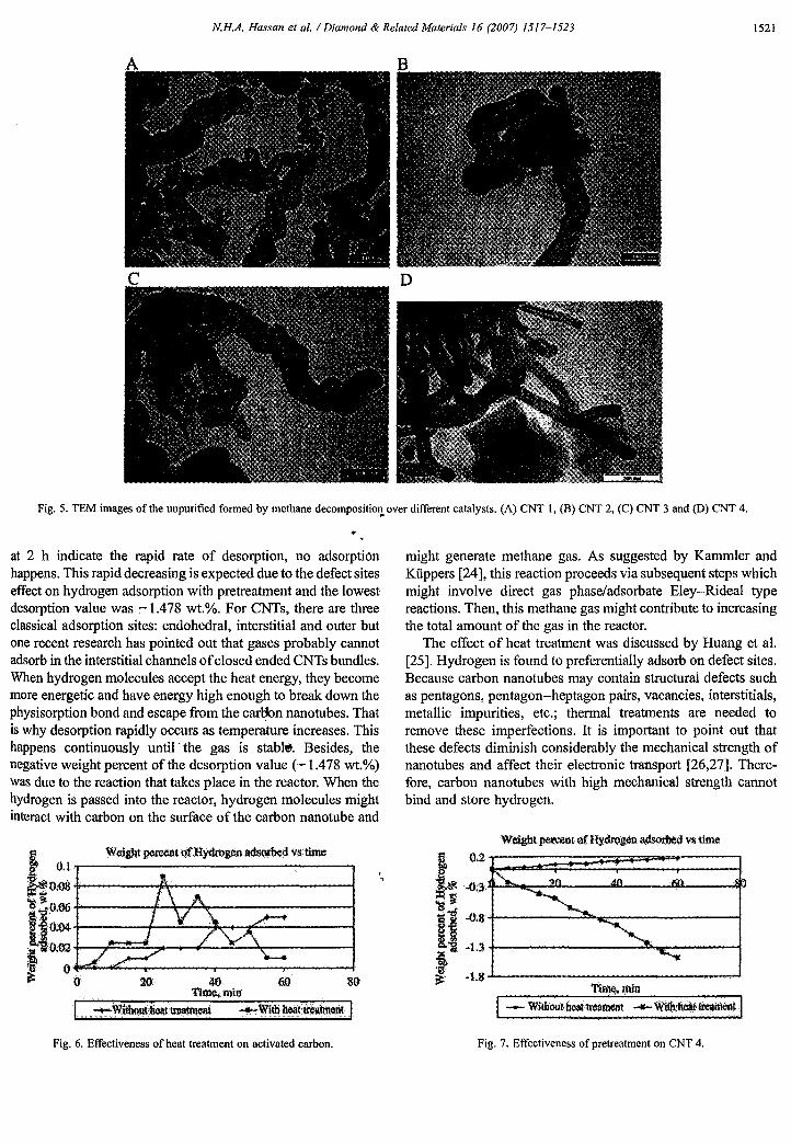
A
Fig. 5. TEM images of the unpurified formed by methane decompositiol). over different catalysts. (A) CNT 1, (B) CNT 2, (C) CNT 3 and (0) CNT 4.
at 2 h indicate the rapid rate of desorption, no adsorptionhappens. This rapid decreasing is expected due to the defect siteseffect on hydrogen adsorption with pretreatment and the lowestdesorption value was :-1.478 wt.%. For CNTs, there are threeclassical adsorption sites: endohedral, interstitial and outer butone recent research has pointed out that gases probably cannotadsorb in the interstitial channels ofclosed ended CNTs bundles.When hydrogen molecules accept the heat energy, they becomemore energetic and have energy high enough to break down thephysisorption bond and escape from the car~n nanotubes. Thatis why desorption rapidly occurs as temperature increases. Thishappens continuously until' the gas is stabl~. Besides, thenegative weight percent of the desorption value (-1.478 wt.%)was due to the reaction that takes place in the reactor. When thehydrogen is passed into the reactor, hydrogen molecules mightinteract with carbon on the surface of the carbon nanotube and
might generate methane gas. As suggested by Kammler andKiippers [24], this reaction proceeds via subsequent steps whichmight involve direct gas phase/adsorbate Eley-Rideal typereactions. Then, this methane gas might contribute to increasingthe total amount of the gas in the reactor.
The effect of heat treatment was discussed by Huang et al.[25]. Hydrogen is found to preferentially adsorb on defect sites.Because carbon nanotubes may contain structural defects suchas pentagons, pentagon-heptagon pairs, vacancies, interstitials,metallic impurities, etc.; thermal treatments are needed toremove these imperfections. It is important to point out thatthese defects diminish considerably the mechanical strength ofnanotubes and affect their electronic transport [26,27]. Therefore, carbon nanotubes with high mechanical strength cannotbind and store hydrogen.
.,
20 40 60 80Time. mil)
I Weigbt p¢rC¢JltQfHydrogeo lUisofbed vnime
l~o:~.,.-------------:-----,::: ....
i.·i".:+----+-----:--';;;.-~~-----;i to;~..,.::....."'"""-----....----..----...+~ 0
Fig. 6. Effectiveness of heat treatment on activated carbon. Fig. 7. Effectiveness of pretreatment on CNT 4.
1522 N.H.A. Hassan et al. / Diamond & Related Materials 16 (2007) ]517-1523
Weight pen:ent OfHydrogenadsoJ;bedv$ time
10 20 30 II{) SO 60 70Time, min
~11ii1putifled ....... lfurified• -,. "U
! 0.25
§ ,(:);~+---------~__--1i'~~. '~OJ5+--------=~=------l
I,t 0.1~~ 0.05 +--"""':J'l'F'-----------l
·f 0 ....=-,--.,.---r--,--,---.----ll!$: 0
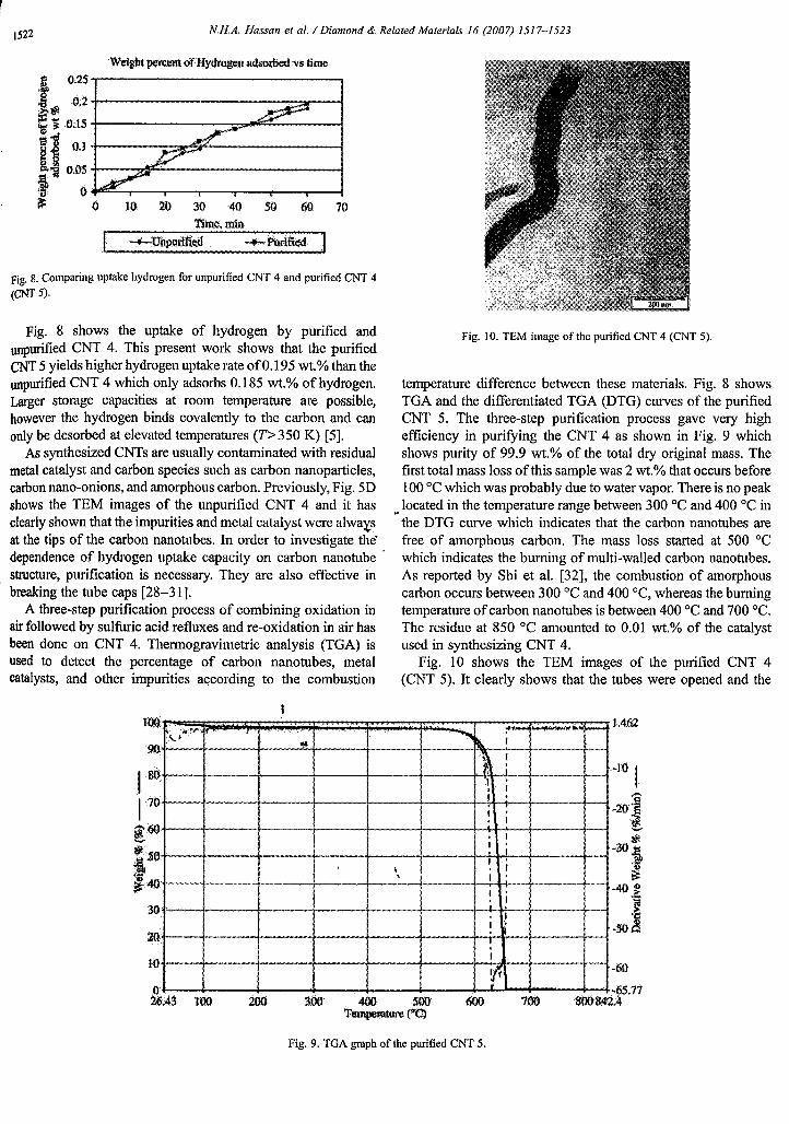
Fig. 8. Comparing uptake hydrogen for unpurified CNT 4 and purified CNT 4
(CNT 5).
Fig. 8 shows the uptake of hydrogen by purified andunpurified CNT 4. This present work shows that the purifiedCNT 5 yields higher hydrogen uptake rate of0.195 wt.% than theunpurified CNT 4 which only adsorbs 0.185 wt.% of hydrogen.Larger storage capacities at room temperature are possible,however the hydrogen binds covalently to the carbon and canonly be dcsorbed at elevated temperatures (T>350 K) [5].
As synthesized CNTs are usually contaminated with residualmetal catalyst and carbon species such as carbon nanoparticles,carbon nano-onions, and amorphous carbon. Previously, Fig. 5Dshows the TEM images of the unpurified CNT 4 and it hasclearly shown that the impurities and metal catalyst were alwa>;.sat the tips of the carbon nanotubes. In order to investigate the'dependence of hydrogen uptake capacity on carbon nanotube .structure, purification is necessary. They are also effective inbreaking the tube caps [28-31].
A three-step purification process of combining oxidation inair followed by sulfuric acid refluxes and re-oxidation in air hasbeen done on CNT 4. Thermogravimetric analysis (TGA) isused to detect the percentage of carbon nanotubes, metalcatalysts, and other impurities according to the combustion
Fig. 10. TEM image of the purified CNT 4 (CNT 5).
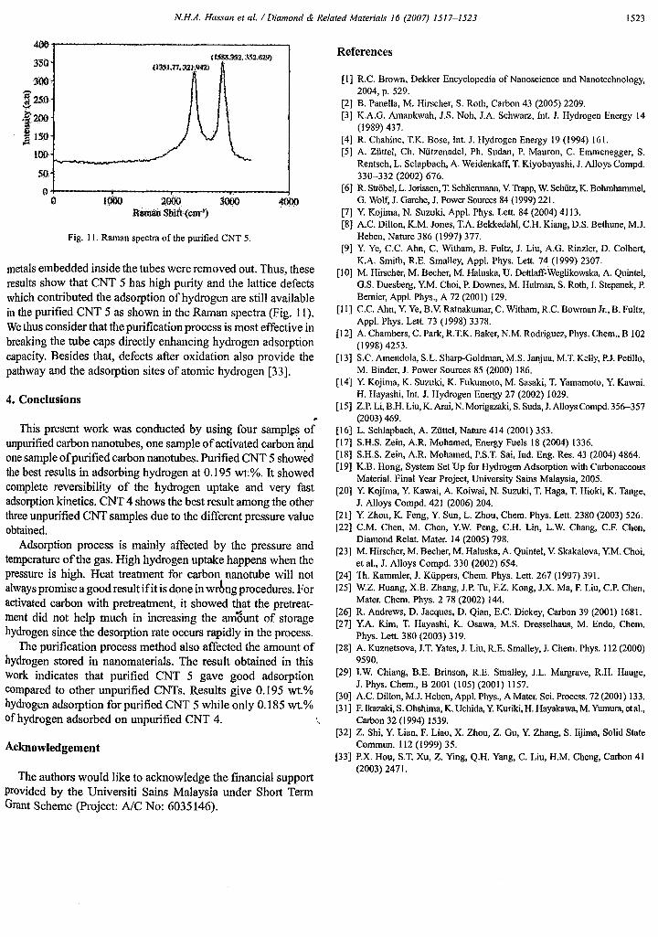
temperature difference between these materials. Fig. 8 showsTGA and the differentiated TGA (DTG) curves of the purifiedCNT 5. The three-step purification process gave very highefficiency in purifYing the CNT 4 as shown in Fig. 9 whichshows purity of 99.9 wt.% of the total dry original mass. Thefirst total mass loss of this sample was 2 wt.% that occurs before100°C which was probably due to water vapor. There is no peak
~ located in the temperature range between 300°C and 400 °C inthe DTG curve which indicates that the carbon nanotubes arefree of amorphous carbon. The mass loss started at 500°Cwhich indicates the burning of multi-walled carbon nanotubes.As reported by Shi et al. [32], the combustion of amorphouscarbon occurs between 300°C and 400 °C, whereas the burningtemperature ofcarbon nanotubes is between 400°C and 700 0c.The residue at 850°C amounted to 0.01 wt.% of the catalystused in synthesizing CNT 4.
Fig. 10 shows the TEM images of the purified CNT 4(CNT 5). It clearly shows that the tubes were opened and the
_._-
Fig. 9. TGA graph of the purified CNT 5.
:I1: ~--~..._-+----+._----~--_. __._+-._..._- tl----"-· ::.77
26.43 100 200 300' 400 500 600 100 800842'.4'l"emper:ature("Cl
N.H.A. Hassan et al. / Diamond & Related Materials 16 (2007) /5/7-/523
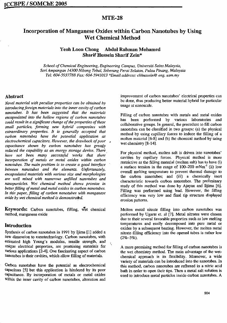
Fig. II. Raman spectra of the purified CNT 5.
1523
References
[I] RC. Brown, Dekker Encyclopedia ofNanoscience and Nanotechnology,2004, p. 529.
[2] B. Panella, M. Hirscher, S. Roth, Carbon 43 (2005) 2209.[3] KA.G. Amankwah, J.S. Noh, J.A Schwarz, Int. 1. Hydrogen Energy 14
(1989) 437.[4] R. Chahine, T.K. Bose, Int. J. Hydrogen Energy 19 (1994) 161.[5] A. Ziittel, Ch. Niitzenadel, Ph. Sudan, P. Mauron, C. Emmenegger, S.
Rentsch, L. Sclapbach, A. Weidenkaff, T. Kiyobayashi, J. Alloys Compd.330-332 (2002) 676.
[6] R Strobel, L. Jorissen, T. Schlienuann, V. Trapp, W Schiitz, K. Boluuhammel,G. Wolf, J. Garche, J. Power Sources 84 (1999) 221.
[7] Y. Kojima, N. Suzuki, Appl. Phys. Lett. 84 (2004) 4113.[8] A.C. Dillon, KM. Jones, T.A. Bekkedahl, C.H. Kiang, D.S. Bethune, M.J.
Heben, Nature 386 (1997) 377.[9] Y. Ye, C.C. Ahn, C. Witham, B. Fullz, J. Liu, A.G. Rinzler, D. Colbert,
K.A. Smith, R.E. Smalley, Appl. Phys. Lett. 74 (1999) 2307.[10] M. Hirscher, M. Becher, M. Haluska, U. Dettlaff-Weglikowska, A Quintel,
G.S. Duesberg, Y.M. Choi, P. Downes, M. Hulman, S. Roth, 1. Stepanek, P.Bernier, Appl. Phys., A 72 (2001) 129.
[II] C.C. Ahu, Y. Ye, B.V. Ratnakumar, C. Witham, RC. Bowman Jr., B. Fultz,Appl. Phys. Lett. 73 (1998) 3378.
[12] A. Chambers, C. Park, R.T.K Baker, N.M. Rodriguez, Phys. Chern., B 102(1998) 4253.
[13] S.C. Amendola, S.L. Sharp-Goldman, M.S. Janjua, M.T. Kelly, P.J. Petillo,M. Binder, J. Power Sources 85 (2000) 186.
[14] Y. Kojima, K. Suzuki, K. Fukumoto, M. Sasaki, T. Yamamoto, Y. Kawai,H. Hayashi, Int. 1. Hydrogen Energy 27 (2002) 1029.
[15] Z.P. Li, B.H. Liu, K. Arai, N. Morigazaki, S. Suda, J. Alloys Compd. 356-·357(2003) 469.
[16] L. Schlapbach, A. Ziittel, Nature 414 (2001) 353.[17] S.H.S. Zein, AR Mohamed, Energy Fuels 18 (2004) 1336.[18] S.H.S. Zein, A.R. Mohamed, P.S.T. Sai, Ind. Eng. Res. 43 (2004) 4864.[19] KB. Hong, System Set Up for Hydrogen Adsorption with Carbonaceous
Material. Final Year Project, University Sains Malaysia, 2005.[20] Y. Kojima, Y. Kawai, A. Koiwai, N. Suzuki, T. Haga, T. Hioki, K. Tange,
J. Alloys Compd. 421 (2006) 204.[21] Y. Zhou, K Feng, Y. Sun, L. Zhou, Chern. Phys. Lett. 2380 (2003) 526.[22] C.M. Chen, M. Chen, Y.W Peng, C.H. Lin, L.W. Chang, C.F. Chen,
Diamond Relat. Mater. 14 (2005) 798.[23] M. Hirscher, M. Becher, M. Haluska, A. Quintel, V. Skakalova, Y.M. Choi,
et aI., J. Alloys Compd. 330 (2002) 654.[24] Th. Kammler, J. Kiippers, Chern. Phys. Lett. 267 (1997) 391.[25] WZ. Huang, XB. Zhang, J.P. Tu, F.Z. Kong, J.X. Ma, F. Lin, C.P. Chen,
Mater. Chern. Phys. 2 78 (2002) 144.[26] R. Andrews, D. Jacques, D. Qian, E.C. Dickey, Carbon 39 (2001) 1681.[27] Y.A. Kim, T. Hayashi, K Osawa, M.S. Dresselhans, M. Endo, Chern.
Phys. Lett. 380 (2003) 319.[28] A. Knznetsova, J.T. Yates, J. Liu, R.E. Smalley, J. Chern. Phys. 112 (2000)
9590.[29] I.w. Chiang, RE. Brinson, R.E. Smalley, J.1. Margrave, R.H. Hauge,
J. Phys. Chern., B 2001 (105) (2001) 1157.[30] A.C. Dillon, M.J. Heben, AppJ. Phys., A Mater. Sci. Process. 72 (2001) 133.[31] F. Ikazaki, S. Ohshima, K. Uchida, Y. Kuriki, H. Hayakawa, M. Yumura, etaJ.,
Carbon 32 (1994) 1539.[32] Z. Shi, Y. Lian, F. Liao, X. Zhou, Z. Gn, Y. Zhang, S. Iijima, Solid State
Commlm. 112 (1999) 35.[33] p.x. Hon, S.T. Xu, Z. Ying, Q.H. Yang, C. Liu, H.M. Cheng, Carbon 41
(2003) 2471.
.,
4000
(ISll8,;352. 352.~29)(I3SI.71.':\2l"J42)
4OO-r----------------,3SG
300
~2S0'V"
-1 200! ISO
100 J"-v--,....,.,...... ........--50
0+'---..,......---...------.----1o moo ~OOO 3000
RtunlinShift(crtrl)
4. Conclusions
Acknowledgement
metals embedded inside the tubes were removed out. Thus, theseresults show that CNT 5 has high purity and the lattice defectswhich contributed the adsorption of hydrogen are still availablein the purified CNT 5 as shown in the Raman spectra (Fig. 11).We thus consider that the purification process is most effective inbreaking the tube caps directly enhancing hydrogen adsorptioncapacity. Besides that, defects ,after oxidation also provide thepathway and the adsorption sites of atomic hydrogen [33].
This present work was conducted by using four sampl~s ofunpurified carbon nanotubes, one sample ofactivated carbon andone sample ofpurified carbon nanotubes. Purified CNT 5 show~dthe best results in adsorbing hydrogen at 0.195 wt.%. It showedcomplete reversibility of the hydrogen uptake and very fastadsorption kinetics. CNT 4 shows the best result among the otherthree unpurified CNT samples due to the different pressure valueobtained.
Adsorption process is mainly affected by the pressure andtemperature ofthe gas. High hydrogen uptake happens when thepressure is high. Heat treatment for carbon nanotube will notalways promise a good result ifit is done in wrbng procedures. Foractivated carbon with pretreatment, it showed that the pretreatment did not help much in increasing the am'gunt of storagehydrogen since the desorption rate occurs rapidly in the process.
The purification process method also affected the amount ofhydrogen stored in nanomaterials. The result obtained in thiswork indicates that purified CNT 5 gave good adsorptioncompared to other unpurified CNTs. Results give 0.195 wt.%hydrogen adsorption for purified CNT 5 while only 0.185 wt.%of hydrogen adsorbed on unpurified CNT 4.
The authors would like to acknowledge the financial supportprovided by the Universiti Sains Malaysia under Short TermGrant Scheme (Project: NC No: 6035146).
ICCBPE / SOMChE 2005--MTE-28
Incorporation of Manganese Oxides within Carbon Nanotubes by UsingWet Chemical Method
Yeoh Loon Chong Abdul Rahman MohamedSharif Hussein Sharif Zein*
School ofChemical Engineering, Engineering Campus, Universiti Sains Malaysia,Seri Ampangan 14300 Nibong Tebal, Seberang Perai Selatan, Pulau Pinang, Malaysia
Tel: 604-5937788 Fax: 604-5941013 *Email address: chhussein@ eng. usm.my
AbstractNovel material with peculiar properties can be obtained byintroducing foreign materials into the inner cavity ofcarbonnanotubes. It has been suggested that the materialsencapsulated into the hollow regions of carbon nanotubescould result in a significant change ofthe properties ofthesesmall particles, forming new hybrid composites withextraordinary properties. It is generally accepted thatcarbon nanotubes have the potential application aselectrochemical capacitors. However, the drawback ofpoor po
capacitance shown by carbon nanotubes has greal1yreduced the capability as an energy storage device. Therehave not been many successful works that showincorporation of metals or metal oxides within carbonnanotubes. The main problem is to create a good inteifacebetween nanotubes and the elements. Unfortunately,encapsulated materials with various size and morphologiesare well mixed with numerous unfilled nanotubes andnanoparticles. Wet chemical method shows promise inbetterfilling ofmetal and metal oxides in carbon nanotubes.In this paper, filling of carbon nanotubes with manganeseoxide by wet chemical method is demonstra~d.
improvement of carbon nanotubes' electrical properties canbe done, thus producing better material hybrid for particularusage at nanoscale.
Filling of carbon nanotubes with metals and metal oxideshas been performed by various laboratories andcollaborative groups. In general, the procedure to fill carbonnanotubes can be classified in two groups: (a) the physicalmethod by using capillary forces to induce the filling of amolten material [6-8] and (b) the chemical method by usingwet chemistry [8-14].
For physical method, molten salt is driven into nanotubes'cavities by capillary forces. Physical method is morerestrictive as the filling material (molten salt) has to have (i)a surface tension in the range of 100-200 mNm- t (ii) lowoverall melting temperature to prevent thermal damage tothe carbon nanotubes; and (iii) a chemically inertcharacteristic towards carbon nanotubes. The preliminarystudy of this method was done by Ajayan and Iijima [6].Filling was performed using lead. However, the fillingefficiency was very low and final tip structure displayederosion patterns.
Keywords: Carbon nanotubes, filling, w""et chemicalmethod, manganese oxide
IntroductionSynthesis of carbon nanotubes in 1991 by Ijima [1] added anew dimension to nanotechnology. Carbon nanotubes, withestimated high Young's modulus, tensile strength, andunique electrical properties, are promising materials forvarious applications [2-4]. One fascinating aspect of carbonnanotubes is their cavities, which allow filling of materials.
Carbon nanotubes have the potential as electrochemicalcapacitors [5] but this application is hindered by its poorcapacitance. By incorporation of metals or metal oxidesWithin the inner cavity of carbon nanotubes, alteration and
,,
Molten metal nitrate filling into carbon nanotubes wasperformed by Ugarte et. al [7]. Metal nitrates were chosendue to their several favorable properties such as low meltingtemperatures and easily decomposed into pure metal oroxides by a subsequent heating. However, the molten metalnitrate filling efficiency into the opened tubes is rather low(2%-3%).
A more promising method for filling of carbon nanotubes isthe wet chemistry method. The main advantage of the wetchemical approach is its flexibility. Moreover, a widevariety of materials can be introduced into the nanotubes. Inthis method, carbon nanotubes are refluxed in a nitric acidbath in order to open their tips. Then a metal salt solution isused to introduce metal particles inside carbon nanotubes. A
904
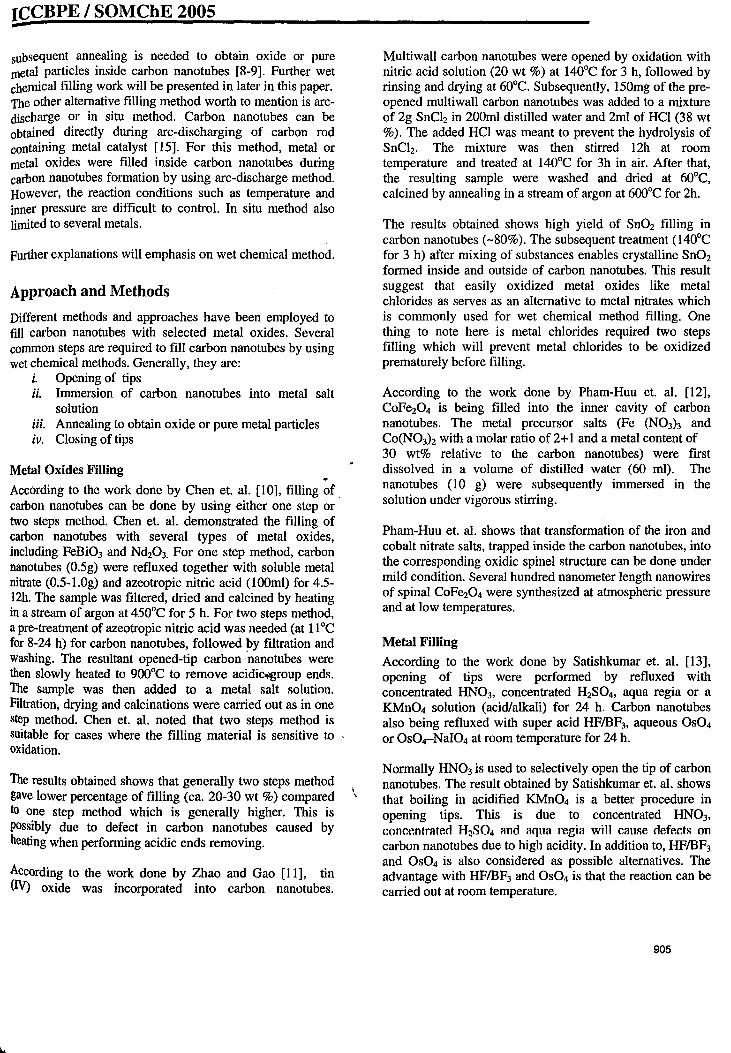
ICCBPE I SOMChE 2005-subsequent annealing is needed to obtain oxide or puremetal particles inside carbon nanotubes [8-9]. Further wetchemical filling work will be presented in later in this paper.The other alternative filling method worth to mention is arcdischarge or in situ method. Carbon nanotubes can beobtained directly during arc-discharging of carbon rodcontaining metal catalyst [15]. For this method, metal ormetal oxides were filled inside carbon nanotubes duringcarbon nanotubes formation by using arc-discharge method.However, the reaction conditions such as temperature andinner pressure are difficult to control. In situ method alsolimited to several metals.
Further explanations will emphasis on wet chemical method.
Approach and Methods
Different methods and approaches have been employed tofill carbon nanotubes with selected metal oxides. Severalcommon steps are required to fill carbon nanotubes by usingwet chemical methods. Generally, they are:
i. Opening of tipsii. Immersion of carbon nanotubes into metal salt
solutioniii. Annealing to obtain oxide or pure metal particlesiv. Closing of tips
Metal Oxides Filling 'P
According to the work done by Chen et. al. [10], filling of.carbon nanotubes can be done by using either one step ortwo steps method. Chen et. al. demonstrated the filling ofcarbon nanotubes with several types of metal oxides,including FeBi03 and Nd20 3. For one step method, carbonnanotubes (0.5g) were refluxed together with soluble metalnitrate (0.5-1.0g) and azeotropic nitric acid (1ooml) for 4.512h. The sample was filtered, dried and calcined by heatingin a stream of argon at 450°C for 5 h. For two steps method,a pre-treatment of azeotropic nitric acid was needed (at 11°Cfor 8-24 h) for carbon nanotubes, followed by filtration andwashing. The resultant opened-tip carbon'nanotubes werethen slowly heated to 900°C to remove acidic'ilgroup ends.The sample was then added to a metal salt solution.Filtration, drying and calcinations were carried out as in onestep method. Chen et. al. noted that two steps method issuitable for cases where the filling material is sensitive tooxidation.
The results obtained shows that generally two steps methodgave lower percentage of filling (ca. 20-30 wt %) comparedto one step method which is generally higher. This ispossibly due to defect in carbon nanotubes caused byheating when performing acidic ends removing.
According to the work done by Zhao and Gao [11], tin(IV) oxide was incorporated into carbon nanotubes.
I,
Multiwall carbon nanotubes were opened by oxidation withnitric acid solution (20 wt %) at 140°C for 3 h, followed byrinsing and drying at 60°C. Subsequently, 150mg of the preopened multiwall carbon nanotubes was added to a mixtureof 2g SnCh in 200ml distilled water and 2ml of HCI (38 wt%). The added HCI was meant to prevent the hydrolysis ofSnCh. The mixture was then stirred 12h at roomtemperature and treated at 140°C for 3h in air. After that,the resulting sample were washed and dried at 60°C,calcined by annealing in a stream of argon at 600°C for 2h.
The results obtained shows high yield of Sn02 filling incarbon nanotubes (-80%). The subsequent treatment (140°Cfor 3 h) after mixing of substances enables crystalline Sn02formed inside and outside of carbon nanotubes. This resultsuggest that easily oxidized metal oxides like metalchlorides as serves as an alternative to metal nitrates whichis commonly used for wet chemical method filling. Onething to note here is metal chlorides required two stepsfilling which will prevent metal chlorides to be oxidizedprematurely before filling.
According to the work done by Pham-Huu et. al. [12],CoFeZ04 is being filled into the inner cavity of carbonnanotubes. The metal precursor salts (Fe (N03)3 andCo(N03h with a molar ratio of 2+1 and a metal content of30 wt% relative to the carbon nanotubes) were firstdissolved in a volume of distilled water (60 ml). Thenanotubes (10 g) were subsequently immersed in thesolution under vigorous stirring.
Pham-Huu et. al. shows that transformation of the iron andcobalt nitrate salts, trapped inside the carbon nanotubes, intothe corresponding oxidic spinel structure can be done undermild condition. Several hundred nanometer length nanowiresof spinal CoFeZ04 were synthesized at atmospheric pressureand at low temperatures.
Metal Filling
According to the work done by Satishkumar et. al. [13],opening of tips were performed by refluxed withconcentrated HN03, concentrated H2S04, aqua regia or aKMn04 solution (acid/alkali) for 24 h. Carbon nanotubesalso being refluxed with super acid HFIBF3, aqueous OS04or Os04-NaI04 at room temperature for 24 h.
Normally HN03 is used to selectively open the tip of carbonnanotubes. The result obtained by Satishkumar et. al. showsthat boiling in acidified KMn04 is a better procedure inopening tips. This is due to concentrated HN03,
concentrated H2S04 lind aquil regill will Cllllse ciefects oncarbon nanotubes due to high acidity. In addition to, HFIBF3
and OS04 is also considered as possible alternatives. Theadvantage with HFIBF3 and OS04 is that the reaction can becarried out at room temperature.
905
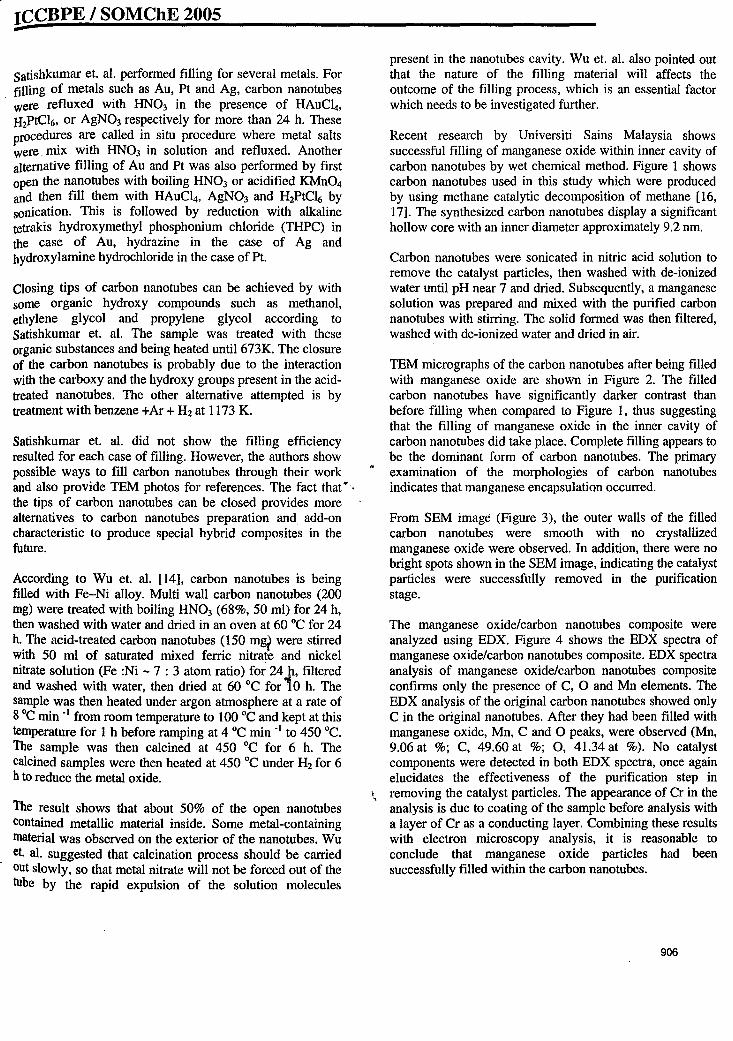
ICCBPE I SOMChE 2005
Satishkumar et. al. performed filling for several metals. Forfilling of metals such as Au, Pt and Ag, carbon nanotubeswere refluxed with HN03 in the presence of HAuCI4,lI2PtC16, or AgN03 respectively for more than 24 h. Theseprocedures are called in situ procedure where metal saltswere. mix with HN03 in solution and refluxed. Anotheralternative filling of Au and Pt was also performed by firstopen the nanotubes with boiling HN03 or acidified KMn04and then fill them with HAuCI4, AgN03 and H2PtCl6 bysonication. This is followed by reduction with alkalinetetrakis hydroxymethyl phosphonium chloride (THPC) inthe case of Au, hydrazine in the case of Ag andhydroxylamine hydrochloride in the case of Pt.
Closing tips of carbon nanotubes can be achieved by withsome organic hydroxy compounds such as methanol,ethylene glycol and propylene glycol according toSatishkumar et. al. The sample was treated with theseorganic substances and being heated until 673K. The closureof the carbon nanotubes is probably due to the interactionwith the carboxy and the hydroxy groups present in the acidtreated nanotubes. The other alternative attempted is bytreatment with benzene +Ar + H2 at 1173 K.
Satishkumar et. al. did not show the filling efficiencyresulted for each case of filling. However, the authors showpossible ways to fill carbon nanotubes through their workand also provide TEM photos for references. The fact that 'Po
the tips of carbon nanotubes can be closed provides morealternatives to carbon nanotubes preparation and add-oncharacteristic to produce special hybrid composites in thefuture.
According to Wu et. al. [14], carbon nanotubes is beingfilled with Fe-Ni alloy. Multi wall carbon nanotubes (200mg) were treated with boiling HN03 (68%, 50 ml) for 24 h,then washed with water and dried in an oven at 60°C for 24h. The acid-treated carbon nanotubes (150 mg? were stirredwith 50 ml of saturated mixed ferric nitrate and nickelnitrate solution (Fe :Ni - 7 : 3 atom ratio) for 24h, filteredand washed with water, then dried at 60°C for 10 h. Thesample was then heated under argon atmosphere at a rate of8°C min -1 from room temperature to 100°C and kept at thistemperature for 1 h before ramping at 4 °C min -1 to 450°C.The sample was then calcined at 450 °C for 6 h. Thecalcined samples were then heated at 450°C under H2 for 6h to reduce the metal oxide.
The result shows that about 50% of the open nanotubescontained metallic material inside. Some metal-containingmaterial was observed on the exterior of the nanotubes. Wuet. al. suggested that calcination process should be carriedout slOWly, so that metal nitrate will not be forced out of thetube by the rapid expulsion of the solution molecules
present in the nanotubes cavity. Wu et. al. also pointed outthat the nature of the filling material will affects theoutcome of the filling process, which is an essential factorwhich needs to be investigated further.
Recent research by Universiti Sains Malaysia showssuccessful filling of manganese oxide within inner cavity ofcarbon nanotubes by wet chemical method. Figure 1 showscarbon nanotubes used in this study which were producedby using methane catalytic decomposition of methane [16,17]. The synthesized carbon nanotubes display a significanthollow core with an inner diameter approximately 9.2 nm.
Carbon nanotubes were sonicated in nitric acid solution toremove the catalyst particles, then washed with de-ionizedwater until pH near 7 and dried. Subsequently, a manganesesolution was prepared and mixed with the purified carbonnanotubes with stirring. The solid formed was then filtered,washed with de-ionized water and dried in air.
TEM micrographs of the carbon nanotubes after being filledwith manganese oxide are shown in Figure 2. The filledcarbon nanotubes have significantly darker contrast thanbefore filling when compared to Figure 1, thus suggestingthat the filling of manganese oxide in the inner cavity ofcarbon nanotubes did take place. Complete filling appears tobe the dominant form of carbon nanotubes. The primaryexamination of the morphologies of carbon nanotubesindicates that manganese encapsulation occurred.
From SEM image (Figure 3), the outer walls of the filledcarbon nanotubes were smooth with no crystallizedmanganese oxide were observed. In addition, there were nobright spots shown in the SEM image, indicating the catalystparticles were successfully removed in the purificationstage.
The manganese oxide/carbon nanotubes composite wereanalyzed using EDX. Figure 4 shows the EDX spectra ofmanganese oxide/carbon nanotubes composite. EDX spectraanalysis of manganese oxide/carbon nanotubes compositeconfirms only the presence of C, ° and Mn elements. TheEDX analysis of the original carbon nanotubes showed onlyC in the original nanotubes. After they had been filled withmanganese oxide, Mn, C and °peaks, were observed (Mn,9.06 at %; C, 49.60 at %; 0, 41.34 at %). No catalystcomponents were detected in both EDX spectra, once againelucidates the effectiveness of the purification step in
" removing the catalyst particles. The appearance of Cr in theanalysis is due to coating of the sample before analysis witha layer of Cr as a conducting layer. Combining these resultswith electron microscopy analysis, it is reasonable toconclude that manganese oxide particles had beensuccessfully filled within the carbon nanotubes.
906
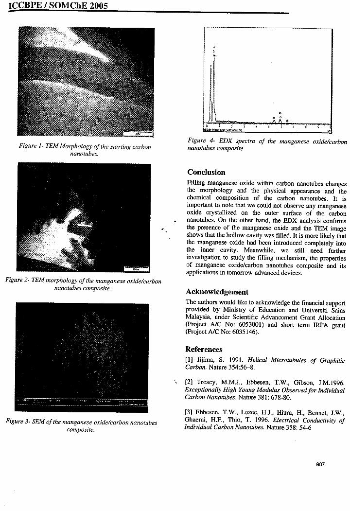
ICCBPE I SOMChE 2005-
Figure 4- EDX spectra of the manganese oxide/carbonnanotubes composite
!I'! !I i
I II. I.',I .
i ; t
..
..II <
I
Figure 1- TEM Morphology ofthe starting carbonnanotubes.
Figure 2- TEM morphology ofthe manganese oxidelcarbonnanotubes composite.
Figure 3- SEM ofthe manganese oxide/carbon nanotubescomposite.
I,
ConclusionFilling manganese oxide within carbon nanotubes changesthe morphology and the physical appearance and thechemical composition of the carbon nanotubes. It isimportant to note that we could not observe any manganeseoxide crystallized on the outer surface of the carbonnanotubes. On the other hand, the EDX analysis confirmsthe presence of the manganese oxide and the TEM imageshows that the hollow cavity was filled. It is more likely thatthe manganese oxide had been introduced completely intothe inner cavity. Meanwhile, we still need furtherinvestigation to study the filling mechanism, the propertiesof manganese oxide/carbon nanotubes composite and itsapplications in tomorrow-advanced devices.
AcknowledgementThe authors would like to acknowledge the financial supportprovided by Ministry of Education and Universiti SainsMalaysia, under Scientific Advancement Grant Allocation(Project NC No: 6053(01) and short term IRPA grant(Project NC No: 6035146).
References[1] Iijima, S. 1991. Helical Microtubules of GraphiticCarbon. Nature 354:56-8.
[2] Treacy, M.M.J., Ebbesen, T.W., Gibson, J.M.1996.Exceptionally High Young Modulus Observedfor IndividualCarbon Nanotubes. Nature 381: 678-80.
[3] Ebbesen, T.W., Lezec, H.J., Hiura, H., Bennet, J.W.,Ghaemi, RP., Thio, T. 1996. Electrical Conductivity ofIndividual Carbon Nanotubes. Nature 358: 54-6
907
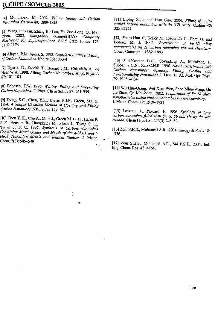
ICCBPE I SOMChE 2005-
,f
I~.
[4] Monthioux, M. 2002. Filling Single-wall CarbonNanotubes. Carbon 40: 1809-1823
[5] Wang Gui-Xin, Zhang Bo-Lan, Yu Zuo-Long, Qu MeiZhen. 2005. Manganese OxidelMWNTs CompositeElectrodes for Supercapacitors. Solid State lonies 176:1169-1174
[6] Ajayan, P.M. lijirna, S. 1993. Capillarity-induced FillingofCarbon Nanotubes. Nature 361: 333-4
[7] Ugarte, D., StOckli T., Bonard 1.M., Chatelain A, deReer W.A. 1998. Filling Carbon Nanotubes. Appl. Phys. A67: 101-105
[8] Ebbesen, T.W. 1996. Wetting, Filling and DecoratingCarbon Nanotubes. J. Phys. Chern Solids 57: 951-955.
[9] Tsang, S.C., Chen, Y.K, Harris, P.J.F., Green, M.L.H.1994. A Simple Chemical Method of Opening and FillingCarbon Nanotubes. Nature 372: 159-62.
[10] Chen Y. K, Chu A, Cook J., Green M. L. H., Harris P.1. F., Heesorn R, Humphries M., Sloan J., Tsang S. C.,Turner J. F. C. 1997. Synthesis of Carbon NanotubesContaining Metal Oxides and Metals of the d-block and fblock Transition Metals and Related Studies. J. Mater.Chern. 7(3): 545-549
,,
[11] Liping Zhao and Lian Gao. 2004. Filling if multiwalled carbon nanotubes with tin (IV) oxide. Carbon 42:3251-3272
[12] Pharn-Huu C, Keller N., Estoumes C., Ehret G. andLedoux M. 1. 2002. Preparation of Fe-Ni alloynanoparticles inside carbon nanotubes via wet chemistry.Chern. Cornrnun. : 1882-1883
[13] Satishkurnar B.c., Govindaraj A, Mofokeng J.,Subbanna G.N., Rao C.N.R. 1996. Novel Experiments withCarbon Nanotubes: Opening, Filling, Closing andFunctionalizing Nanotubes. 1. Phys. B: At. Mol. Opt. Phys.29:4925-4934
[14] Wu Hua-Qiang, Wei Xian-Wen, Shao Ming-Wang, GuJia-Shan, Qu Mei-Zhen. 2002. Preparation of Fe-Ni alloynanoparticles inside carbon nanotubes via wet chemistry.J. Mater. Chern. 12: 1919-1921
[15] Loiseau, A, Pascard, H. 1996. Synthesis of longcarbon nanotubes filled with Se, S, Sb and Ge by the arcmethod. Chern Phys Lett 256(3):246-52.
[16] Zein S.H.S., Mohamed AR. 2004. Energy & Fuels 18:1336.
[17] Zein S.H.S., Mohamed AR, Sai P.S.T., 2004. Ind.Eng. Chern. Res. 43: 4864.
908
Book ofAbstracts
The 4th ASIA-PACIFIC
CHEMICAL REACTION ENGINEERING SYMPOSIUM
June 12 - 15,2005
Gyeongju, Korea
New Opportunities ofChemical Reaction
Engineering in Asia-Pacific Region,,
Sponsored by:. The Asia-Pacific Chemical Reaction Engineering Working Party
•
Organized by:Division ofCatalysis and Reaction Engineering,
Korean Institute ofChemical Engineers (KrChE)Advanced Environmental Biotechnology Research Center (POSTECH, KOSEF)
Novel Catalytic Nano Materials
,,
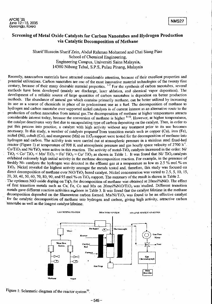
APeRE'05June 12-15,2005Gyeongju, Korea
INMS27 I
Screening of Metal Oxide Catalysts for Carbon Nanotubes and Hydrogen Productionvia Catalytic Decomposition of Methane
Sharif Hussein Sharif Zein, Abdul Rahman Mohamed and Chai Siang PiaoSchool of Chemical Engineering,
Engineering Campus, Universiti Sains Malaysia,14300 Nibong Tebal, S.P.S, Pulau Pinang, Malaysia
Figure 1: Schematic diagram of the reactor system lO•
-545-
{;AS ~f1XIN(;SYSTEM
"'.........
InI I
Recently, nanocarbon materials have attracted considerable attention, because of their excellent properties andpotential utilizations. Carbon nanotubes are one of the most innovative material technologies of the twenty firstcentury, because of their many desirable material properties. 1-7 For the synthesis of carbon nanotubes, severalmethods have been developed (mainly arc discharge, laser ablation, and chemical vapor deposition). Thedevelopment of a reliable source of large quantities of carbon nanotubes is dependent on better productionmethods. The abundance of natural gas which contains primarily methane, can be better utilized by increasingits use as a source of chemicals in place of its predominant use as a fuel. The decomposition of methane tohydrogen and carbon nanotube over supported nickel catalysts is of current interest as an alternative route to theproduction of carbon nanotubes from natural gas.The decomposition of methane at higher temperatures attractsconsiderable interest today, because the conversion of methane is higher 8-10. However, at higher temperatures,the catalyst deactivates very fast due to encapsulating type of carbon depositing on the catalyst. Thus, in order toput this process into practice, a catalyst with high activity without any treatment prior to its use becomesnecessary. In this study, a number of catalysts prepared~from transition metals such as .copper (Cu), iron (Fe),nickel (Ni), cobalt (Co), and manganese (Mn) on Ti(Ji' support were tested for the decomposition of methane intohydrogen and carbon. The activity tests were carried out at atmospheric pressure in a stainless steel fixed-bedreactor (Figure 1) at temperature of 998 K and atmospheric pressure and gas hourly space velocity of 2700 h-I.Co/Ti02and Ni/Ti02were active in this reaction. The activity ofmetal-Ti02catalysts increased in the order: NilTi02< Col Ti02< Mol TiO, ::= Fel TiO, ::= Cui TiO, as shown in Table 1. It was found that Nil Ti02catalystsexhibited extremely highinit"ial activity in the meth~e decomposition reaction. For example, in the presence offreshly Ni- catalysts the hydrogen was detected in the effiuentgas at a temperature as low as 2.5 % mol.% onTi02· Nickel re.vealed the highest activity amongst the metals tested and~ therefore, this study was focused ondirect decomposition of methane over NiO/Ti02 based catalyst. Nickel concentration was varied to 2.5, 5, 10, 15,.20,30,40,50,60, 70, 80, 90, and 95 mol % onTi02support. The summary of the result is shown in Table 2.
. The optimum NiO oxide doping on TiP2 for decomposition of methane was obtained at 20mol%NiO. The effectof first transition metals such as Cu; Fe, Co and Mn on 2Qmol%NiO/Ti02was studied. Different transitionmetals gave different reaction activities a~hoen in Table 3. It was found that the catalyst lifetime in the methanedecomposition depended on the filamentous carbon formed. MnlNi/TiO, was found to be an effective catalystfor the catalytic decomposition of methane into hydrogen and carbon, -giving high activity, attractive carbonnanotube as well as thelongest catalyst lifetime.
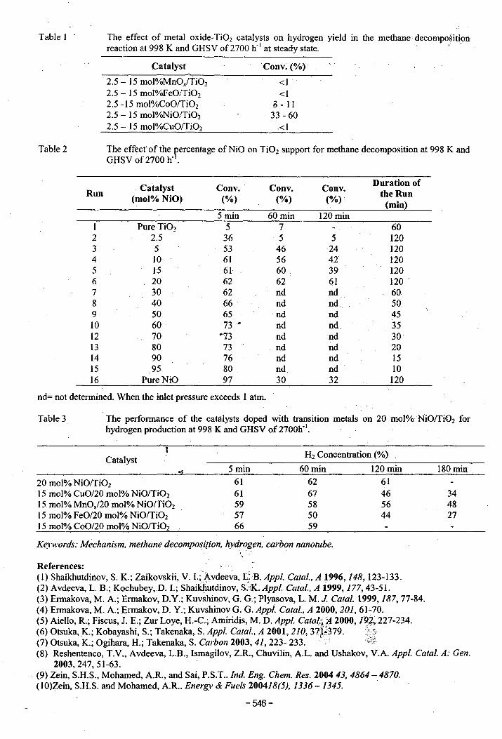
Table I . The effect of metal oxide-Ti02 catalysts on hydrogen yield in the methane'decompositioiireaction at 998 K and GHSV of2700 h- I at steady state. '. ...
Catalyst
2.5 - 15 mol%MnOx/Ti02
2.5 - 15 mol%FeO/Ti02
2;5 -15 mol%CoO/Ti02
2.5 - 15 mol%NiO/TiOi2.5 - 15 mol%CuO/Ti02
Cony. (%)
<I<1
B- 1133 - 60
<1
Table 2 The effect of the percentage ofNiO on Ti02 support for methane decomposition at 998 K andGHSV of 2700 h-I.
Catalyst Cony. Cony. Cony.Duration of
Run the Run(mol% NiO) (%) (%) (%).(min)
5 min 60 min 120 minI Pure Ti02 5 7 602 25 36 5 5 1203 5 53 46 24 1204 10 61 56 42 1205 15 61 60 39 1206 20 62 62 61 1207 30 62 nd nd 608 40 66 nd nd 509 50 65 nd nd 4510 60 73" nd nd 3512 70 "13 nd nd 3013 80 73 nd nd 2014 90 76 nd nd 1515 95 80 nd nd 1016 PureNiO 97 30 32 120
nd= not determined. When the inlet pressure exceeds 1 atm.
Table 3 The performance of the catalysts doped with transition metals on 20 mol%NiO/Ti02 forhydrogen production at 998 K and GHSVof2700h~l.
Catalyst
20 mol% NiO/Ti02
15 mol% CuO/20 mol% NiO/Ti02
15 mol% MnOx/20 mol% NiO/Ti02
15 mol% FeO/20 mol% NiO/Ti02
15 mol% CoO/20 mol% NiO/Ti02
5 min
6161595766
H2 Concentration (%)
60 min 120 min
62 6167 4658 5650 4459
180 min
344827
Keywords: Mechanism, methane decomposition, hydrog(!n, carbon nanotube..,References: .(I) Shaikhutdinov, S. K.; Zaikovskii, V. 1.;.Avdeeva, L;;B. Appl. Catal., A 1996, 148, 123-133.(2) Avdeeva, L. B.; Kochubey,D. I.; Shaikhutdinov, SJK. Appl. Cata/., A 1999, 177,43-51.(3) Ermakova, M. A; Ermakov, D.Y.; Kuvshinov, G. G.; Plyasova, L. M. J. Catal. 1999,187,77-84.(4) Ermakova, M. A; Ermakov, D. Y.; Kuvshinov G. G. Appl. Catal., A 2000,201,61'-70.(5) Aiello, R.; Fiscus, J. E.; Zur Loye, H.-C.; Amiridis, M. D. Appl. Cata~~l}. 2000, 19A227-234.(6) Otsuka, K.; Kobayashi, S.; Takenaka, S. Appl. Caral., A 2001, 210, 37~;379.:\;;(7) Otsuka, K.; Ogihara, H.; Takenaka, S. Carbon 2003, 41, 223- 233.' '~~f
(8) Reshentenco, T.V., Avdeeva, L.B., Ismagilov, Z.R., Chuvilin, AL. and Ushakov, V.A. Appl. Catal. A: Gen.2003,247,51-63.
(9) Zein, S.H.S., Mohamed, AR., and Sai, P.S.T.. Ind. Eng. Chem. Res. 200443, 4864 - 4870.(IO)Zein, S.H.S. and Mohamed, AR.. Energy & Fuels 200418(5), 1336 - 1345.
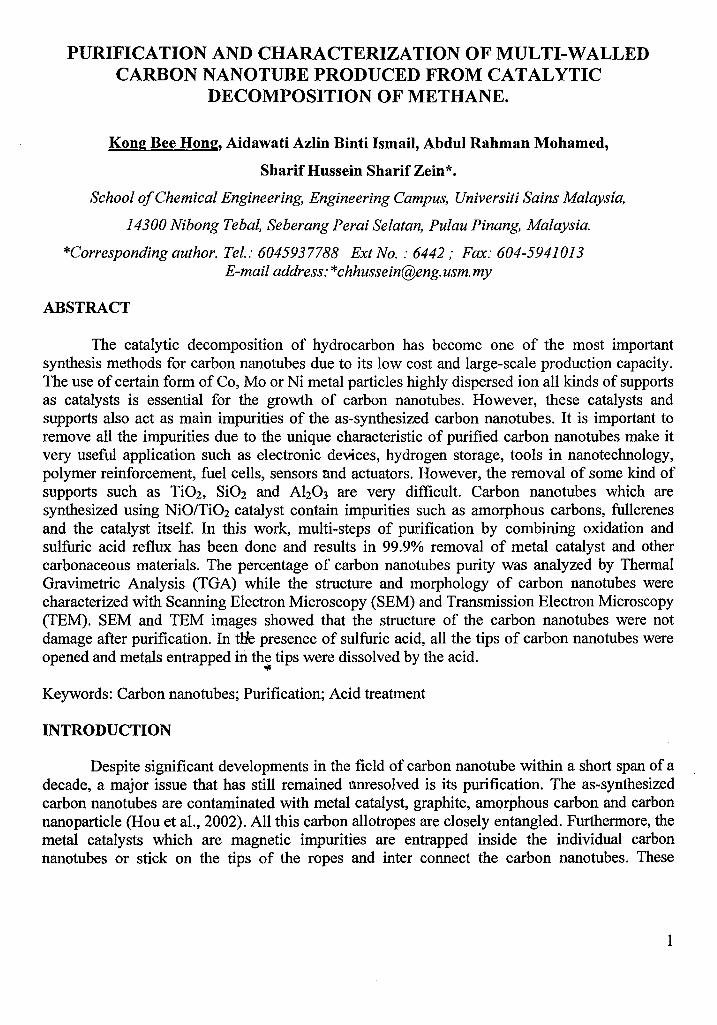
PURIFICATION AND CHARACTERIZATION OF MULTI-WALLEDCARBON NANOTUBE PRODUCED FROM CATALYTIC
DECOMPOSITION OF METHANE.
Kong Bee Hong, Aidawati Azlin Binti Ismail, Abdul Rahman Mohamed,
Sharif Hussein Sharif Zein*.
School ofChemical Engineering, Engineering Campus, Universiti Sains Malaysia,
14300 Nibong Tebal, Seberang Perai Selatan, Pulau Pinang, Malaysia.
*Corresponding author. Tel.: 6045937788 Ext No. : 6442,. Fax: 604-5941013E-mail address:*[email protected]
ABSTRACT
The catalytic decomposition of hydrocarbon has become one of the most importantsynthesis methods for carbon nanotubes due to its low cost and large-scale production capacity.The use of certain form of Co, Mo or Ni metal particles highly dispersed ion all kinds of supportsas catalysts is essential for the growth of carbon nanotubes. However, these catalysts andsupports also act as main impurities of the as-synthesized carbon nanotubes. It is important toremove all the impurities due to the unique characteristic of purified carbon nanotubes make itvery useful application such as electronic devices, hydrogen storage, tools in nanotechnology,polymer reinforcement, fuel cells, sensors and actuators. However, the removal of some kind ofsupports such as Ti02, Si02 and Ah03 are very difficult. Carbon nanotubes which aresynthesized using NiO/Ti02 catalyst contain impurities such as amorphous carbons, fullerenesand the catalyst itself. In this work, multi-steps of purification by combining oxidation andsulfuric acid reflux has been done and results in 99.9% removal of metal catalyst and othercarbonaceous materials. The percentage of carbon nanotubes purity was analyzed by ThermalGravimetric Analysis (TGA) while the structure and morphology of carbon nanotubes werecharacterized with Scanning Electron Microscopy (SEM) and Transmission Electron Microscopy(TEM). SEM and TEM images showed that the structure of the carbon nanotubes were notdamage after purification. In tHe presence of sulfuric acid, all the tips of carbon nanotubes wereopened and metals entrapped in the tips were dissolved by the acid.
OJ:
Keywords: Carbon nanotubes; Purification; Acid treatment
INTRODUCTION
Despite significant developments in the field of carbon nanotube within a short span of adecade, a· major issue that has still remained unresolved is its purification. The as-synthesizedcarbon nanotubes are contaminated with metal catalyst, graphite, amorphous carbon and carbon IInanoparticle (Hou et aI., 2002). All this carbon allotropes are closely entangled. Furthermore, themetal catalysts which are magnetic impurities are entrapped inside the individual carbonnanotubes or stick on the tips of the ropes and inter connect the carbon nanotubes. These
1
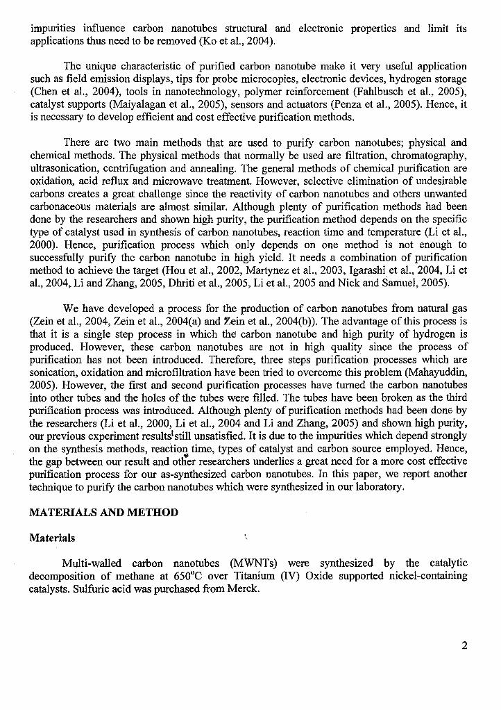
impurities influence carbon nanotubes structural and electronic properties and limit itsapplications thus need to be removed (Ko et aI., 2004).
The unique characteristic of purified carbon nanotube make it very useful applicationsuch as field emission displays, tips for probe microcopies, electronic devices, hydrogen storage(Chen et aI., 2004), tools in nanotechnology, polymer reinforcement (Fahlbusch et aI., 2005),catalyst supports (Maiyalagan et aI., 2005), sensors and actuators (Penza et aI., 2005). Hence, itis necessary to develop efficient and cost effective purification methods.
There are two main methods that are used to purify carbon nanotubes; physical andchemical methods. The physical methods that normally be used are filtration, chromatography,ultrasonication, centrifugation and annealing. The general methods of chemical purification areoxidation, acid reflux and microwave treatment. However, selective elimination of undesirablecarbons creates a great challenge since the reactivity of carbon nanotubes and others unwantedcarbonaceous materials are almost similar. Although plenty of purification methods had beendone by the researchers and shown high purity, the purification method depends on the specifictype of catalyst used in synthesis of carbon nanotubes, reaction time and temperature (Li et aI.,2000). Hence, purification process which only depends on one method is not enough tosuccessfully purify the carbon nanotube in high yield. It needs a combination of purificationmethod to achieve the target (Hou et aI., 2002, Martynez et aI., 2003, Igarashi et aI., 2004, Li etaI., 2004, Li and Zhang, 2005, Dhriti et aI., 2005, Li et aI., 2005 and Nick and Samuel, 2005).
We have developed a process for the production of carbon nanotubes from natural gas(Zein et aI., 2004, Zein et aI., 2004(a) and Zein et aI., 2004(b)). The advantage of this process isthat it is a single step process in which the carbon nanotube and high purity of hydrogen isproduced. However, these carbon nanotubes are not in high quality since the process ofpurification has not been introduced. Therefore, three steps purification processes which aresonication, oxidation and microfiltration have been tried to overcome this problem (Mahayuddin,2005). However, the first and second purification processes have turned the carbon nanotubesinto other tubes and the holes of the tubes were filled. The tubes have been broken as the thirdpurification process was introduced. Although plenty of purification methods had been done bythe researchers (Li et aI., 2000, Li et aI., 2004 and Li and Zhang, 2005) and shown high purity,our previous experiment results.lstill unsatisfied. It is due to the impurities which depend stronglyon the synthesis methods, reaction time, types of catalyst and carbon source employed. Hence,the gap between our result and otfu:r researchers underlies a great need for a more cost effectivepurification process for our as-synthesized carbon nanotubes. In this paper, we report anothertechnique to purify the carbon nanotubes which were synthesized in our laboratory.
MATERIALS AND METHOD
Materials ,,
Multi-walled carbon nanotubes (MWNTs) were synthesized by the catalyticdecomposition of methane at 650°C over Titanium (IV) Oxide supported nickel-containingcatalysts. Sulfuric acid was purchased from Merck.
2
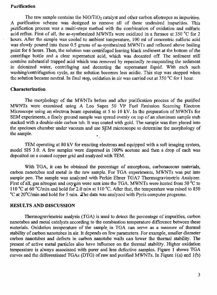
Purification~
t The raw sample contains the NiO/Ti02 catalyst and other carbon allotropes as impurities.A purification scheme was designed to remove all of these undesired impurities. Thispurification process was a multi-steps method with the combination of oxidation and sulfuricacid reflux. First of all, the as-synthesized MWNTs were oxidized in a furnace at 350°C for 2hours. After the sample was cooled to ambient temperature, 100 ml of concentric sulfuric acidwas slowly poured into these 0.5 grams of as-synthesized MWNTs and refluxed above boilingpoint for 6 hours. Then, the solution was centrifuged leaving black sediment at the bottom of thecentrifuge bottle and a clear supernatant acid, which was decanted off. The sediment stillcontains substantial trapped acid which was removed by repeatedly re-suspending the sedimentin deionized water, centrifuging and decanting the supernatant liquid. With each suchwashing/centrifugation cycle, as the solution becomes less acidic. This step was stopped whenthe solution became neutral. In final step, oxidation in air was carried out at 350°C for 1 hour.
Characterization
The morphology of the MWNTs before and after purification process of the purifiedMWNTs were examined using A Leo Supra 50 VP Fuel Emission Scanning ElectronMicroscope using an electron beam operating at 5 to 10 kV. In the preparation of MWNTs forSEM experiments, a finely ground sample was spread evenly on top of an aluminum sample stubstacked with a double-side carbon tab. It was coated with gold. The sample was then placed intothe specimen chamber under vacuum and use SEM microscope to determine the morphology ofthe sample. ~
TEM operating at 80 kV for exacting electrons and equipped with a soft imaging system,model SIS 3.0. A few samples were dispersed in 100% acetone and then a drop of each wasdeposited on a coated copper grid and analyzed with TEM.
With TGA, it can be obtained the percentage of amorphous, carbonaceous materials,carbon nanotubes and metal in the raw sample. For TGA experiments, MWNTs was put intosample pen. The sample was analyzed with Perkin Elmer TGA7 Thermogravimetric Analyzer.First of all, gas nitrogen and oxy~en were sent into the TGA. MWNTs were heated from 50°C to110°C at 60 °C/min and hold for 2.0 min at 110°C. After that, the temperature was raised to 850°c at 20°C/min and hold for 5 min. .;fhe data was analyzed with Pyris computer programs.
RESULTS AND DISCUSSION
Thermogravimetric analysis (TGA) is used to detect the percentage of impurities, carbonnanotubes and metal catalysts according to the combustion temperature difference between thesematerials. Oxidation temperature of the sample, in TGA can serve as a measure of thermalstability of carbon nanotubes in air. It depends onfew parameters. For example, smaller diametercarbon nanotubes and defects in carbon nanotube walls can lower the thermal stability. Thepresent of active metal particles also have influence on the thermal stability. Higher oxidationtemperature is always associated with purer and less defective samples. Figure 1 shows TGAcurves and the differentiated TGAs (DTG) of raw and purified MWNTs. In Figure l(a) and 1(b)
3
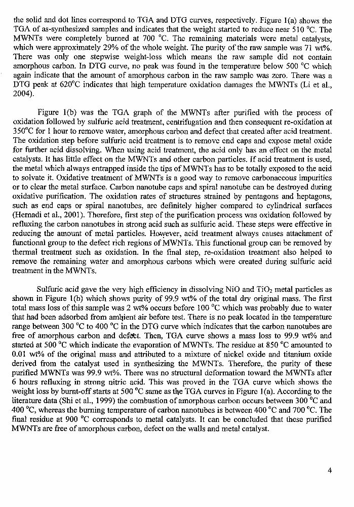
the solid and dot lines correspond to TGA and DTG curves, respectively. Figure l(a) shows theTGA of as-synthesized samples and indicates that the weight started to reduce near 510°C. TheMWNTs were completely burned at 700°C. The remaining materials were metal catalysts,which were approximately 29% of the whole weight. The purity of the raw sample was 71 wt%.There was only one stepwise weight-loss which means the raw sample did not containamorphous carbon. In DTG curve, no peak was found in the temperature below 500°C whichagain indicate that the amount of amorphous carbon in the raw sample was zero. There was aDTG peak at 620°C indicates that high temperature oxidation damages the MWNTs (Li et aI.,2004).
Figure l(b) was the TGA graph of the MWNTs after purified with the process ofoxidation followed by sulfuric acid treatment, centrifugation and then consequent re-oxidation at350°C for 1 hour to remove water, amorphous carbon and defect that created after acid treatment.The oxidation step before sulfuric acid treatment is to remove end caps and expose metal oxidefor further acid dissolving. When using acid treatment, the acid only has an effect on the metalcatalysts. It has little effect on the MWNTs and other carbon particles. If acid treatment is used,the metal which always entrapped inside the tips of MWNTs has to be totally exposed to the acidto solvate it. Oxidative treatment of MWNTs is a good way to remove carbonaceous impuritiesor to clear the metal surface. Carbonnanotube caps and spiral nanotube can be destroyed duringoxidative purification. The oxidation rates of structures strained by pentagons and heptagons,such as end caps or spiral nanotubes, are definitely higher compared to cylindrical surfaces(Hernadi et aI., 2001). Therefore, first step of the purification process was oxidation followed byrefluxing the carbon nanotubes in strong acid such as sulfuric acid. These steps were effective inreducing the amount of metal particles. Ho.\Yever, acid treatment always causes attachment offunctional group to the defect rich regions of MWNTs. This functional group can be removed bythermal treatment such as oxidation. In the final step, re-oxidation treatment also helped toremove the remaining water and amorphous carbons which were created during sulfuric acidtreatment in the MWNTs.
Sulfuric acid gave the very high efficiency in dissolving NiO and Ti02 metal particles asshown in Figure l(b) which shows purity of 99.9 wt% of the total dry original mass. The firsttotal mass loss of this sample was 2 wt% occurs before 100°C which was probably due to waterthat had been adsorbed from aniqient air before test. There is no peak located in the temperaturerange between 300°C to 400 °c in the DTG curve which indicates that the carbon nanotubes arefree of amorphous carbon and defett. Then, TGA curve shows a mass loss to 99.9 wt% andstarted at 500°C which indicate the evaporation of MWNTs. The residue at 850°C amounted to0.01 wt% of the original mass and attributed to a mixture of nickel oxide and titanium oxidederived from the catalyst used in synthesizing the MWNTs. Therefore,,, the purity of thesepurified MWNTs was 99.9 wt%. There was no structural deformation toward the MWNTs after6 hours refluxing in strong nitric acid. This was proved in the TGA curve which shows theweight loss by burnt-off starts at 500°C same as t~e TGA curves in Figure l(a). According to theliterature data (Shi et aI., 1999) the combustion of amorphous carbon occurs between 300°C and400 °c, whereas the burning temperature of carbon nanotubes is between 400°C and 700 °c. Thefinal residue at 900°C corresponds to metal catalysts. It can be concluded that these purifiedMWNTs are free ofamorphous carbon, defect on the walls and metal catalyst.
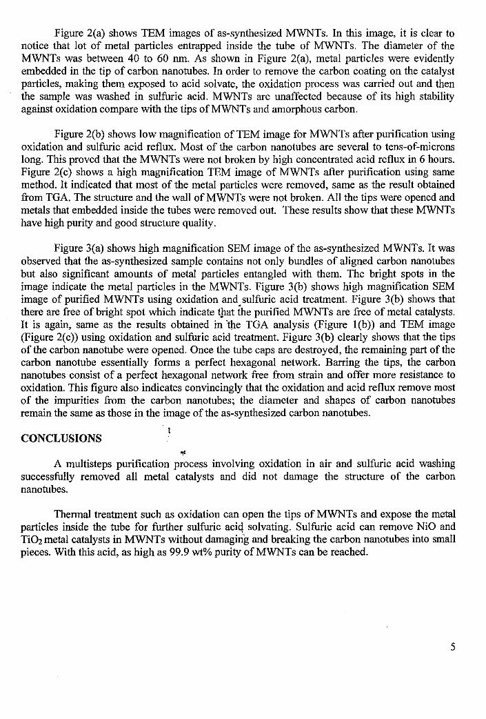
Figure 2(a) shows TEM images of as-synthesized MWNTs. In this image, it is clear tonotice that lot of metal particles entrapped inside the tube of MWNTs. The diameter of theMWNTs was between 40 to 60 nm. As shown in Figure 2(a), metal particles were evidentlyembedded in the tip of carbon nanotubes. In order to remove the carbon coating on the catalystparticles, making them exposed to acid solvate, the oxidation process was carried out and thenthe sample was washed in sulfuric acid. MWNTs are unaffected because of its high stabilityagainst oxidation compare with the tips of MWNTs and amorphous carbon.
Figure 2(b) shows low magnification of TEM image for MWNTs after purification usingoxidation and sulfuric acid reflux. Most of the carbon nanotubes are several to tens-of-micronslong. This proved that the MWNTs were not broken by high concentrated acid reflux in 6 hours.Figure 2(c) shows a high magnification TEM image of MWNTs after purification using samemethod. It indicated that most of the metal particles were removed, same as the result obtainedfrom TGA. The structure and the wall of MWNTs were not broken. All the tips were opened andmetals that embedded inside the tubes were removed out. These results show that these MWNTshave high purity and good structure quality.
Figure 3(a) shows high magnification SEM image of the as-synthesized MWNTs. It wasobserved that the as-synthesized sample contains not only bundles of aligned carbon nanotubesbut also significant amounts of metal particles entangled with them. The bright spots in theimage indicate the metal particles in the MWNTs. Figure 3(b) shows high magnification SEMimage of purified MWNTs using oxidation and sulfuric acid treatment. Figure 3(b) shows thatthere are free of bright spot which indicate tpat the purified MWNTs are free of metal catalysts.It is again, same as the results obtained in "the TGA analysis (Figure l(b)) and TEM image(Figure 2(c)) using oxidation and sulfuric acid treatment. Figure 3(b) clearly shows that the tipsof the carbon nanotube were opened. Once the tube caps are destroyed, the remaining part of thecarbon nanotube essentially forms a perfect hexagonal network. Barring the tips, the carbonnanotubes consist of a perfect hexagonal network free from strain and offer more resistance tooxidation. This figure also indicates convincingly that the oxidation and acid reflux remove mostof the impurities from the carbon nanotubes; the diameter and shapes of carbon nanotubesremain the same as those in the image of the as-synthesized carbon nanotubes.
ICONCLUSIONS
A multisteps purification process involving oxidation in air and sulfuric acid washingsuccessfully removed all metal catalysts and did not damage the structure of the carbonnanotubes.
Thermal treatment such as oxidation can open the tips of MWNTs and expose the metalparticles inside the tube for further sulfuric aciq solvating. Sulfuric acid can remove NiO andTi02 metal catalysts in MWNTs without damaging and breaking the carbon nanotubes into smallpieces. With this acid, as high as 99.9 wt% purity ofMWNTs can be reached.
5
ACKNOWLEDGEMENTS
The authors acknowledge for the financial support provided by Akademik Sains Malaysiaunder Fundamental SAGA Grant (Project: AlC No: 6053001) and Short Term Grant (Project:AlC No: 6035146).
REFERENCES
Chen, Y., Ciuparu, D., Lim, S., Yang, Y., Haller, G.L., Pfefferle, L. (2004) Synthesis ofuniform diameter single-walled carbon nanotubes in Co-MCM-41: effects of thecatalyst prereduction and nanotube growth temperature. J. of Catal. 225,453-465.
Dhriti, N., Dong, S. K., Kurt, E.G. (2005) A facile and rapid purification method for singlewalled carbon nanotubes. Carbon 43, 651-673.
Fahlbusch, St., Mazerolle, S., Breguet, lM., Steinecker, A., Agnusd, J., P'erez, R., Michler J.(2005) Nanomanipulation in a scanning electron microscope. J. of Mater. Proc. Tech.167,371-382.
Hernadi, K., Siska, A., Thien-Nga, L., Forro, L., Kiricsi, 1. (2001) Reactivity of different kindsof carbon during oxidative purification of catalytically prepared carbon nanotubes.Solid State Ion. 141-142,203-209.
Hou, p.x., Bai, S., Yang, Q.H., Liu, C., Cheng, H.M. (2002) Multi-step purification of carbonnanotubes. Carbon 40,81-85.
Igarashi, H., Murakami, H., Murakami, Y., Maruyama, S., Nakashima, N. (2004) Purificationand characterization ofzeolite-supportocl. Chern. Phys. Lett. 392, 529-532.
Ko, C.J., Lee, C.Y., Ko, F.H., Chen, H:i.., Chu, T.C. (2004) Highly efficient microwaveassisted purification of multiwalled 'carbon nanotubes. Microelec. Eng. 73-74, 570577.
Li, F., Cheng, H.M., Xing, Y.T., Tan, P.H., Su, G. (2000) Purification of single-walled carbonnanotubes synthesized by the catalytic decomposition of hydrocarbons. Carbon 38,2041-2045.
Li, H.l, Feng, L., Guan, L.H., Shi, Z.J., Gu, Z.N. (2004) Synthesis and purification of singlewalled carbon nanotubes in the cottonlike soot. Solid State Commun. 132,219-224.
Li, J.Y., Zhang, Y.Z. (2005) A simple purification for single-walled carbon nanotubes. Phys. E.28, 309-312. ~
Mahayuddin, M.E.B.M. (2005) Purification of carbon nanotubes. Universiti Sains Malaysia,Final year project. '!l
Maiyalagan, T., Viswanathan, B., Varadaraju U.V. (2005) Nitrogen containing carbonnanotubes as supports for Pt - Alternate anodes for fuel cell applications. Electrochem.Commun.7,905-912.
MartYnez, M.T., Callejas, M.A., Benito, A.M., Cochet M., Seeger T., Anson A., Schreiber, J.,Gordon, C., Marhic, C., Chauvet, 0., Fierroa, J.L.G., Maser, W.K. (2003) Sensitivity ofsingle wall carbon nanotubes to Qxidative processing: structural modification,intercalation and functionalisation. Carbon 41,2247-2256.
Nick, E. T., Samuel, G. L. (2005) Purification and defect elimination of single-walled carbonnanotubes by the thermal reduction technique. Nanotech. 16,639-646.
6
Penza, M., Tagliente, M.A., Aversa, P., Cassano, G. (2005) Organic-vapor detection usingcarbon-nanotubes nanocomposite microacoustic sensors. Chem. Phys. Lett. 409, 349354.
Shi, Z., Lian, Y, Liao, F., Zhou, X., Gu, Z., Zhang, Y, Iijima, S. (1999) Purification of singlewalled carbon nanotubes. Solid State Commun. 112,35.
Zein, S.H.S. and Mohamed, A.R. (2004) Mn/Ni/Ti02 catalyst for the production of hydrogenand carbon nanotubes from methane decomposition. Energy & Fuels 18, 1336 -1345.
Zein, S.H.S., Mohamed, A.R., and Sai, P.S.T. (2004b) Kinetic studies on catalyticdecomposition of methane to hydrogen and carbon over Ni/Ti02 catalyst. Ind. Eng.Chem. Res. 43, 4864 - 4870.
Zein, S.H.S., Mohamed, A.R., Sai, P.S.T., Zabidi, N.A.M. (2004a) Production of hydrogen andcarbon nanotubes from methane. J. Ind. & Eng. Chem. 43, 4864 - 4870.
Zhu, X.Y., Lee, S.M., Lee, YH., Frauenheim, T. (2000) Adsorption and Desorption of an O2Molecule on Carbon Nanotubes. Phys. Rev. Lett. 85, 2757-2760
LIST OF FIGURE
Figurel. TGA graph of (a) as synthesized MWNTs. (b) MWNTs after purification usingoxidation and sulfuric acid treatment.
Figure 2. TEM image of (a) unpurified MWNTs. (b) low magnification of purified MWNTsusing sulfuric acid treatment arid oxidation. (c) high magnification of purifiedMWNTs using sulfuric acid treatment and oxidation.
Figure 3. SEM image of (a) high magnification of unpurified MWNTs. (b) high magnificationof purified MWNTs using sulfuric acid treatment and oxidation (The circle markindicate the opened tip of MWNT).
.,
7
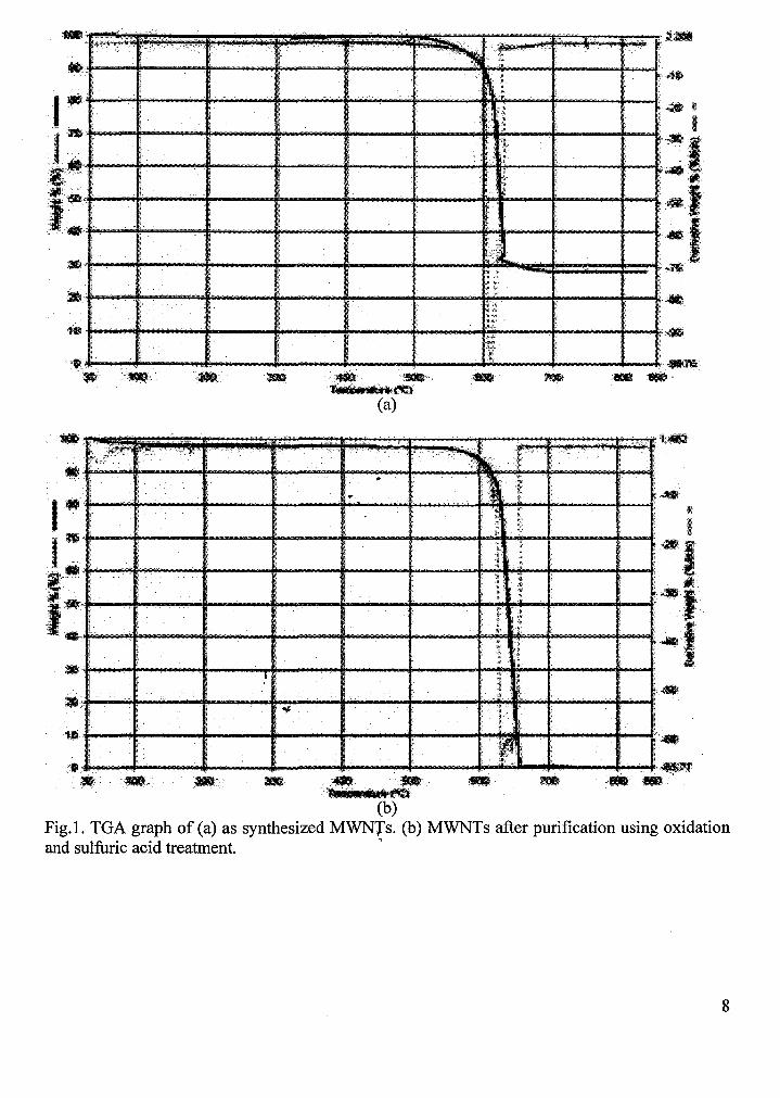
I"I:+--'"""i!'-_-t---.......-_........~--+---""!-., .....,._",,."f!-"""f!--.....--...........--+---+--............;....
..•.+~... - ......--~i-o--+--- ...--....o.i--......~--4---...;~.....;; ..•,~••e··B:· ..'.' __ ..
1§itltil··_.~
(a)
a,."--f---"""f---+.~.--+--~---
.f--....---+---........---+--........----+~'. ,~_.. ;_::.' - :- .'......
l'Il*lll.~.
(b)Fig.I. TGA graph of (a) as synthesized MWNTs. (b) MWNTs after purification using oxidationand sulfuric acid treatment. '
8
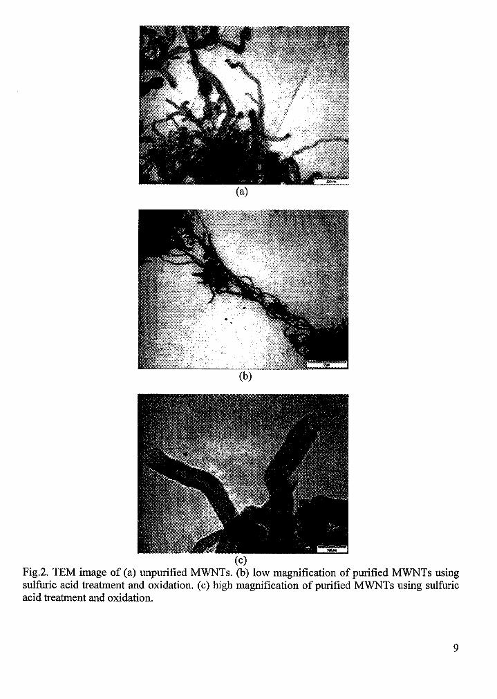
(a)
(c)Fig.2. TEM image of (a) unpurified MWNTs. (b) low magnification of purified MWNTs usingsulfuric acid treatment and oxidation. (c) high magnification of purified MWNTs using sulfuricacid treatment and oxidation.
9
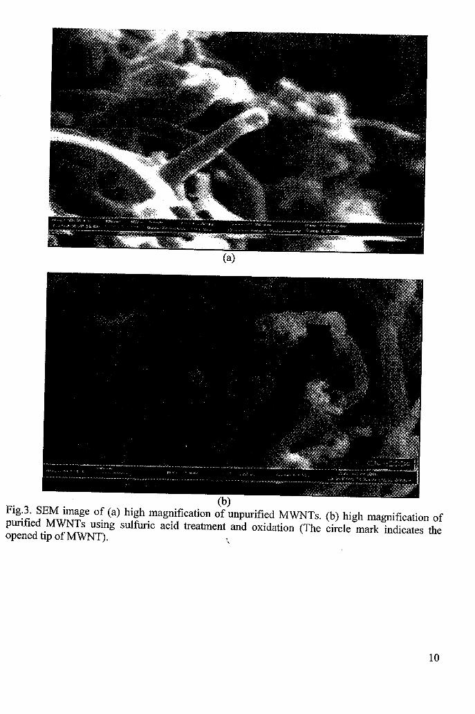
(b)Fig.3. SEM image of (a) high magnification of unpurified MWNTs. (b) high magnification ofpurified MWNTs using sulfuric acid treatment and oxidation (The circle mark indicates theopened tip ofMWNT). "
10
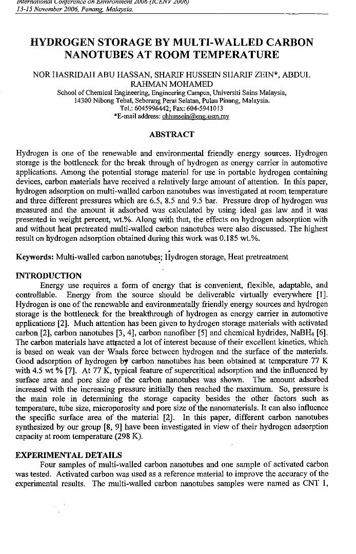
internatlonal COnJerence on l!;nvironmen13-15 November 2006, Penang, Malaysia.
HYDROGEN STORAGE BY MULTI-WALLED CARBONNANOTUBES AT ROOM TEMPERATURE
NOR HASRIDAH ABU HASSAN, SHARIF HUSSEIN SHARIF ZEIN*, ABDULRAHMAN MOHAMED
School ofChemical Engineering, Engineering Campus, Universiti Sains Malaysia,14300 Nibong Tebal, Seberang Perai Selatan, Pulau Pinang, Malaysia.
Tel.: 6045996442; Fax: 604-5941013*E-mail address:[email protected]
ABSTRACT
Hydrogen is one of the renewable and environmental friendly energy sources. Hydrogenstorage is the bottleneck for the break through of hydrogen as energy carrier in automotiveapplications. Among the potential storage material for use in portable hydrogen containingdevices, carbon materials have received a relatively large amount of attention. In this paper,hydrogen adsorption on multi-walled carbon nanotubes was investigated at room temperatureand three different pressures which are 6.5, 8.5 and 9.5 bar. Pressure drop of hydrogen wasmeasured and the amount it adsorbed was calculated by using ideal gas law and it waspresented in weight percent, wt.%. Along with that, the effects on hydrogen adsorption withand without heat pretreated multi-walled carbon nanotubes were also discussed. The highestresult on hydrogen adsorption obtained during this work was 0.185 wt.%.
'"Keywords: Multi-walled carbon nanotub~~; Hydrogen storage, Heat pretreatment
INTRODUCTIONEnergy use requires a form of energy that is convenient, flexible, adaptable, and
controllable. Energy from the source should be deliverable virtually everywhere [1].Hydrogen is one of the renewable and environmentally friendly energy sources and hydrogenstorage is the bottleneck for the breakthrough of hydrogen as energy carrier in automotiveapplications [2]. Much attention has been given to hydrogen storage materials with activatedcarbon [2], carbon nanotubes [3,4], carbon nanofiber [5] and chemical hydrides, NaBH4 [6].The carbon materials have attracted a lot of interest because of their excellent kinetics, whichis based on weak van der Waals force between hydrogen and the surface of the materials.Good adsorption of hydrogen by carbon nanotubes has been obtained at temperature 77 Kwith 4.5 wt % [7]. At 77 K, typical feature of supercritical adsorption and the influenced bysurface area and pore size of the carbon nanotubes was shown. The amount adsorbedincreased with the increasing pressure initially then reached the maximum. So, pressure isthe main role in determining the storage capacity besides the other factors such astemperature, tube size, microporosity and pore size of the nanomaterials. It can also influencethe specific surface area of the material [2). In this paper, different carbon nanotubessynthesized by our group [8, 9] have been investigated in view of their hydrogen adsorptioncapacity at room temperature (298 K).
EXPERIMENTAL DETAILSFour samples of multi-walled carbon nanotubes and one sample of activated carbon
was tested. Activated carbon was used as a reference material to improve the accuracy of theexperimental results. The multi-walled carbon nanotubes samples were named as CNT 1,
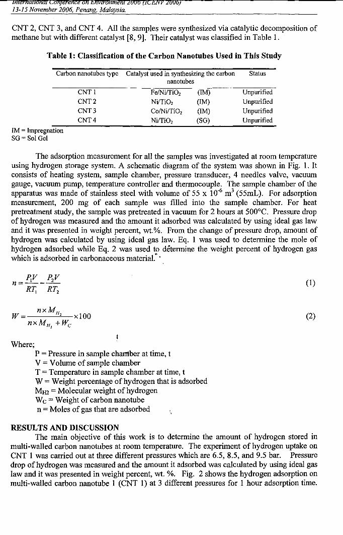
CNT 2, CNT 3, and CNT 4. All the samples were synthesized via catalytic decomposition ofmethane but with different catalyst [8, 9]. Their catalyst was classified in Table 1.
Table 1: Classification of the Carbon Nanotubes Used in This Study
Carbon nanotubes type Catalyst used in synthesizing the carbon Statusnanotubes
1M = ImpregnationSG= Sol Gel
CNTICNT2CNT3CNT4
FelNi/TiOzNi/TiOzColNi/TiOzNi/TiOz
(1M)
(1M)(1M)
(SG)
Unpurified
UnpurifiedUnpurifiedUnpurified
The adsorption measurement for all the samples was investigated at room temperatureusing hydrogen storage system. A schematic diagram of the system was shown in Fig. 1. Itconsists of heating system, sample chamber, pressure transducer, 4 needles valve, vacuumgauge, vacuum pump, temperature controller and thermocouple. The sample chamber of theapparatus was made of stainless steel with volume of 55 x 10-6 m3 (55mL). For adsorptionmeasurement, 200 mg of each sample was filled into the sample chamber. For heatpretreatment study, the sample was pretreated in vacuum for 2 hours at 500°C. Pressure dropof hydrogen was measured and the amount it adsorbed was calculated by using ideal gas lawand it was presented in weight percent, wt.%. From the change of pressure drop, amount ofhydrogen was calculated by using ideal gas law. Eq. 1 was used to determine the mole ofhydrogen adsorbed while Eq. 2 was used to determine the weight percent of hydrogen gaswhich is adsorbed in carbonaceous material." .
,,
~v P2Vn=-----
R~ RT2
Where;P = Pressure in sample chamber at time, tV = Volume of sample chamberT = Temperature in sample chamber at time, tW = Weight percentage ofhydrogen that is adsorbedMH2 = Molecular weight ofhydrogenWe = Weight of carbon nanotuben = Moles of gas that are adsorbed
(1)
(2)
RESULTS AND DISCUSSIONThe main objective of this work is to determine the amount of hydrogen stored in
multi-walled carbon nanotubes at room temperature. The experiment of hydrogen uptake onCNT 1 was carried out at three different pressures which are 6.5, 8.5, and 9.5 bar. Pressuredrop ofhydrogen was measured and the amount it adsorbed was calculated by using ideal gaslaw and it was presented in weight percent, wt. %. Fig. 2 shows the hydrogen adsorption onmulti-walled carbon nanotube 1 (CNT 1) at 3 different pressures for 1 hour adsorption time.
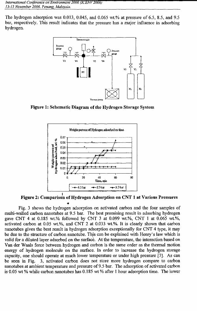
V2 \fl.
6)
V5 V6
Vacuum pump IC--_..:>J
PresSuregaug.
The hydrogen adsorption was 0.013, 0.045, and 0.065 wt.% at pressure of 6.5, 8.5, and 9.5bar, respectively. This result indicates that the pressure has a major influence in adsorbinghydrogen.
Pressure
"---+X f--'--IXI---4la:_---....J'-.--1')I(!-l-:;gauge
Figure 1: Schematic Diagram of the Hydrogen Storage System
0,07 ,_ _ - - .._ _ __ _.._ _,
O.US +-- ---'s'---- ~!t""------IIQ:05 +--~...z....,,.............--~--li--J,,,~---j
0:Q4 +-----'------)..~..iL-..]-----j.JrH
0:03+-~~-~~~~-~~-4
0;02 j jf
0:0~... :1// ~
o 20 40Thp~,nlin
80
IFigure 2: Comparison of Hydrogen Adsorption on CNT 1 at Various Pressures
'iC
Fig. 3 shows the hydrogen adsorption on activated carbon and the four samples ofmulti-walled carbon nanotubes at 9.5 bar. The best promising result in adsorbing hydrogengave CNT 4 at 0.185 wt.% followed by CNT 3 at 0.099 wt.%, CNT 1 at 0.065 wt.%,activated carbon at 0.05 wt.%, and CNT 2 at 0.033 wt.%. It is clearly shown that carbonnanotubes gives the best result in hydrogen adsorption exceptionally for CNT 4 type, it maybe due to the structure of carbon nanotube. Thjs can be explained with Henry's law which isvalid for a diluted layer adsorbed on the surface. At the temperature, the interaction based onVander Waals force between hydrogen and carbon is the same order as the thermal motionenergy of hydrogen molecule on the surface. In order to increase the hydrogen storagecapacity, one should operate at much lower temperature or under high pressure [7]. As canbe seen in Fig. 3, activated carbon does not store more hydrogen compare to carbonnanotubes at ambient temperature and pressure of9.5 bar. The adsorption of activated carbonis 0.05 wt % while carbon nanotubes has 0.185 wt % after 1 hour adsorption time. The lower
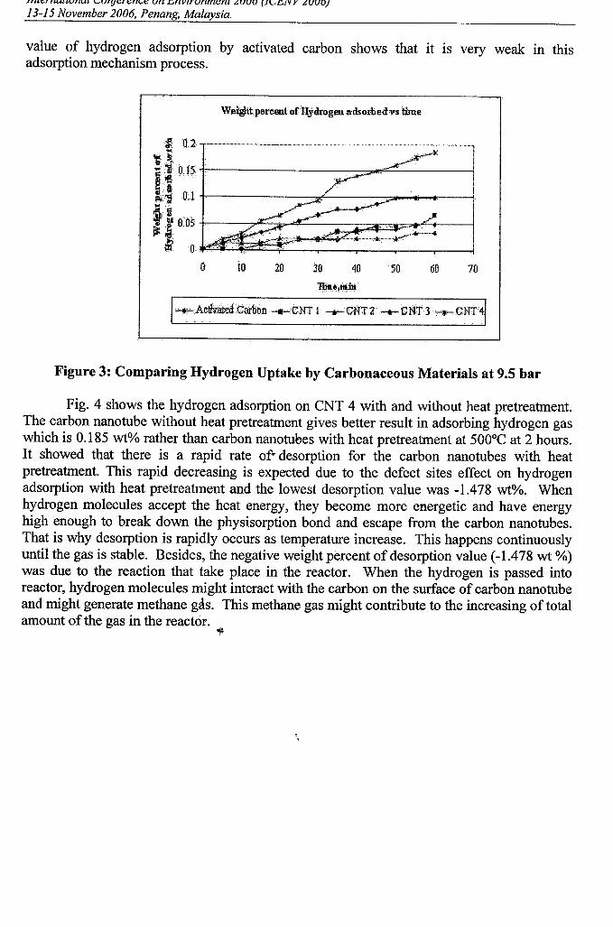
International Conference on Environment13-15 November 2006, Penang, Malaysia.
value of hydrogen adsorption by activated carbon shows that it IS very weak III thisadsorption mechanism process.
Weiglitpereent·ofJly.drogenadsomedvs time
70
JI
50 6040302010
.'C; 0.:2 ,. .- .- _ .- .- "1
:~. ._c~'t.J ~.' .1::.10.t5 "j-----------=~~""'.."'-.--------i" 16.·.· ....S>~ .'·AO··~ .O.l+-------..",f-----:::;ol_..-....---j"'lij WI ......•
~..~••. 0.05...;:1:1. {l.
{l
Figure 3: Comparing Hydrogen Uptake by Carbonaceous Materials at 9.5 bar
Fig. 4 shows the hydrogen adsorption on CNT 4 with and without heat pretreatment.The carbon nanotube without heat pretreatment gives better result in adsorbing hydrogen gaswhich is 0.185 wt% rather than carbon nanotubes with heat pretreatment at 500°C at 2 hours.It showed that there is a rapid rate of· desorption for the carbon nanotubes with heatpretreatment. This rapid decreasing is expected due to the defect sites effect on hydrogenadsorption with heat pretreatment and the lowest desorption value was -1.478 wt%. Whenhydrogen molecules accept the heat energy, they become more energetic and have energyhigh enough to break down the physisorption bond and escape from the carbon nanotubes.That is why desorption is rapidly occurs as temperature increase. This happens continuouslyuntil the gas is stable. Besides, the negative weight percent of desorption value (-1.478 wt %)was due to the reaction that take place in the reactor. When the hydrogen is passed intoreactor, hydrogen molecules might interact with the carbon on the surface of carbon nanotubeand might generate methane gas. This methane gas might contribute to the increasing of totalamount of the gas in the reactor.
'\l
,,
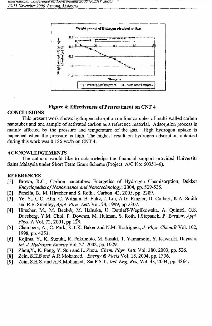
0.2 ~~~~~~~::-:=."''''..=.'''===l.
-·1•.8" "" _.._ _ _ _ _ _- _ •..•.._.__ _ -_.._ -
T'Ull,Il;JliiJl
'Weigh~percentof'lfydrogen adsorbed vs tiIm
Figure 4: Effectiveness of Pretreatment on CNT 4CONCLUSIONS
This present work shows hydrogen adsorption on four samples of multi-walled carbonnanotubes and one sample of activated carbon as a reference material. Adsorption process ismainly affected by the pressure and temperature of the gas. High hydrogen uptake ishappened when the pressure is high. The highest result on hydrogen adsorption obtainedduring this work was 0.185 wt.% on CNT 4.
ACKNOWLEDGEMENTSThe authors would like to acknowledge the financial support provided Universiti
Sains Malaysia under Short Term Grant Scheme (Project: AlC No: 6035146).
REFERENCES[1] Brown, RC., Carbon nanotubes: Energetics of Hydrogen Chemisorption, Dekker
Encyclopedia ofNanoscience and Nanotechnology, 2004, pp. 529-535.[2] Panella, B., M. Hirscher and S. Roth. Carbon 43,2005, pp. 2209.[3] Ye, Y., C.C. Ahn, C. Witham, B. Fultz, 1. Liu, A.G. Rinzler, D. Colbert, K.A. Smith
and RE. Smalley, Appl.Phys. Lett. Vol. 74,1999, pp 2307.[4] Hirscher, M., M. Beche.\", M. Haluska, U. Detdaff-Weglikowska, A. Quintel, G.S.
Duesberg, Y.M. Choi, P. Downes, M. Hulman, S. Roth, LStepanek, P. Bernier, Appl.Phys. A Vol. 72,2001, pp.l1'9.
[5] Chambers, A., C. Park, RT.K. Baker and N.M. Rodriguez, J Phys. Chern.B Vol. 102,I998,pp.4253.
[6] Kojima, Y., K. Suzuki, K. Fukumoto, M. Sasaki, T. Yamamoto, Y. Kawai,H. Hayashi,Int. J Hydrogen Energy Vol. 27, 2002, pp. 1029.
[7] Zhou,Y., K. Feng, Y. Sun and L. Zhou. Chern. Phys. Lett. Vol. 380, 2003, pp. 526.[8] Zein, S.H.S and A.RMohamed.. Energy i& Fuels Vol. 18,2004, pp. 1336.[9] Zein, S.H.S. and A.RMohamed, Sai P.S.T., Ind Eng. Res. Vol. 43,2004, pp. 4864.
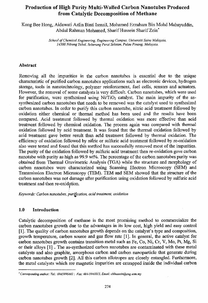
Production of High Purity Multi-Walled Carbon Nanotubes Producedfrom Catalytic Decomposition of Methane
Kong Bee Hong, Aidawati Azlin Binti Ismail, Mohamed Ezzaham Bin Mohd Mahayuddin,Abdul Rahman Mohamed, Sharif Hussein Sharif Zein*
School alChemical Engineering, Engineering Campus, Universiti Sains Malaysia,14300 Nibong Tebal, Seberang Perai Selatan, Pulau Pinang, Malaysia.
Abstract
Removing all the impurities in the carbon nanotubes is essential due to the uniquecharacteristic of purified carbon nanotubes applications such as electronic devices, hydrogenstorage, tools in nanotechnology, polymer reinforcement, fuel cells, sensors and actuators.However, the removal of some catalysts is very difficult. Carbon nanotubes, which were usedfor purification, were synthesized using Ni/TiOz catalyst. The main impurity of the assynthesized carbon nanotubes that needs to be removed was the catalyst used to synthesizedcarbon nanotubes. In order to purify this carbon nanotube, nitric acid treatment followed byoxidation either chemical or thermal method has been used and the results have beencompared. Acid treatment followed by thermal oxidation was more effective than acidtreatment followed by chemical oxidation. The process again was compared with thermaloxidation followed by acid treatment. It was found that the thermal oxidation followed byacid treatment gave better result than ac1d treatment followed by thermal oxidation. Theefficiency of oxidation followed by nifric or sulfuric acid treatment followed by re-oxidationalso were tested and found that this method has successfully removed most of the impurities.The purity of the oxidation followed by sulfuric acid treatment then re-oxidation gave carbonnanotube with purity as high as 99.9 wt%. The percentage of the carbon nanotubes purity wasobtained from Thermal Gravimetric Analysis (TGA) while the structure and morphology ofcarbon nanotubes were characterized using Scanning Electron Microscopy (SEM) andTransmission Electron Microscopy (TEM). TEM and SEM showed that the structure of thecarbon nanotubes was not damage after purification using oxidation followed by sulfuric acidtreatment and then re-oxidation.
I
Keywords: Carbon nanotubes, purification, acid treatment, oxidation
1.0 Introduction
Catalytic decomposition of methane is the most promising method to commercialize thecarbon nanotubes growth due to the advantages in its low cost, high yield and easy control[1]. The quality of carbon nanotubes growth depends on the catalyst's type and composition,growth temperature, carbon source and gas flow rate [1]. In general, the active catalyst forcarbon nanotubes growth contains transition metal such as Fe, Co, Ni, Cr, V, Mo, Pt, Mg, Sior their alloys [1] • The as-synthesized carbon nanotubes are contaminated with these metalcatalysts and also graphite, amorphous carbon and carbon nanoparticle that generate duringcarbon nanotubes growth [2]. All this carbon allotropes are closely entangled. Furthermore,the metal catalysts which are magnetic impurities are entrapped inside the individual carbon
•Corresponding author: Tel.: 6045996442 .. Fax: 604-5941013, Email: [email protected]
274
nanotubes or stick on the tips of the ropes and inter connect the carbon nanotubes.Consequently, their purification is a very difficult problem.
The impurities impede utilization of the unique properties of carbon nanotubes; therefore it isneeded to be removed for further application [3,4], The purified carbon nanotube can beapplied in many field such as emission displays, tips for probe microcopies, nanoelectronicdevices [5], hydrogen storage [6], tools in nanotechnology, polymer reinforcement [7],catalyst supports [8], sensors and actuators [9]. Hence, it is necessary to develop efficient andcost effective purification methods to produce pure carbon nanotubes.
The methods that are normally be used to purify carbon nanotubes are thermal oxidation,filtration, chromatography, ultrasonication, centrifugation, annealing, chemical oxidation,acid reflux and microwave treatment. However, selective elimination of undesirable carbonscreates a great challenge especially amorphous carbon and carbon nanoparticle because theiroxidation temperature is similar to those of carbon nanotubes [4]. There are many method topurify carbon nanotubes and have successfully remove most of the impurities. Jeong et al.achieved carbon nanotubes purity more than 95 wt% after combined liquid-gas phasecleaning process [10]. Wiltshire et al. used magnet to separate ferromagnetic catalyst particlesfrom an aqueous surfactant solution of carbon nanotubes [11]. The residual quantities of Fecatalyst was 3 wt%. Moon et al. used a two step process of thermal annealing in air and acidtreatment to purified single-walled carbon nanotubes [12]. This process provided carbonnanotubes with metal catalysts less than 1%. Strong et al used a combination of oxidationfollowed by acid washing and gave residue mass as low as 0.73 wt% [13]. A microwaveassisted digestion system was used to dissolve the metal catalyst in organic acid followed byfiltration has been proposed by Chen e! aI:and Ko et al. [6,14]. This method gave 99.9 wt%purity of carbon nanotubes. .
We have developed a process for the production of carbon nanotubes from natural gas usingcatalytic decomposition of methane [15 - 17]. The advantage of this process is that it is asingle step process in which the carbon nanotube and high purity of hydrogen is produced.However, these carbon nanotubes are not in high quality since the process of purification hasnot been introduced. Therefore, purification processes which are oxidation and acid treatmentwere used to remove the impurities. The efficiency of the chemical oxidation and thermaloxidation of removing atl1orphous carbon has been compared. Besides, the functions ofthermal oxidation before and after acid treatment have been reported. Finally, the efficiencyof purification using oxidatitm and then nitric acid treatment followed by oxidation wascompared with purification using oxidation and then sulfuric acid treatment followed byoxidation. The obtained products were characterized using different approaches includingTEM, SEM and TGA analysis.
2.0 Materials and Methods .,2.1 Materials and Treatments
The purification of multi-walled carbon nanotubes (MWNTs) was performed by manymethods in order to detennine the optimum purification procedures.The materials investigated were as followed:
275
!jl,
(1) As-synthesized multi-walled carbon nanotubes (MWNTs). The as-synthesized MWNTswere synthesized by the catalytic decomposition of methane at 650°C over Titanium (IV)Oxide supported nickel-containing catalysts.
(2) As-synthesized MWNTs were purified using nitric acid treatment followed by chemicaloxidation. Treatment conditions can be summarized as follows: The as-synthesized MWNTswere sonicated in nitric acid followed by oxidation using KMn04 and H2S04 at 80°C for 1hour. Then, the treated MWNTs were separated from chemical solutions usingmicrofiltration. MWNTs obtained after oxidation process was then dispersed in the aqueoussolution of benzalkonium chloride. The mixture was then sonicated for 2 hours and thensuspension was separate from the solution using microfiltration. The solid caught on filter isthen soaked in ethanol to washout the surfactant. A final washing was done with de-ionisedwater and then dried in the oven of temperature 120°C for 8 hours.
(3) As-synthesized MWNTs were purified using nitric acid treatment followed by thermaloxidation. First, as-synthesized MWNTs were refluxed for 6 hours in concentrated nitric acid.In order to remove nitric acid and other chemical reagent, the treated MWNTs were washedwith de-ionised water/centrifuged for several times. A final oxidation in a furnace for 350°Cin 1 hour was done to remove amorphous carbons which were produced during acidtreatment.
(4) As-synthesized MWNTs were purified using thermal oxidation followed by nitric acidtreatment. The as-synthesized MWNTs were oxidized for 2 hours in a furnace at 350°C inorder open tips for the following acid solvating. Then, the oxidized MWNTs were refluxed inconcentrated nitric acid for 6 hours ..ancf then washed with de-ionised water followed bycentrifuged for several times. .
(5) As-synthesized MWNTs were purified using thermal oxidation followed by nitric acidtreatment and then thermal re-oxidation. As-synthesized MWNTs were oxidized for 2 hoursin a furnace at 350°C. Then, the oxidized MWNTs were refluxed in concentrated nitric acidfor 6 hours and then washed with de-ionised water followed by centrifuged for several times.A final oxidation in a furnace for 350°C in 1 hour was done.
(6) As-synthesized MWNifs were purified using thermal oxidation followed by sulfuric acidtreatment and then thermal re-oxidation. As-synthesized MWNTs were oxidized for 2 hoursin a furnace at 350°C. Then, Mle oxidized MWNTs were refluxed in concentrated sulfuric acidfor 6 hours and then washed with de-ionised water followed by centrifuged for several times. .1
A final oxidation in a furnace for 350°C in 1 hour was done.
2.2 Characterization
The morphology of the MWNTs before alld after purification process of the purified MWNTswere examined using Scanning Electron Microscopy (SEM) and Transmission ElectronMicroscopy (TEM). In SEM, A Leo Supra 50 VP Fuel Emission Scanning ElectronMicroscope using an electron beam operating at 5 to 10 kV was used. In the preparation forSEM experiments, a finely ground sample was spread evenly on top of an aluminum samplestub stacked with a double-side carbon tab and was coated with gold. The sample was thenplaced into the specimen chamber under vacuum and use SEM microscope to determine the ,!
morphology of the sample.
276
--- ------~----------------------.I
In preparation for the TEM experiments, a few samples were dispersed in 100% acetone andthen a drop of each was deposited on a coated copper grid. The sample then was analyzed viaa TEM system (Philips Model CMI2) that used an accelerating voltage of 80 kV to extractelectrons and Soft Imaging System model SIS 3.0.
The percentage of amorphous, carbonaceous materials, carbon nanotubes and metal in the assynthesized MWNTs was analyzed using TGA. For TGA experiments, the sample was putinto sample pen. Then, the sample was analyzed with Perkin Elmer TGA7Thermogravimetric Analyzer. Nitrogen gas and oxygen gas were sent into the TGA. Samplewas heated from 50°C to 110°C at 60°C/min and hold for 2.0 min at 110°C. After that, thetemperature was raised to 850 °c at 20°C/min and hold for 5 min. The data was analyzedwith Pyris computer programs.
3.0 Results and Discussion
Thermogravimetric analysis (TGA) is used to detect the percentage of impurities, carbonnanotubes and metal catalysts according to the combustion temperature difference betweenthese materials. The oxidation rate and started burning temperature of carbonaceous materialsin air are strongly dependent on the crystallographic structure [18]. According to literaturedata [19], the combustion of amorphous carbon occurs between 300°C and 400 °c, whereasthe burning temperature of carbon nanotubes is between 400°C and 700 °c. The final residuecorresponds to metal catalysts. Oxidation temperature of the sample in TGA also can serve asa measure of thermal stability of carbon nanotubes in air. It depends on few parameters. Forexample, smaller diameter carbon nanotuoes and defects in carbon nanotube walls can lowerthe thermal stability [20]. The present of active metal particles also have influence on thethermal stability. Higher oxidation temperature is always associated with purer and lessdefective carbon nanotubes [20]. Figure 1 shows TGA curves and the differentiated TGAs(DTG) of as-synthesized and purified MWNTs. In figure I(a), I(b), I(c), I(d), I(e) and I(t).The solid and dot lines correspond to TGA and DTG curves, respectively.
Figure I(a) shows the TGA of as-synthesized MWNTs and indicates that the weight started toreduce near 510°C. The as-synthesized MWNTs were completely burned at 700°C. Theremaining materials wery metal particles, which were approximately 29% of the wholeweight. Therefore, the as-synthesized MWNTs has purity 71 wt%. There was only onestepwise weight-loss in th. range of 500°C to 700°C which means the as-synthesizedMWNTs did not contain amorphous carbon. The DTG peak at 620°C is the combustiontemperature of the MWNTs [21]. In DTG curve, no peak was found in the temperature below500°C which again indicate that as-synthesized MWNTs did not contain amorphous carbon.It is because during decomposition of methane in catalysts, it will produce not only carbonnanotubes but also hydrogen gas. The presence of hydrogen in the decomposition of methaneenhances the graphitization degree of carbon nanotubes [1]. Therefore, there is no amorphous,carbon in the as-synthesized MWNTs. '
Figure 1(b), 1(c), 1 (d) and 1(e) shows the TGA graphs of the MWNTs after purified withdifferent purification processes. Figure 1(b) shows the TGA results of MWNTs which werepurified using nitric acid treatment followed by chemical oxidation. Nitric acid was used todissolve metal catalysts inside the carbon nanotubes. Then, chemical oxidation was done toremove amorphous carbons which might form after acid treatment. From TGA curve, thecombustion temperature range between 0 °c to 100°C is assumed to be water. MWNTs
277
· '
: '
started burning at 450°C and stopped at 650 °c. In this temperature range, the weight percentof the sample dropped from 95 wt% to 75 wt%. This shows that the sample only containsapproximately 20 wt% MWNTs which was very much lower than as-synthesized MWNTs.After complete combustion, the weight % ofthe impurities has increased to 75%. This maybedue to the chemicals used for purification still remained in the sample. From DTG curve,there was a small peak in the temperature of 200°C which again indicated the present ofamorphous carbon in MWNTs. Therefore, the amount of amorphous carbon in the MWNTswas 4 wt%. The start burning temperature of MWNTs (450°C) is lower than the assynthesized MWNTs (500°C). It was because the metal catalysts that still remained in theMWNTs and enhanced combustion rate of the MWNTs and reduce the combustiontemperature [20]. The MWNTs, have higher amount of metal catalysts, will have fasterburning rate and lower combustion temperature. In order to remove these metal particlesmore purification steps need to be done.
Figure I(c) shows the TGA graph of MWNTs which were purified using nitric acid treatmentfollowed by thermal oxidation. It is clearly seen that there was no temperature droppedbetween 0 °c to 400°C which means these MWNTs are free of amorphous carbon. It can beconcluded that thermal oxidation is better than chemical oxidation in removing amorphouscarbon. The MWNTs started burning at approximately 500°C and complete burned at 700°C. These purified MWNTs has purity 84 wt%. The metal catalysts that still exist was 16wt% which is much lower than the MWNTs that were purified using nitric acid treatmentfollowed by chemical oxidation. It was because thermal oxidation did not use chemicals thatmight create other impurities in the MWNTs. Therefore, thermal oxidation is better thanchemical oxidation in this purification process.
,.
The as-synthesized MWNTs may have many metal catalyst particles encapsulated by a multishell carbon layer or are coated by carbon layers at the tips of the carbon nanotubes [22].Thus, they are protected. The effective dissolution of metal catalyst particles depends on theremoval of graphite sheets coated on them [23]. In order to remove these end caps and exposethe metal oxides for further acid dissolving, a thermal oxidation method has to be introducedbefore acid treatment. Thermal oxidative treatment of MWNTs is a good way to removecarbonaceous impurities and clear the metal surface. The carbon nanotube caps and spiralnanotube could be destroyed during oxidative purification. This method is based on theconcept that carbon nanotubes possess more rigid and ordered microstructure in their wallsthan near to the carbonhanotube tip [22]. The oxidation rates of structures strained bypentagons and heptagons, SJIch as end caps or spiral nanotubes, are definitely highercompared to cylindrical surfaces [24]. Therefore, first step of the procedure must remove thecaps of the tips by oxidation process before the carbon nanotubes are refluxed using strongacid such as nitric acid. Therefore, we introduced thermal oxidation before nitric acidtreatment and the result of TGA is showed in Figure I(d). Once the ends are opened, metalparticles dissolution in acid proceeds easily [4]. It is proven in Figure I(d), where the TGAshow the metal catalysts that remain in th~ MWNTs was only 3 wt%, which is much lowerwhen compared to TGA without prior thermal oxidation in Figure I(c) which reported 16wt% metal catalysts remaining. But the purity of MWNTs which using this method was 87wt%, due to 10 wt% of amorphous carbons exist in these purified MWNTs. Although the assynthesized MWNTs did not consist of amorphous carbon, the purified MWNTs has quitehigh amount of these material. The amount of amorphous carbon has increased.Consequently, it can be concluded that the acid treatment will create amorphous carbon. Thisamorphous carbon most probably came from the MWNTs tips which were opened. For that
278
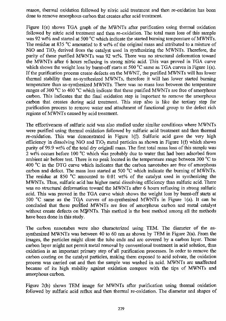
reason, thermal oxidation followed by nitric acid treatment and then re-oxidation has beendone to remove amorphous carbon that creates after acid treatment.
Figure I (e) shows TGA graph of the MWNTs after purification using thermal oxidationfollowed by nitric acid treatment and then re-oxidation. The total mass loss of this samplewas 92 wt"110 and started at 500°C which indicate the started burning temperature of MWNTs.The residue at 835°C amounted to 8 wt% of the original mass and attributed to a mixture ofNiO and TiOz derived from the catalyst used in synthesizing the MWNTs. Therefore, thepurity of these purified MWNTs was 92 wt%. There was no structural deformation towardthe MWNTs after 6 hours refluxing in strong nitric acid. This was proved in TGA curvewhich shows the weight loss by burnt-off starts at 500°C same as TGA curves in Figure I (a).If the purification process create defects on the MWNT, the purified MWNTs will has lowerthermal stability than as-synthesized MWNTs, therefore it will has lower started burningtemperature than as-synthesized MWNTs. There was no mass loss between the temperatureranges of 300°C to 400 °c which indicate that these purified MWNTs are free of amorphouscarbon. This indicates that the final oxidation step is important to remove the amorphouscarbon that creates during acid treatment. This step also is like the tertiary step forpurification process to remove water and attachment of functional group to the defect richregions of MWNTs caused by acid treatment.
The effectiveness of sulfuric acid was also studied under similar conditions where MWNTswere purified using thermal oxidation followed by sulfuric acid treatment and then thermalre-oxidation. This was demonstrated in Figure 1(t). Sulfuric acid gave the very highefficiency in dissolving NiO and TiOz metal particles as shown in Figure 1(t) which showspurity of 99.9 wt% of the total dry origimU mass. The first total mass loss of this sample was2 wt% occurs before 100°C which was probably due to water that had been adsorbed fromambient air before test. There is no peak located in the temperature range between 300 °c to400°C in the DTG curve which indicates that the carbon nanotubes are free of amorphouscarbon and defect. The mass loss started at 500°C which indicate the burning of MWNTs.The residue at 850°C amounted to 0.01 wt% of the catalyst used in synthesizing theMWNTs. Thus, sulfuric acid has higher metal dissolving efficiency than sulfuric acid. Therewas no structural deformation toward the MWNTs after 6 hours refluxing in strong sulfuricacid. This was proved in the TGA curve which shows the weight loss by burnt-off starts at500°C same as the TGA curves of as-synthesized MWNTs in Figure I(a). It can be
Jconcluded that these punfied MWNTs are free of amorphous carbon and metal catalystwithout create defects on MWNTs. This method is the best method among all the methodshave been done in this study.
The carbon nanotubes were also characterized using TEM. The diameter of the assynthesized MWNTs was between 40 to 60 nm as shown by TEM in Figure 2(a). From theimages, the particles might close the tube ends and are covered by a carbon layer. Thesecarbon layer might not permit metal removal by conventional treatment in acid solution, thusoxidation is an important primary step of'all purification processes. In order to remove thecarbon coating on the catalyst particles, making them exposed to acid solvate, the oxidationprocess was carried out and then the sample was washed in acid. MWNTs are unaffectedbecause of its high stability against oxidation compare with the tips of MWNTs andamorphous carbon.
Figure 2(b) shows TEM image for MWNTs after purification using thermal oxidationfollowed by sulfuric acid reflux and then thermal re-oxidation. The diameter and shapes of
279
carbon nanotubes remain the same as those in the image of the as-synthesized carbonnanotubes. Most of the metal particles were removed, same as the result obtained from TGA.The structure and the wall of MWNTs were not broken. All the tips were opened and metalsthat embedded inside the tubes were removed out. The dark spot on these figures is only dueto the superimposition of several carbon nanotubes. These results show that these MWNTshave high purity and good structure.
Figure 3(a) and (b) show low and high magnification of SEM images of as-synthesizedMWNTs, respectively. It was observed that the as-synthesized MWNTs contain not onlybundles of aligned carbon nanotubes but also significant amounts of metal particles entangledwith them. The bright spots in the images indicate the metal particles in the as-synthesizedMWNTs. Figure 3(c) and (d) show low and high magnification SEM image of purifiedMWNTs using thermal oxidation followed by sulfuric acid reflux and then thermal reoxidation, respectively. Figure 3(c) shows that there are free ofbright spot which indicate thatthe purified MWNTs are free ofmetal catalysts. It is again, same as the results obtained in theTGA analysis (Figure l(d)) and TEM image (Figure 2(b)) using thermal oxidation followedby sulfuric acid reflux and then thermal re-oxidation. Figure 3(d) clearly shows that the tipsof the carbon nanotube were opened. Once the tube caps are destroyed, the remaining part ofthe carbon nanotube essentially forms a perfect hexagonal network. Barring the tips, thecarbon nanotubes consist of a perfect hexagonal network free from strain and offer moreresistance to oxidation. This figure also indicates convincingly that the oxidation and acidreflux remove most of the impurities from the carbon nanotubes.
4.0 Conclusion
A multisteps purification process involving oxidation in air and acid washing successfullyremoved all metal catalysts and did not damage the structure of the carbon nanotubes.
Thermal oxidation followed by nitric acid treatment has higher efficiency than chemicaloxidation followed by nitric acid treatment due to chemical oxidation will create other metalparticles in MWNTs. Oxidation treatment can open the tips of MWNTs and expose the metalparticles inside the tube for further acid solvating. Acid treatment will create amorphouscarbon. Thermal oxidation after acid treatment helps to remove this amorphous carbon. Inthis study, sulfuric acid is the best acid to remove NiO and Ti02 metal catalysts in MWNTswithout damaging the structute of the carbon nanotubes. With this acid, as high as 99.9 wt%purity of MWNTs can be reached.
Acknowledgements
The authors acknowledge for the financial support provided by Academy of SciencesMalaysia under Scientific Advancement Grant Allocation (SAGA) (Project: A/C No.6053001) and Short Term Grant USM (Project: AlC No: 6035146).
280
References
[1] Chen, C.M., M.Y. Dai and J.G. Huang, Intennetallic catalyst for carbon nanotubes (CNTs) growth bythennal chemical vapor deposition method. 2006. Carbon 44: 1808-1820
[2] Hou, P.x., S. Bai, Q.H. Yang, C. Liu and H.M. Cheng. 2002. Multi-step purification of carbon nanotubes.Carbon 40: 81-85.
[3] Ko, C.J., C.Y. Lee, F.H. Ko, H.L. Chen and T.C. Chu. 2004. Highly efficient microwave-assistedpurification of multiwalled carbon nanotubes. Microelec. Eng. 73-74: 570-577.
[4] Fan Y.Y., A. Kaufmann, A Mukasyan and A. Vanna. 2006. Single- and multi-wall carbon nanotubesproduced using the floating catalyst method: Synthesis, purification and hydrogen up-take. Carbon(Accepted for published).
[5] Lee, J., H. Kim, S.J. Kahng, G. Kim, Y.W. Son, J. IHM, H. Kato, T. Wang, T. Okazaki, H. Shinohara andY. Kuk. 2002. Bandgap modulation of carbon nanotubes by encapsulated metallofullerenes. Nature 415:1005.
[6] Chen, C.M., M. Chen, F.e. Leu, S.Y. Hsu, S.C. Wang, S.C. Shi and e.F. Chen. 2004. Purification of multiwalled carbon nanotubes by microwave digestion method. Diam. ReI. Mater. 13: 1182-1186.
[7] Fahlbusch, S., S. Mazerolle, J.M. Breguet, A. Steinecker, J. Agnusd, R. P'erez and J. Michler. 2005Nanomanipulation in a scanning electron microscope. J ofMater. Proc. Tech. 167: 371-382.
[8] Maiyalagan, T., B. Viswanathan and V.V. Varadaraju 2005. Nitrogen containing carbon nanotubes assupports for Pt - Alternate anodes for fuel cell applications. Electrochem. Commun. 7: 905-912.
[9] Penza, M., M.A Tagliente, P. Aversa and G. Cassano, G. 2005. Organic-vapor detection using carbonnanotubes nanocomposite microacoustic sensors. Chem. Phys. Lett. 409:349-354.
[1O]Jeong, T., W.Y. Kim and YB. Hanh. 2001. A new purification method of single-walled carbon nanotubesusing H2S and O2 mixture gas, Chem. Phys. Lett. 344: 18-22.
[11] Wiltshire, J.G., L.J. Li, A.N. Khlobystov, C.J. Padbury, G.AD. Briggs and R.J. Nicholas. 2005. Magneticseparation of Fe catalyst from single-walled carbon nanotubes in an aqueous surfactant solution. Carbon43: 1151-1155
[12] Moon, J.M., K.H. An, Y.H., Lee, Y.S. Park, D.J. Bae and G.S. Park. 2001. High-yield purification processofsingle-walled carbon nanotubes. J. Phys. Cf].em. B 105: 5677-81.
[13] Strong, K.L., D.P. Anderson, K. Lafdi lllld J.N. Kuhn. 2003. Purification process for single-wall carbonnanotubes. Carbon 41: 1477-1488.
[14] Ko, F.H., C.Y. Lee, C.J. Ko and T.C. Chu, T.C., Purification of multi-walled carbon nanotubes throughmicrowave heating ofnitric acid in a closed vessel. Carbon 43: 727-733.
[15]Zein, S.H.S. and A.R. Mohamed. 2004. MnlNi/Ti02 catalyst for the production of hydrogen and carbonnanotubes from methane decomposition. Energy & Fuels 18: 1336-1345.
[16]Zein, S.H.S., A.R. Mohamed and P.S.T. Sai, P.S.T. 2004b. Kinetic studies on catalytic decomposition ofmethane to hydrogen and carbon over NilTi02 catalyst. Ind Eng. Chem. Res. 43: 4864 - 4870.
[17]Zein, S.H.S., AR. Mohamed, P.S.T. Sai and N.A.M. Zabidi. 2004a. Production of hydrogen and carbonnanotubes from methane. J. Ind. & Eng. Chem. 43: 4864 - 4870.
[18]Welham N.J. and J.S. Williams. 1998. Extended milling of graphite and activated carbon. Carbon 36(9):1309-15. I
[19]Shi, Z., Y. Lian, F. Liao,·X. Zhou, Z. Gu, Y. Zhang and S. Iijima. 1999. Purification of single-walledcarbon nanotubes. Solid State fjommun. 112: 35.
[20] Arepalli, S., P. Nikolaev, O. Gorelik, V.G. Hadjiev, W. Holmes, B. Files and L. Yowell. 2004. Protocol forthe characterization of single-wall carbon nanotube material quality. Carbon 42: 1783-1791.
[21]Li, H.J., L. Feng, L.H. Guan, Z.J. Shi and Z.N. Gu. 2004. Synthesis and purification ofsingle-walled carbonnanotubes in the cottonlike soot. Solid State Commun. 132: 219-224.
[22]Li, X., G. Yuan, A. Brown, A Westwood, R. Brydson and B. Rand. 2006. The removal of encapsulatedcatalyst particles from carbon nanotubes using molten salts. Carbon (Accepted for publication).
[23]Ramesh P., T. Okazaki, T. Sugai, J. Kimura, N. Kishi, K. Sato, Y. Ozeki and H. Shinohara. 2006.Purification and characterization of double-wail carbon nanotubes synthesized by catalytic chemical vapordeposition on mesoporous silica. Chem. Phys. Lett. 418: 408-412.
[24] Hernadi, K., A Siska, L. Thien-Nga, L. Forro and I. Kiricsi. 2001. Reactivity of different kinds of carbonduring oxidative purification of catalytically prepared carbon nanotubes. Solid State Ion. 141-142: 203209.
281
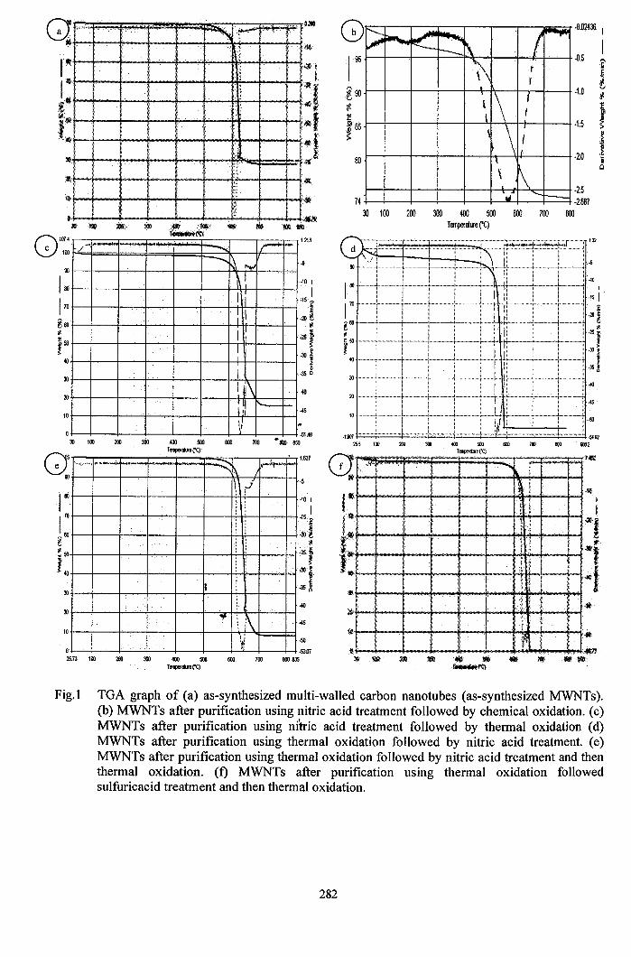
-0.5
-0.02436 I
I
-2.0
·1.0
-1.5
·10l-\:·ije..····-j.··-·······-F····-····iJ
~=b=b~4k;:;;;;;;t;d.sU2m ~ ~ ~ ~ ~ ~ ~2
'_....'re)
-+--¥--{.",""",,--+o.f'.~
.~ '* 3IlIl .~... .. l\lI!t1I<<<iD~f'I:l
--.:lIM..
.....I~,II"" .......
~~.....,~
\\ t
• t
\1\ ff
\:1
\ ~.~. "- r---.....
!Il t-··-·I
f···· i +-- + ..- ..-? l-+i-- ;. j_ .•__jj"s
-2.5~ ~
30 100 200 300 400 500 600 700 800Tempenille ('C)
30 1·······1········ .. "[.. :.. "1.. -: :.10
·t60125.5 100
10
100 I
.'51I.
10 1'+""""'" ·t-·········· j.-...........•..:........: 1··+··········· ··+·············+·······-··iJ :<.
.10!g!II -'-I4+~ ...._.."'i-.~_.+..-._-'-j-\ ~
~ ~;
:f9J I.)) i40 ' tI .~!
80
C0I~
·5
-15
1.213
·10 I
I.15~
j·20 t
~
•25 t·30 i_350
1.627
-51.48"tQl 850
./ ..... ....... .r"""" --~. "'".~I
I> :1II
II i\I
1'1Ii
o30 100 200 300
I00 ·10 ;
I'. 70 t---+--+~-+~-f---f-~---tC*-+~---t--t .,S?
~Eo .iolt ~
~ 50 •251t .JO.~
40 I30-I----+~_+~-+~-f---+~-+:-I--+-+-1-35 ~
~500 IiOO 700Temper...... ("C)Q " ,.~ i"-<-- ':::::l\ I
ill t---f---f---f---f---f---Ir'r--f+,--+-I <r-l ~
f\'W.4\V 100
10
Fig.l TGA graph of (a) as-synthesized multi-walled carbon nanotubes (as-synthesized MWNTs).(b) MWNTs after purification using nitric acid treatment followed by chemical oxidation. (c)MWNTs after purification using nitric acid treatment followed by thermal oxidation (d)MWNTs after purification using thermal oxidation followed by nitric acid treatment. (e)MWNTs after purification using thermal oxidation followed by nitric acid treatment and thenthermal oxidation. (f) MWNTs after purification using thermal oxidation followedsulfuricacid treatment and then thermal oxidation.
282
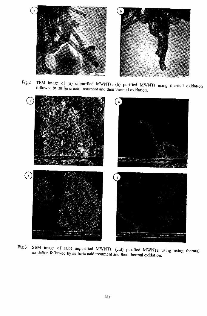
I .
Fig.2 TEM image of (a) unpurified MWNTs. (b) purified MWNTs using thermal oxidationfollowed by sulfuric acid treatment and then thermal oxidation.
Q
Fig.3 SEM image of (a,b) unpurified MWNTs. (c,d) purified MWNTs using using thermaloxidation followed by sulfuric acid treatment and then thermal oxidation.
283
· .
SYNTHESIS, CHARACTERIZATIONAND CAPACITANCE MEASUREMENT OFMANGANESE OXIDE I MULTI-WALLED
CARBON NANOTUBE NANOCOMPOSITES
NAME
SUPERVISOR
UNlVERSITI SAINS MALAYSIA
SCHOOL OF CHEMICAL ENGINEERINGENGINEERING CAMPUS
UNlVERSITI SAINS MALAYSIASERIAMPANGAN
14300 NIBONG TEBALSEBERANG PERAI SELATAN
PULAU PINANG
EKe 499 - FINAL YEAR PROJECT
ABDUL MUNIR BIN MOHO. YAAKOB (73093)
DR SHARIF HUSSEIN SHARIF ZEIN,,
I
SYNTHESIS, CHARACTERIZATIONAND CAPACITANCE MEASUREMENT OFMANGANESE OXIDE 1MULTI-WALLED
CARBONNANOTUBENANOCOMWOSITES
ABDUL MUNIR BIN MOHD YAAKOB,.
.. 73093
.,
UNIVERSITY SCffiNCE OF MALAYSIA2006/2007
"
ACKNOWLEDGEMENT
I would like to express my genuine appreciation and gratitude to all the people
who involve directly or indirectly in this thesis.
Special thanks to my project supervisor, Dr Sharif Hussein Sharif Zein for his
encouragements, advices and guidance during this research. His commitment, experience
and knowledge have helped me a lot to finish up my research and write this thesis.
Secondly, I would like to thank Prof. Kamarulazizi Ibrahim (School of Physics),
Assoc. Prof. Azizan Aziz (School ofMaterials and Mineral Resources Engineering), and
Dr Dahaman Ishak (School of Electrical and Electronic Engineering) for their ideas and
guidance. I would like also to express my appreciation to those technicians that helped
me a lot during my research especially Mrs. Latifah Abd. Latif (School of Chemical
Engineering), Mr. R Patchamuthu (School of Biological Sciences), Mr. Mokhtar Sabdin
and Mr. Abdul Jamil Yusuff (School ofPhysics).
Lastly, thank you to my family and friends for their support, encouragement and
helps which helped me to solve all the problems faced during my research and finallyI
completed my thesis.
Thank. you very much to all ofyou.
,,
i1
I Ii!~
Ii!!I,~,;!l,~
UNIVERSITI SAINS MALAYSIASCHOOL OF CHEMICAL ENGINEERING
ENGINEERING CAMPUS
PURIFICATION OF.CARBON NANOTUBESPRODUCED FROM CATALYTIC
DECOMPOSITION OF METHANE
..,
f III
!I!iI
.,
. I
April 2006
AIDAWATI AZ·ll.NBINTIISMAILMatrie No.: 65586
··~----------------_-.... I
I
. !. I
I,IIIII
ACKNOWLEDGEMENT
First ofall, I would thank Allah the Almighty for the strength and all His guidance.
With His blessings, I finally completed this thesis. I would like to express my genuine
appreciation to the entire person upon supports, help and assists during carried out my Final
Year Project throughout this semester. Here, thousand words to thank you is littered from
me toward upon their kindness dedication to me.
Special thanks to my supervisOr, Dr Sharif Hussein Sharif Zein for the enonnous
time and effort he spent guiding and assisting me through this thesis process. I also would
like to acknowledge my gratitude to Dean of School of Chemical Engineering, Professor
Madya Abdul Latif bin Ahmad for his permission in usmg all the facilities and equipment
for my project.
.Also, I would like to express to .those are indirectly contributed in this project, your
contribution are highly appreciatesl. You make me more confidence to face the difficulties
during the project progression. Sincere thanks to postgraduate student, Kong Bee Hong and
all technicians and stafffor their cooperation and wannest helping hand.
Finally, I would life show my deeply thanks to all my loving family and friends that
support behind me and giv~me advice and suggestion in solving the problem during my
Final Year Project. There are also others that I w~uld like to thank for their friendship,
kindness and understanding during my time,in USM.
,,
ii

ACKNQWLEDGEMENT
First of aU, I would like to express my utmost gratitude and appreciation to my
supervisor. Dr. Sharif Hussein Sharif Zein, who is willing to sacrifice his time to guide
me in completing this interim report. Besides, thank you so much to Dr. Zuhairi
Abdullah as the coordinator, non-academic staffs and technicians, who helps me a lot in
completing my lab work. Thanks for your commitnient.
Special thanks goes to my parents and my family for their guidance and support~.
Th8nks for your advice and encouragement when I was greatly required to finish this
project.
I also would like to thank to my "entire friend who have help and give their wann
cooperation and finally, I want -to appreciate all the people who involve directly or
indirectly in helping me to complete this interim report.
This Final Year Project gave me training to write a fonnal report and gain knowledge
from the process o~ completing my project. Thanks again to all the people mentioned
above for making my a;tachment here a memorable and educational one.
Thank you,
Nor Hasridah bt Abu Hassan,,
\
- .... -----_..._-.--~

ACKNOWLEDGEMENT
I wish to extend my sin(fere gratitud~ and appreciation to the people who made this
thesis possible.
Firstly, I would like to express my special thanks and gratitude to my project
supervisor, Dr Sharif Hussien Sharif Zein for his untiring guidance and advice. He has
been both my teacher and mentor throughout the project. His experience and knowledge.
has helped me a lot in carrying out my work.
.-My gratitude goes to Chai.Siang Piao, PHD post graduate student and Kong Bee.
Hong,.master post graduate student. I wish to thank them for their unrelenting help and
support. I also wish to thank Chee Anny and Aidawati Azlin binti Ismail, fmal year"
student for their help.
.... ",.,
Lastly, special appreciation goes to my friends and family, which encouraged
me throughoutthe process of.getting the report completed. Their support and love helped
me tIiroUgh-when things seem difficult. \,
..
---"",-' ..
. '
SYNTHESIS AND CHARACTERIZATION OFPOLVPROPYLENEIMULI-WALLED NANOTUBES
NANOCOMPOSITES
CHANKOKSAN
,,
2007
ACKNOWLEDGEMENT
First ofall, I would like to express my greatest gratitude and sincere appreciation to
Dr. Sharif Hussein who is my Final Year Project supervisor for his precious advices,
guidance, commitment, and support and ideas contribution to complete this project
Not to fOIXet Dr. Lee Keat TIong who has been giving lots ofencouragement, advices,
time to prolong the-scope ofthis project
My special appreciation also goes to Mr. Ansari, lecturer of Asian Institute of
Medicine Science and Technology (AIMST) who had been guided me all the time of
the project To Mr. Faizal from school of Polymer Engineering, Universiti Sains
Malaysia, and Mr. Kong Poh Quai,. lab supervisor of school of Physics, Universiti
Sains Malaysia for their guidance and help during the analysis.
I would like to express my deepest love and gratitude to my parent and my siblings
for their endless.support and encouragement~ but not least to my ftends for all the
thard time we have been through.
I beg those who are not named·owning to lack ofknowledge or to error to pardon me
in advance.,,
PURIFICATION OF MULTI-WALLED CARBONNANOTUBES PRODUCED FROM CATALYTIC
DECOMPOSITION OF METHANE USINGDIFFERENT PAPRAMETERS
I
UMI ~ATRAHBINTI ABDOL KARIM
•,
2007
COATING OF CARBON NANOTUBES WITH Ti02 AND
ITS CHARACTERIZATION
TAN AI NEE
.,UNIVERSITI SAINS MALAYSIA
2007

..
ACKNOWLEDGEMENT
Thanks to god, finally I success to complete my fmal year project after a few
months working on it. During this time, sometime I face a hard time but thanks to the
people around me who give me support. I also had a sweet time during this time. Here I
would like to acknowledge to people involve in this project.
First qf all, SPecial thanks to my supervisor Dr. Sharif Husein Sharif zein, who
give me guidance, support and advice during this project. Who is always around when I
have problem with this project. I'm really happy working with you.
Secondly, I want to thanks to altthe technicians, Mrs. Latif~ Mr Faiza and Mr..Ariff which involve in this project. Under their help and advice I can do my experiment
smoothly. I also would like to express my thanks to Mr. Rashid, Mr Ahmad and Mr.
Mutu for the analysis ofmy sample. :
. To my friend arJund me, who share my hard time and sweet time together.
Thanks for your support.
. Lastly, to my.parent and sibling at home time who always with me, support me
from behind and always pray for my su~ess and haPpiness. Thank you very much and I
love you.
1
ACKNOWLEDGEMENT
First of all, I would like to seize this chance to show my utmost gratitude and
appreciation to my final year project supervisor, Dr. Sharif Hussein Sharif Zein for
the enormous time and great effect he had spent to guide and assist me since the
starting ofmy fmal year project until the end ofmy thesis writing.
On top of that, I am deeply grateful to all of the staffs and technicians of
School of Chemical Engineering, Universiti Sains Malaysia for their assistance and
cooperation in completing my fmal year project.
Besides, I would like to take this chance to thank my family for their
encouragement, support and understanding throughout my final year project period.
Last but not least, I would lik~ to thank all the people involved directly or.
indirectly throughout the completion'9fmy final year project.
I
i,