aw139 pwpt6 tr bas lowres
TRANSCRIPT

7/22/2019 Aw139 Pwpt6 Tr Bas Lowres
http://slidepdf.com/reader/full/aw139-pwpt6-tr-bas-lowres 1/1016

7/22/2019 Aw139 Pwpt6 Tr Bas Lowres
http://slidepdf.com/reader/full/aw139-pwpt6-tr-bas-lowres 2/1016
7/22/2019 Aw139 Pwpt6 Tr Bas Lowres
http://slidepdf.com/reader/full/aw139-pwpt6-tr-bas-lowres 3/1016

7/22/2019 Aw139 Pwpt6 Tr Bas Lowres
http://slidepdf.com/reader/full/aw139-pwpt6-tr-bas-lowres 4/1016
7/22/2019 Aw139 Pwpt6 Tr Bas Lowres
http://slidepdf.com/reader/full/aw139-pwpt6-tr-bas-lowres 5/1016

7/22/2019 Aw139 Pwpt6 Tr Bas Lowres
http://slidepdf.com/reader/full/aw139-pwpt6-tr-bas-lowres 6/1016
7/22/2019 Aw139 Pwpt6 Tr Bas Lowres
http://slidepdf.com/reader/full/aw139-pwpt6-tr-bas-lowres 7/1016
7/22/2019 Aw139 Pwpt6 Tr Bas Lowres
http://slidepdf.com/reader/full/aw139-pwpt6-tr-bas-lowres 8/1016
7/22/2019 Aw139 Pwpt6 Tr Bas Lowres
http://slidepdf.com/reader/full/aw139-pwpt6-tr-bas-lowres 9/1016

7/22/2019 Aw139 Pwpt6 Tr Bas Lowres
http://slidepdf.com/reader/full/aw139-pwpt6-tr-bas-lowres 10/1016
7/22/2019 Aw139 Pwpt6 Tr Bas Lowres
http://slidepdf.com/reader/full/aw139-pwpt6-tr-bas-lowres 11/1016

7/22/2019 Aw139 Pwpt6 Tr Bas Lowres
http://slidepdf.com/reader/full/aw139-pwpt6-tr-bas-lowres 12/1016
7/22/2019 Aw139 Pwpt6 Tr Bas Lowres
http://slidepdf.com/reader/full/aw139-pwpt6-tr-bas-lowres 13/1016
7/22/2019 Aw139 Pwpt6 Tr Bas Lowres
http://slidepdf.com/reader/full/aw139-pwpt6-tr-bas-lowres 14/1016
7/22/2019 Aw139 Pwpt6 Tr Bas Lowres
http://slidepdf.com/reader/full/aw139-pwpt6-tr-bas-lowres 15/1016
7/22/2019 Aw139 Pwpt6 Tr Bas Lowres
http://slidepdf.com/reader/full/aw139-pwpt6-tr-bas-lowres 16/1016
7/22/2019 Aw139 Pwpt6 Tr Bas Lowres
http://slidepdf.com/reader/full/aw139-pwpt6-tr-bas-lowres 17/1016
7/22/2019 Aw139 Pwpt6 Tr Bas Lowres
http://slidepdf.com/reader/full/aw139-pwpt6-tr-bas-lowres 18/1016
7/22/2019 Aw139 Pwpt6 Tr Bas Lowres
http://slidepdf.com/reader/full/aw139-pwpt6-tr-bas-lowres 19/1016
7/22/2019 Aw139 Pwpt6 Tr Bas Lowres
http://slidepdf.com/reader/full/aw139-pwpt6-tr-bas-lowres 20/1016
7/22/2019 Aw139 Pwpt6 Tr Bas Lowres
http://slidepdf.com/reader/full/aw139-pwpt6-tr-bas-lowres 21/1016
7/22/2019 Aw139 Pwpt6 Tr Bas Lowres
http://slidepdf.com/reader/full/aw139-pwpt6-tr-bas-lowres 22/1016
7/22/2019 Aw139 Pwpt6 Tr Bas Lowres
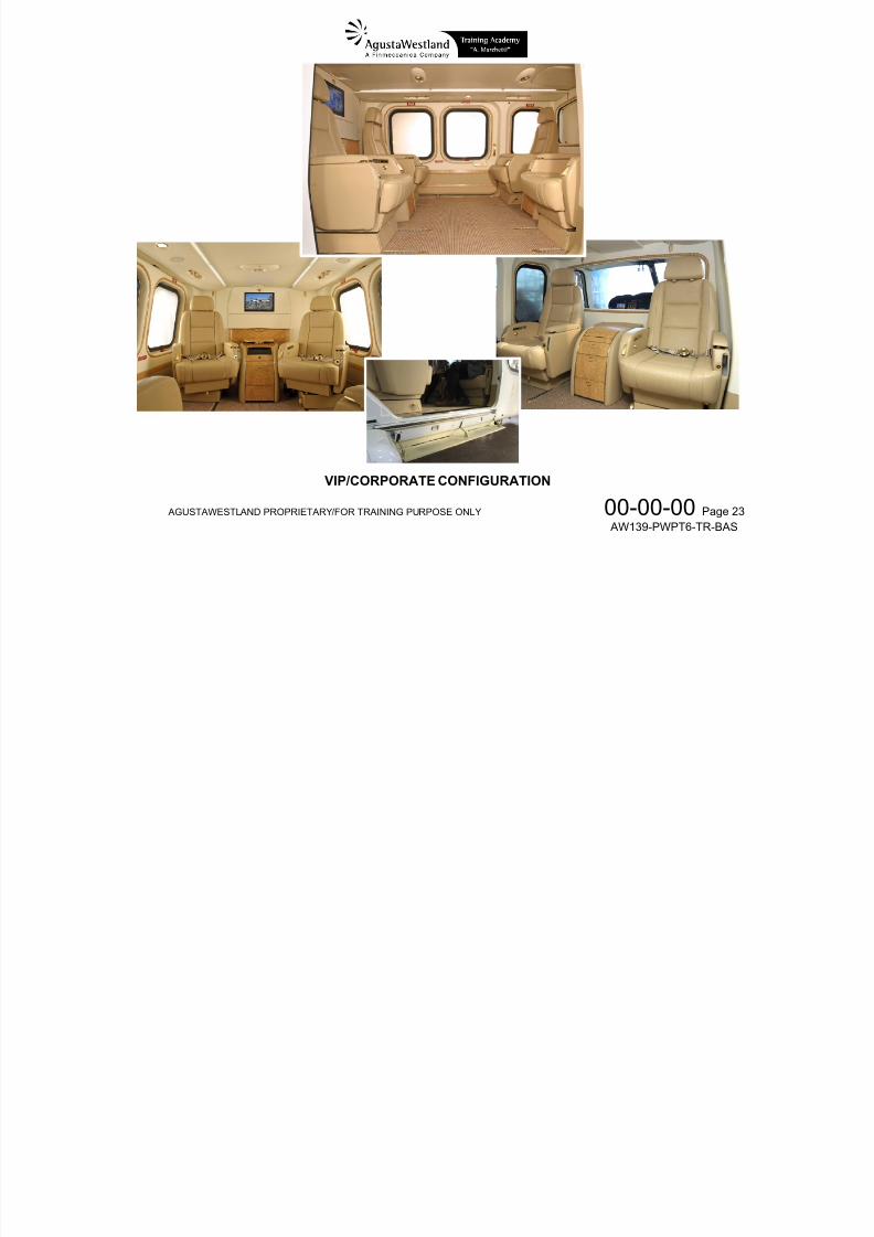
http://slidepdf.com/reader/full/aw139-pwpt6-tr-bas-lowres 23/1016
7/22/2019 Aw139 Pwpt6 Tr Bas Lowres
http://slidepdf.com/reader/full/aw139-pwpt6-tr-bas-lowres 24/1016
7/22/2019 Aw139 Pwpt6 Tr Bas Lowres
http://slidepdf.com/reader/full/aw139-pwpt6-tr-bas-lowres 25/1016
7/22/2019 Aw139 Pwpt6 Tr Bas Lowres
http://slidepdf.com/reader/full/aw139-pwpt6-tr-bas-lowres 26/1016
7/22/2019 Aw139 Pwpt6 Tr Bas Lowres
http://slidepdf.com/reader/full/aw139-pwpt6-tr-bas-lowres 27/1016
7/22/2019 Aw139 Pwpt6 Tr Bas Lowres
http://slidepdf.com/reader/full/aw139-pwpt6-tr-bas-lowres 28/1016
7/22/2019 Aw139 Pwpt6 Tr Bas Lowres
http://slidepdf.com/reader/full/aw139-pwpt6-tr-bas-lowres 29/1016
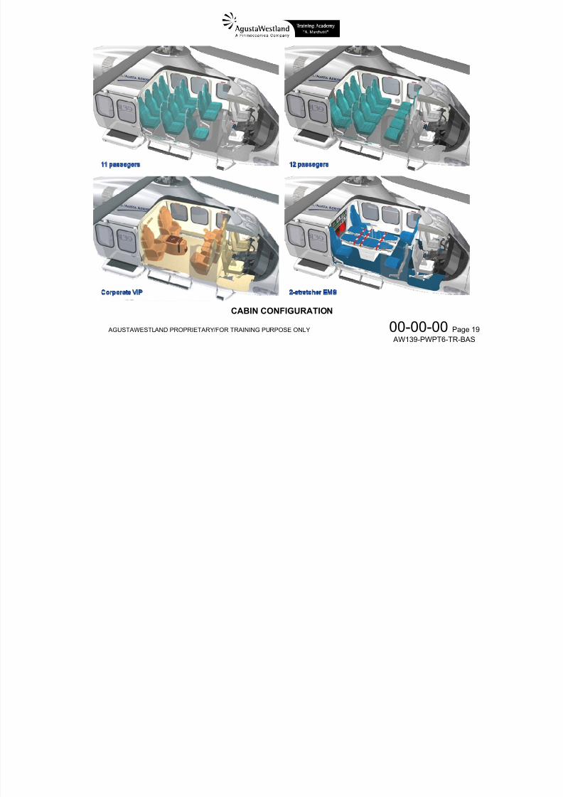
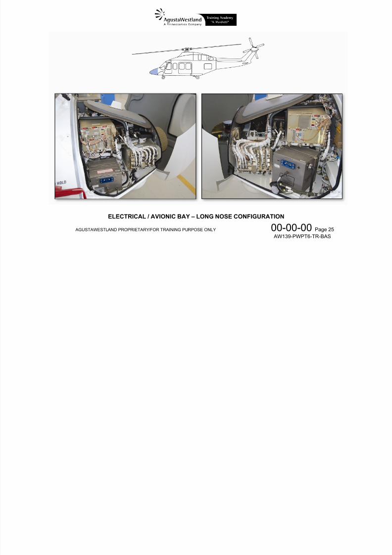
AGUSTAWESTLAND PROPRIETARY/FOR TRAINING PURPOSE ONLY 00-00-00 Page 25 AW139-PWPT6-TR-BAS
ELECTRICAL / AVIONIC BAY – LONG NOSE CONFIGURATION
7/22/2019 Aw139 Pwpt6 Tr Bas Lowres
http://slidepdf.com/reader/full/aw139-pwpt6-tr-bas-lowres 30/1016
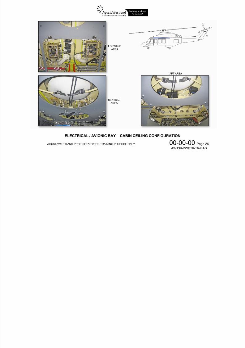
AGUSTAWESTLAND PROPRIETARY/FOR TRAINING PURPOSE ONLY 00-00-00 Page 26 AW139-PWPT6-TR-BAS
ELECTRICAL / AVIONIC BAY – CABIN CEILING CONFIGURATION
7/22/2019 Aw139 Pwpt6 Tr Bas Lowres
http://slidepdf.com/reader/full/aw139-pwpt6-tr-bas-lowres 31/1016
AGUSTAWESTLAND PROPRIETARY/FOR TRAINING PURPOSE ONLY 00-00-00 Page 27 AW139-PWPT6-TR-BAS
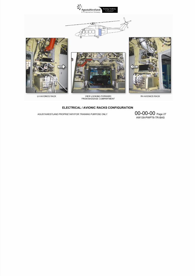
ELECTRICAL / AVIONIC RACKS CONFIGURATION
7/22/2019 Aw139 Pwpt6 Tr Bas Lowres
http://slidepdf.com/reader/full/aw139-pwpt6-tr-bas-lowres 32/1016
AGUSTAWESTLAND PROPRIETARY/FOR TRAINING PURPOSE ONLY 00-00-00 Page 28 AW139-PWPT6-TR-BAS
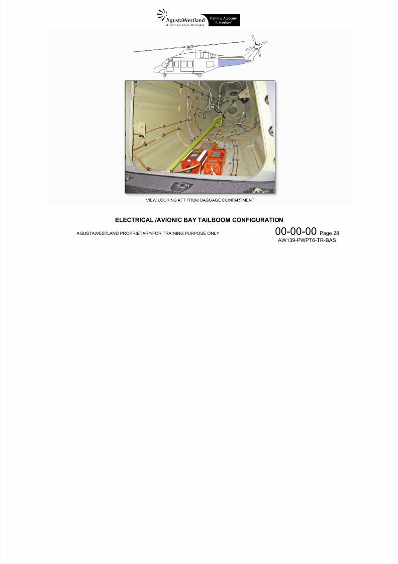
ELECTRICAL /AVIONIC BAY TAILBOOM CONFIGURATION
7/22/2019 Aw139 Pwpt6 Tr Bas Lowres
http://slidepdf.com/reader/full/aw139-pwpt6-tr-bas-lowres 33/1016
AGUSTAWESTLAND PROPRIETARY/FOR TRAINING PURPOSE ONLY 00-00-00 Page 29 AW139-PWPT6-TR-BAS
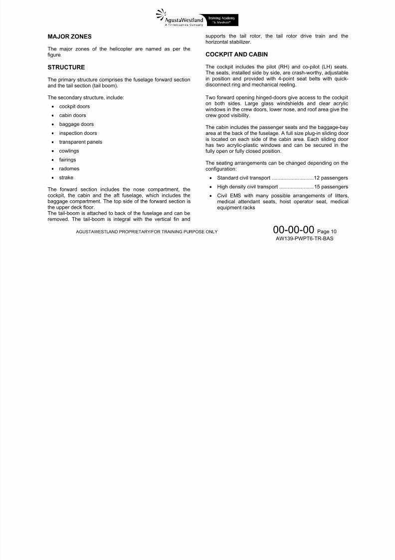
SYSTEMS OVERVIEW
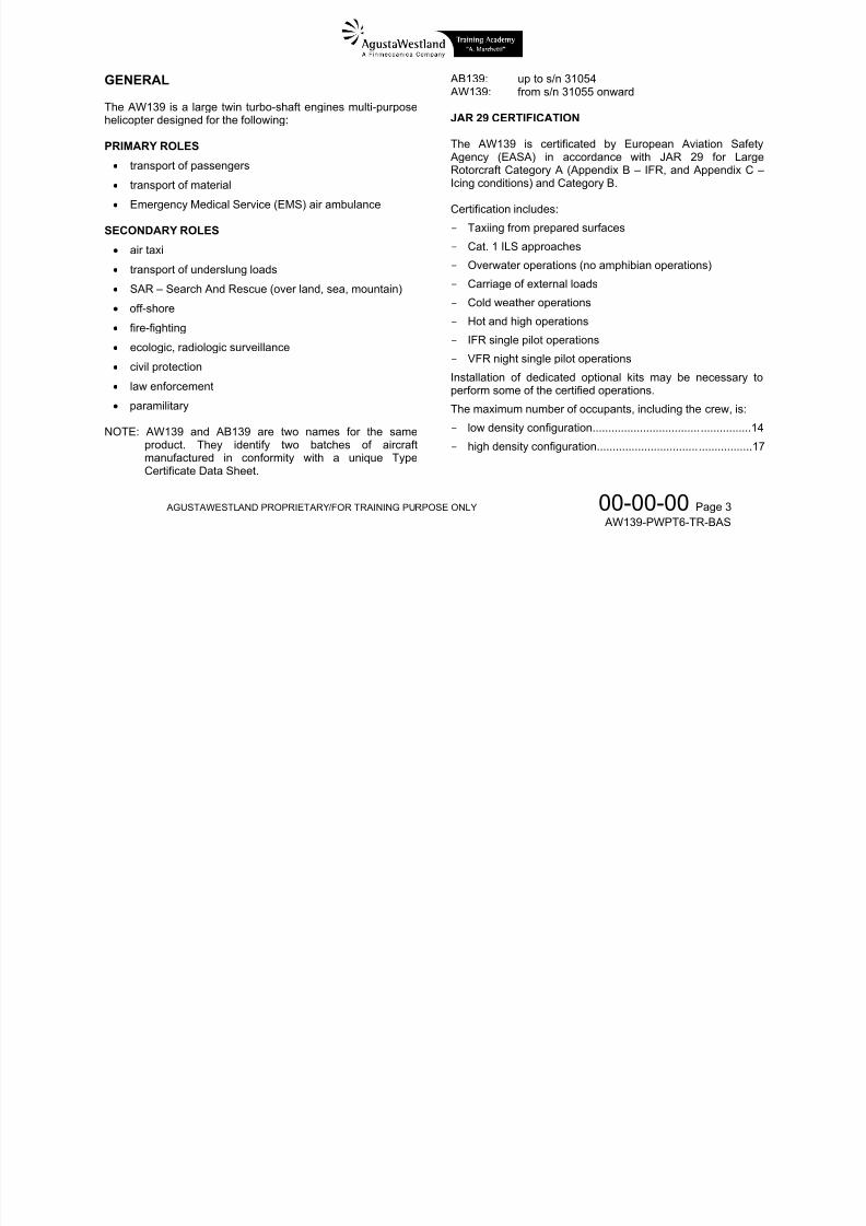
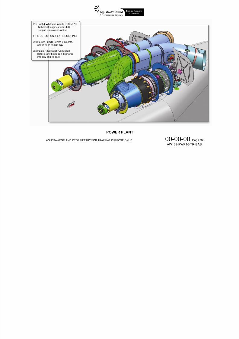
POWER PLANT
The power plant comprises the engines and relatedinstallation, fire detection and extinguishing system.
Engines
The helicopter is powered by two PT6C-67C turboshaftengines. Each engine is installed in a separated fireproof areaabove the cabin roof and supplies power to the drive systemby means of a rotating shaft. The engines are connected tothe airframe by means of two attachment points on the enginebody and to the main gearbox by means of a tube and agimbal joint.
Air is supplied to the engine via individual, side facing airinlets. The engines are started by a DC starter-generator.Engine control is achieved via a control panel located in thecockpit and manual back-up of the engine control via push-pull cables.The engines are provided with torque sensing and matching.
Fire detection and extinguishing
The fire detection system consists of a continuous wiredetector installed in the powerplant fire zones, routed in a waythat allows coverage of all critical areas.The fire extinguishing system consists of directional flowvalves which allow discharging the contents of one bottlewhile sealing the connection to the other bottle and the
subsequent discharge of the second bottle in the same bay ifrequired.
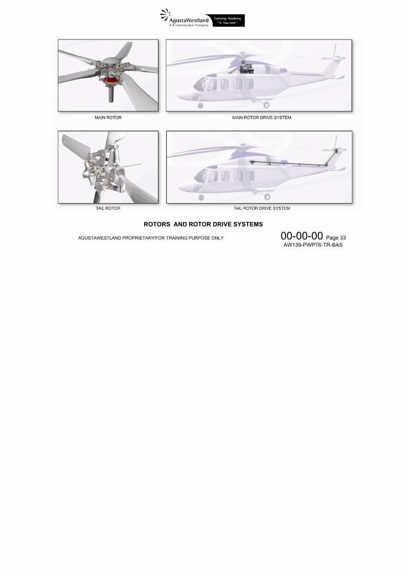
DRIVE SYSTEM
The drive system consists of the Main Rotor Drive Systemand the Tail Rotor Drive System.
Main Rotor Drive System
The Main Rotor Drive System mainly consists of the MainGearbox (MGB) that is mounted on the roof of the cabin bymeans of four struts and an anti-torque device.The MGB has three stages of reduction and includes aduplicated oil lubrication system. It provides the attachmentpoints for the rotor brake coaxial with the tail rotor driveoutput.
The MGB drives three hydraulic pumps and otheraccessories.
Tail Rotor Drive System
The tail rotor drive system consists of three drive shaft drivenby the MGB, the Intermediate Gearbox IGB and the TailGearbox TGB oil splash lubricated.
ROTORS
The rotor system consists of a Main Rotor (MR) and a tailRotor (TR).The main rotor is a five blades, fully articulated rotor.The tail rotor is a four blades, fully articulated rotor.
7/22/2019 Aw139 Pwpt6 Tr Bas Lowres
http://slidepdf.com/reader/full/aw139-pwpt6-tr-bas-lowres 34/1016
7/22/2019 Aw139 Pwpt6 Tr Bas Lowres
http://slidepdf.com/reader/full/aw139-pwpt6-tr-bas-lowres 35/1016
AGUSTAWESTLAND PROPRIETARY/FOR TRAINING PURPOSE ONLY 00-00-00 Page 31 AW139-PWPT6-TR-BAS
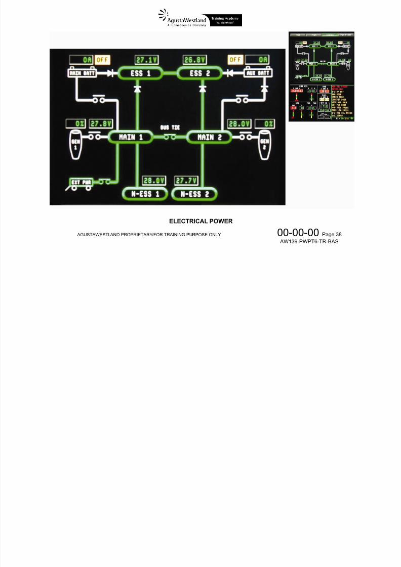
Essential (ESS) and Non-Essential (NON ESS) busses.Power from a DC external power source can also be
connected to the aircraft busses.
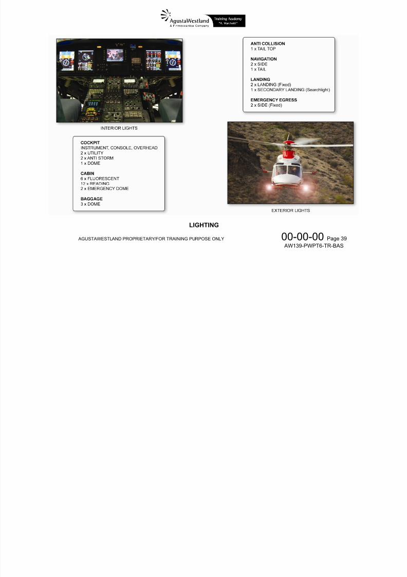
LIGHTING
The lighting system includes interior and exterior lights.The interior lights supply instruments lighting, panels lighting,overhead panels lighting and cockpit utility lighting.
The exterior lights include anti collision lights, position lights,navigation lights and landing lights.NVG compatibility is provided as an option.
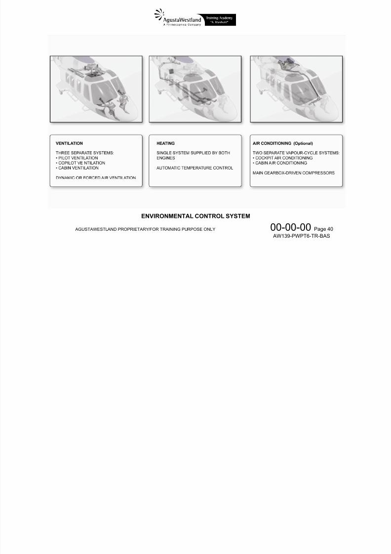
COCKPIT AND CABIN VENTILATION SYSTEM
The ventilation system consists of two separate sub-systemsfor cockpit and cabin ventilation; heating and cooling systemsare provided as optional kits.
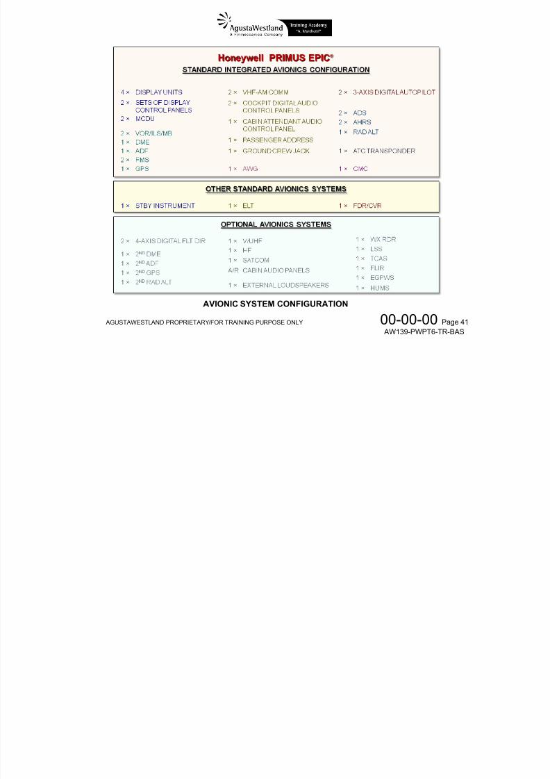
AVIONICS
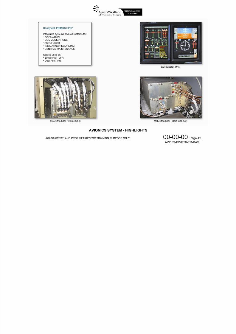
The PRIMUS EPIC ® system is an integrated avionics systemthat includes the following sub-systems necessary to operate:
Auto-Pilot
Flight Management System
Communications
Indicating and Recording Systems
Aural Warning Generator
Navigation
Crew Alerting System
Central Maintenance Systems (CMS)
The PRIMUS EPIC ® system is integrated into: – two Modular Avionics Units (MAU) – four flat panel color LCD Display Units (DU) to show
data in the cockpit – two Modular Radio Cabinets (MRC) that include the
following radios:
VHF-COMM
VOR/ILS
ADF
DME
Transponder (XPDR)
The MAUs, the DUs and the MRCs are directly connected toeach other via a bi-directional digital data bus named AvionicStandard Communication Bus-D (ASCB-D).
A LAN digital bus also interconnects the same units formaintenance purposes.
7/22/2019 Aw139 Pwpt6 Tr Bas Lowres
http://slidepdf.com/reader/full/aw139-pwpt6-tr-bas-lowres 36/1016
AGUSTAWESTLAND PROPRIETARY/FOR TRAINING PURPOSE ONLY 00-00-00 Page 32 AW139-PWPT6-TR-BAS
POWER PLANT

7/22/2019 Aw139 Pwpt6 Tr Bas Lowres
http://slidepdf.com/reader/full/aw139-pwpt6-tr-bas-lowres 37/1016
AGUSTAWESTLAND PROPRIETARY/FOR TRAINING PURPOSE ONLY 00-00-00 Page 33 AW139-PWPT6-TR-BAS
ROTORS AND ROTOR DRIVE SYSTEMS

7/22/2019 Aw139 Pwpt6 Tr Bas Lowres
http://slidepdf.com/reader/full/aw139-pwpt6-tr-bas-lowres 38/1016
AGUSTAWESTLAND PROPRIETARY/FOR TRAINING PURPOSE ONLY 00-00-00 Page 34 AW139-PWPT6-TR-BAS
FLIGHT CONTROLS
7/22/2019 Aw139 Pwpt6 Tr Bas Lowres
http://slidepdf.com/reader/full/aw139-pwpt6-tr-bas-lowres 39/1016
AGUSTAWESTLAND PROPRIETARY/FOR TRAINING PURPOSE ONLY 00-00-00 Page 35 AW139-PWPT6-TR-BAS
HYDRAULIC POWER
7/22/2019 Aw139 Pwpt6 Tr Bas Lowres
http://slidepdf.com/reader/full/aw139-pwpt6-tr-bas-lowres 40/1016
AGUSTAWESTLAND PROPRIETARY/FOR TRAINING PURPOSE ONLY 00-00-00 Page 36 AW139-PWPT6-TR-BAS
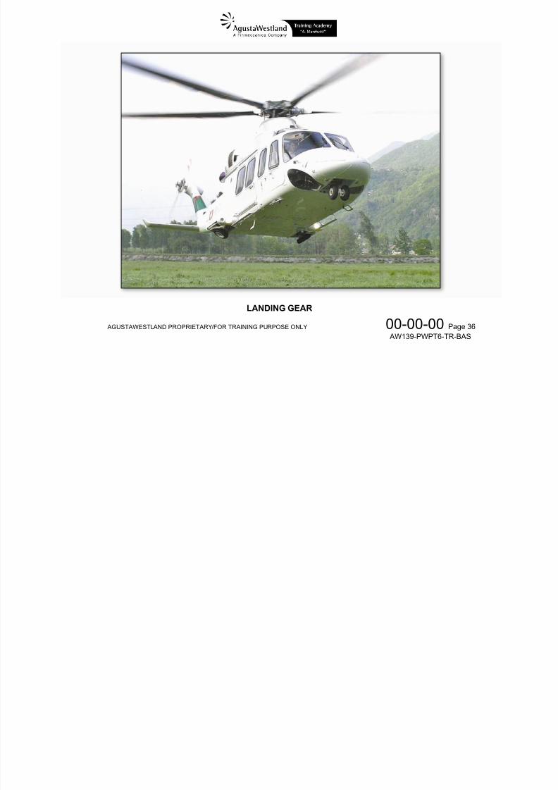
LANDING GEAR
7/22/2019 Aw139 Pwpt6 Tr Bas Lowres
http://slidepdf.com/reader/full/aw139-pwpt6-tr-bas-lowres 41/1016
AGUSTAWESTLAND PROPRIETARY/FOR TRAINING PURPOSE ONLY 00-00-00 Page 37 AW139-PWPT6-TR-BAS
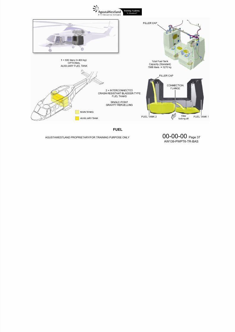
FUEL
7/22/2019 Aw139 Pwpt6 Tr Bas Lowres
http://slidepdf.com/reader/full/aw139-pwpt6-tr-bas-lowres 42/1016
AGUSTAWESTLAND PROPRIETARY/FOR TRAINING PURPOSE ONLY 00-00-00 Page 38 AW139-PWPT6-TR-BAS
ELECTRICAL POWER
7/22/2019 Aw139 Pwpt6 Tr Bas Lowres
http://slidepdf.com/reader/full/aw139-pwpt6-tr-bas-lowres 43/1016
AGUSTAWESTLAND PROPRIETARY/FOR TRAINING PURPOSE ONLY 00-00-00 Page 39 AW139-PWPT6-TR-BAS
LIGHTING
7/22/2019 Aw139 Pwpt6 Tr Bas Lowres
http://slidepdf.com/reader/full/aw139-pwpt6-tr-bas-lowres 44/1016
AGUSTAWESTLAND PROPRIETARY/FOR TRAINING PURPOSE ONLY 00-00-00 Page 40 AW139-PWPT6-TR-BAS
ENVIRONMENTAL CONTROL SYSTEM
7/22/2019 Aw139 Pwpt6 Tr Bas Lowres
http://slidepdf.com/reader/full/aw139-pwpt6-tr-bas-lowres 45/1016
AGUSTAWESTLAND PROPRIETARY/FOR TRAINING PURPOSE ONLY 00-00-00 Page 41 AW139-PWPT6-TR-BAS
AVIONIC SYSTEM CONFIGURATION
7/22/2019 Aw139 Pwpt6 Tr Bas Lowres
http://slidepdf.com/reader/full/aw139-pwpt6-tr-bas-lowres 46/1016
AGUSTAWESTLAND PROPRIETARY/FOR TRAINING PURPOSE ONLY 00-00-00 Page 42 AW139-PWPT6-TR-BAS
AVIONICS SYSTEM - HIGHLIGHTS
7/22/2019 Aw139 Pwpt6 Tr Bas Lowres
http://slidepdf.com/reader/full/aw139-pwpt6-tr-bas-lowres 47/1016
AGUSTAWESTLAND PROPRIETARY/FOR TRAINING PURPOSE ONLY 00-03-00 Page 1 AW139-PWPT6-TR-BAS
CHAPTER
00AIR VEHICLE GENERAL
SECTION 03 – COCKPIT LAYOUT
7/22/2019 Aw139 Pwpt6 Tr Bas Lowres
http://slidepdf.com/reader/full/aw139-pwpt6-tr-bas-lowres 48/1016
AGUSTAWESTLAND PROPRIETARY/FOR TRAINING PURPOSE ONLY 00-03-00 Page 2 AW139-PWPT6-TR-BAS
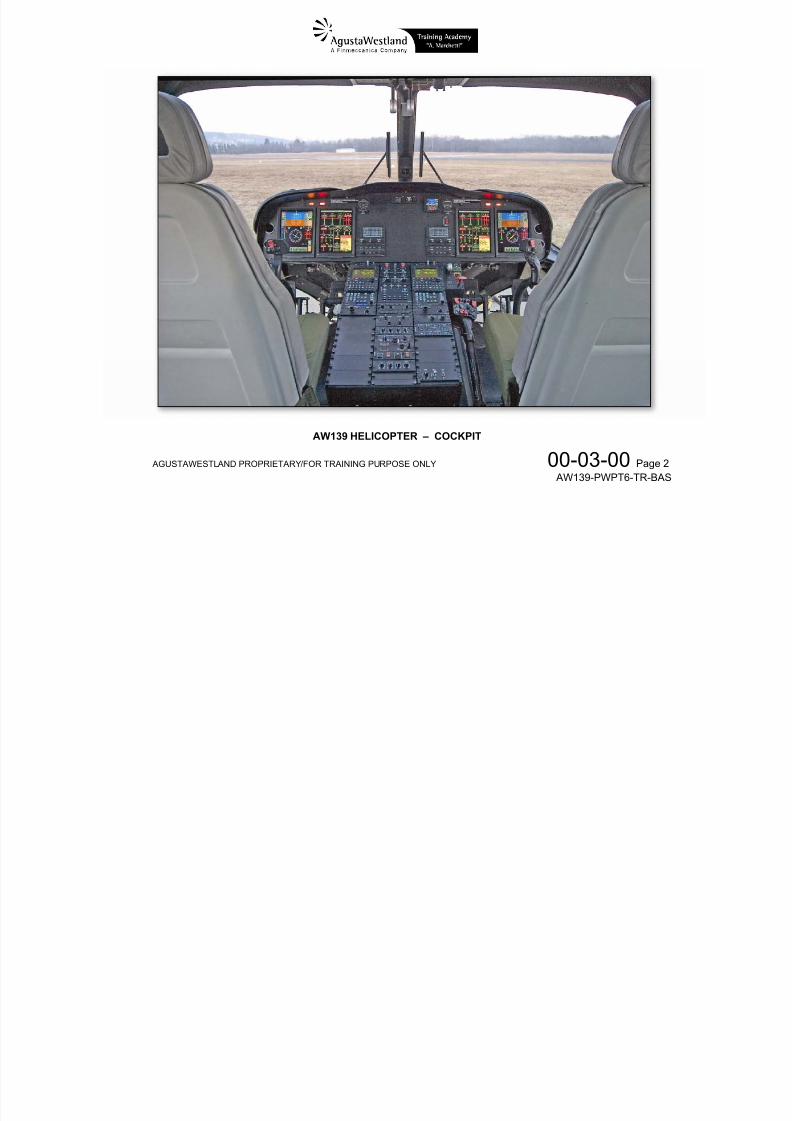
AW139 HELICOPTER – COCKPIT
7/22/2019 Aw139 Pwpt6 Tr Bas Lowres
http://slidepdf.com/reader/full/aw139-pwpt6-tr-bas-lowres 49/1016
AGUSTAWESTLAND PROPRIETARY/FOR TRAINING PURPOSE ONLY 00-03-00 Page 3 AW139-PWPT6-TR-BAS
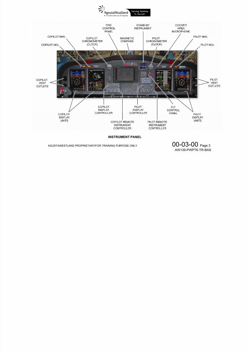
INSTRUMENT PANEL
7/22/2019 Aw139 Pwpt6 Tr Bas Lowres
http://slidepdf.com/reader/full/aw139-pwpt6-tr-bas-lowres 50/1016
AGUSTAWESTLAND PROPRIETARY/FOR TRAINING PURPOSE ONLY 00-03-00 Page 4 AW139-PWPT6-TR-BAS
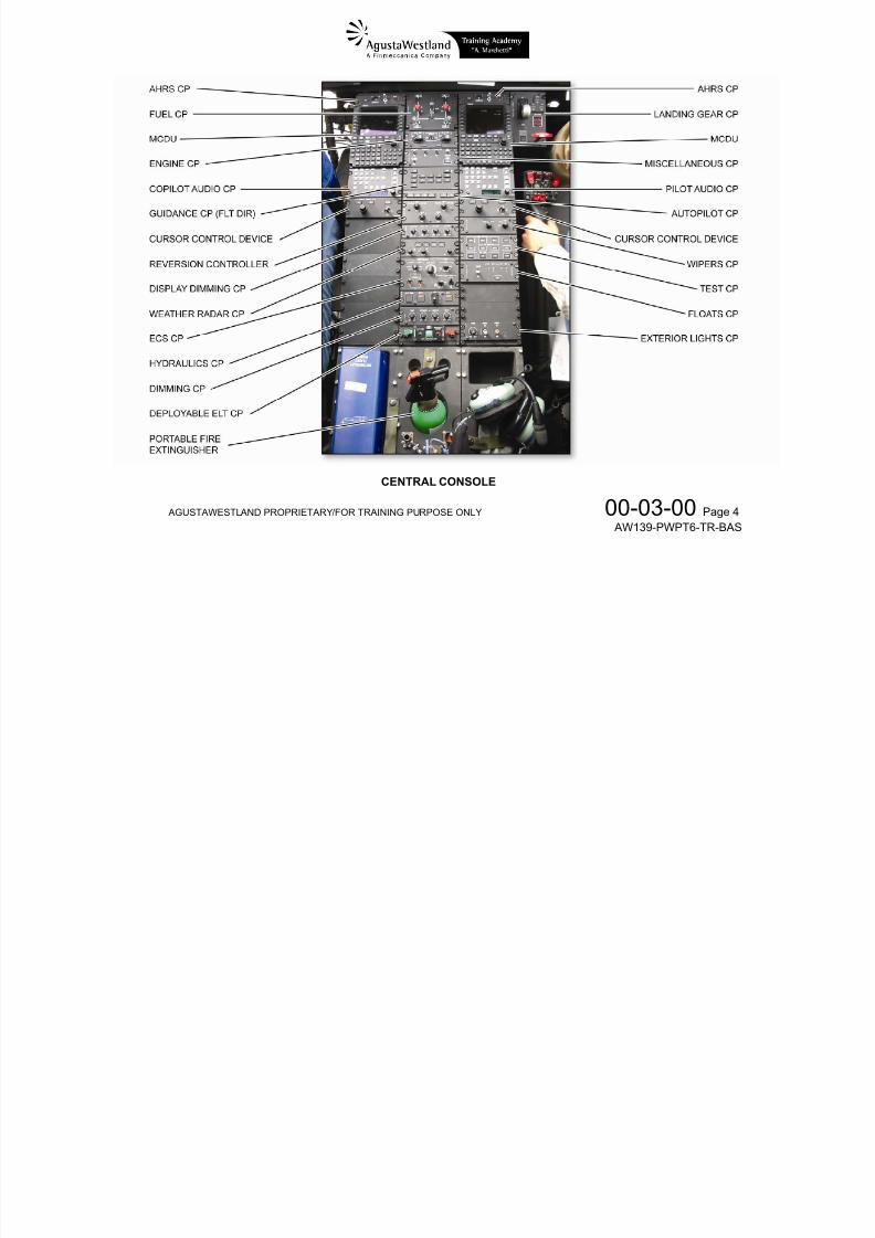
CENTRAL CONSOLE
7/22/2019 Aw139 Pwpt6 Tr Bas Lowres
http://slidepdf.com/reader/full/aw139-pwpt6-tr-bas-lowres 51/1016
AGUSTAWESTLAND PROPRIETARY/FOR TRAINING PURPOSE ONLY 00-03-00 Page 5 AW139-PWPT6-TR-BAS
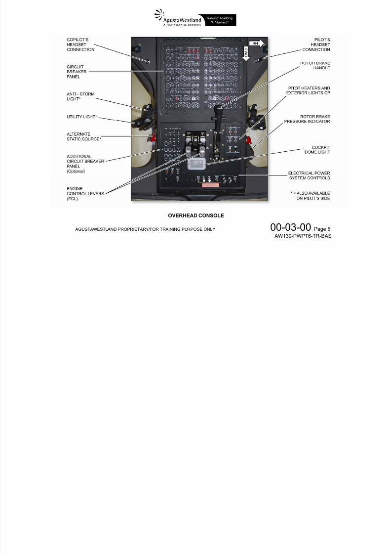
OVERHEAD CONSOLE
7/22/2019 Aw139 Pwpt6 Tr Bas Lowres
http://slidepdf.com/reader/full/aw139-pwpt6-tr-bas-lowres 52/1016
AG
USTAWESTLAN
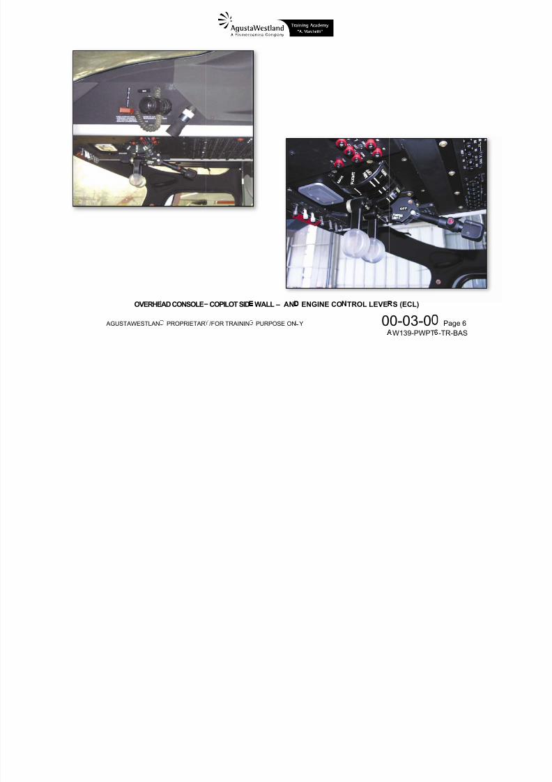
OVERHE
PROPRIETAR
AD CONSOLE
/FOR TRAININ
COPILOT SID
PURPOSE ON
WALL – AN
Y
ENGINE CO
0
TROL LEVE
0-03-0W139-PWPT
S (ECL)
Page 6 -TR-BAS
7/22/2019 Aw139 Pwpt6 Tr Bas Lowres
http://slidepdf.com/reader/full/aw139-pwpt6-tr-bas-lowres 53/1016
AGUSTAWESTLAND PROPRIETARY/FOR TRAINING PURPOSE ONLY 00-03-00 Page 7 AW139-PWPT6-TR-BAS
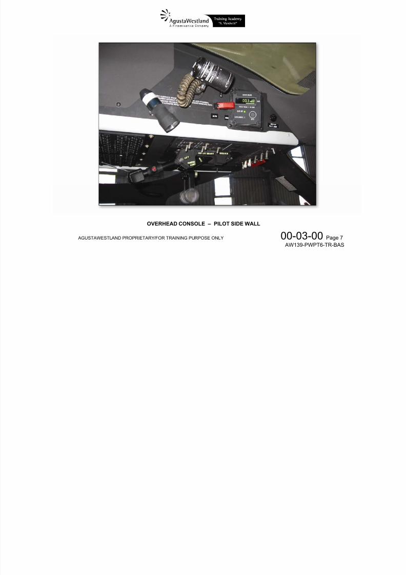
OVERHEAD CONSOLE – PILOT SIDE WALL
7/22/2019 Aw139 Pwpt6 Tr Bas Lowres
http://slidepdf.com/reader/full/aw139-pwpt6-tr-bas-lowres 54/1016
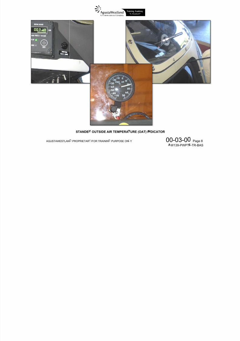
AG
USTAWESTLAN
PROPRIETAR
STANDB
/FOR TRAININ
OUTSIDE AI
PURPOSE ON
R TEMPERA
Y
URE (OAT) I
0
DICATOR
0-03-0W139-PWPT Page 8 -TR-BAS
7/22/2019 Aw139 Pwpt6 Tr Bas Lowres
http://slidepdf.com/reader/full/aw139-pwpt6-tr-bas-lowres 55/1016
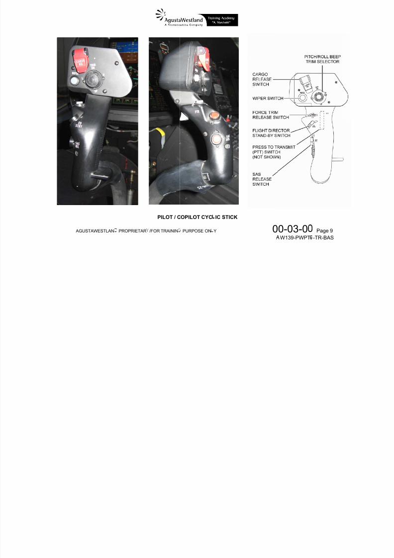
AG
USTAWESTLAN
PROPRIETAR
/FOR TRAININ
PILOT / C
PURPOSE ON
OPILOT CYC
Y
IC STICK
0 0-03-0W139-PWPT Page 9 -TR-BAS
7/22/2019 Aw139 Pwpt6 Tr Bas Lowres
http://slidepdf.com/reader/full/aw139-pwpt6-tr-bas-lowres 56/1016
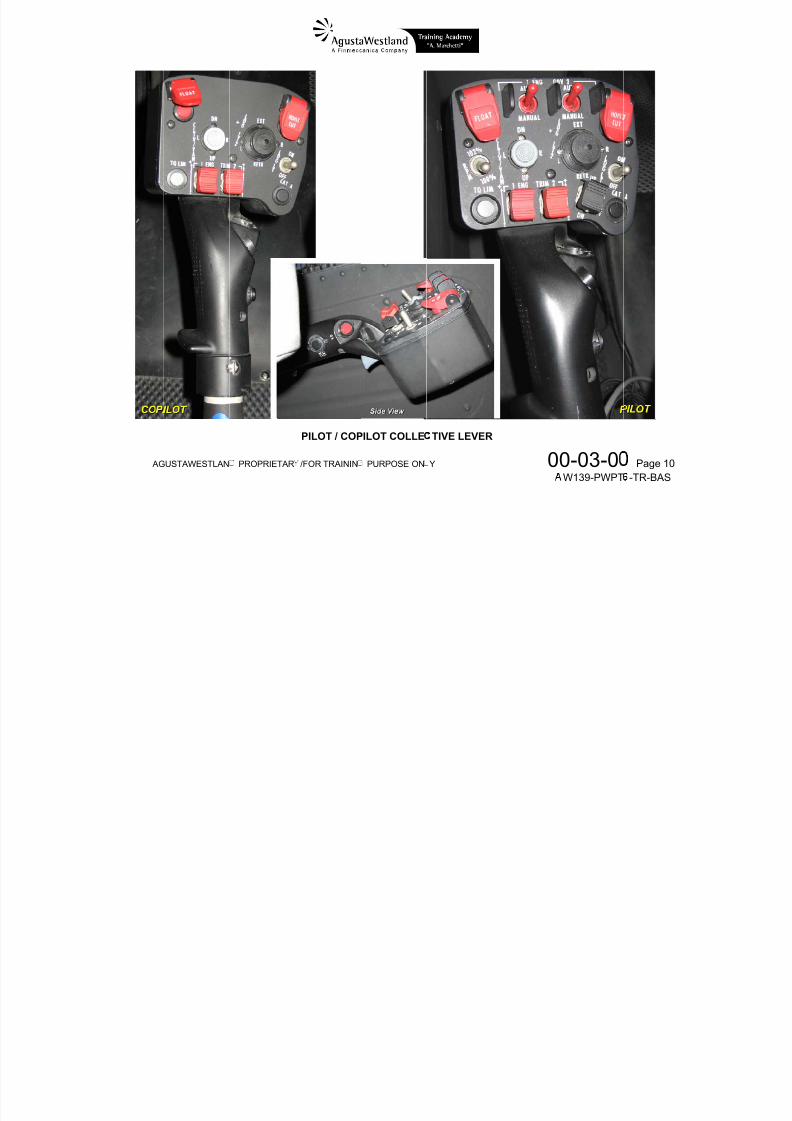
AG
USTAWESTLAN
PROPRIETAR
/FOR TRAININ
PILOT / COP
PURPOSE ON
ILOT COLLE
Y
TIVE LEVER
0 0-03-0W139-PWPT Page 10 -TR-BAS
7/22/2019 Aw139 Pwpt6 Tr Bas Lowres
http://slidepdf.com/reader/full/aw139-pwpt6-tr-bas-lowres 57/1016
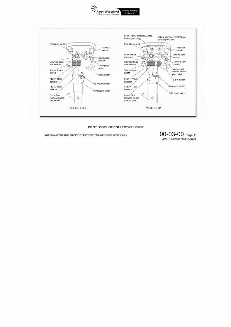
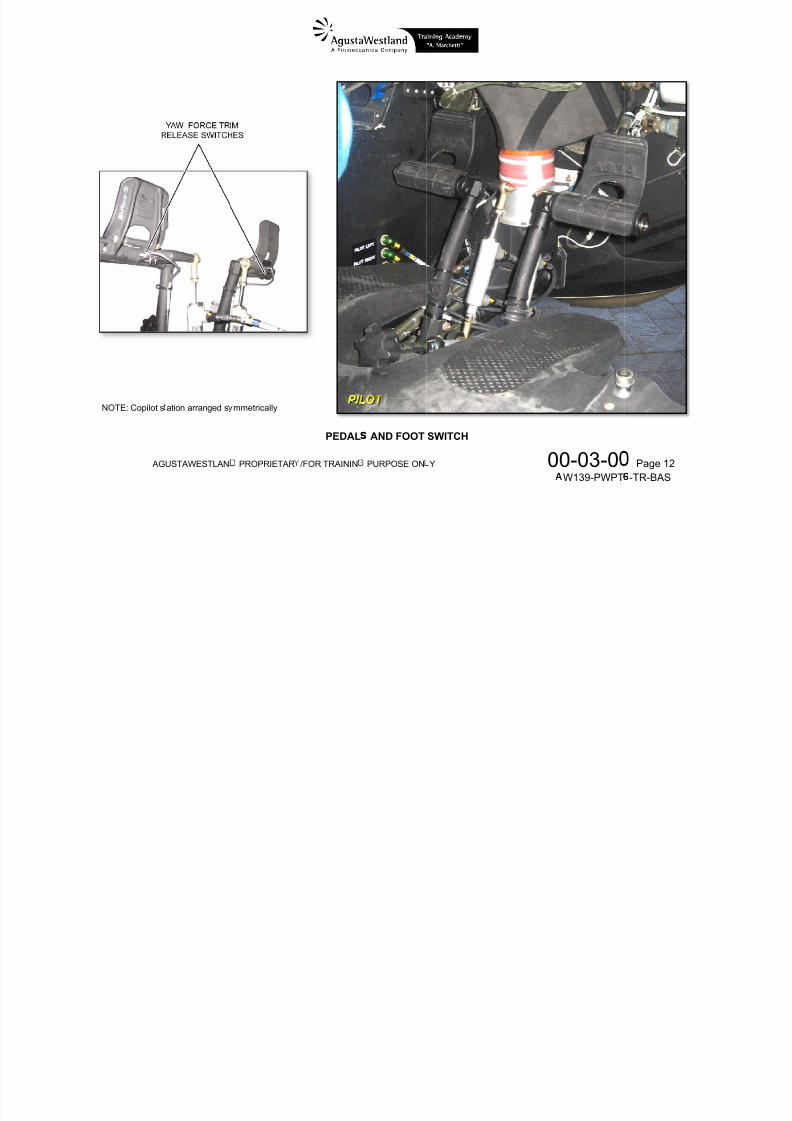
AGUSTAWESTLAND PROPRIETARY/FOR TRAINING PURPOSE ONLY 00-03-00 Page 11 AW139-PWPT6-TR-BAS
PILOT / COPILOT COLLECTIVE LEVER
7/22/2019 Aw139 Pwpt6 Tr Bas Lowres
http://slidepdf.com/reader/full/aw139-pwpt6-tr-bas-lowres 58/1016
AG
NOTE: Copilot s
USTAWESTLAN
ation arranged s
PROPRIETAR
mmetrically
/FOR TRAININ
PEDAL
PURPOSE ON
AND FOOT
Y
SWITCH
0 0-03-0W139-PWPT Page 12 -TR-BAS

7/22/2019 Aw139 Pwpt6 Tr Bas Lowres
http://slidepdf.com/reader/full/aw139-pwpt6-tr-bas-lowres 59/1016
AGUSTAWESTLAND PROPRIETARY/FOR TRAINING PURPOSE ONLY 00-11-00 Page 1 AW139-PWPT6-TR-BAS
CHAPTER
00AIR VEHICLE GENERAL
SECTION 11 – ACRONYMS LIST
7/22/2019 Aw139 Pwpt6 Tr Bas Lowres
http://slidepdf.com/reader/full/aw139-pwpt6-tr-bas-lowres 60/1016
AGUSTAWESTLAND PROPRIETARY/FOR TRAINING PURPOSE ONLY 00-11-00 Page 2 AW139-PWPT6-TR-BAS
A ASCB-D Avionics Standard Communication Bus ver.D
7/22/2019 Aw139 Pwpt6 Tr Bas Lowres
http://slidepdf.com/reader/full/aw139-pwpt6-tr-bas-lowres 61/1016
AGUSTAWESTLAND PROPRIETARY/FOR TRAINING PURPOSE ONLY 00-11-00 Page 3 AW139-PWPT6-TR-BAS
AC Alternating Current ACCB Air Conditioning Control Box ACP Audio Control Panel ADC Air Data Computer ADI Attitude Director Indicator ADF Automatic Direction Finder ADM Air Data Module ADS Air Data System
AEO All Engine Operative A/F Airframe AFCS Automatic Flight Control System AGB Accessory Gear Box AGL Above Ground Level Ah Ampere hour AHRS Attitude And Heading Reference System AHRU Attitude Heading Reference Unit AIOP Actuator Input/Output Processor (Module) ALS Ambient Light Sensor ALT Barometric Altitude ALTA Altitude Acquire ALT SEL Altitude Select AMLCD Active Matrix Liquid Crystal Display AMM Air Management Module
AMSL Above Mean Sea Level AOA Angle of attack AP Autopilot APP Approach APM Aircraft Personality Module ARINC Aeronautical Radio Inc.
ASEL Altitude Preselect ATC Air Traffic Control ATT Attitude retention mode AWG Aural Warning Generator
B
BC Back Course
BDGW Basic Design Gross WeightBFO Beat Frequency OscillatorBIT Built In TestBL Buttock LineBOD Bottom Of DescentBOV Bleed ValveBOW Basic Operating WeightBRG Bearing
C
°C Celsius degreeCAS Crew Alerting SystemCAS Calibrated Air Speed
CB Circuit BreakerCCD Cursor Control DeviceCCP Cockpit Control PanelCCU Cockpit Control UnitCCW Counter Clock-WiseCG Center of Gravity
CIO Control Input/Output (MAU Module) DR Dead Reckoning
7/22/2019 Aw139 Pwpt6 Tr Bas Lowres
http://slidepdf.com/reader/full/aw139-pwpt6-tr-bas-lowres 62/1016
AGUSTAWESTLAND PROPRIETARY/FOR TRAINING PURPOSE ONLY 00-11-00 Page 4 AW139-PWPT6-TR-BAS
p p ( )CMC Central Maintenance ComputerCMC-RT Central Maintenance Computer Remote TerminalCMS Central Maintenance SystemCOMM CommunicationCPI Crash Position IndicatorCPLT CopilotCPL Coupled/DecoupledCSIO Custom Input/Output (MAU Module)CVR Cockpit Voice Recorder
CW Clock-WiseCWS Central Warning System
D
DAU Digital Acquisition UnitDBM Data Base ModuleDC Direct CurrentDCL DecelerationDCM Detachable Configuration ModuleDCU Data Collection UnitDF Directional FinderDG Directional GyroDGPS Differential Global Positioning System
DGR DegradedDH Decision HeightDICP Display Instrument Control PanelDME Distance Measuring EquipmentDMG Digital Map GeneratorDN Down
gDU Display UnitDWS Debris Warning System
E
EAPS Engine Air Particle SeparatorEASA European Aviation Safety AgencyECL Engine Control Lever
ECP Engine Control PanelECS Environmental Control SystemECU Engine Control UnitEDU Electronic Display UnitEEC Electronic Engine ControlEFIS Electronic Flight Instrument SystemEGPWS Enhanced Ground Proximity Warning SystemEICAS Engine Instrument and Crew Alerting SystemELT Emergency Locator SystemEMS Emergency Medical ServiceENAC Ente Nazionale Aviazione CivileEPU Estimated Position UncertaintyET Elapsed TimeEX ExtensionEXT External
F
FAA Federal Aviation AdministrationFCC Flight Control Circuit
F/C Flight Control
7/22/2019 Aw139 Pwpt6 Tr Bas Lowres
http://slidepdf.com/reader/full/aw139-pwpt6-tr-bas-lowres 63/1016
AGUSTAWESTLAND PROPRIETARY/FOR TRAINING PURPOSE ONLY 00-11-00 Page 5 AW139-PWPT6-TR-BAS
FCU Fuel Computer UnitFD Flight DirectorFDR Flight Data RecorderFDR Flight Data RecorderFH Flying HoursFLIR Forward Looking Infra RedFMCW Frequency Modulated Continuous WaveFMM Fuel Management ModuleFMS Flight Management System
FOD Foreign Object DamageFOG Fiber Optic GyroFOM Figure of MeritFTR Force Trim ReleaseFWD Forward
G
GA Go-AroundGBS Ground Based SoftwareGC Guidance ControllerGCU Generation Control UnitGI Ground IdleGOV Governor (Engine)
GPS Global Positioning SystemGPWS Ground Proximity Warning SystemGS Glide SlopeGSE Ground Support EquipmentGW Gross Weight
H
HCB Heating Control BoxHDG HeadingHF High FrequencyHOV HoverHP High PressureHP Horse PowerHSI Horizontal Situation Indicator
I
IAS Indicated Air SpeedICS Intercommunication SystemIDS Integrated Display SystemIFR Instrument Flight RulesIGB Intermediate GearboxIGE In Ground EffectILS Instrument Landing SystemIR Infra RedISA International Standard Atmosphere
J
JAA Joint Aviation AuthorityJAR Joint Airworthiness Regulations
L MKR BCN Marker Beacon
7/22/2019 Aw139 Pwpt6 Tr Bas Lowres
http://slidepdf.com/reader/full/aw139-pwpt6-tr-bas-lowres 64/1016
AGUSTAWESTLAND PROPRIETARY/FOR TRAINING PURPOSE ONLY 00-11-00 Page 6 AW139-PWPT6-TR-BAS
LAN Local Area NetworkLAT LateralLCD Liquid Crystal DisplayLDG LandingLED Light Emitting DiodeLGCL Landing Gear Control LeverLGCP Landing Gear Control PanelLGCV Landing Gear Control Valve
LH Left HandLLS Lightning Sensor SystemLONG LongitudinalLOS Line-of-SightLRM Line Replaceable ModuleLRU Line Replaceable UnitLSS Lightning Sensor SystemLT LightLVDT Linear Variable Differential Transducer
M
MAU Modular Avionics UnitMB Marker Beacon
MCDU Multifunction Control Display UnitMCL Master Caution LightMCP Maximum Continuous PowerMDA Minimum Descent AltitudeMFD Multi-Function DisplayMGB Main Gear Box
MLG Main Landing GearMLS Microwave Landing SystemMPFDR Multipurpose Flight Data RecorderMPOG Minimum Pitch On GroundMR Main RotorMRA Main Rotor ActuatorMRC Modular Radio CabinetMTBF Mean Time Between FailuresMTTR Maintenance Time to Replace
MWL Master Warning Light
N
NAV Lateral NavigationNf or NF Engine free turbine speedNg Engine gas generator turbineNIC Network Interface ControllerNIM Network Interface ModuleNLG Nose Landing GearNM Nautical MileNr Rotor rpmNVG Night Vision GoggleNVM Non Volatile Memory
O
OAT Outer Air TemperatureOEI One Engine Inoperative
OGE Out of Ground Effect RHT Radar Altitude HoldRIC R I C ll
7/22/2019 Aw139 Pwpt6 Tr Bas Lowres
http://slidepdf.com/reader/full/aw139-pwpt6-tr-bas-lowres 65/1016
AGUSTAWESTLAND PROPRIETARY/FOR TRAINING PURPOSE ONLY 00-11-00 Page 7 AW139-PWPT6-TR-BAS
P
PAX PassengersPCM Power Control ModulePDP Power Distribution PanelPFD Primary Flight DisplayPI Power Index
PLA Power Lever Angle (throttle)PWR Power
Q
R
R/A Retract ActuatorRADALT Radio AltitudeRB Rotor BrakeRBA Rotor Brake AssemblyRBAA Rotor Brake Actuation AssemblyRBCL Rotor Brake Control Lever
RBCM Rotor Brake Control ModuleRBPI Rotor Brake Pressure IndicatorRBRB Rotor Brake Relays BoxRCP Reversion Control PanelRFM Rotorcraft Flight ManualRH Right Hand
RIC Remote Instrument ControllerRICP Remote Instrument Control PanelRNAV Area NavigationRNP Required Navigation PerformanceROC Rate of ClimbRPM Revolution Per MinuteRSB Radio System BusRTD Resistance Temperature Device
S
SA Shortening ActuatorSAR Search and RescueSAS Stability Augmentation SystemSHP Shaft Horse PowerS/N Serial NumberSOV Shut Off ValveSTA Station (line)STAR Standard Terminal Arrival RouteSTBY Stand-By
T
TAWS Terrain Awareness and Warning SystemTACAN Tactical Air NavigationTAS True Air SpeedTBD To Be DefinedTBO Time Between Overhaul
TCAS Traffic Alert and Collision Avoidance SystemTCPS T t C t d P S it h
VIP Very Important PersonVMS V hi l M it i g S t
7/22/2019 Aw139 Pwpt6 Tr Bas Lowres
http://slidepdf.com/reader/full/aw139-pwpt6-tr-bas-lowres 66/1016
AGUSTAWESTLAND PROPRIETARY/FOR TRAINING PURPOSE ONLY 00-11-00 Page 8 AW139-PWPT6-TR-BAS
TCPS Temperature Compensated Pressure SwitchTCV Temperature Control ValveTGB Tail Gear BoxTO Take OffTOC Top Of ClimbTOD Top Of DescentTOP Take Off PowerTQ Engine TorqueTR Tail Rotor
TRA Tail Rotor ActuatorTRSOV Tail Rotor Shut-Off Valve
U
UHF Ultra High FrequencyUP UpUTIL SOV Utility Shut-Off Valve
V
VLO Maximum landing gear operating speedVLE Maximum landing gear extended speed
VNE Never Exceed speedVDR VHF Data RadioVFR Visual Flight RulesVGP Vertical Glide PathVHF Very High FrequencyVIDL VOR/ILS Data Link
VMS Vehicle Monitoring SystemVOR VHF Omnidirectional RangeVREF Reference SpeedVROC Vertical Rate Of ClimbVS Vertical SpeedVSI Vertical Speed Indicator
W
WGT WeightWL Water LineWOW Weight-On-WheelsWXR Weather Radar
X
XFEED CrossfeedXPDR Transponder
Y
Z

7/22/2019 Aw139 Pwpt6 Tr Bas Lowres
http://slidepdf.com/reader/full/aw139-pwpt6-tr-bas-lowres 67/1016
AGUSTAWESTLAND PROPRIETARY/FOR TRAINING PURPOSE ONLY 00-40-00 Page 1 AW139-PWPT6-TR-BAS
CHAPTER00AIR VEHICLE GENERAL
SECTION 40 – TECHNICAL PUBLICATION
7/22/2019 Aw139 Pwpt6 Tr Bas Lowres
http://slidepdf.com/reader/full/aw139-pwpt6-tr-bas-lowres 68/1016
AGUSTAWESTLAND PROPRIETARY/FOR TRAINING PURPOSE ONLY 00-40-00 Page 2 AW139-PWPT6-TR-BAS
GENERAL RFM TABLE OF CONTENTS
PART I E A S A APPROVED
7/22/2019 Aw139 Pwpt6 Tr Bas Lowres
http://slidepdf.com/reader/full/aw139-pwpt6-tr-bas-lowres 69/1016
AGUSTAWESTLAND PROPRIETARY/FOR TRAINING PURPOSE ONLY 00-40-00 Page 3 AW139-PWPT6-TR-BAS
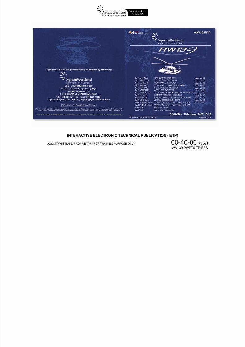
The flight and maintenance operations must be carried outaccording to the officially issued documents which arecomposed of
• Rotorcraft Flight Manual (RFM)• Interactive Electronic Technical Publication (IETP)
- Maintenance Publication
- Component Repair and Overhaul Manual- Structural Repair Manual- Illustrated Parts Catalogue- Fault Isolation Manual- Wiring Diagram Manual-
Illustrated Tools and Equipment Manual- Master Minimum Equipment List
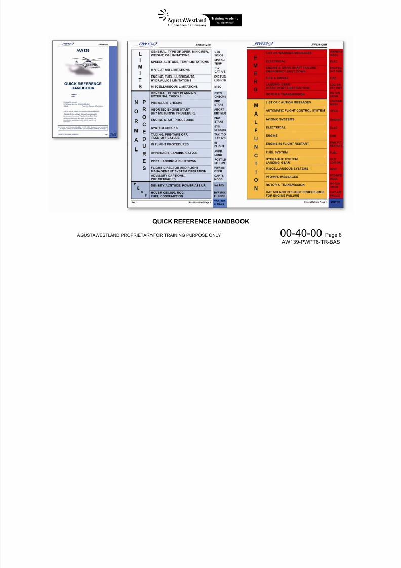
In addition a Quick Reference Handbook (QRH) is alsoavailable as a checklist that is mandatory for single-pilotoperations.
ROTORCRAFT FLIGHT MANUAL (RFM)
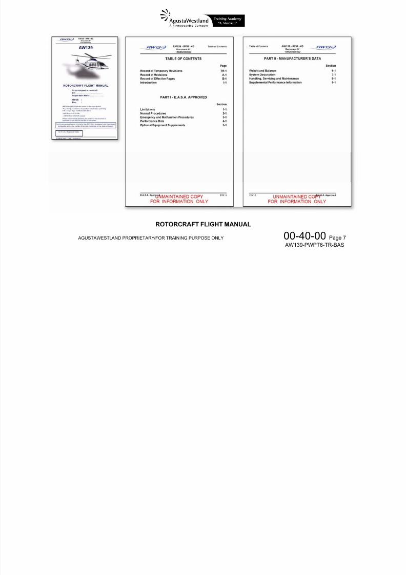
It provides all the information required to operate thehelicopter in normal and emergency conditions. It is dividedinto
PART I – E.A.S.A. APPROVED• 1 - Limitations• 2 - Normal Procedures• 3 - Emergency and Malfunctions Procedures• 4 - Performances Data• 5 - Optional Equipment Supplement
PART II – MANUFACTURER’S DATA• 6 - Weight and Balance• 7 - Systems Description• 8 - Handling, Servicing and Maintenance•
9 - Supplemental Performance Information
The Limitations section contains limitations required byregulation or to safely operate rotorcraft, powerplant, systems,and equipment. It includes operating limitations, instrumentmarkings, colour coding, and basic placards.
The Normal Procedures section contains the checklist for thenormal procedures ordered by phase of flight. Normalprocedures are the result of extensive flight tests andexperience with the AW139 aircraft. They are intended toensure that the level of safety required by the design andcertification process is achieved.
The Emergency and Malfunctions Procedures section• Section 2 – Normal procedures
S i 3 E d lf i P d
7/22/2019 Aw139 Pwpt6 Tr Bas Lowres
http://slidepdf.com/reader/full/aw139-pwpt6-tr-bas-lowres 70/1016
AGUSTAWESTLAND PROPRIETARY/FOR TRAINING PURPOSE ONLY 00-40-00 Page 4 AW139-PWPT6-TR-BAS
g ycontains the procedures that must be performed in the eventof an emergency or malfunction. These procedures are basedon experience acquired in the operation of helicopters, ingeneral, and on flight tests conducted on AW139 helicopter.The Emergency and Malfunction procedures are presented inthe form of logic trees (flow charts). These flow charts havebeen formulated based on analysis and test of the cockpitindications that would be available to the flight crew following
the failures/malfunctions that are included in this section. Thesection includes three sets of procedures:• Emergency procedures for CAS messages• Malfunction procedures for CAS messages• Emergency and malfunction procedures for PDF
indications
Emergency procedures are related to warning (red)messages/indications.Malfunction procedures are related to caution (amber)messages/indications.
The Performance Data section includes charts with standardperformance data based on flight test results and engineering
analysis.
The Optional Equipment Supplement section contains all theinformation necessary to operate optional equipment. Eachsupplement is arranged in 4 sections:
• Section 1 – Limitations
• Section 3 – Emergency and malfunction Procedures• Section 4 – Performance Data
The weight and balance data contain the charts that permit todetermine the aircraft weight and the position of the center ofgravity.
INTERACTIVE ELECTRONIC TECHNICAL PUBLICATION(IETP)
The IETP is distributed on CD-ROM and includes all thetechnical publications used to properly perform allmaintenance tasks to permit the Release To Service of the
AW139 helicopter, including the Master Minimum EquipmentList (MMEL).
MAINTENANCE PUBLICATION
It provides all the information required to perform all theprocedures used to preserve the airworthiness and flightcharacteristic of the helicopter. It contains the followinginformation
•
inspection requirements• maintenance procedures• removal and installation procedures• test and inspection
COMPONENT REPAIR AND OVERHAUL MANUAL
It provides all the information required to the disassembly
MASTER MINIMUM EQUIPMENT LIST
It provides the list of all the airborne equipment which is
7/22/2019 Aw139 Pwpt6 Tr Bas Lowres
http://slidepdf.com/reader/full/aw139-pwpt6-tr-bas-lowres 71/1016
AGUSTAWESTLAND PROPRIETARY/FOR TRAINING PURPOSE ONLY 00-40-00 Page 5
AW139-PWPT6-TR-BAS
It provides all the information required to the disassembly,
inspection, repair and reassembly of the major helicoptercomponents when applicable.
STRUCTURAL REPAIR MANUAL
It provides all the information required for the identification ofstructure damages and the repair associated.
ILLUSTRATED PARTS CATALOGUE
It provides all the illustration and identification data about thereplaceable parts of the air vehicle for which the maintenanceprocedures has been provided.
FAULT ISOLATION MANUAL
It provides all the information and procedures required by theuser to isolate faults not identified by built-in test equipment.
WIRING DIAGRAM MANUAL
It provides all the electrical/electronic wiring diagrams requiredfor maintenance tasks.
ILLUSTRATED TOOLS AND EQUIPMENT MANUAL
It provides all the characteristics and the illustrations of all thespecial tools and equipment, including test equipmentrecommended for the maintenance of the air vehicle.
It provides the list of all the airborne equipment which is
mandatory to achieve a safe flight condition.
7/22/2019 Aw139 Pwpt6 Tr Bas Lowres
http://slidepdf.com/reader/full/aw139-pwpt6-tr-bas-lowres 72/1016
AGUSTAWESTLAND PROPRIETARY/FOR TRAINING PURPOSE ONLY 00-40-00 Page 6
AW139-PWPT6-TR-BAS
INTERACTIVE ELECTRONIC TECHNICAL PUBLICATION (IETP)
7/22/2019 Aw139 Pwpt6 Tr Bas Lowres
http://slidepdf.com/reader/full/aw139-pwpt6-tr-bas-lowres 73/1016
AGUSTAWESTLAND PROPRIETARY/FOR TRAINING PURPOSE ONLY 00-40-00 Page 7
AW139-PWPT6-TR-BAS
ROTORCRAFT FLIGHT MANUAL

7/22/2019 Aw139 Pwpt6 Tr Bas Lowres
http://slidepdf.com/reader/full/aw139-pwpt6-tr-bas-lowres 74/1016
AGUSTAWESTLAND PROPRIETARY/FOR TRAINING PURPOSE ONLY 00-40-00 Page 8
AW139-PWPT6-TR-BAS
QUICK REFERENCE HANDBOOK

7/22/2019 Aw139 Pwpt6 Tr Bas Lowres
http://slidepdf.com/reader/full/aw139-pwpt6-tr-bas-lowres 75/1016
AGUSTAWESTLAND PROPRIETARY/FOR TRAINING PURPOSE ONLY 21-00-00 Page 1
AW139-PWPT6-TR-BAS
CHAPTER21
ENVIRONMENTAL CONTROL
SECTION 00 – GENERAL

7/22/2019 Aw139 Pwpt6 Tr Bas Lowres
http://slidepdf.com/reader/full/aw139-pwpt6-tr-bas-lowres 76/1016
AGUSTAWESTLAND PROPRIETARY/FOR TRAINING PURPOSE ONLY 21-00-00 Page 2
AW139-PWPT6-TR-BAS
ENVIRONMENTAL CONTROL – GENERAL
The en ironmental control s stem consists of the follo ing

7/22/2019 Aw139 Pwpt6 Tr Bas Lowres
http://slidepdf.com/reader/full/aw139-pwpt6-tr-bas-lowres 77/1016
AGUSTAWESTLAND PROPRIETARY/FOR TRAINING PURPOSE ONLY 21-00-00 Page 3
AW139-PWPT6-TR-BAS
The environmental control system consists of the followingsub-systems:
• ventilation• heating• air conditioning
VENTILATION SYSTEM – GENERAL
The purpose of the ventilation system is to supply fresh air tothe cockpit and cabin.
The ventilation system is composed of three independent sub-systems as follows:
• Pilot ventilation sub-system• Copilot ventilation sub-system• Cabin ventilation sub-system
Pilot and copilot ventilation systems make up the cockpitventilation system controlled by a single CREW selector onthe Environmental Control System (ECS) control panel.
The cabin ventilation system is controlled by the PAX selectoron the ECS control panel.
COCKPIT VENTILATION - GENERAL
Pilot and copilot ventilation systems are independent and
7/22/2019 Aw139 Pwpt6 Tr Bas Lowres
http://slidepdf.com/reader/full/aw139-pwpt6-tr-bas-lowres 78/1016
AGUSTAWESTLAND PROPRIETARY/FOR TRAINING PURPOSE ONLY 21-00-00 Page 4
AW139-PWPT6-TR-BAS
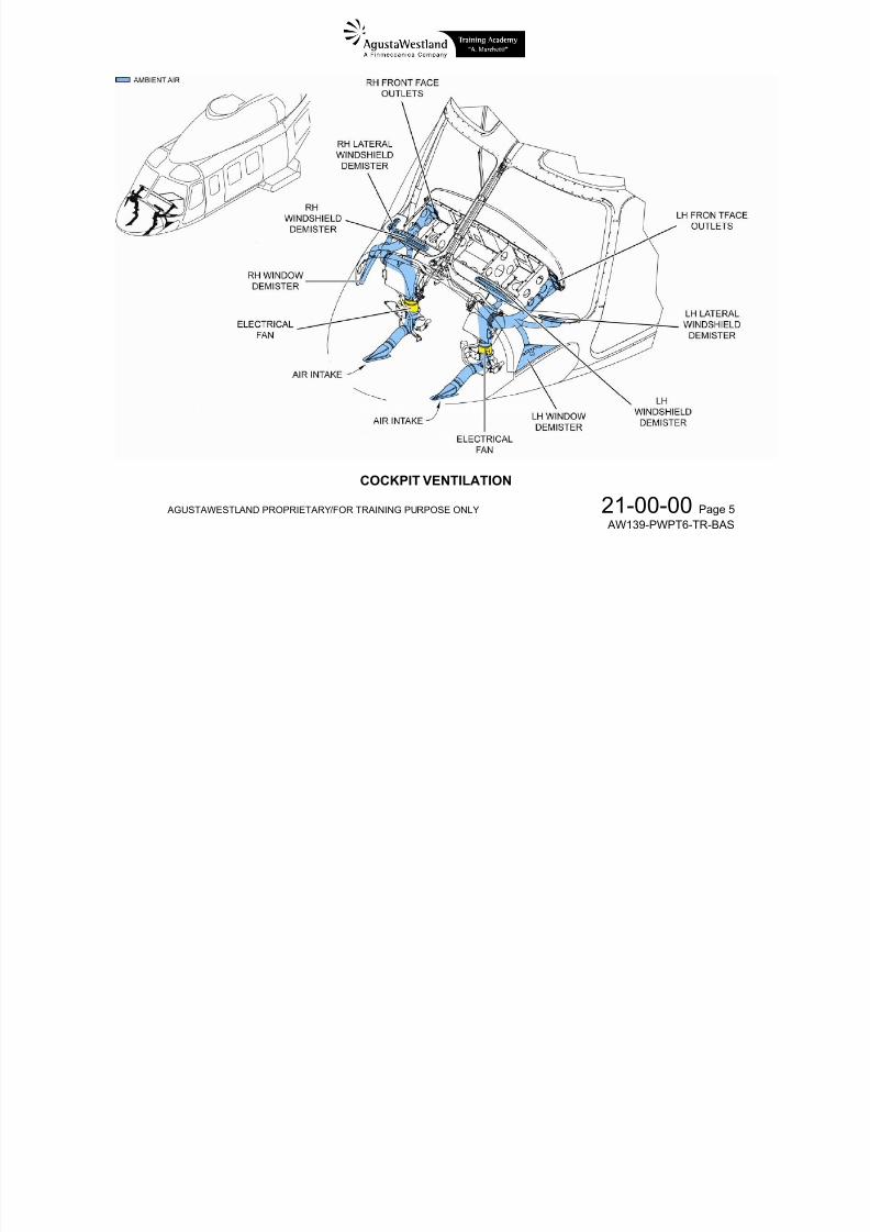
Pilot and copilot ventilation systems are independent andarranged symmetrically but controlled by a single rotary knobonly (VENT CREW). Each of them is composed of:
• a ram air intake located under the lower part of the nosecompartment
• a flapper valve, electrically controlled to be either fullyopen (ventilation on) or fully closed (ventilation off)
• an electrical fan for forced air operation• five outlets:- two adjustable face outlets on the instruments panel- two free outlets for the windshield (main and side)- one free outlet for the lower window.

7/22/2019 Aw139 Pwpt6 Tr Bas Lowres
http://slidepdf.com/reader/full/aw139-pwpt6-tr-bas-lowres 79/1016
AGUSTAWESTLAND PROPRIETARY/FOR TRAINING PURPOSE ONLY 21-00-00 Page 5
AW139-PWPT6-TR-BAS
COCKPIT VENTILATION
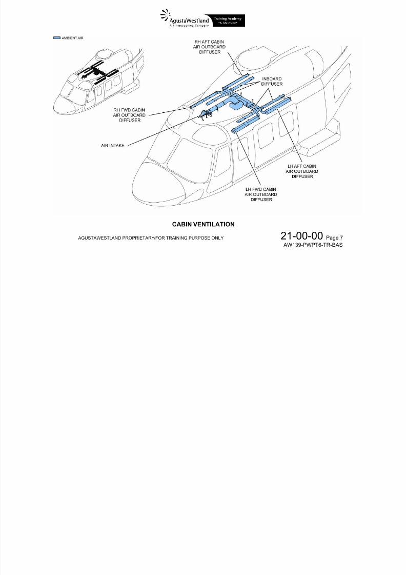
CABIN VENTILATION - GENERAL
The cabin ventilation system is a single independent system
7/22/2019 Aw139 Pwpt6 Tr Bas Lowres
http://slidepdf.com/reader/full/aw139-pwpt6-tr-bas-lowres 80/1016
AGUSTAWESTLAND PROPRIETARY/FOR TRAINING PURPOSE ONLY 21-00-00 Page 6
AW139-PWPT6-TR-BAS
The cabin ventilation system is a single independent systemwhich provides fresh air to passengers and is composed of:
• a ram air intake located on the upper deck fairing• a flapper valve electrically controlled to be either fully
open (ventilation on) or fully closed (ventilation off)• two electrical fans for forced air operation•
twelve adjustable outlets located in the PSUs (PassengerService Units)

7/22/2019 Aw139 Pwpt6 Tr Bas Lowres
http://slidepdf.com/reader/full/aw139-pwpt6-tr-bas-lowres 81/1016
AGUSTAWESTLAND PROPRIETARY/FOR TRAINING PURPOSE ONLY
21-00-00 Page 7
AW139-PWPT6-TR-BAS
CABIN VENTILATION
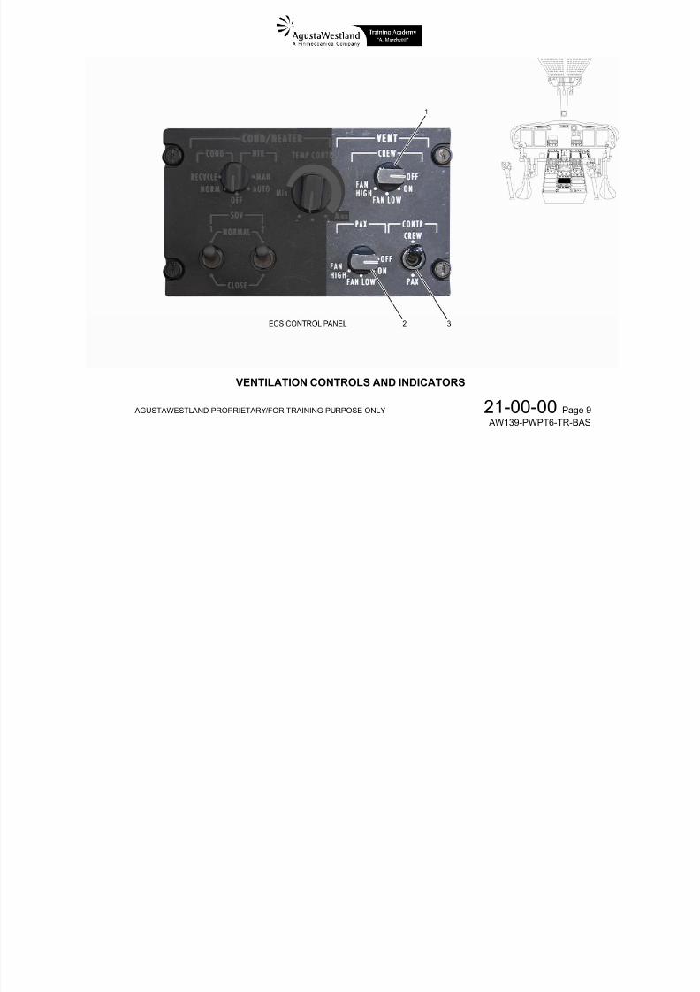
VENTILATION SYSTEM – CONTROLS AND INDICATORS
7/22/2019 Aw139 Pwpt6 Tr Bas Lowres
http://slidepdf.com/reader/full/aw139-pwpt6-tr-bas-lowres 82/1016
AGUSTAWESTLAND PROPRIETARY/FOR TRAINING PURPOSE ONLY
21-00-00 Page 8
AW139-PWPT6-TR-BAS
1. VENT CREW rotary knobOFF ..…................…….. pilot and copilot flapper valves are closed (no airflow)
ON .....…………………... pilot and copilot flapper valves are open (ram airflow)
FAN LOW .….................
FAN HIGH …………...…
pilot and copilot flapper valves are open and electrical fan operates at low speed (forced airflow)
pilot and copilot flapper valves are open and electrical fan operates at high speed (forced airflow)
2. VENT PAX rotary knobOFF ..…...…………..….. cabin flapper valves are closed (no airflow)
ON .....………………….. cabin flapper valves are open (ram airflow)
FAN LOW .….................
FAN HIGH …………...…
cabin flapper valves are open and electrical fan operates at low speed (forced airflow)
cabin flapper valves are open and electrical fan operates at high speed (forced airflow)
3. VENT CONTR switchCREW ...…................…. enables the VENT PAX rotary switch (2)
PAX ...…………………... enables the VENT rotary switch in the cabin (optional)
NOTE. If the cabin controller is not installed, selecting the VENT CONTR switch to PAX causes thecabin flapper valves to open (ram airflow) and disables the VENT PAX rotary switch.
7/22/2019 Aw139 Pwpt6 Tr Bas Lowres
http://slidepdf.com/reader/full/aw139-pwpt6-tr-bas-lowres 83/1016
AGUSTAWESTLAND PROPRIETARY/FOR TRAINING PURPOSE ONLY
21-00-00 Page 9
AW139-PWPT6-TR-BAS
VENTILATION CONTROLS AND INDICATORS
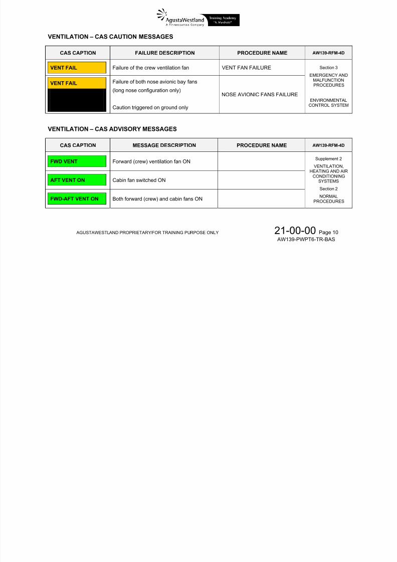
VENTILATION – CAS CAUTION MESSAGES
AW139-RFM-4D

7/22/2019 Aw139 Pwpt6 Tr Bas Lowres
http://slidepdf.com/reader/full/aw139-pwpt6-tr-bas-lowres 84/1016
AGUSTAWESTLAND PROPRIETARY/FOR TRAINING PURPOSE ONLY
21-00-00 Page 10
AW139-PWPT6-TR-BAS
CAS CAPTION FAILURE DESCRIPTION PROCEDURE NAMEAW139 RFM 4D
VENT FAIL Failure of the crew ventilation fan VENT FAN FAILURE
VENT FAIL
NOSE FAN 1 OFF
NOSE FAN 2 OFF
Failure of both nose avionic bay fans
(long nose configuration only)
Caution triggered on ground only
NOSE AVIONIC FANS FAILURE
Section 3
EMERGENCY ANDMALFUNCTIONPROCEDURES
ENVIRONMENTALCONTROL SYSTEM
VENTILATION – CAS ADVISORY MESSAGES
CAS CAPTION MESSAGE DESCRIPTION PROCEDURE NAME AW139-RFM-4D
FWD VENT Forward (crew) ventilation fan ON
AFT VENT ON Cabin fan switched ON
FWD-AFT VENT ON Both forward (crew) and cabin fans ON
Supplement 2
VENTILATION,HEATING AND AIR
CONDITIONINGSYSTEMS
Section 2NORMAL
PROCEDURES
VENTILATION – LIMITATIONS
Refer to AW139-RFM-4D Section 1.

7/22/2019 Aw139 Pwpt6 Tr Bas Lowres
http://slidepdf.com/reader/full/aw139-pwpt6-tr-bas-lowres 85/1016
AGUSTAWESTLAND PROPRIETARY/FOR TRAINING PURPOSE ONLY
21-00-00 Page 11
AW139-PWPT6-TR-BAS
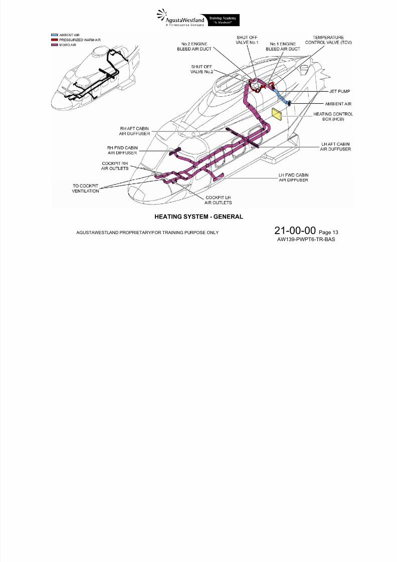
HEATING SYSTEM – GENERAL
The purpose of the heating system is to supply warm air to the
connected to the cockpit ventilation system and they are alsodedicated to the pilots.
7/22/2019 Aw139 Pwpt6 Tr Bas Lowres
http://slidepdf.com/reader/full/aw139-pwpt6-tr-bas-lowres 86/1016
AGUSTAWESTLAND PROPRIETARY/FOR TRAINING PURPOSE ONLY
21-00-00 Page 12
AW139-PWPT6-TR-BAS
cockpit and cabin to maintain a comfortable environment andto defrost windshields and lower windows.The heating system supplies cockpit and cabin with a mix ofhot pressurized air bled from the compressor discharge port(P3) of both engines and external air sucked in through an airinlet on the LH aft fuselage.Two solenoid controlled bleed air shut-off valves (SOV)control the relevant engine hot pressurized air to supply theheating system when selected on by the pilot and the engineoperates normally.The bleed air SOV are automatically closed if any of thefollowing occurs:
• a failure in the heating system is detected• engine is not running• fire extinguishing system is armed (see Ch.26-00-00)• loss of electrical control signal
The engine hot pressurized air is routed to the TemperatureControl Valve (TCV) which controls the quantity of hot air tobe mixed with outside fresh air sucked in by a jet pump. Themixing occurs in the jet pump.
The mixed air enters the cabin and the cockpit via the airdistribution ducts. The right and left diffusers are located onthe floor area. They provide the distribution of the heated airthrough the cabin (passenger area). The distribution ducts are
The airflow temperature is automatically controlled by theHeating Control Box (HCB) through the TEMP CONTR knobon the COND/HEATER control panel when the COND/HTRselector is set at AUTO.
In case of failure of the automatic temperature control, thepilot can manually control the position of the TCV by settingthe COND/HTR selector to MAN and using the TEMP CONTRknob as a trim switch in the positions.

7/22/2019 Aw139 Pwpt6 Tr Bas Lowres
http://slidepdf.com/reader/full/aw139-pwpt6-tr-bas-lowres 87/1016
AGUSTAWESTLAND PROPRIETARY/FOR TRAINING PURPOSE ONLY
21-00-00 Page 13
AW139-PWPT6-TR-BAS
HEATING SYSTEM - GENERAL
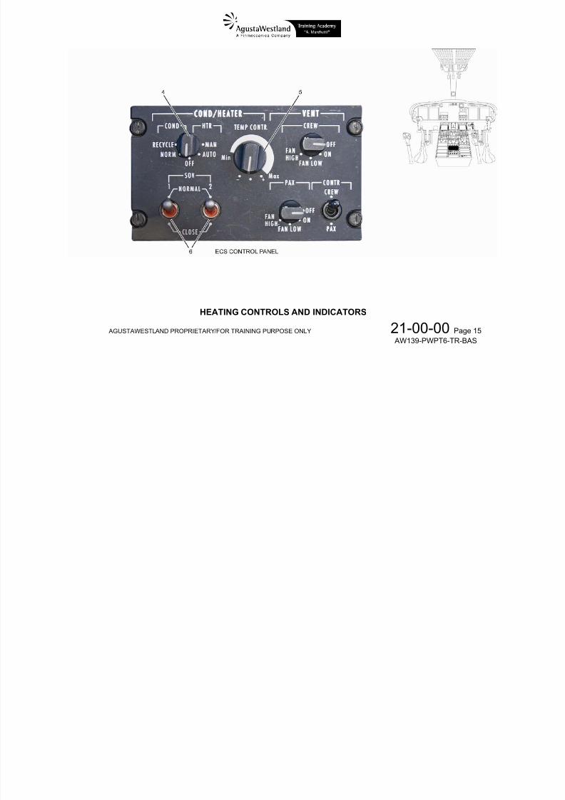
HEATING – CONTROLS AND INDICATORS
4 COND/HTR l
7/22/2019 Aw139 Pwpt6 Tr Bas Lowres
http://slidepdf.com/reader/full/aw139-pwpt6-tr-bas-lowres 88/1016
AGUSTAWESTLAND PROPRIETARY/FOR TRAINING PURPOSE ONLY
21-00-00 Page 14
AW139-PWPT6-TR-BAS
4. COND/HTR selectorOFF, NORM, RECYCLE …. the heating is off
AUTO ..…….……..…….... the heating system keeps the cockpit and the cabin air at the selected temperature automatically
MAN …..…..……..……..... the heating is operated in manual mode
5. TEMP CONTR knob (with COND/HTR selector in HTR area)
Min to Max range ….….. (potentiometer) selects the cockpit / cabin air temperature for automatic temperature control● .…………………...…… Neutral position for manual temperature control. No input is given to the TCV which stay still.+ .…………………..……. (momentary position) manually controls the TCV to open (increases temperature)
– .………………..……… (momentary position) manually controls the TCV to close (decreases temperature)
6. SOV 1 (2) switch
NORMAL ...…..……….... the no.1 (no.2) shut-off valve is automatically opened or closedCLOSE …......………….. the no.1 (no.2) shut-off valve is forced to close

7/22/2019 Aw139 Pwpt6 Tr Bas Lowres
http://slidepdf.com/reader/full/aw139-pwpt6-tr-bas-lowres 89/1016
AGUSTAWESTLAND PROPRIETARY/FOR TRAINING PURPOSE ONLY
21-00-00 Page 15
AW139-PWPT6-TR-BAS
HEATING CONTROLS AND INDICATORS
HEATING – CAS CAUTION MESSAGES
CAS CAPTION FAILURE DESCRIPTION PROCEDURE NAME AW139-RFM-4D

7/22/2019 Aw139 Pwpt6 Tr Bas Lowres
http://slidepdf.com/reader/full/aw139-pwpt6-tr-bas-lowres 90/1016
AGUSTAWESTLAND PROPRIETARY/FOR TRAINING PURPOSE ONLY 21-00-00 Page 16 AW139-PWPT6-TR-BAS
HEATER FAIL Heater system failure HEATER FAILURE
Supplement 2
VENTILATION, HEATING AND AIR
CONDITIONINGSYSTEMS
HEATING – CAS ADVISORY MESSAGES
CAS CAPTION MESSAGE DESCRIPTION PROCEDURE NAME AW139-RFM-4D
HEATER ON Heater switched ON
Supplement 2
VENTILATION, HEATING AND AIRCONDITIONING
SYSTEMS
HEATING – LIMITATIONS
Refer to AW139-RFM-4D Supplement 2.

7/22/2019 Aw139 Pwpt6 Tr Bas Lowres
http://slidepdf.com/reader/full/aw139-pwpt6-tr-bas-lowres 91/1016
AGUSTAWESTLAND PROPRIETARY/FOR TRAINING PURPOSE ONLY 21-00-00 Page 17 AW139-PWPT6-TR-BAS
AIR CONDITIONING - GENERAL
The purpose of the air conditioning system is to supply cool
air to the cockpit and the cabin to maintain a comfortable
The air conditioning system is supplied by circuit breakersgrouped as ECS and connected to NON-ESS 1 (cockpit) andNON-ESS 2 (cabin).
7/22/2019 Aw139 Pwpt6 Tr Bas Lowres
http://slidepdf.com/reader/full/aw139-pwpt6-tr-bas-lowres 92/1016
AGUSTAWESTLAND PROPRIETARY/FOR TRAINING PURPOSE ONLY 21-00-00 Page 18 AW139-PWPT6-TR-BAS
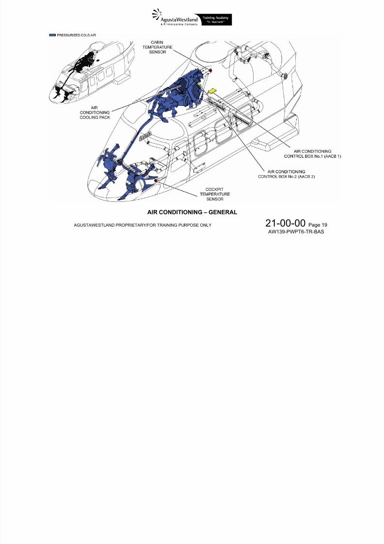
air to the cockpit and the cabin to maintain a comfortableenvironment.
The air conditioning system comprises two vapour cyclesystems, one for the cockpit and one for the cabin, which usetetrafluoroethane (Freon) as refrigerant. Freon is non-toxicand non-flammable gas. Each system includes a compressor,a condenser, a heat exchanger and an evaporator. Thecompressors are mechanically driven by the Main Gear Box(MGB) through electromagnetic clutches.The clutches open – thus mechanically disconnecting thecompressors from the MGB – when the air conditioning is off.
Two Air Conditioning Control Boxes (ACCBs) compare the airtemperature measured by the cockpit and cabin sensors with
the temperature set on the ECS control panel and operate therelated compressor on/off cycle as necessary.
Freon cools the ventilation air through the heat exchangerslocated in the cockpit and cabin ventilation ducts. In NORMmode the ventilation flapper valves are open and ram air iscooled. In RECYCLE mode the ventilation system flappervalves are closed and the recycle flapper valves are open:cockpit and cabin air is recirculated through the heatexchangers by the electrical fans and cooled.

7/22/2019 Aw139 Pwpt6 Tr Bas Lowres
http://slidepdf.com/reader/full/aw139-pwpt6-tr-bas-lowres 93/1016
AGUSTAWESTLAND PROPRIETARY/FOR TRAINING PURPOSE ONLY 21-00-00 Page 19 AW139-PWPT6-TR-BAS
AIR CONDITIONING – GENERAL
AIR CONDITIONING – CONTROLS AND INDICATORS
ECS control panel
7 COND/HTR l t

7/22/2019 Aw139 Pwpt6 Tr Bas Lowres
http://slidepdf.com/reader/full/aw139-pwpt6-tr-bas-lowres 94/1016
AGUSTAWESTLAND PROPRIETARY/FOR TRAINING PURPOSE ONLY 21-00-00 Page 20 AW139-PWPT6-TR-BAS
7. COND/HTR selector
OFF, AUTO, MAN …….… the air conditioning is off
NORM ...………...………... the air conditioning system keeps cockpit and cabin air at the selected temperature by cooling theventilation air that enters the ram air intakes
RECYCLE …….…............ the air conditioning system keeps cockpit and cabin air at the selected temperature by cooling theventilation air that is recirculated
8. TEMP CONTR knob (with the COND/HTR selector in COND area)
Min to Max range ……...... (potentiometer) selects the cockpit/cabin air temperature for the air conditioning system to keep
…………………….. inoperative

7/22/2019 Aw139 Pwpt6 Tr Bas Lowres
http://slidepdf.com/reader/full/aw139-pwpt6-tr-bas-lowres 95/1016
AGUSTAWESTLAND PROPRIETARY/FOR TRAINING PURPOSE ONLY 21-00-00 Page 21 AW139-PWPT6-TR-BAS
AIR CONDITIONING – CONTROLS AND INDICATORS
AIR CONDITIONING – CAS CAUTION MESSAGES
CAS CAPTION FAILURE DESCRIPTION PROCEDURE NAME AW139-RFM-4D
7/22/2019 Aw139 Pwpt6 Tr Bas Lowres
http://slidepdf.com/reader/full/aw139-pwpt6-tr-bas-lowres 96/1016
AGUSTAWESTLAND PROPRIETARY/FOR TRAINING PURPOSE ONLY 21-00-00 Page 22 AW139-PWPT6-TR-BAS
FWD COND FAIL Crew conditioner failure COND FAILURE
AFT COND FAIL PAX conditioner failure COND FAILURE
Supplement 2
VENTILATION,HEATING AND AIR
CONDITIONINGSYSTEMS
AIR CONDITIONING – CAS ADVISORY MESSAGES
CAS CAPTION MESSAGE DESCRIPTION PROCEDURE NAME AW139-RFM-4D
AIR COND ON Air conditioning system switched ON
Supplement 2
VENTILATION,HEATING AND AIR
CONDITIONINGSYSTEMS
AIR CONDITIONING – LIMITATIONS
Refer to AW139-RFM-4D Supplement 2
CHAPTER
7/22/2019 Aw139 Pwpt6 Tr Bas Lowres
http://slidepdf.com/reader/full/aw139-pwpt6-tr-bas-lowres 97/1016
AGUSTAWESTLAND PROPRIETARY/FOR TRAINING PURPOSE ONLY 22-00-00 Page 1 AW139-PWPT6-TR-BAS
CHAPTER22AUTOPILOT
SECTION 00 – GENERAL
7/22/2019 Aw139 Pwpt6 Tr Bas Lowres
http://slidepdf.com/reader/full/aw139-pwpt6-tr-bas-lowres 98/1016
AGUSTAWESTLAND PROPRIETARY/FOR TRAINING PURPOSE ONLY 22-00-00 Page 2 AW139-PWPT6-TR-BAS

7/22/2019 Aw139 Pwpt6 Tr Bas Lowres
http://slidepdf.com/reader/full/aw139-pwpt6-tr-bas-lowres 99/1016

7/22/2019 Aw139 Pwpt6 Tr Bas Lowres
http://slidepdf.com/reader/full/aw139-pwpt6-tr-bas-lowres 100/1016
AGUSTAWESTLAND PROPRIETARY/FOR TRAINING PURPOSE ONLY 22-00-00 Page 4 AW139-PWPT6-TR-BAS
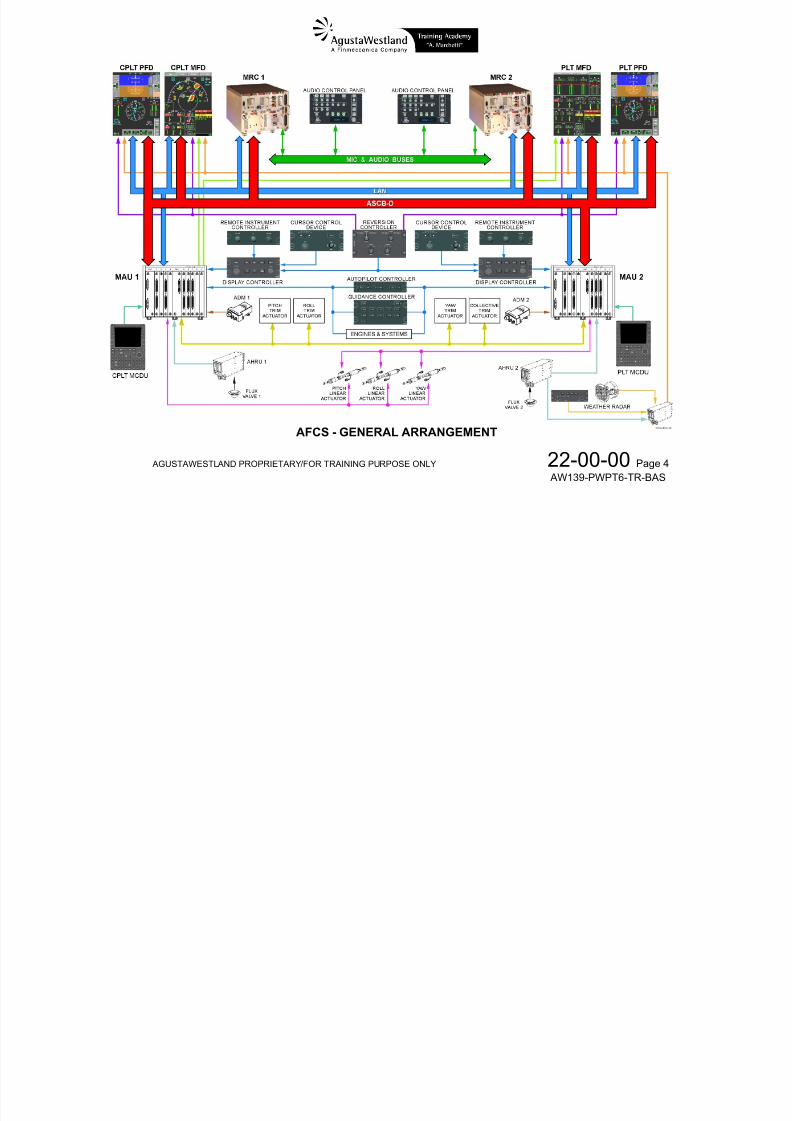
AFCS - GENERAL ARRANGEMENT
7/22/2019 Aw139 Pwpt6 Tr Bas Lowres
http://slidepdf.com/reader/full/aw139-pwpt6-tr-bas-lowres 101/1016
AGUSTAWESTLAND PROPRIETARY/FOR TRAINING PURPOSE ONLY 22-00-00 Page 5
AW139-PWPT6-TR-BAS
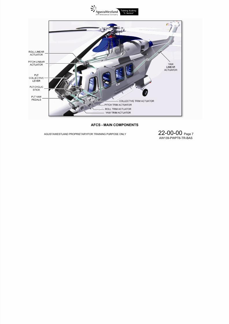
AFCS – MAIN COMPONENTS
The AFCS consists of the following main components:
four AFCS modules located inside the MAUs (twomodules in each MAU)

7/22/2019 Aw139 Pwpt6 Tr Bas Lowres
http://slidepdf.com/reader/full/aw139-pwpt6-tr-bas-lowres 102/1016
AGUSTAWESTLAND PROPRIETARY/FOR TRAINING PURPOSE ONLY 22-00-00 Page 6
AW139-PWPT6-TR-BAS
modules in each MAU)
one Autopilot Controller
one Guidance Controller
three sets of dual Linear Actuators
four Trim Actuators control switches on both cyclic sticks, both collective
levers, both yaw pedals and on the central console
AFCS indications are provided on the Display Units.
The following systems provide the data necessary for AFCS
operation: both ADS1 and ADS2
both AHRS1 and AHRS2
the Standby Instrument
both Radar Altimeter 1 and Radar Altimeter 2
both VHF NAV1 and VHF NAV2
both FMS1 and FMS2
7/22/2019 Aw139 Pwpt6 Tr Bas Lowres
http://slidepdf.com/reader/full/aw139-pwpt6-tr-bas-lowres 103/1016
AGUSTAWESTLAND PROPRIETARY/FOR TRAINING PURPOSE ONLY 22-00-00 Page 7
AW139-PWPT6-TR-BAS
AFCS - MAIN COMPONENTS
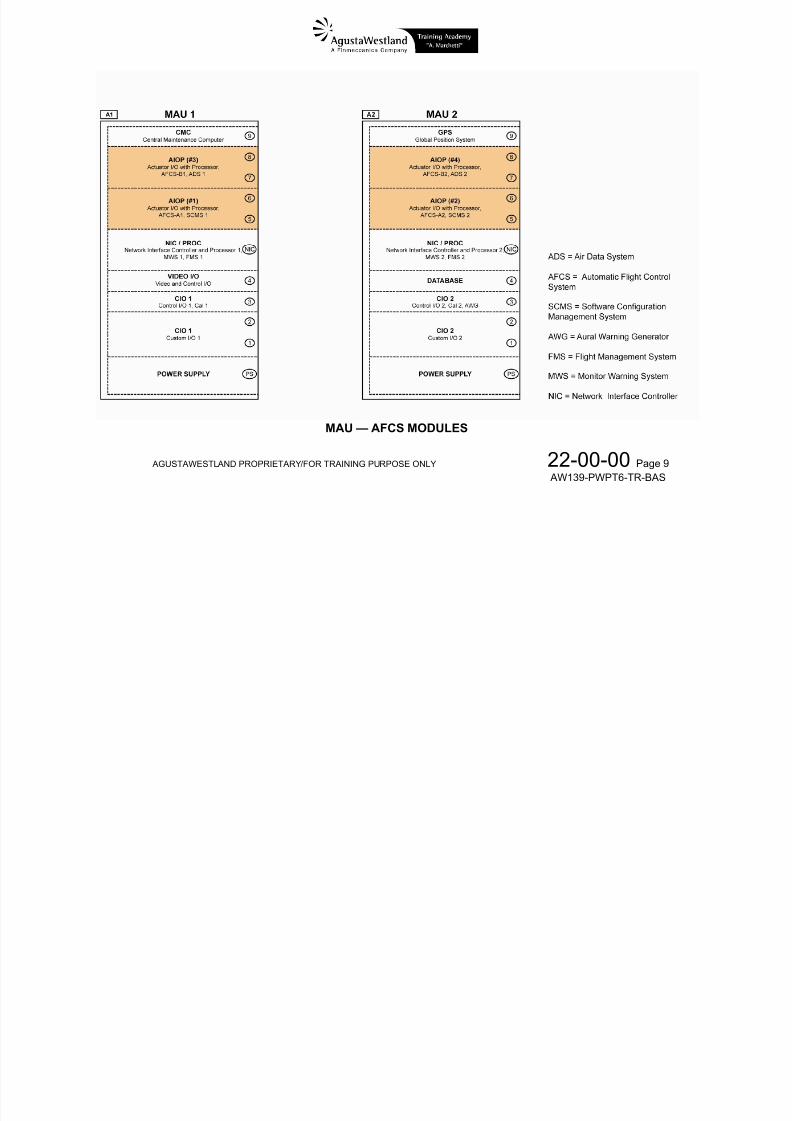
MODULAR AVIONIC UNIT (MAU) – GENERAL
Two AFCS modules are installed in each Modular Avionic Unit
(MAU) to perform AFCS computations, output commands andindication data and perform system monitoring.
7/22/2019 Aw139 Pwpt6 Tr Bas Lowres
http://slidepdf.com/reader/full/aw139-pwpt6-tr-bas-lowres 104/1016
AGUSTAWESTLAND PROPRIETARY/FOR TRAINING PURPOSE ONLY 22-00-00 Page 8
AW139-PWPT6-TR-BAS
The two AFCS modules —named Actuator Input/Output withProcessor (AIOP) modules— in MAU1 are part of AFCS1(AP1, FD1); the two AIOP modules in MAU2 are part of
AFCS2 (AP2, FD2).This makes the AFCS a dual-redundant computer system
(AFCS1 and AFCS2) and each AFCS dual-redundant inside(channel A and channel B).
The two modules of an AFCS share the tasks andcontinuously monitor each other performances to positivelyidentify any internal failure and, if the case, disengageautomatically.

7/22/2019 Aw139 Pwpt6 Tr Bas Lowres
http://slidepdf.com/reader/full/aw139-pwpt6-tr-bas-lowres 105/1016
AGUSTAWESTLAND PROPRIETARY/FOR TRAINING PURPOSE ONLY 22-00-00 Page 9
AW139-PWPT6-TR-BAS
MAU — AFCS MODULES
7/22/2019 Aw139 Pwpt6 Tr Bas Lowres
http://slidepdf.com/reader/full/aw139-pwpt6-tr-bas-lowres 106/1016
AGUSTAWESTLAND PROPRIETARY/FOR TRAINING PURPOSE ONLY 22-00-00 Page 10
AW139-PWPT6-TR-BAS
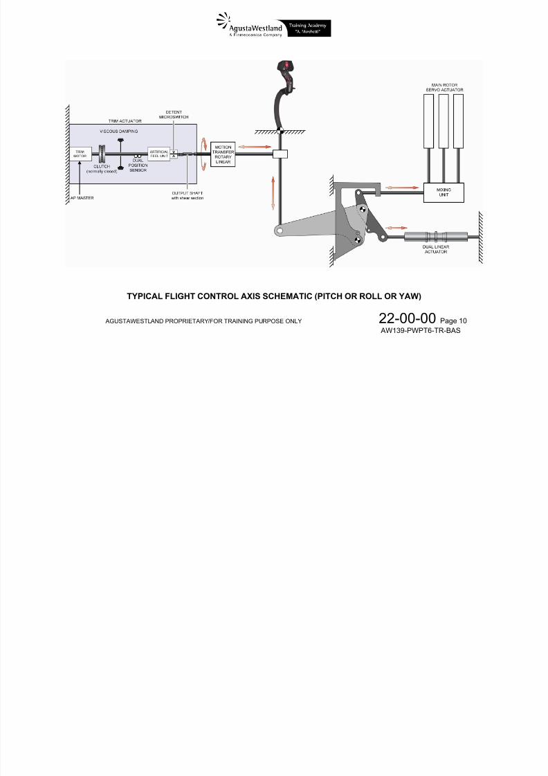
TYPICAL FLIGHT CONTROL AXIS SCHEMATIC (PITCH OR ROLL OR YAW)
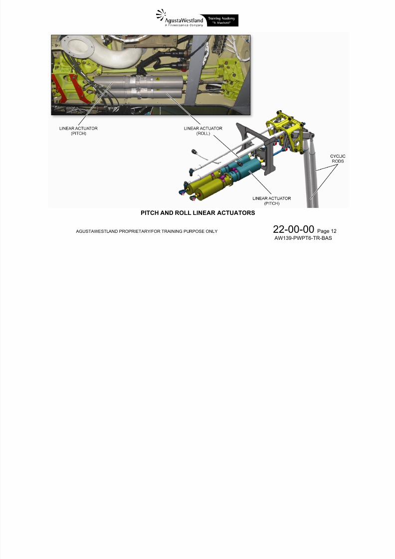
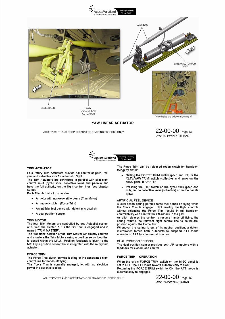
LINEAR ACTUATOR
Three sets of dual Linear Actuators provide limited controlinputs to pitch, roll and yaw axis flight control lines in serieswith pilot input (see chapter 67-00).Each set is connected to the relevant axis flight control line
7/22/2019 Aw139 Pwpt6 Tr Bas Lowres
http://slidepdf.com/reader/full/aw139-pwpt6-tr-bas-lowres 107/1016
AGUSTAWESTLAND PROPRIETARY/FOR TRAINING PURPOSE ONLY 22-00-00 Page 11
AW139-PWPT6-TR-BAS
through a dual-action bellcrank that permits summing ofactuator inputs to pilot inputs as well as preventing a Linear
Actuator mechanical failure from losing pilot manual control onthat axis.
Each dual Linear Actuator set incorporates two identical andindependent electrical motors, one controlled by AP 1 and onecontrolled by AP 2 via dedicated digital buses (CAN Bus).They are also called “smart” linear actuators since theyinclude a microprocessor to internally close the servo loop onthe position command from the on-side MAU.Each brushless motor drives a ball-screw which displaces theflight control line.
Each linear actuator includes an integrity centering function toprotect against runaway failure modes.
During normal operation with both Autopilots engaged, each AP outputs 50% of the computed input for an axis.In case of single AP operation, 100% of the computed input is
provided to the on-side Linear Actuator: in this case the totalauthority of the control is reduced to a half, resulting in adegradation of the system performance.

7/22/2019 Aw139 Pwpt6 Tr Bas Lowres
http://slidepdf.com/reader/full/aw139-pwpt6-tr-bas-lowres 108/1016
AGUSTAWESTLAND PROPRIETARY/FOR TRAINING PURPOSE ONLY 22-00-00 Page 12
AW139-PWPT6-TR-BAS
PITCH AND ROLL LINEAR ACTUATORS
7/22/2019 Aw139 Pwpt6 Tr Bas Lowres
http://slidepdf.com/reader/full/aw139-pwpt6-tr-bas-lowres 109/1016
AGUSTAWESTLAND PROPRIETARY/FOR TRAINING PURPOSE ONLY 22-00-00 Page 13
AW139-PWPT6-TR-BAS
YAW LINEAR ACTUATOR
7/22/2019 Aw139 Pwpt6 Tr Bas Lowres
http://slidepdf.com/reader/full/aw139-pwpt6-tr-bas-lowres 110/1016
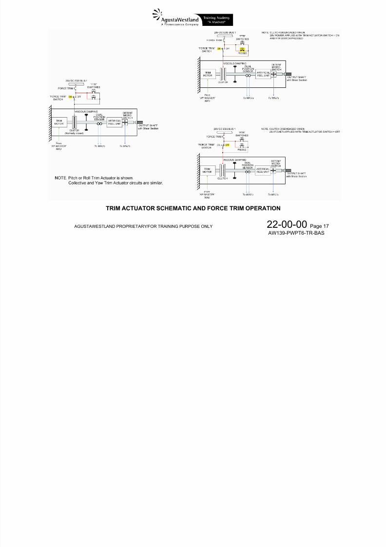
In a hands-off flight, as long as the pilot holds an FTR switchpressed, on the relevant axis:
The Force Trim clutch is disengaged Pilot is temporarily flying hands-on SAS

7/22/2019 Aw139 Pwpt6 Tr Bas Lowres
http://slidepdf.com/reader/full/aw139-pwpt6-tr-bas-lowres 111/1016
AGUSTAWESTLAND PROPRIETARY/FOR TRAINING PURPOSE ONLY 22-00-00 Page 15
AW139-PWPT6-TR-BAS
The Linear Actuators are centered
If a FD mode is engaged, the AP ignores the FDcommands
When pilot releases the FTR switch, on the relevant axis: The Force Trim clutch is re-engaged
The ATT mode reference value is reset to the presentattitude
If a FD mode is engaged, the reference targetparameter is reset to the present value (eg. IAS, VS,
Radio Height, etc) Pilot returns to hands-off flight
When the Force Trim clutch is disengaged then:
the force feel system is disengaged
the Trim Actuator drive is disengaged
the Autotrim is disabled
Upon detection of the detent switch activation (Pilot movingcontrols without disengaging the Force Trim), the AFCSdisables commands to the respective trim motors.

7/22/2019 Aw139 Pwpt6 Tr Bas Lowres
http://slidepdf.com/reader/full/aw139-pwpt6-tr-bas-lowres 112/1016
AGUSTAWESTLAND PROPRIETARY/FOR TRAINING PURPOSE ONLY 22-00-00 Page 16
AW139-PWPT6-TR-BAS
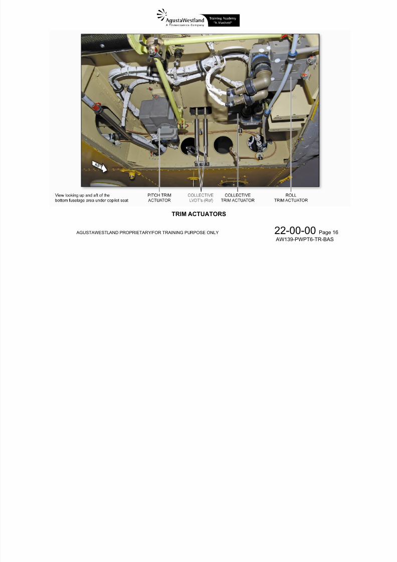
TRIM ACTUATORS

7/22/2019 Aw139 Pwpt6 Tr Bas Lowres
http://slidepdf.com/reader/full/aw139-pwpt6-tr-bas-lowres 113/1016
AGUSTAWESTLAND PROPRIETARY/FOR TRAINING PURPOSE ONLY 22-00-00 Page 17
AW139-PWPT6-TR-BAS
TRIM ACTUATOR SCHEMATIC AND FORCE TRIM OPERATION
AFCS – CONTROLS AND INDICATORS
The following flight deck components constitute pilotinterfaces for input to the AFCS:
Autopilot Controller
Guidance Controller (Flight Director control panel)
Guidance Controller (status lights)
PFD (annunciators, guidance cues)
MFD (CAS messages and Synoptic)
If an AFCS problem is obvious from CAS cautions, failureindications or aircraft response the autopilot controller should

7/22/2019 Aw139 Pwpt6 Tr Bas Lowres
http://slidepdf.com/reader/full/aw139-pwpt6-tr-bas-lowres 114/1016
AGUSTAWESTLAND PROPRIETARY/FOR TRAINING PURPOSE ONLY 22-00-00 Page 18
AW139-PWPT6-TR-BAS
Guidance Controller (Flight Director control panel)
Cyclic, pedal and collective Beep switches
Cyclic, pedal and collective Force Trim Release (FTR)switches
Cyclic, pedal and collective Force Trim enable switcheson MISC panel
AP1 & AP2 disconnect switch (SAS REL) on cyclicgrips
Remote Flight Director standby (FD STBY) button
Go-Around (GA) button on Collective levers
Guidance reference inputs are also provided via:
Display Controller (DC)
Remote Instrument Controller (RIC)
Cursor Control Device (CCD)
Multifunction Display Control Unit (MCDU)
AFCS indications are provided on
Autopilot Controller (status lights)
indications or aircraft response, the autopilot controller shouldbe used to deselect the faulty channel and the individualbehaviour of AP 1 and AP 2 observed.
Illumination of the relevant Autopilot AP channel lights and the
display of CAS captions should be used to make a positivediagnosis before, for example, disengaging an AFCS channel.
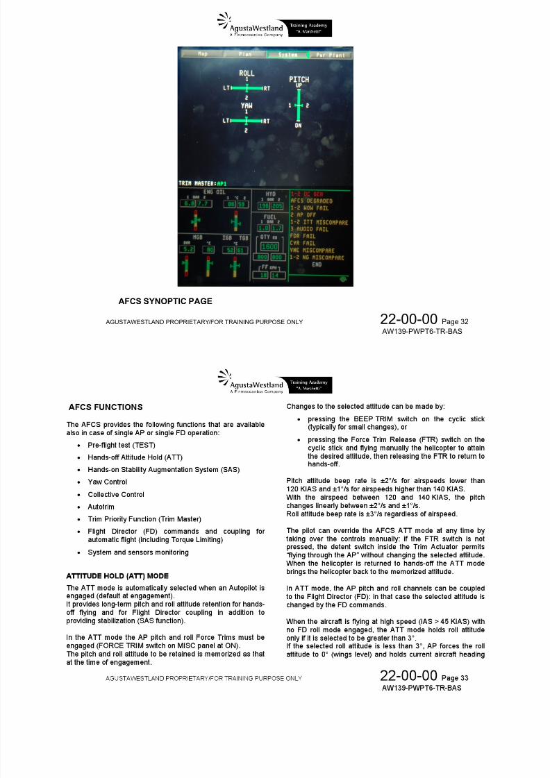
In case of an un-commanded aircraft disturbance oroscillation, occurring without an AFCS caution, the pilotshould selectively disengage and re-engage individualchannel in order to determine and isolate a potential non-annunciated AFCS fault. This can be achieved through theuse of the autopilot channel pushbuttons (AP 1, AP 2) andmonitoring of the trim display (select SYSTEM, FLIGHT CTRLon MFD to display the AFCS synoptic page) and aircraftresponse.
AUTOPILOT CONTROLS
AUTOPILOT CONTROLLER
1. AP 1 push-buttonPRESSED...….… Illuminates the green annunciator light and engages the AP no.1.
P hi h b i i i h h i li h d di h AP 1

7/22/2019 Aw139 Pwpt6 Tr Bas Lowres
http://slidepdf.com/reader/full/aw139-pwpt6-tr-bas-lowres 115/1016
AGUSTAWESTLAND PROPRIETARY/FOR TRAINING PURPOSE ONLY 22-00-00 Page 19
AW139-PWPT6-TR-BAS
Pushing the button again extinguishes the green annunciator light and disengages the AP no.1.
NOTE. When the pilot engages AP 1 then:1) ATTITUDE mode is set as default mode2) the yaw control functions are activated3) the SAS mode is forced if the cyclic FORCE TRIM switch is set to OFF.The AP can operate both with and without FD guidance. In normal operation, both AP 1 and
AP 2 are engaged in order to supply full dual system performance while coupled to FD.
2. AP 2 push-buttonPRESSED...….… Illuminates the green annunciator light and engages the AP no.2.
Pushing the button again extinguishes the green annunciator light and disengages the AP no.2.
NOTE. See NOTE for AP 1.
3. TEST push-buttonPRESSED...….… Illuminates the green annunciator light and starts the Built-In Test (BIT).
Pushing the button again extinguishes the green annunciator light and exits the BIT.
4. CPL push-buttonNOTE. When a FD mode is engaged, FD automatically couples to AP and the CPL green annunciator
illuminates.
PRESSED...….… When green annunciator is illuminated, uncouples the FD from AP and the annunciator extinguishes.
Pushing the CPL button again illuminates the green annunciator light and manually re-couples the FD tothe AP.
5. SAS push-buttonPRESSED...….… Illuminates the green annunciator light and engages the SAS mode.
NOTE. The SAS and ATT buttons are mutually exclusive and are used to select the SAS or ATTITUDEd f i f h AFCS
7/22/2019 Aw139 Pwpt6 Tr Bas Lowres
http://slidepdf.com/reader/full/aw139-pwpt6-tr-bas-lowres 116/1016
AGUSTAWESTLAND PROPRIETARY/FOR TRAINING PURPOSE ONLY 22-00-00 Page 20
AW139-PWPT6-TR-BAS
mode of operation of the AFCS.When the cyclic FORCE TRIM switch is set to OFF, the AP engages with the SAS mode active.
6. ATT push-button
PRESSED...….… Illuminates the green annunciator light and engages the ATTITUDE mode.NOTE. The SAS and ATT buttons are mutually exclusive and are used to select the SAS or ATTITUDE
mode of operation of the AFCS.The ATT mode is automatically engaged if at least one AP is engaged and the cyclic FORCETRIM switch is set to ON.The ATT mode disengages if the pilot:1) engages the SAS mode or2) sets the cyclic FORCE TRIM switch to OFF or3) disengages both AP 1 and AP 2.

7/22/2019 Aw139 Pwpt6 Tr Bas Lowres
http://slidepdf.com/reader/full/aw139-pwpt6-tr-bas-lowres 117/1016
AGUSTAWESTLAND PROPRIETARY/FOR TRAINING PURPOSE ONLY 22-00-00 Page 21
AW139-PWPT6-TR-BAS
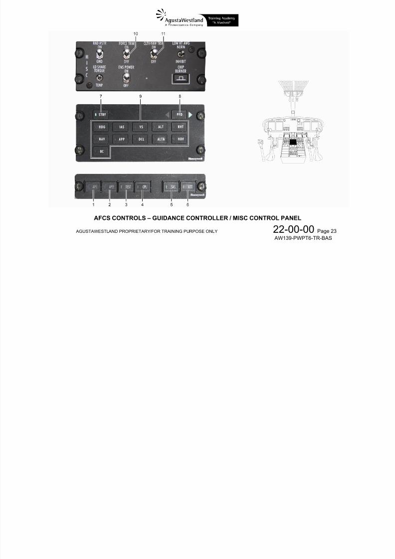
AFCS CONTROLS – AUTOPILOT CONTROLLER
GUIDANCE CONTROLLER
7. STBY pushbuttonPRESSED...….… Illuminates the green annunciator light and cancels any selected active flight director modes.
8. PFD pushbuttonPRESSED Selects which PFD (left or right) supplies source data that is used by both flight directors and toggles the

7/22/2019 Aw139 Pwpt6 Tr Bas Lowres
http://slidepdf.com/reader/full/aw139-pwpt6-tr-bas-lowres 118/1016
AGUSTAWESTLAND PROPRIETARY/FOR TRAINING PURPOSE ONLY 22-00-00 Page 22
AW139-PWPT6-TR-BAS
PRESSED...….… Selects which PFD (left or right) supplies source data that is used by both flight directors and toggles theassociated green arrow annunciator located on each side of the PFD button. The illuminated arrowindicates the selected PFD.
9. FD Mode pushbuttonsPRESSED...….… Illuminate the relevant green annunciator light and engage or arm the relevant Flight Director mode.
Pushing any button again extinguishes the relevant green annunciator light and disengages the relevantFlight Director mode.
MISC CONTROL PANEL
10. FORCE TRIM switch
OFF ……..……… Disengages the cyclic Force Trims (Pitch and Roll) and disables ATT mode of the AP
ON ……………… Engages the cyclic Force Trims (Pitch and Roll) and enables ATT mode of the AP
11. CLTV / YAW TRIM switch
OFF ……..……… Disengages the collective and pedal Force Trims
ON ……………… Engages the collective and pedal Force Trims

7/22/2019 Aw139 Pwpt6 Tr Bas Lowres
http://slidepdf.com/reader/full/aw139-pwpt6-tr-bas-lowres 119/1016
AGUSTAWESTLAND PROPRIETARY/FOR TRAINING PURPOSE ONLY 22-00-00 Page 23
AW139-PWPT6-TR-BAS
AFCS CONTROLS – GUIDANCE CONTROLLER / MISC CONTROL PANEL
COLLECTIVE LEVER
12. BEEP CLTV / YAW TRIM switch (on PLT and CPLT collective grip)
DN / UP ………… Allows trimming the collective axis if the CLTV / YAW TRIM switch on Miscellaneous control panel is ON.Changes the reference target parameter value if a FD collective mode is engaged.
L / R ……………. Allows trimming the yaw axis if the CLTV / YAW TRIM switch on Miscellaneous control panel is ON

7/22/2019 Aw139 Pwpt6 Tr Bas Lowres
http://slidepdf.com/reader/full/aw139-pwpt6-tr-bas-lowres 120/1016
AGUSTAWESTLAND PROPRIETARY/FOR TRAINING PURPOSE ONLY 22-00-00 Page 24
AW139-PWPT6-TR-BAS
13. FTR (Force Trim Release) push-button switch (on PLT and CPLT collective grip)
PRESSED .…….. Disengages the collective Force Trim suspending collective trimming and force feel
RELEASED …… Re-engages the collective Force Trim restoring collective trimming and force feel.If a FD collective mode is engaged, the reference target parameter is reset to the current value
14. GA (GO AROUND) mode push-button switch (on PLT and CPLT collective grip)
PRESSED .…….. Engages the GA mode

7/22/2019 Aw139 Pwpt6 Tr Bas Lowres
http://slidepdf.com/reader/full/aw139-pwpt6-tr-bas-lowres 121/1016
AGUSTAWESTLAND PROPRIETARY/FOR TRAINING PURPOSE ONLY 22-00-00 Page 25
AW139-PWPT6-TR-BAS
AFCS CONTROLS – COLLECTIVE LEVER
CYCLIC STICK
15. BEEP TRIM switch (on PLT and CPLT cyclic grip)
DN / UP ………… Allows trimming the pitch axis if the FORCE TRIM switch on Miscellaneous control panel is ON and ATTmode is selected on AP
L / R ……………. Allows trimming the roll axis if the FORCE TRIM switch on Miscellaneous control panel is ON and ATTmode is selected on AP
7/22/2019 Aw139 Pwpt6 Tr Bas Lowres
http://slidepdf.com/reader/full/aw139-pwpt6-tr-bas-lowres 122/1016
AGUSTAWESTLAND PROPRIETARY/FOR TRAINING PURPOSE ONLY 22-00-00 Page 26
AW139-PWPT6-TR-BAS
mode is selected on AP
PRESSED .…….. Engages the HOV mode on FD (4-Axis Enhanced FD only)
16. FTR push-button switch (on PLT and CPLT cyclic grip)
PRESSED ……… Disengages the cyclic Force Trims (Pitch and Roll) suspending collective trimming and force feel.Re-centers the Pitch and Roll Linear Actuators.
RELEASED ……. Re-engages the cyclic Force Trims (Pitch and Roll) restoring cyclic trimming and force feel.If a FD pitch or roll mode is engaged, the relevant reference target parameter is reset to the current value
17. FD STBY (Flight Director Standby) switch (on PLT and CPLT cyclic grip)
PRESSED ……… Illuminates the green annunciator light and cancels any selected active flight director modes
18. SAS REL push-button switch (on PLT and CPLT cyclic grip)
PRESSED ……… Disengages both Autopilots (AP 1 and AP 2)

7/22/2019 Aw139 Pwpt6 Tr Bas Lowres
http://slidepdf.com/reader/full/aw139-pwpt6-tr-bas-lowres 123/1016
AGUSTAWESTLAND PROPRIETARY/FOR TRAINING PURPOSE ONLY 22-00-00 Page 27
AW139-PWPT6-TR-BAS
AFCS CONTROLS – CYCLIC STICK
PEDALS
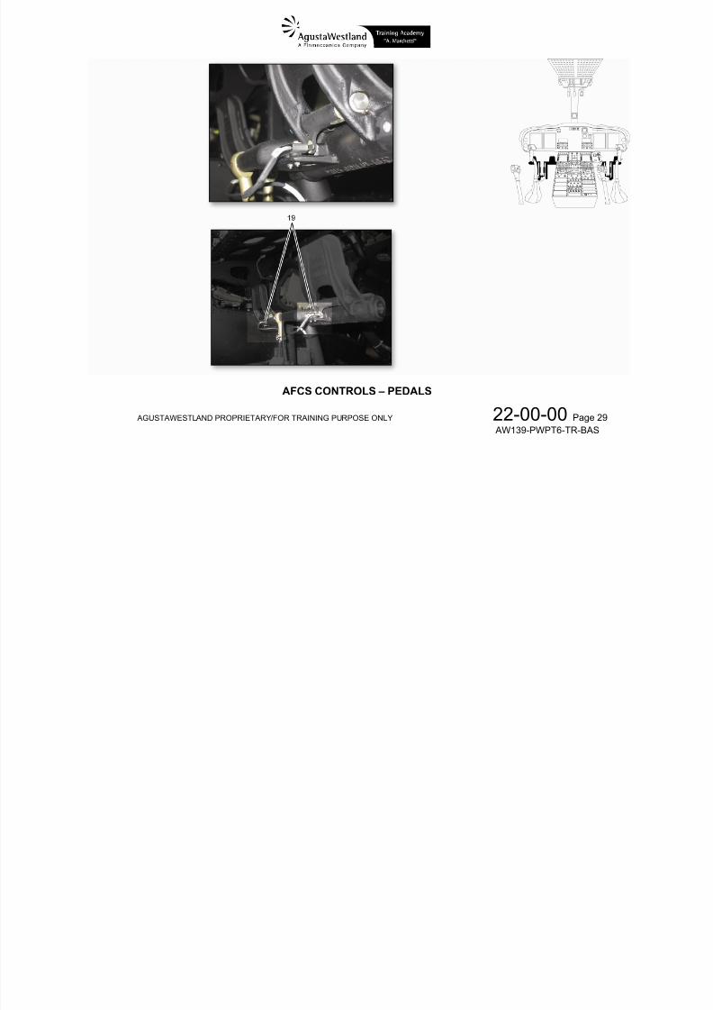
19. YAW force trim release switch (on PLT and CPLT pedals)
PRESSED ……… Disengages the pedal Force Trim (Yaw) suspending yaw trimming and force feel.Re-centers the Yaw Linear Actuator
RELEASED ……. Re-engages the pedal Force Trims (Yaw) restoring yaw trimming and force feel
7/22/2019 Aw139 Pwpt6 Tr Bas Lowres
http://slidepdf.com/reader/full/aw139-pwpt6-tr-bas-lowres 124/1016
AGUSTAWESTLAND PROPRIETARY/FOR TRAINING PURPOSE ONLY 22-00-00 Page 28
AW139-PWPT6-TR-BAS
7/22/2019 Aw139 Pwpt6 Tr Bas Lowres
http://slidepdf.com/reader/full/aw139-pwpt6-tr-bas-lowres 125/1016
AGUSTAWESTLAND PROPRIETARY/FOR TRAINING PURPOSE ONLY 22-00-00 Page 29
AW139-PWPT6-TR-BAS
AFCS CONTROLS – PEDALS
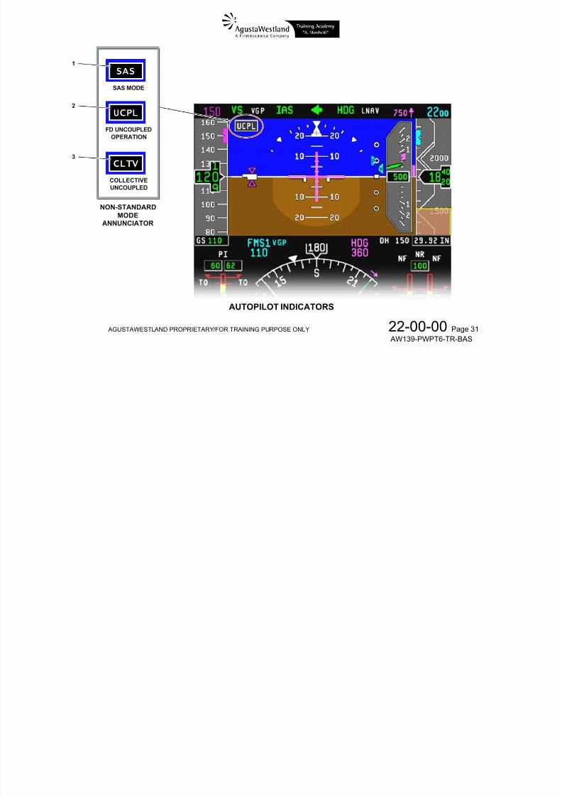
AUTOPILOT INDICATORS
1. SAS annunciatorIn view...….… Indicates that AP is in SAS mode
2. UCPL annunciatorI i I di t th t Fli ht Di t i l d ( ll ) f th AP
7/22/2019 Aw139 Pwpt6 Tr Bas Lowres
http://slidepdf.com/reader/full/aw139-pwpt6-tr-bas-lowres 126/1016
AGUSTAWESTLAND PROPRIETARY/FOR TRAINING PURPOSE ONLY 22-00-00 Page 30
AW139-PWPT6-TR-BAS
In view...….… Indicates that Flight Director is uncoupled (all axes) from the AP
NOTE. The UCPL annunciator is not in view when the AP is in SAS mode
3. CLTV annunciatorIn view...….… Indicates that Flight Director is uncoupled from the AP on the Collective axis only
NOTE. The CLTV annunciator is not in view when the AP is in SAS mode or FD is uncoupled on all axes
UCPL
S S1
2
SAS MODE

7/22/2019 Aw139 Pwpt6 Tr Bas Lowres
http://slidepdf.com/reader/full/aw139-pwpt6-tr-bas-lowres 127/1016
AGUSTAWESTLAND PROPRIETARY/FOR TRAINING PURPOSE ONLY 22-00-00 Page 31
AW139-PWPT6-TR-BAS
UCPL
CLTV3
FD UNCOUPLEDOPERATION
COLLECTIVEUNCOUPLED
NON-STANDARDMODE
ANNUNCIATOR
AUTOPILOT INDICATORS
7/22/2019 Aw139 Pwpt6 Tr Bas Lowres
http://slidepdf.com/reader/full/aw139-pwpt6-tr-bas-lowres 128/1016
AGUSTAWESTLAND PROPRIETARY/FOR TRAINING PURPOSE ONLY 22-00-00 Page 32
AW139-PWPT6-TR-BAS
AFCS SYNOPTIC PAGE
7/22/2019 Aw139 Pwpt6 Tr Bas Lowres
http://slidepdf.com/reader/full/aw139-pwpt6-tr-bas-lowres 129/1016
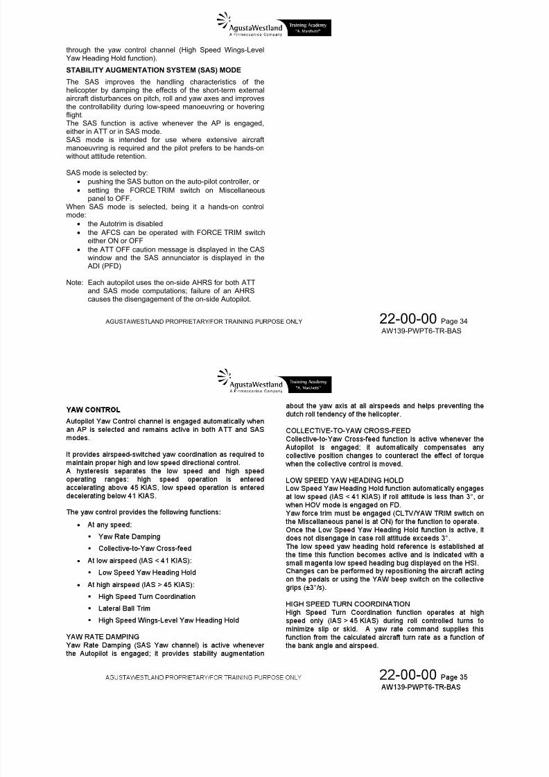
through the yaw control channel (High Speed Wings-LevelYaw Heading Hold function).
STABILITY AUGMENTATION SYSTEM (SAS) MODE
The SAS improves the handling characteristics of thehelicopter by damping the effects of the short-term externalaircraft disturbances on pitch, roll and yaw axes and improvesthe controllability during low-speed manoeuvring or hoveringflight
7/22/2019 Aw139 Pwpt6 Tr Bas Lowres
http://slidepdf.com/reader/full/aw139-pwpt6-tr-bas-lowres 130/1016
AGUSTAWESTLAND PROPRIETARY/FOR TRAINING PURPOSE ONLY 22-00-00 Page 34
AW139-PWPT6-TR-BAS
flight.The SAS function is active whenever the AP is engaged,either in ATT or in SAS mode.SAS mode is intended for use where extensive aircraftmanoeuvring is required and the pilot prefers to be hands-onwithout attitude retention.
SAS mode is selected by: pushing the SAS button on the auto-pilot controller, or setting the FORCE TRIM switch on Miscellaneous
panel to OFF.
When SAS mode is selected, being it a hands-on controlmode: the Autotrim is disabled the AFCS can be operated with FORCE TRIM switch
either ON or OFF the ATT OFF caution message is displayed in the CAS
window and the SAS annunciator is displayed in the ADI (PFD)
Note: Each autopilot uses the on-side AHRS for both ATTand SAS mode computations; failure of an AHRScauses the disengagement of the on-side Autopilot.
7/22/2019 Aw139 Pwpt6 Tr Bas Lowres
http://slidepdf.com/reader/full/aw139-pwpt6-tr-bas-lowres 131/1016
7/22/2019 Aw139 Pwpt6 Tr Bas Lowres
http://slidepdf.com/reader/full/aw139-pwpt6-tr-bas-lowres 132/1016

7/22/2019 Aw139 Pwpt6 Tr Bas Lowres
http://slidepdf.com/reader/full/aw139-pwpt6-tr-bas-lowres 133/1016
AGUSTAWESTLAND PROPRIETARY/FOR TRAINING PURPOSE ONLY 22-00-00 Page 37
AW139-PWPT6-TR-BAS
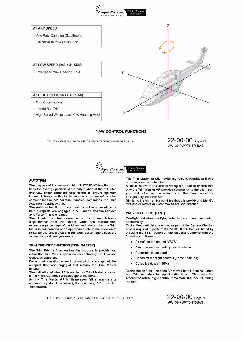
YAW CONTROL FUNCTIONS
7/22/2019 Aw139 Pwpt6 Tr Bas Lowres
http://slidepdf.com/reader/full/aw139-pwpt6-tr-bas-lowres 134/1016
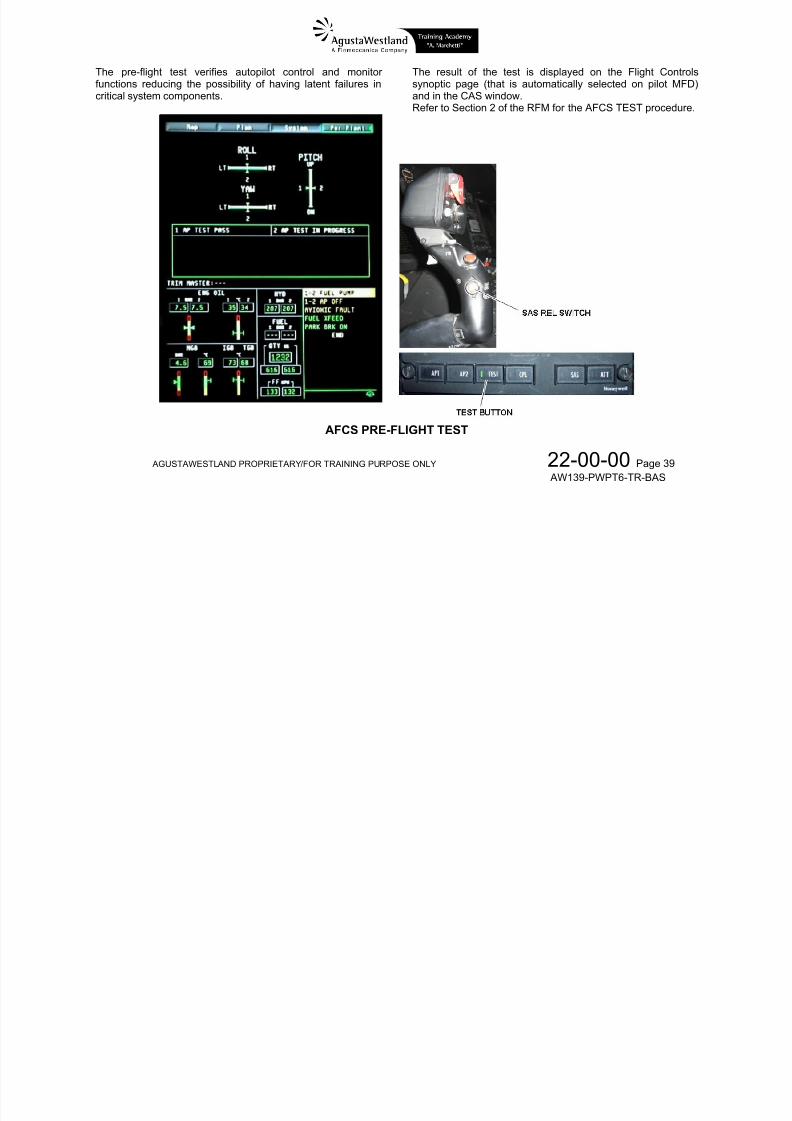
The pre-flight test verifies autopilot control and monitorfunctions reducing the possibility of having latent failures incritical system components.
The result of the test is displayed on the Flight Controlssynoptic page (that is automatically selected on pilot MFD)and in the CAS window.Refer to Section 2 of the RFM for the AFCS TEST procedure.

7/22/2019 Aw139 Pwpt6 Tr Bas Lowres
http://slidepdf.com/reader/full/aw139-pwpt6-tr-bas-lowres 135/1016
AGUSTAWESTLAND PROPRIETARY/FOR TRAINING PURPOSE ONLY 22-00-00 Page 39
AW139-PWPT6-TR-BAS
AFCS PRE-FLIGHT TEST
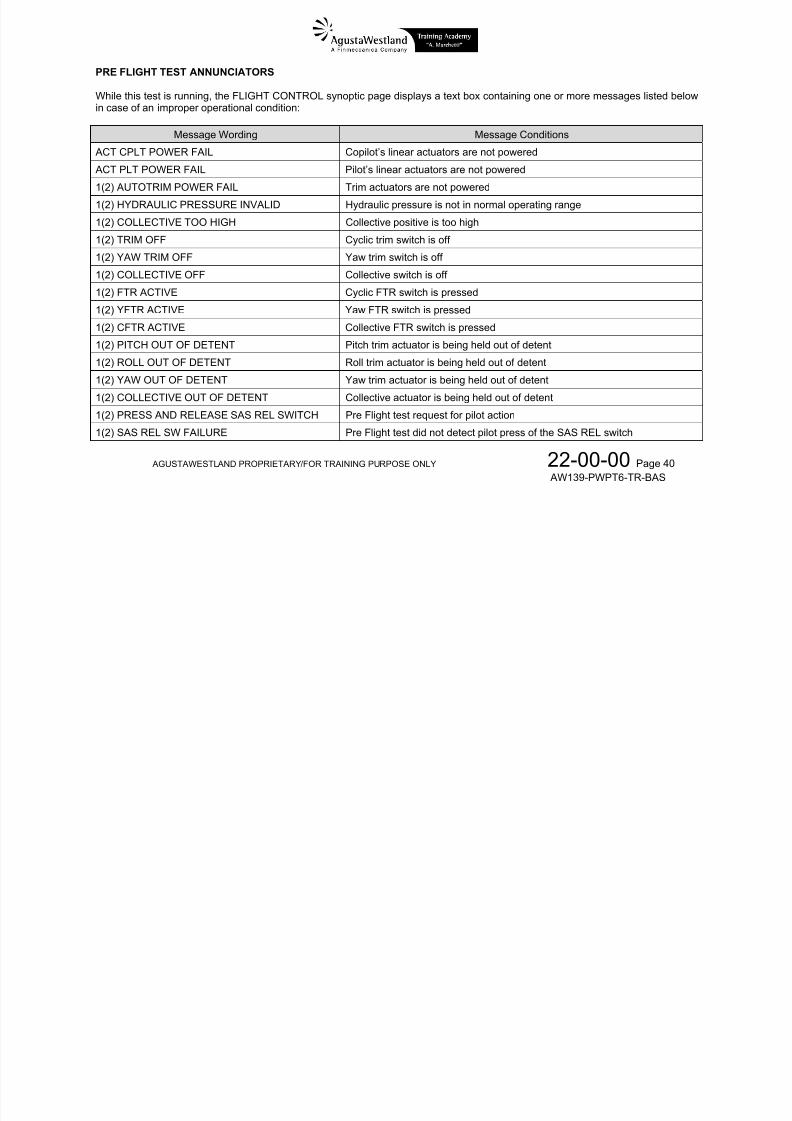
PRE FLIGHT TEST ANNUNCIATORS
While this test is running, the FLIGHT CONTROL synoptic page displays a text box containing one or more messages listed belowin case of an improper operational condition:
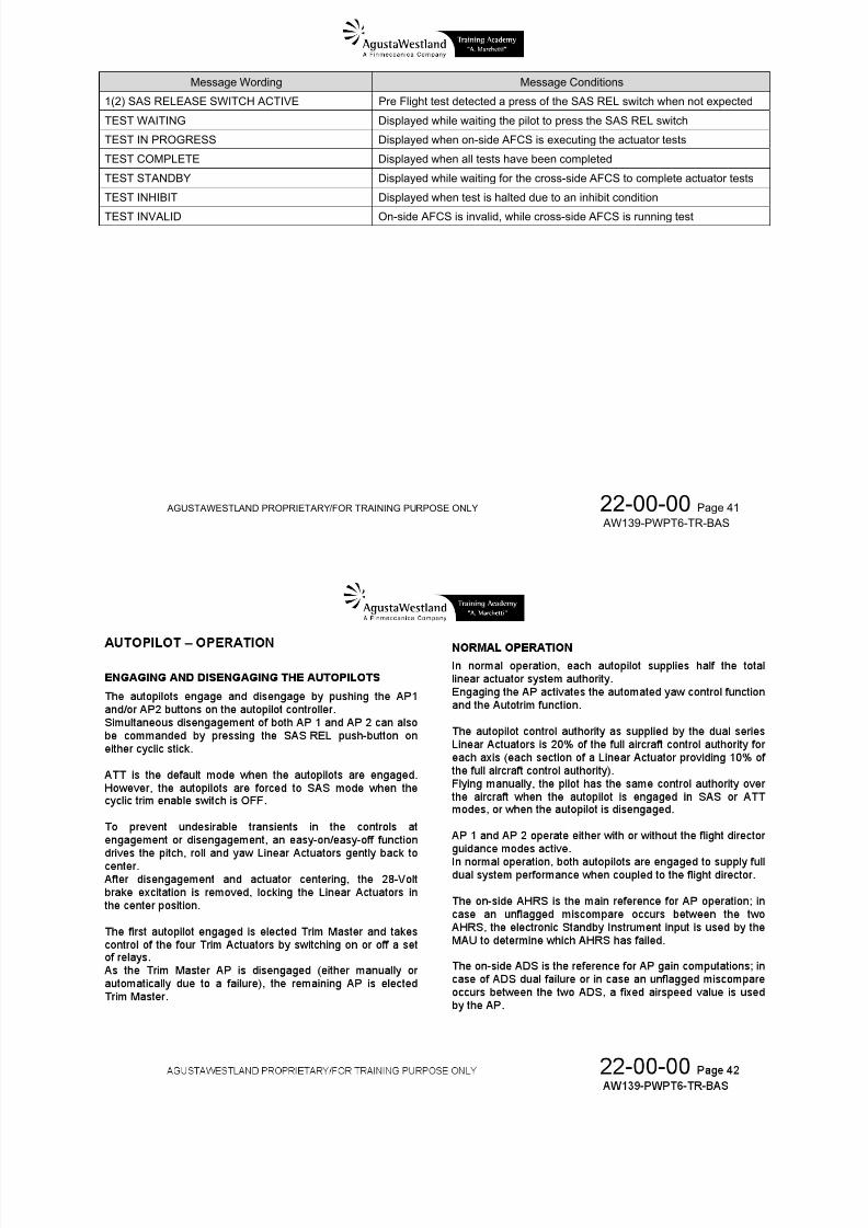
Message Wording Message Conditions
ACT CPLT POWER FAIL Copilot’s linear actuators are not powered
ACT PLT POWER FAIL Pilot’s linear actuators are not powered
7/22/2019 Aw139 Pwpt6 Tr Bas Lowres
http://slidepdf.com/reader/full/aw139-pwpt6-tr-bas-lowres 136/1016
AGUSTAWESTLAND PROPRIETARY/FOR TRAINING PURPOSE ONLY 22-00-00 Page 40
AW139-PWPT6-TR-BAS
p
1(2) AUTOTRIM POWER FAIL Trim actuators are not powered
1(2) HYDRAULIC PRESSURE INVALID Hydraulic pressure is not in normal operating range
1(2) COLLECTIVE TOO HIGH Collective positive is too high
1(2) TRIM OFF Cyclic trim switch is off
1(2) YAW TRIM OFF Yaw trim switch is off
1(2) COLLECTIVE OFF Collective switch is off
1(2) FTR ACTIVE Cyclic FTR switch is pressed
1(2) YFTR ACTIVE Yaw FTR switch is pressed
1(2) CFTR ACTIVE Collective FTR switch is pressed
1(2) PITCH OUT OF DETENT Pitch trim actuator is being held out of detent
1(2) ROLL OUT OF DETENT Roll trim actuator is being held out of detent
1(2) YAW OUT OF DETENT Yaw trim actuator is being held out of detent
1(2) COLLECTIVE OUT OF DETENT Collective actuator is being held out of detent
1(2) PRESS AND RELEASE SAS REL SWITCH Pre Flight test request for pilot action
1(2) SAS REL SW FAILURE Pre Flight test did not detect pilot press of the SAS REL switch
Message Wording Message Conditions
1(2) SAS RELEASE SWITCH ACTIVE Pre Flight test detected a press of the SAS REL switch when not expected
TEST WAITING Displayed while waiting the pilot to press the SAS REL switch
TEST IN PROGRESS Displayed when on-side AFCS is executing the actuator tests
TEST COMPLETE Displayed when all tests have been completed
TEST STANDBY Displayed while waiting for the cross-side AFCS to complete actuator tests

7/22/2019 Aw139 Pwpt6 Tr Bas Lowres
http://slidepdf.com/reader/full/aw139-pwpt6-tr-bas-lowres 137/1016
AGUSTAWESTLAND PROPRIETARY/FOR TRAINING PURPOSE ONLY 22-00-00 Page 41
AW139-PWPT6-TR-BAS
TEST INHIBIT Displayed when test is halted due to an inhibit condition
TEST INVALID On-side AFCS is invalid, while cross-side AFCS is running test

7/22/2019 Aw139 Pwpt6 Tr Bas Lowres
http://slidepdf.com/reader/full/aw139-pwpt6-tr-bas-lowres 138/1016

7/22/2019 Aw139 Pwpt6 Tr Bas Lowres
http://slidepdf.com/reader/full/aw139-pwpt6-tr-bas-lowres 139/1016
AGUSTAWESTLAND PROPRIETARY/FOR TRAINING PURPOSE ONLY 22-00-00 Page 43
AW139-PWPT6-TR-BAS
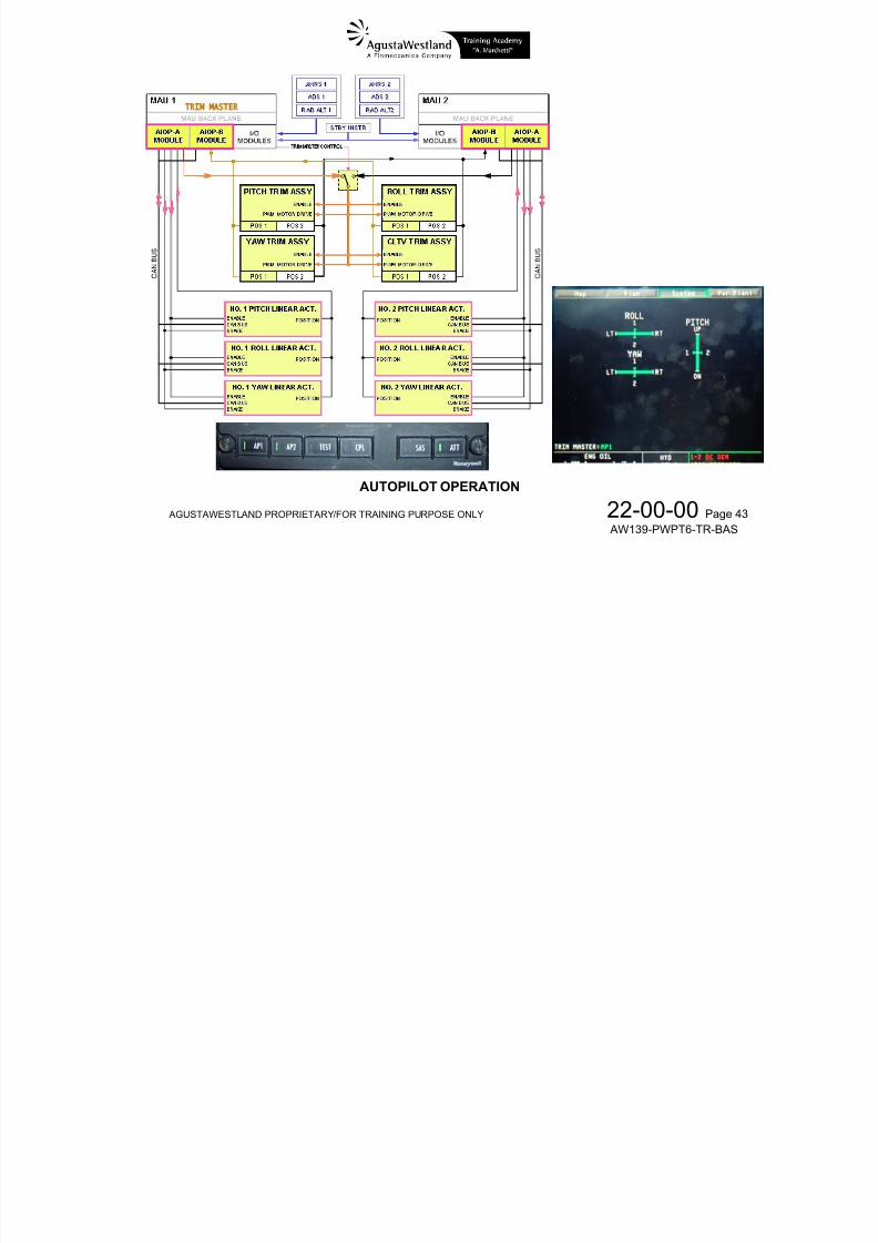
AUTOPILOT OPERATION
AUTOPILOT FAILURE
When detecting failure affecting mode integrity, the AP of theaffected single system disengages.
The following events also disengage the on-side AP on thecorresponding AHRS:
Invalid on-side attitude data
Invalid on-side attitude rate data
With the autopilots engaged, FTR switches, AP disengageswitches (SAS REL), detent switches and actuator circuitbreakers offer different ways to partially or completely overridethe AFCS.
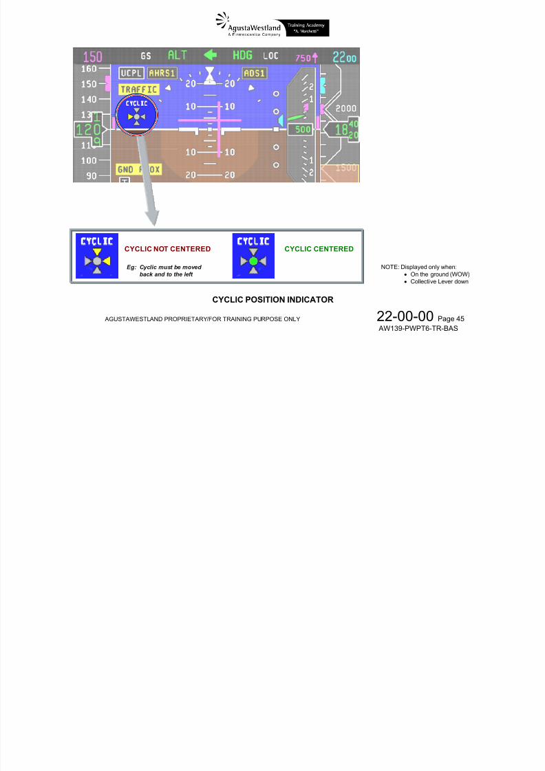
CYCLIC POSITION INDICATOR
The cyclic position indicator is displayed on the ADI to helppilot center the cyclic controls before starting the engines, toensure that the main rotor does not hit the static stops when
7/22/2019 Aw139 Pwpt6 Tr Bas Lowres
http://slidepdf.com/reader/full/aw139-pwpt6-tr-bas-lowres 140/1016
AGUSTAWESTLAND PROPRIETARY/FOR TRAINING PURPOSE ONLY 22-00-00 Page 44
AW139-PWPT6-TR-BAS
Invalid on-side yaw rate data
Failure of an AP is annunciated by CAS messages and the AUTOPILOT-AUTOPILOT aural warning message.
SINGLE AUTOPILOT OPERATION
With only one autopilot engaged, the single system operatesat full gain with half the dual system authority. When bothautopilots are engaged, each single system gain is reduced to
50% so that each system supplies half of the required input.This results in full gain control with twice the single systemauthority.Full yaw control and Autotrim functions are available also insingle system operation.
AUTOPILOT OVERRIDE
The pilot has full authority with the AP engaged or disengagedand can immediately override the AFCS at any time by simplytaking over the controls.
ensure that the main rotor does not hit the static stops whenrotating at low speed.The indicator is only displayed when the helicopter is on theground (WOW) with collective down (LVDT signal via EECs).Indication is taken from the position sensors located inside thepitch and roll Trim Actuators.The cyclic is centered when the indicator shows a green dot;amber arrows indicate which direction the cyclic stick must bemoved to center the controls.

7/22/2019 Aw139 Pwpt6 Tr Bas Lowres
http://slidepdf.com/reader/full/aw139-pwpt6-tr-bas-lowres 141/1016
AGUSTAWESTLAND PROPRIETARY/FOR TRAINING PURPOSE ONLY 22-00-00 Page 45
AW139-PWPT6-TR-BAS
CYCLIC CENTERED
Eg: Cyclic must be movedback and to the left
CYCLIC NOT CENTERED
CYCLIC POSITION INDICATOR
NOTE: Displayed only when: On the ground (WOW) Collective Lever down
AUTOPILOT FAILURES – CAS CAUTION MESSAGES
CAS CAPTION FAILURE DESCRIPTION PROCEDURE NAME AW139-RFM-4D
1(2) AP FAIL
+ aural message +
Associated autopilot failure AUTOPILOT FAIL

7/22/2019 Aw139 Pwpt6 Tr Bas Lowres
http://slidepdf.com/reader/full/aw139-pwpt6-tr-bas-lowres 142/1016
AGUSTAWESTLAND PROPRIETARY/FOR TRAINING PURPOSE ONLY 22-00-00 Page 46
AW139-PWPT6-TR-BAS
AFCS DEGRADED
Section 3
EMERGENCY ANDMALFUNCTIONPROCEDURES
1(2) AP P(R)(Y) FAIL
+ aural message
Pitch (Roll) (Yaw) axis of AP 1(2) uncommandeddisengagement
AUTOPILOT AXISDISENGAGE
1(2) AP OFF
+ aural message +
AFCS DEGRADED
Associated AP not switched ON AUTOPILOT OFF
1(2) AP P(R)(Y) OFF
+ aural message
Pitch (Roll) (Yaw) axis of AP 1(2) not engaged AUTOPILOT AXIS OFF
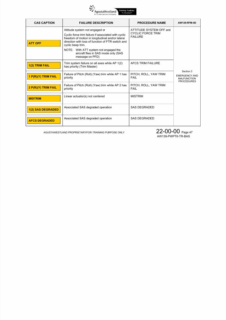
CAS CAPTION FAILURE DESCRIPTION PROCEDURE NAME AW139-RFM-4D
ATT OFF
Attitude system not engaged or
Cyclic force trim failure if associated with cyclicfreedom of motion in longitudinal and/or lateraldirection with loss of function of FTR switch andcyclic beep trim.
NOTE: With ATT system not engaged the
ATTITUDE SYSTEM OFF and
CYCLIC FORCE TRIMFAILURE
7/22/2019 Aw139 Pwpt6 Tr Bas Lowres
http://slidepdf.com/reader/full/aw139-pwpt6-tr-bas-lowres 143/1016
AGUSTAWESTLAND PROPRIETARY/FOR TRAINING PURPOSE ONLY 22-00-00 Page 47 AW139-PWPT6-TR-BAS
aircraft flies in SAS mode only (SASmessage on PFD)
Section 3
EMERGENCY ANDMALFUNCTIONPROCEDURES
1(2) TRIM FAILTrim system failure on all axes while AP 1(2)has priority (Trim Master)
AFCS TRIM FAILURE
1 P(R)(Y) TRIM FAILFailure of Pitch (Roll) (Yaw) trim while AP 1 haspriority
PITCH, ROLL, YAW TRIMFAIL
2 P(R)(Y) TRIM FAIL Failure of Pitch (Roll) (Yaw) trim while AP 2 haspriority PITCH, ROLL, YAW TRIMFAIL
MISTRIMLinear actuator(s) not centered MISTRIM
1(2) SAS DEGRADED Associated SAS degraded operation SAS DEGRADED
AFCS DEGRADED Associated SAS degraded operation SAS DEGRADED
CAS CAPTION FAILURE DESCRIPTION PROCEDURE NAME AW139-RFM-4D
1(2) AP TEST ABORT
AP TEST aborted by pilot action or aircraft liftedoff before test completion
AP TEST ABORT Section 3
EMERGENCY ANDMALFUNCTIONPROCEDURES
1(2) COLL FAILCollective axis of AP1(2) fail
NOTE: Collective FD mode annunciator amber
SINGLE COLLECTIVE AUTOPILOT FAILURE
7/22/2019 Aw139 Pwpt6 Tr Bas Lowres
http://slidepdf.com/reader/full/aw139-pwpt6-tr-bas-lowres 144/1016
AGUSTAWESTLAND PROPRIETARY/FOR TRAINING PURPOSE ONLY 22-00-00 Page 48 AW139-PWPT6-TR-BAS
+ aural message (if a coupled collective mode is active) Supplement 34Supplement 40
―
Section 3
EMERGENCY ANDMALFUNCTIONPROCEDURES
1-2 COLL FAIL
+ aural message
Collective axis of AP1(2) failure on both AP 1and AP 2
NOTE: Collective FD mode annunciator amber(if a coupled collective mode is active)
DUAL COLLECTIVE AUTOPILOT FAILURE
COLLECTIVE FORCE TRIM OFF OR FAIL
When a FD collective mode is engaged and coupled and thecollective trim is switched OFF (CLTV/YAW TRIM switch onthe Miscellaneous Control Panel) or fails:
a chime sound is generated
the CLTV annunciation illuminates on the top left of the ADI display
CYCLIC FORCE TRIM FAILURE
Cyclic force trim failure is a disconnection of the longitudinaland/or lateral clutches. The failure is usually joined to the
caution
ATT OFF
and the cyclic moves freely in pitch and/or roll axis with loss of
7/22/2019 Aw139 Pwpt6 Tr Bas Lowres
http://slidepdf.com/reader/full/aw139-pwpt6-tr-bas-lowres 145/1016
AGUSTAWESTLAND PROPRIETARY/FOR TRAINING PURPOSE ONLY 22-00-00 Page 49 AW139-PWPT6-TR-BAS
the CLTV/YAW OFF green advisory illuminates on theCAS
Collective modes are available uncoupled only
y y pfunction of the cyclic trim release (FTR switch) and cyclicbeep trim system.
In these conditions the cyclic must be used hands-on toprevent it from moving away the selected position.
AFCS QUICK DISCONNECT PROCEDURE
For situations where faults are suspected in the AFCS, butwith no CAS cautions illuminated, and the AP functions needto be disengaged, all AP/AFCS functions can be disconnectedby pressing the SAS REL button on the cyclic grip.
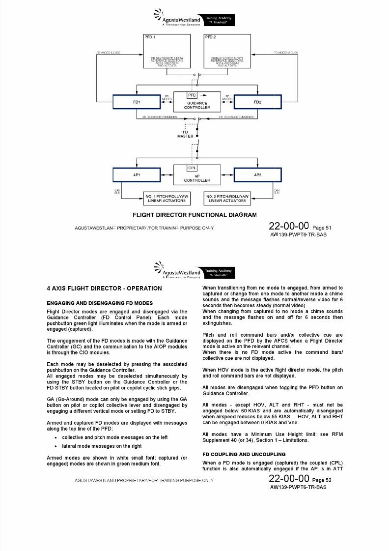
4-AXIS FLIGHT DIRECTOR – GENERAL
The dual Flight Directors (FD1 & FD2) provide lateral andvertical guidance commands that are normally coupled to the
Autopilots for automatic flight path control.
The 4-Axis (3-cue) FD provides lateral modes operating onthe roll axis and vertical modes operating on the pitch andcollective axes.
FD MASTER
At power up one of the two FD is automatically selected andconfigured as Master (priority). At every power up the FD
selected as Master is alternated: the selection is not visible tothe pilot.
PFD SELECTION (PILOT-IN-COMMAND)
Both FD1 and FD2 use the navigation source and dataf t d th l t d PFD
7/22/2019 Aw139 Pwpt6 Tr Bas Lowres
http://slidepdf.com/reader/full/aw139-pwpt6-tr-bas-lowres 146/1016
AGUSTAWESTLAND PROPRIETARY/FOR TRAINING PURPOSE ONLY 22-00-00 Page 50 AW139-PWPT6-TR-BAS
The 4-Axis Enhanced Flight Director provides all the functionsof the 4-Axis Basic Flight Director plus the AutoHover/Velocity Hold mode (HOV).References:
4-Axis Basic FD: RFM Supplement 40
4-Axis Enhanced FD: RFM Supplement 34
The 4-Axis Enhanced FD requires the following optional
equipment to be installed in place or in addition to the BasicFD: AHRS LCR-93 (in place of LCR-92) to provide AFCS
with hybrid Along-Heading and Across-Headingvelocities and accelerations (in addition to LCR-92data)
5-way cyclic BEEP TRIM switches (in place of 4-wayswitches)
reference presented on the selected PFD.PFD selection (which typically matches the “Pilot Flying” or
“Pilot in Command” determination) is controlled by the PFDpushbutton on the Guidance Controller.The selected PFD is indicated by the PFD couple arrow in thecenter of the top line of both PFD’s and by either the LH or theRH arrow-shaped LED annunciator aside the PFD pushbuttonon the Guidance Controller.
Whenever the PFD pushbutton is pressed to toggle LH/RHPFD selection all FD modes are disengaged (STBYilluminates on the Guidance Controller).
FD modes remain engaged in case the selected PFD fails: thepaired MFD reverting in Composite format keeps operating asthe selected PFD.
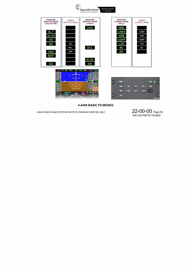
7/22/2019 Aw139 Pwpt6 Tr Bas Lowres
http://slidepdf.com/reader/full/aw139-pwpt6-tr-bas-lowres 147/1016
AG
USTAWESTLAN
PROPRIETAR
FLIG
/FOR TRAININ
HT DIRECT
PURPOSE ON
OR FUNCTI
Y
ONAL DIA
2 A
RAM
2-00-0139-PWPT6
Page 51
TR-BAS

7/22/2019 Aw139 Pwpt6 Tr Bas Lowres
http://slidepdf.com/reader/full/aw139-pwpt6-tr-bas-lowres 148/1016
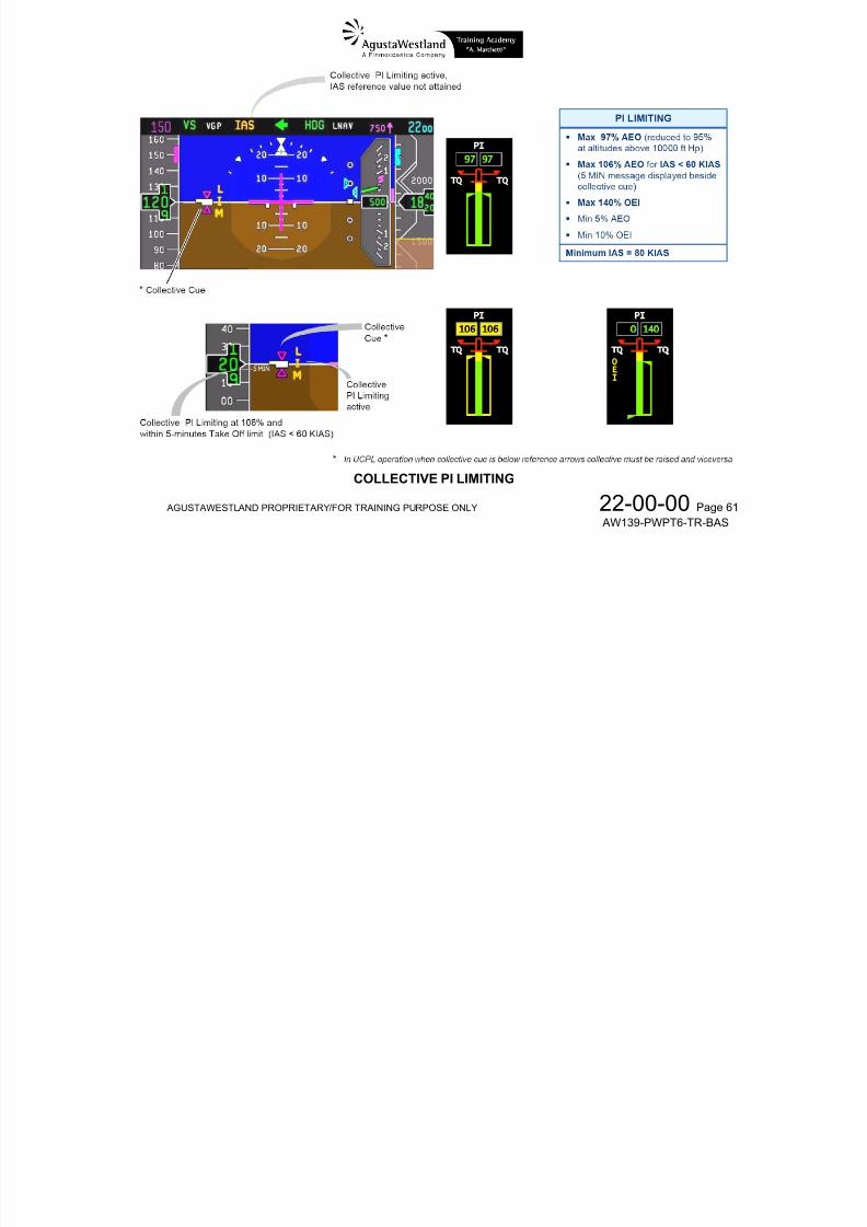
7/22/2019 Aw139 Pwpt6 Tr Bas Lowres
http://slidepdf.com/reader/full/aw139-pwpt6-tr-bas-lowres 149/1016
1
LIGHT DIR
. COLLECTI
(In view onThe collecthe require
. COLLECTI
ECTOR IND
E REFEREN
ly if a FD Collive referenced position of t
E CUE(In view onl
ICATORS
E MARKERS
ctive mode ismarkers (fixede collective le
if a FD Colle
engaged)) are set as ter to fulfil the
tive mode is
o hollow magFD collective
ngaged)
enta trianglesommand
pointing towar ds each other: they represe t

7/22/2019 Aw139 Pwpt6 Tr Bas Lowres
http://slidepdf.com/reader/full/aw139-pwpt6-tr-bas-lowres 150/1016
AG
. ENGAGEDShows wh
Green …
Amber …
. ARMED VEShows wh
. ENGAGEDShows wh
Green …
Amber …
USTAWESTLAN
(In view onlThe collectiIf collective
VERTICAL Ct collective m
……… Fligh
……... Collfunct
RTICAL MODt vertical mod
VERTICAL PIt pitch mode i
……… Fligh
……... Both
PROPRIETAR
if a FD Collee cue represeue is shown b
LLECTIVE Mde is engage
t Director is o
ctive trim action
Annunciator e(s) is(are) ar
CH MODE As engaged (ca
t Director is o
linear actuato
/FOR TRAININ
tive mode isnts the currentelow the refer
DE Annunci (captured)
erating norma
ator is failed
(white)ed (collective
nunciatorptured)
erating norma
s are failed or
PURPOSE ON
ngaged)position of thnce markers,
tor
lly
or collective
and/or pitch)
lly
vertical pitch
Y
collective levthe collective l
itch mode (ie
ode (ie IAS) i
2 A
r relative to reever is to be p
ALT) is affec
s affected by t
2-00-0139-PWPT6
ference markulled up, and
ed by the FD
e FD torque li
Page 54
TR-BAS
rs.iceversa.
torque limitin
miting functio
g
6. ENGAGED LATERAL MODE AnnunciatorShows what roll mode is engaged (captured)
Green …………… Flight Director is operating normally
Amber …………... Both linear actuators are failed
7. ARMED LATERAL MODE Annunciator (white)Shows what lateral mode is armed (roll)
Green …………… Flight Director is operating normally
A b B th li t t f il d
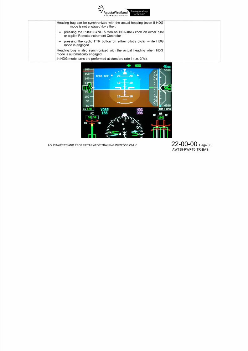
7/22/2019 Aw139 Pwpt6 Tr Bas Lowres
http://slidepdf.com/reader/full/aw139-pwpt6-tr-bas-lowres 151/1016
AGUSTAWESTLAND PROPRIETARY/FOR TRAINING PURPOSE ONLY 22-00-00 Page 55 AW139-PWPT6-TR-BAS
Amber …………... Both linear actuators are failed
8. FLIGHT DIRECTOR SOURCE SELECT ARROW AND STATUSThe source select arrow points towards the PFD that is supplying navigation and mode select data to both flight directors.
Green …………… Associated Flight Director is valid
Amber …………... Associated Flight Director is invalid
FD FAIL flag …… Both Flight Directors invalid (replaces the arrow annunciator)
9. FD COMMAND BARSShow the amount of roll (Lateral command bar) or pitch (Vertical command bar) guidance command from the Flight Director.
Either command bar is in view only if a relevant channel mode (roll or pitch) is engaged and is read withrespect to the ADI aircraft symbol.When a FD mode is engaged, and remains uncoupled from the AP, it permits the pilot to manually fly theaircraft using the directional cues presented by the command bars.
To follow the command bars, the pilot manually flies the aircraft to where the command bars intersect onthe ADI.In the example aside, the aircraft is below and to the left of the desired course and altitude. The pilotshould execute a climbing, right-hand turn to place the aircraft on course and at the designated altitude.
ARMEDVERTICALMODE
ENGAGEDVERTICAL MODE(PITCH)
PILOT-IN-COMMAND
ANNUNCIATORFD F IL
FLIGHTDIRECTOR
FAILED
ENGAGEDVERTICAL MODE(COLLECTIVE)
ENGAGEDLATERAL MODE(ROLL)
ARMEDLATERALMODE
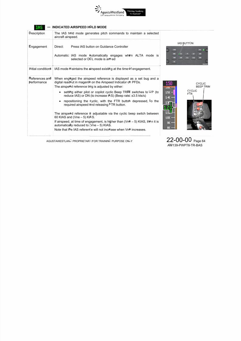
7/22/2019 Aw139 Pwpt6 Tr Bas Lowres
http://slidepdf.com/reader/full/aw139-pwpt6-tr-bas-lowres 152/1016
AGUSTAWESTLAND PROPRIETARY/FOR TRAINING PURPOSE ONLY 22-00-00 Page 56 AW139-PWPT6-TR-BAS
FLIGHT DIRECTOR
LATERALCOMMAND BAR
FLIGHT DIRECTORVERTICAL (PITCH)
COMMAND BAR
FLIGHT DIRECTORVERTICAL (CLTV)COMMAND BAR
(Collective Cue)
UCPL
CLTV
S S
FD UNCOUPLEDOPERATION
COLLECTIVEUNCOUPLED
NON-STANDARDMODE
ANNUNCIATOR
SAS MODE
FD INDICATIONS
VERTICAL MODES(PITCH)
FLIGHT DIRECTORSTAND-BY
VERTICAL MODES(COLLECTIVE)
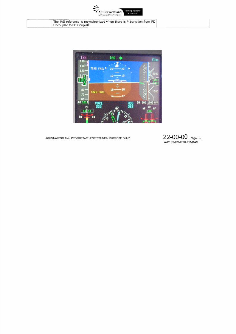
7/22/2019 Aw139 Pwpt6 Tr Bas Lowres
http://slidepdf.com/reader/full/aw139-pwpt6-tr-bas-lowres 153/1016
AGUSTAWESTLAND PROPRIETARY/FOR TRAINING PURPOSE ONLY 22-00-00 Page 57 AW139-PWPT6-TR-BAS
LATERAL MODES(ROLL)
FLIGHT DIRECTORCOUPLED/DECOUPLED
PFD SELECTOR(PILOT-IN-COMMAND)
APPROACHMODES
HOVER MODE(4-Axis Enhanced only)
4- AXIS BASIC FLIGHT DIRECTOR MODE SELECTION
FLIGHT DIRECTOR MODES
Mode Function Control AxisPFD caption
ARM CAPTURE
HDG Heading select Roll and Yaw N/A HDG
ALT Altitude Hold Collective N/A LT
IAS Indicated AirspeedHold Pitch N/A I S
Mode Function Control AxisPFD caption
ARM CAPTURE
DCL ILS DecelerationVGP Deceleration Pitch DCL DCL
BC Back Course Approach Roll BC BC
ALTA Altitude Acquire Collective N/A LT
VS Vertical Speed Collective N/A VS
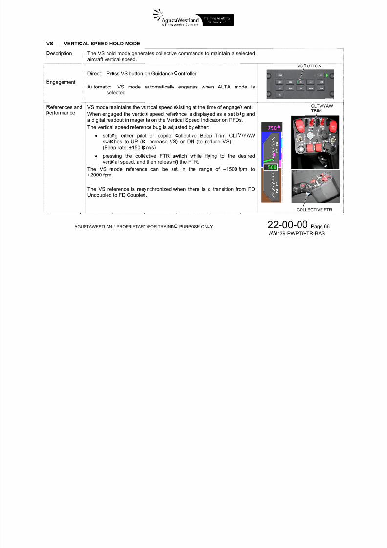
7/22/2019 Aw139 Pwpt6 Tr Bas Lowres
http://slidepdf.com/reader/full/aw139-pwpt6-tr-bas-lowres 154/1016
AGUSTAWESTLAND PROPRIETARY/FOR TRAINING PURPOSE ONLY 22-00-00 Page 58 AW139-PWPT6-TR-BAS
NAV Lateral navigation Roll
LNAV
VOR
LOC
LN V
VOR
LOC
APP
Lateral Approach Roll for VORor LOC
VAPP
LOC
V PP
LOC
Vertical ApproachCollective forGlide Slope
or VGP
GS
VGP
GS
VGP
PRV
Preselect VOR-ILSapproach while in
LNAVor Preselect VGP
N/A
VAPP
LOC
GS
VGP
N/A
VS Hold Collective N/A VS
GA Go-Around
Pitch for ASfunction/
Collective forVS function
N/A G
VGP Vertical Glide Path Collective VGP VGP
RHT Radar Height Hold Collective N/A RHT
HOV * Hover / VelocityHold Pitch / Roll N/A HOV
OS ** Over Station mode Roll N/A OS
ALVL ** Auto-Level mode Pitch /Collective N/A LVL
SBYClear all FD
modes N/A N/A N/A
* Only for 4-axis Enhanced FD
** Provided automatically
ENGAGEDLATERAL MODE
( ROLL )
HDG
LN V
VOR
V PP
LOC
BC
ARMEDLATERAL MODE
HDG
LN V
VOR
V PP
LOC
BC
ENGAGEDVERTICAL MODE
( PITCH )
I S
DCL
ARMEDVERTICAL MODE
HDG
DCL
VOR
V PP
ENGAGEDVERTICAL MODE( COLLECTIVE )
LT
LT
VS
GS GS
DCL
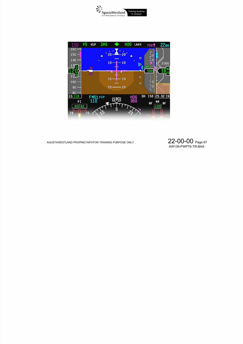
7/22/2019 Aw139 Pwpt6 Tr Bas Lowres
http://slidepdf.com/reader/full/aw139-pwpt6-tr-bas-lowres 155/1016
AGUSTAWESTLAND PROPRIETARY/FOR TRAINING PURPOSE ONLY 22-00-00 Page 59 AW139-PWPT6-TR-BAS
BC
OS
BC
OS
DCL
VGP
RHT
LVL
G
DCL
VGP
OS
OS
OS
4-AXIS BASIC FD MODES
COLLECTIVE PI LIMITING FUNCTION
During collective coupled operation the collective movement islimited by the following Power Index (PI) values:
Maximum 97% AEO (reduced to 95% at altitudes above10000 ft Hp)
Maximum 106% AEO for airspeed less than 60 KIAS(5 MIN message displayed beside collective cue)
Maximum 140% OEI
CAUTIONIf PI limiting is active with ALT or RHT engagedand the reference barometric altitude or radio
height cannot be maintained, the aural warning“ALTITUDE – ALTITUDE” will warn the pilotwhen the maximum allowed deviation from thereference setting has been exceeded.
When flying at high altitude (above 15000 ft), selecting theLD SHARE switch on MISC panel to TORQUE improves the
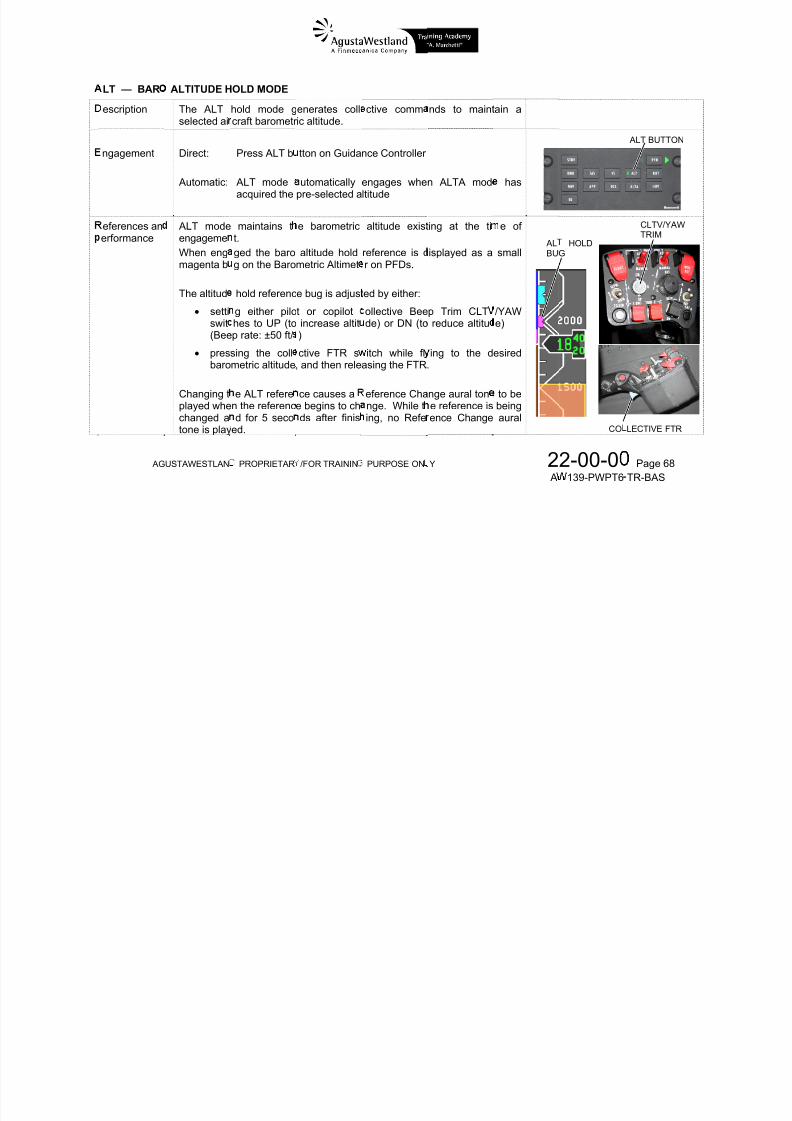
7/22/2019 Aw139 Pwpt6 Tr Bas Lowres
http://slidepdf.com/reader/full/aw139-pwpt6-tr-bas-lowres 156/1016
AGUSTAWESTLAND PROPRIETARY/FOR TRAINING PURPOSE ONLY 22-00-00 Page 60 AW139-PWPT6-TR-BAS
Minimum 5% AEO
Minimum 10% OEI
When PI limiting function is active and is limiting maximumcollective movement, an amber LIM caption is displayedbeside the collective cue.
If PI limiting is active with IAS engaged and the requiredreference for VS, ALTA, RHT, GA, or ALT cannot be achievedthen the airspeed will automatically reduce as necessary toachieve the collective mode reference.
If the collective mode reference cannot be maintained whenthe airspeed has reduced to a minimum of 80 KIAS, thisairspeed will be maintained (IAS caption is displayed in green)
and the collective mode reference will be reduced (thecollective mode caption is displayed in amber).
helicopter manoeuvering during automatic turns.
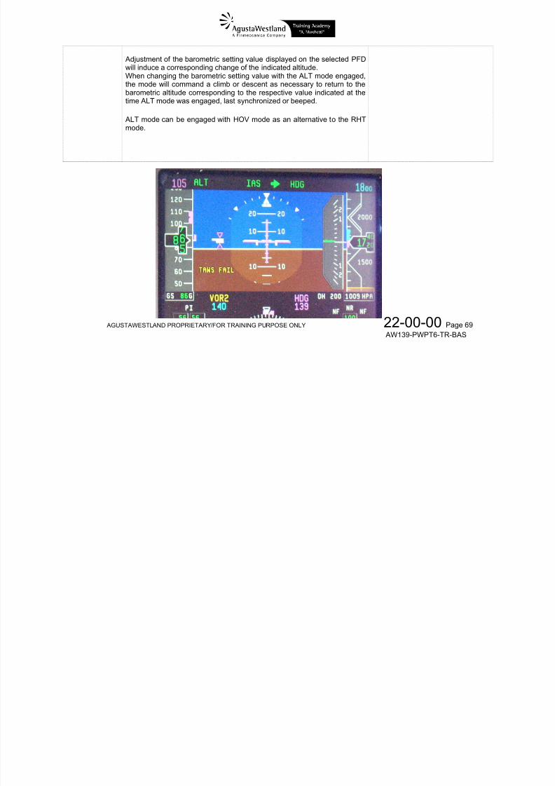
7/22/2019 Aw139 Pwpt6 Tr Bas Lowres
http://slidepdf.com/reader/full/aw139-pwpt6-tr-bas-lowres 157/1016
AGUSTAWESTLAND PROPRIETARY/FOR TRAINING PURPOSE ONLY 22-00-00 Page 61 AW139-PWPT6-TR-BAS
COLLECTIVE PI LIMITING
D MODES
he following d
—
escription
escriptions as
EADING HO
The HDGhold the Sassociated
Aircraft axiThe HDGh
ume the mod
D MODE
ode provides
elected Headi digital readous control is peelect mode is
i
s are coupled
the capabilityg referenceon the HSI.
formed via rollsupported wit
, unless state
to steer the aiisplayed as t
attitude.h turn coordin
otherwise.
rcraft to captue Heading Bu
tion functiona
e andg and
lity on
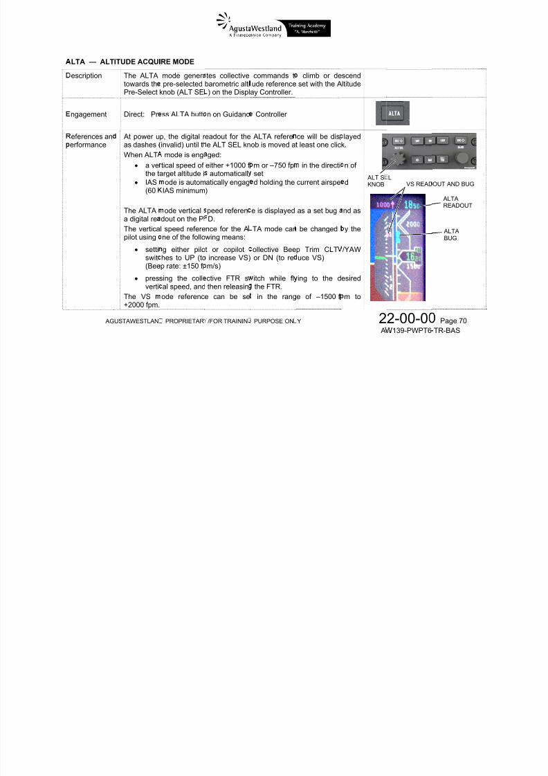
7/22/2019 Aw139 Pwpt6 Tr Bas Lowres
http://slidepdf.com/reader/full/aw139-pwpt6-tr-bas-lowres 158/1016
AG
ngagement
eferences anerformance
USTAWESTLAN
the yaw ax
Direct: Automatic:
When engare shown
The SelectHeading bby either:
rotatiInstru
settin
(Bee Note: O
pi
PROPRIETAR
is.
Press HDG bHDG mode amode is sele
ged Headingin magenta.
ed Heading reg can be set
g the HEADment Controll
either pilot
rate: ±3°/s fo
nly one Seleclot and copilot
/FOR TRAININ
utton on Guidutomatically eted (and arm
Bug and Sele
erence is thend adjusted (
ING knob or
r copilot cycl
first 3 second
ted Heading iare always en
PURPOSE ON
nce Controllengages whend): VOR, VA
ted Heading r
Heading Bugven if HDG m
either pilot
ic Beep TRIM
s and then ±1
available onabled to chan
Y
any of the follP, LOC, BC,
eadout on bot
n the HSI.ode is not en
or copilot R
switches to
°/s)
the helicopter e it.
2 A
owingNAV
HSIs
aged)
emote
or R
; both
HE
HDG
2-00-0139-PWPT6
ADING KNOB
CYCLICBEEP TRIM
CYCLIC FTR
UTTON
Page 62
TR-BAS
Heading bug can be synchronized with the actual heading (even if HDGmode is not engaged) by either:
pressing the PUSH SYNC button on HEADING knob on either pilotor copilot Remote Instrument Controller
pressing the cyclic FTR button on either pilot’s cyclic while HDGmode is engaged
Heading bug is also synchronized with the actual heading when HDGmode is automatically engaged.In HDG mode turns are performed at standard rate 1 (i.e. 3°/s).
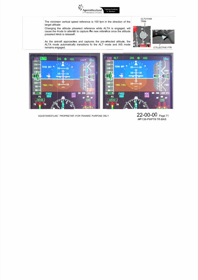
7/22/2019 Aw139 Pwpt6 Tr Bas Lowres
http://slidepdf.com/reader/full/aw139-pwpt6-tr-bas-lowres 159/1016
AGUSTAWESTLAND PROPRIETARY/FOR TRAINING PURPOSE ONLY 22-00-00 Page 63 AW139-PWPT6-TR-BAS
escription
ngagement
INDICATED
The IAS h
aircraft airs Direct:
Automatic:
AIRSPEED H
ld mode gen
peed.
Press IAS but
IAS modeselected or D
LD MODE
erates pitch c
ton on Guidan
utomaticallyL mode is ar
ommands to
ce Controller
engages whed
maintain a se
n ALTA mo
lected
de is
IAS BUTT N
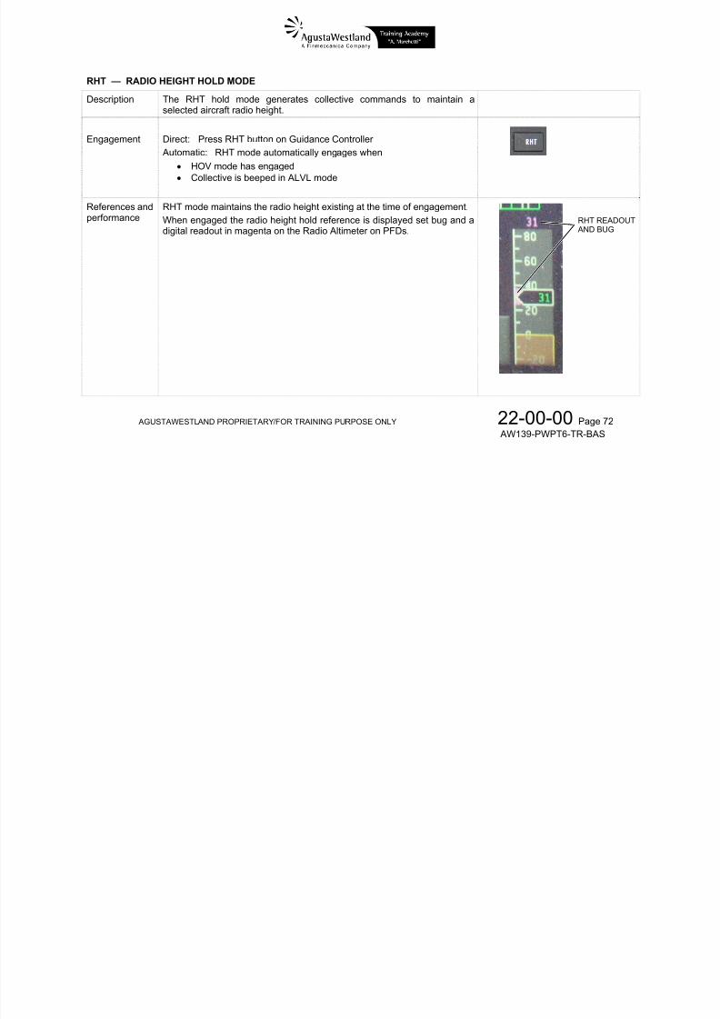
7/22/2019 Aw139 Pwpt6 Tr Bas Lowres
http://slidepdf.com/reader/full/aw139-pwpt6-tr-bas-lowres 160/1016
I
AG
itial condition
eferences anerformance
USTAWESTLAN
IAS mode
When engdigital readThe airspe
settiredu
reporequ
The airspe60 KIAS an
If airspeed,automaticalNote that t
PROPRIETAR
aintains the a
ged the airsput in magentd reference b
g either pilotce IAS) or DN
sitioning theired airspeed
d reference id (Vne – 5) KI
at time of engly reduced toe IAS referen
/FOR TRAININ
irspeed existi
eed reference on the Airspeg is adjusted
or copilot cyc(to increase I
yclic, with thnd releasing
adjustable vS.
agement, is hiVne – 5) KIASe will not incr
PURPOSE ON
g at the time
is displayeded Indicator oby either:
lic Beep TRIS) (Beep rate
e FTR buttoTR button.
ia the cyclic b
her than (Vn.ase when Vn
Y
f engagement
as a set bugPFDs.
switches to: ±3.5 kts/s)
depressed,
eep switch be
– 5) KIAS, th
increases.
2 A
.
and a
P (to
o the
tween
n it is
2-00-0139-PWPT6
CF
Page 64
TR-BAS
CYCLICBEEP TRIM
CLICR
The IAS reUncoupled
ference is resto FD Couple
ynchronized.
hen there is transition fro m FD

7/22/2019 Aw139 Pwpt6 Tr Bas Lowres
http://slidepdf.com/reader/full/aw139-pwpt6-tr-bas-lowres 161/1016
AG
USTAWESTLAN
PROPRIETAR
/FOR TRAININ
PURPOSE ON
Y 2
A2-00-0
139-PWPT6 Page 65
TR-BAS
S — VERTI
escription
ngagement
AL SPEED H
The VS hol
aircraft vert Direct: Pr
Automatic:sel
OLD MODE
d mode gener
ical speed.
ss VS button
VS modeected
ates collective
on Guidance
automatically
commands to
ontroller
engages wh
maintain a se
n ALTA mo
lected
de is
VS
UTTON
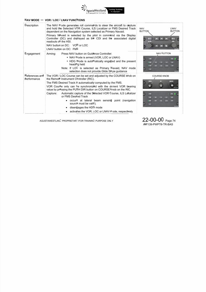
7/22/2019 Aw139 Pwpt6 Tr Bas Lowres
http://slidepdf.com/reader/full/aw139-pwpt6-tr-bas-lowres 162/1016
AG
eferences anerformance
USTAWESTLAN
VS modeWhen enga digital reThe vertica
settiswit
(Bee pres
vertiThe VS+2000 fpm. The VS reUncoupled
PROPRIETAR
aintains the vged the verticdout in magel speed refere
g either pilohes to UP (t
p rate: ±150 f sing the collal speed, andode referenc
erence is resto FD Couple
/FOR TRAININ
rtical speed el speed refer
ta on the Vertice bug is adju
t or copilotincrease VS
m/s)ctive FTR s then releasine can be se
nchronized.
PURPOSE ON
isting at the tince is displa
cal Speed Indisted by either:
ollective Bee or DN (to re
itch while fl the FTR.
in the rang
hen there is
Y
me of engageed as a set bcator on PFDs
p Trim CLTduce VS)
ing to the d
e of –1500 f
transition fro
2 A
ent.g and.
/YAW
esired
m to
m FD
2-00-0139-PWPT6
COL
Page 66
TR-BAS
CLTV/YAWTRIM
LECTIVE FTR
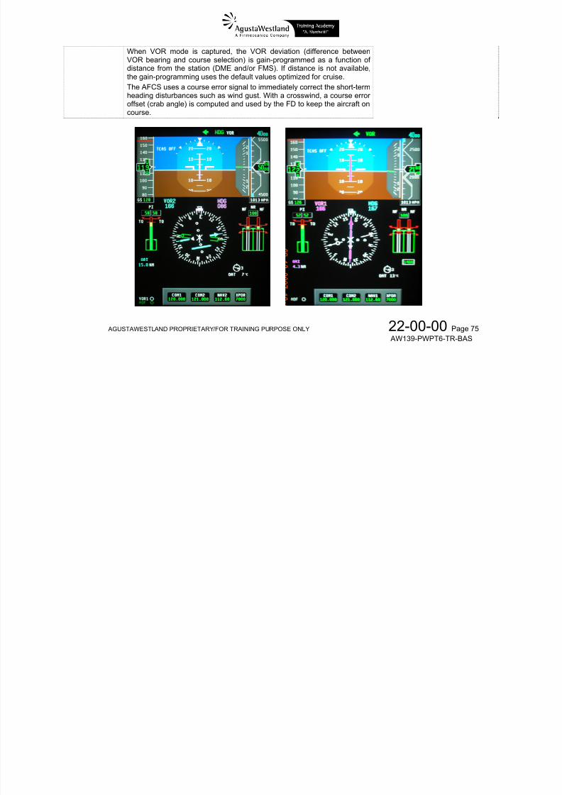
7/22/2019 Aw139 Pwpt6 Tr Bas Lowres
http://slidepdf.com/reader/full/aw139-pwpt6-tr-bas-lowres 163/1016
AGUSTAWESTLAND PROPRIETARY/FOR TRAINING PURPOSE ONLY 22-00-00 Page 67 AW139-PWPT6-TR-BAS
LT — BAR
escription
ngagement
ALTITUDE H
The ALTselected ai
Direct:
Automatic:
OLD MODE
hold mode gcraft barometr
Press ALT b
ALT modeacquired the
enerates collic altitude.
tton on Guida
utomaticallypre-selected a
ctive comm
nce Controller
engages wheltitude
nds to maint
n ALTA mod
ain a
has
ALT BUTTON
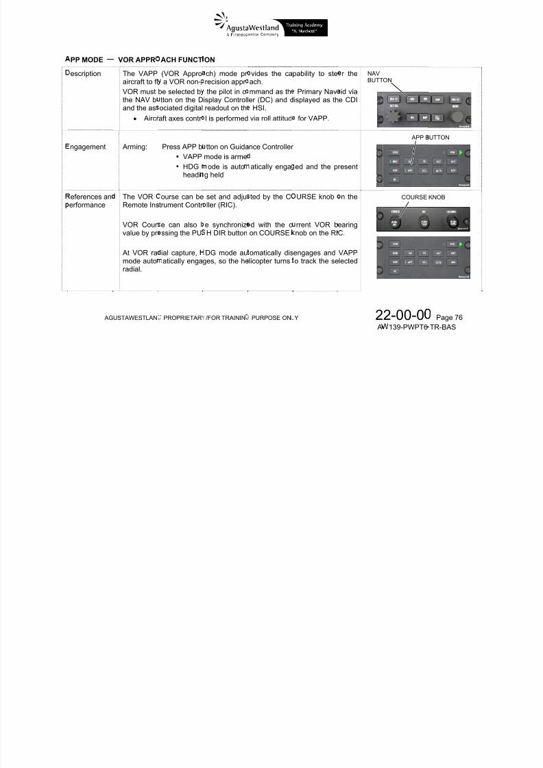
7/22/2019 Aw139 Pwpt6 Tr Bas Lowres
http://slidepdf.com/reader/full/aw139-pwpt6-tr-bas-lowres 164/1016
AG
eferences anerformance
USTAWESTLAN
ALT modeengagemeWhen engmagenta b The altitud
settiswit(Bee
presbaro
Changing tplayed whechanged atone is play
PROPRIETAR
maintains tt.ged the barog on the Baro
hold referenc
g either pilohes to UP (top rate: ±50 ft/
sing the collmetric altitude
e ALT referen the referencd for 5 seco
ed.
/FOR TRAININ
e barometric
altitude holdmetric Altimet
e bug is adjust
t or copilotincrease altit)
ctive FTR s, and then rele
ce causes ae begins to chds after finis
PURPOSE ON
altitude exist
reference is dr on PFDs.
ed by either:
ollective Beede) or DN (to
itch while flasing the FTR
eference Change. While ting, no Refe
Y
ing at the ti
isplayed as a
p Trim CLT reduce altitu
ing to the d.
nge aural tone reference isence Change
2 A
e of
small
/YAWe)
esired
to bebeingaural
ALBU
2-00-0139-PWPT6
HOLDG
CO
Page 68
TR-BAS
CLTV/YAWTRIM
LECTIVE FTR
Adjustment of the barometric setting value displayed on the selected PFDwill induce a corresponding change of the indicated altitude.When changing the barometric setting value with the ALT mode engaged,the mode will command a climb or descent as necessary to return to thebarometric altitude corresponding to the respective value indicated at thetime ALT mode was engaged, last synchronized or beeped.
ALT mode can be engaged with HOV mode as an alternative to the RHTmode.

7/22/2019 Aw139 Pwpt6 Tr Bas Lowres
http://slidepdf.com/reader/full/aw139-pwpt6-tr-bas-lowres 165/1016
AGUSTAWESTLAND PROPRIETARY/FOR TRAINING PURPOSE ONLY 22-00-00 Page 69 AW139-PWPT6-TR-BAS
LTA — ALT
escription
ngagement
eferences anerformance
ITUDE ACQUI
The ALTAtowards thPre-Select
Direct: Pr
At power uas dashes
RE MODE
mode gener pre-selected
knob (ALT SE
ss ALTA butt
p, the digital r invalid) until t
tes collectivebarometric alti) on the Displ
n on Guidanc
eadout for thee ALT SEL kn
commands tude referenceay Controller.
Controller
ALTA refereob is moved a
climb or de set with the A
ce will be dis
t least one clic
scendltitude
layed
k.

7/22/2019 Aw139 Pwpt6 Tr Bas Lowres
http://slidepdf.com/reader/full/aw139-pwpt6-tr-bas-lowres 166/1016
AG
e o a ce
USTAWESTLAN
as das esWhen ALT
a vethe t
IAS(60
The ALTAa digital reThe verticapilot using
settiswit(Bee
presverti
The VS+2000 fpm.
PROPRIETAR
va d) u t t mode is engtical speed of
arget altitude iode is autom
IAS minimum
ode verticaldout on the Pl speed referene of the follo
g either pilohes to UP (top rate: ±150 f
sing the collal speed, andode referenc
/FOR TRAININ
e Sged:
either +1000 f automaticall
atically engag)
peed referenD.nce for the Awing means:
t or copilotincrease VS)
m/s)
ctive FTR s then releasine can be se
PURPOSE ON
ob s oved a
m or –750 fp setd holding the
e is displayed
TA mode can
ollective Bee or DN (to re
itch while fl the FTR.
in the rang
Y
t east o e c c
in the directi
current airspe
as a set bug
be changed
p Trim CLTuce VS)
ing to the d
e of –1500 f
2 A
.
n of
d
nd as
y the
/YAW
esired
m to
ALT SKNOB
2-00-0139-PWPT6
VS READL
Page 70
TR-BAS
ALTABUG
ALTAREADOUT
OUT AND BUG
The minimtarget altituChanging t
cause thepreselect k
As the air ALTA modremains en
m vertical sp
dehe altitude pr
ode to attemob is release
raft approache automaticallgaged.
eed reference
eselect refere
t to capture t.
es and captuy transitions
is 100 fpm in
nce while AL
e new refere
res the pre-so the ALT m
the direction
TA is engage
ce once the a
lected altitudode and IAS
of the
d, will
ltitude
e, themode
CLTV/YAWTRIM
C LLECTIVE FTR

7/22/2019 Aw139 Pwpt6 Tr Bas Lowres
http://slidepdf.com/reader/full/aw139-pwpt6-tr-bas-lowres 167/1016
AG
USTAWESTLAN
PROPRIETAR
/FOR TRAININ
PURPOSE ON
Y 2
A2-00-0
139-PWPT6 Page 71
TR-BAS
RHT — RADIO HEIGHT HOLD MODE
Description The RHT hold mode generates collective commands to maintain aselected aircraft radio height.
Engagement Direct: Press RHT button on Guidance Controller Automatic: RHT mode automatically engages when
HOV mode has engaged Collective is beeped in ALVL mode
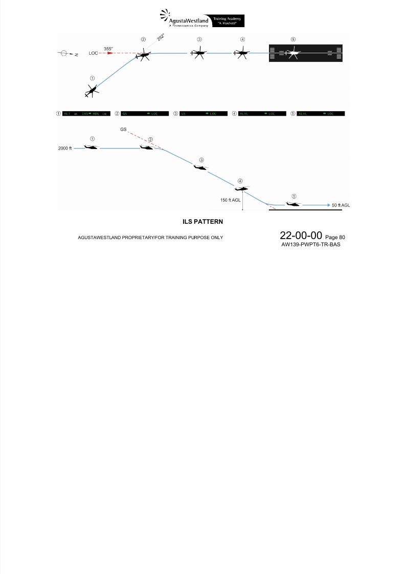
7/22/2019 Aw139 Pwpt6 Tr Bas Lowres
http://slidepdf.com/reader/full/aw139-pwpt6-tr-bas-lowres 168/1016
AGUSTAWESTLAND PROPRIETARY/FOR TRAINING PURPOSE ONLY 22-00-00 Page 72 AW139-PWPT6-TR-BAS
References andperformance
RHT mode maintains the radio height existing at the time of engagement.When engaged the radio height hold reference is displayed set bug and adigital readout in magenta on the Radio Altimeter on PFDs.
RHT READOUT AND BUG
The radio height hold reference bug is adjusted by either:
setting either pilot or copilot collective Beep Trim CLTV/YAWswitches to UP (to increase height) or DN (to reduce height)(Beep rate: ±50 ft/s)
pressing the collective FTR switch while flying to the desired radioheight, and then releasing the FTR.
CLTV/YAWTRIM
COLLECTIVE FTR
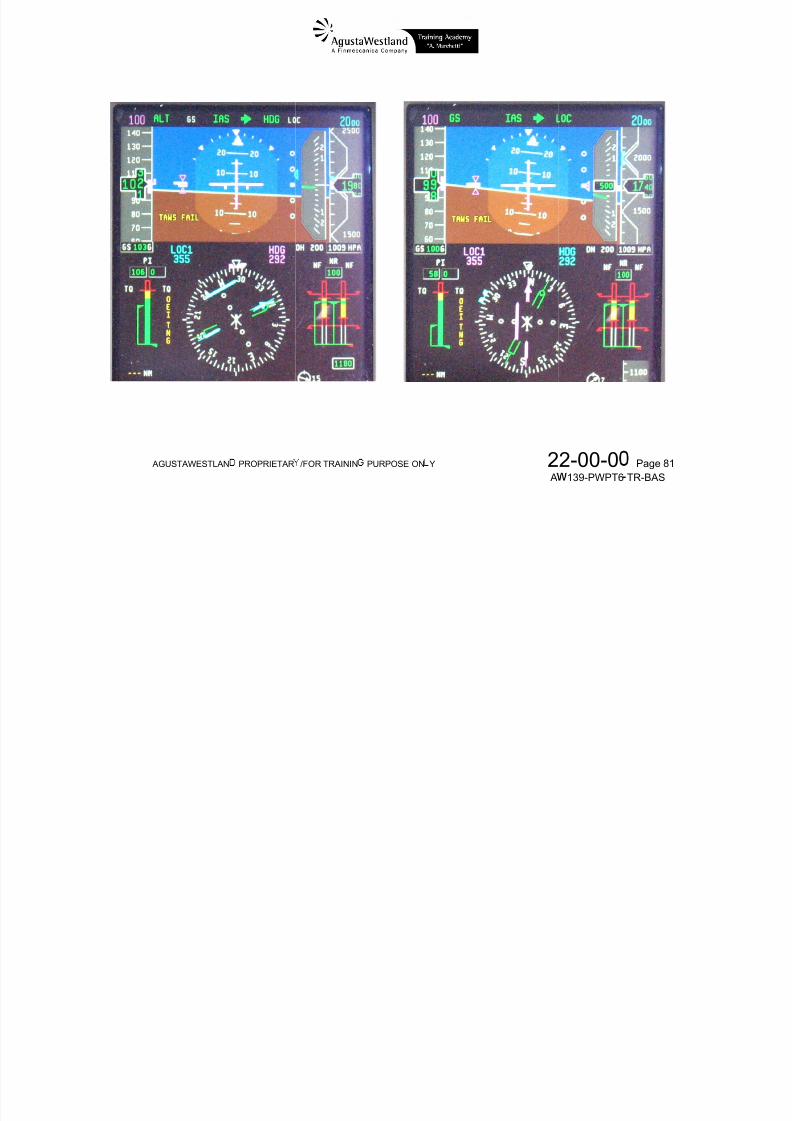
7/22/2019 Aw139 Pwpt6 Tr Bas Lowres
http://slidepdf.com/reader/full/aw139-pwpt6-tr-bas-lowres 169/1016
AGUSTAWESTLAND PROPRIETARY/FOR TRAINING PURPOSE ONLY 22-00-00 Page 73 AW139-PWPT6-TR-BAS
AV MODE
escription
ngagement
VOR / LOC
The NAVand hold thdependentPrimary NControllerreadouts oNAV buttonLNAV butto
Arming:
LNAV FUNC
ode generatee Selected V
on the Navigatvaid is selec
(DC) and dis the HSI.on DC: VO
n on DC: FM
Press NAV b
IONS
s roll commaR Course, IL
ion system selted by the played as th
or LOC
utton on Guid
ds to steer thS Localizer orected as Primilot in comm CDI and th
nce Controller
e aircraft to cFMS Desired
ary Navaid.nd via the D associated
.
ptureTrack
isplaydigital
NAVBUTT
ON
NAV
LNAVBUTTON
UTTON

7/22/2019 Aw139 Pwpt6 Tr Bas Lowres
http://slidepdf.com/reader/full/aw139-pwpt6-tr-bas-lowres 170/1016
AG
eferences anerformance
USTAWESTLAN
The VOR /the RemotThe FMS DVOR Cour value by pr Capture:
PROPRIETAR
NAV HDG
headiNote: If LO
selecti
LOC Course c Instrument Cesired Track ie only canssing the PU Automatic caor FMS Desi
occur
sourc disen activa
/FOR TRAININ
ode is armedode is auto
g heldis selected
on does not pr
an be set andntroller (RIC). automaticallye synchronizH DIR button
pture of the Sed Track
at lateral
must be valiages the HDes the VOR,
PURPOSE ON
(VOR, LOC oratically enga
as Primaryovide Glide Sl
adjusted by th computed byd with the con COURSElected VOR
beam sensin
),mode
OC or LNAV
Y
LNAV)ed and the p
avaid, NAVpe guidance
e COURSE k
the FMS.rrent VOR bnob on the RIourse, ILS Lo
point (navi
ode, respecti
2 A
resent
mode
ob on
earingC.alizer
gation
ely
2-00-0139-PWPT6
COURSE
Page 74
TR-BAS
KNOB
When VOR mode is captured, the VOR deviation (difference betweenVOR bearing and course selection) is gain-programmed as a function ofdistance from the station (DME and/or FMS). If distance is not available,the gain-programming uses the default values optimized for cruise.The AFCS uses a course error signal to immediately correct the short-termheading disturbances such as wind gust. With a crosswind, a course erroroffset (crab angle) is computed and used by the FD to keep the aircraft oncourse.

7/22/2019 Aw139 Pwpt6 Tr Bas Lowres
http://slidepdf.com/reader/full/aw139-pwpt6-tr-bas-lowres 171/1016
AGUSTAWESTLAND PROPRIETARY/FOR TRAINING PURPOSE ONLY 22-00-00 Page 75 AW139-PWPT6-TR-BAS
PP MODE
escription
VOR APPR
The VAPPaircraft to flVOR mustthe NAV band the as
Aircr
A i
ACH FUNCT
(VOR Appro a VOR non-
be selected btton on the Dociated digitalaft axes contr
P APP b
ON
ch) mode pr recision appr the pilot in cisplay Controllreadout on thl is performed
G id
vides the caach.mmand as ther (DC) and d HSI.via roll attitud
C ll
pability to ste
Primary Navisplayed as th
for VAPP.
r the
id viae CDI
NAVBUTT
ON
APP B
UTTON
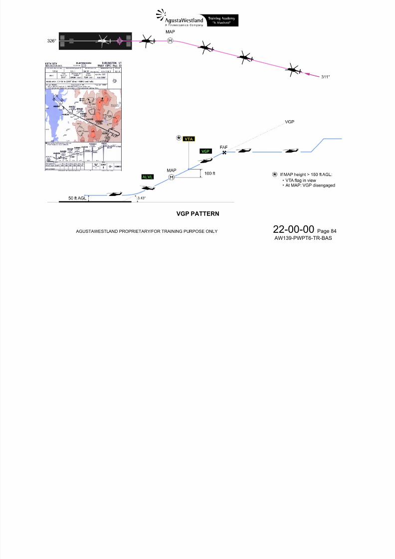
7/22/2019 Aw139 Pwpt6 Tr Bas Lowres
http://slidepdf.com/reader/full/aw139-pwpt6-tr-bas-lowres 172/1016
AG
ngagement
eferences anerformance
USTAWESTLAN
Arming:
The VORRemote Ins VOR Cour value by pr
At VOR ramode autoradial.
PROPRIETAR
Press APP b VAPP HDG
headi
ourse can betrument Contr
e can alsossing the PU
ial capture,atically enga
/FOR TRAININ
tton on Guidamode is armeode is auto
g held
set and adjuller (RIC).
e synchronizH DIR button
DG mode auges, so the he
PURPOSE ON
nce Controller atically enga
ted by the C
d with the con COURSE
omatically dislicopter turns
Y
ed and the p
URSE knob
rrent VOR bnob on the RI
engages ando track the se
2 A
resent
n the
earingC.
VAPPlected
2-00-0139-PWPT6
COURSE
Page 76
TR-BAS
KNOB

7/22/2019 Aw139 Pwpt6 Tr Bas Lowres
http://slidepdf.com/reader/full/aw139-pwpt6-tr-bas-lowres 173/1016
AGUSTAWESTLAND PROPRIETARY/FOR TRAINING PURPOSE ONLY 22-00-00 Page 77 AW139-PWPT6-TR-BAS
PP MODE
escription
ILS APPRO
The APPhold the IL LOC mustthe NAV band the as
Aircraft axe
roll
CH FUNCTI
ode providesLocalizer (L
e selected btton on the Dociated digital
s control is pe
ttitude for LO
N
the capabilityC) and Glide
the pilot in cisplay Controllreadout on th
formed via:
to steer the ailope (GS).
mmand as ther (DC) and d HSI.
rcraft to captu
Primary Navisplayed as th
e and
id viae CDI
NAVBUTT
ON

7/22/2019 Aw139 Pwpt6 Tr Bas Lowres
http://slidepdf.com/reader/full/aw139-pwpt6-tr-bas-lowres 174/1016
AG
ngagement
USTAWESTLAN
roll colle
Arming:
PROPRIETAR
ttitude for LOctive input for
Press APP b GS an HDG
headi
/FOR TRAININ
GS
tton on Guidad LOC modes
ode is autog held
PURPOSE ON
nce Controller are armedatically enga
Y
.
ed and the p
2 A
resent
2-00-0139-PWPT6
APP B
Page 78
TR-BAS
UTTON
eferences anerformance
The LOC iCOURSE k
At LOC ca
automaticallocalizer. At GS capand GS mto hold the
Upon comp
nbound (frontnob on the Re
pture, HDG
ly engages,
ture, any selde automatic
glide slope.
letion of ILS A
course can
mote Instrume
ode automati
so the helico
cted collectivlly engages,
pproach, ALV
only be setnt Controller (
cally disenga
pter turns to
mode autoo the helicop
mode is auto
nd adjustedIC).
es and LOC
track the se
atically disener adjusts coll
matically enga
y the
mode
lected
gagesective
ged.
COURSE KNOB

7/22/2019 Aw139 Pwpt6 Tr Bas Lowres
http://slidepdf.com/reader/full/aw139-pwpt6-tr-bas-lowres 175/1016
AG
USTAWESTLAN
PROPRIETAR
/FOR TRAININ
PURPOSE ON
Y 2
A2-00-0
139-PWPT6Page 79
TR-BAS

7/22/2019 Aw139 Pwpt6 Tr Bas Lowres
http://slidepdf.com/reader/full/aw139-pwpt6-tr-bas-lowres 176/1016
AGUSTAWESTLAND PROPRIETARY/FOR TRAINING PURPOSE ONLY 22-00-00 Page 80 AW139-PWPT6-TR-BAS
ILS PATTERN

7/22/2019 Aw139 Pwpt6 Tr Bas Lowres
http://slidepdf.com/reader/full/aw139-pwpt6-tr-bas-lowres 177/1016
AG
USTAWESTLAN
PROPRIETAR
/FOR TRAININ
PURPOSE ON
Y 2
A2-00-0
139-PWPT6 Page 81
TR-BAS
PP MODE
escription
VGP APPR
The APPapproachwith FMS sThe VerticDescent)in the data
Aircraft axe roll colle
Arming:
ACH FUNCTI
ode produchen using a n
elected as theal Glide Pathie the touchd
base at the cos control is pettitude for LNctive input for
Press APP b
ON (GPS/RN
s a non precon localizer bPrimary Navai (VGP) is awn point— wiresponding wformed via:V lateral steer GP
tton on Guidad d
V APPROAC
ision approacsed approac
d (LNAV buttochored at thth an angle eypoint.
ing
nce Controller
H)
h similar to a from the datn on DC).e BOD (Bottual to that sp
n ILSbase
m ofcified
APP B
LNAVBUTTON
UTTON

7/22/2019 Aw139 Pwpt6 Tr Bas Lowres
http://slidepdf.com/reader/full/aw139-pwpt6-tr-bas-lowres 178/1016
AG
ngagement
USTAWESTLAN
g
Conditions
FMSappr
FMS
Heli
Altit
If thhelic
No v Note: If
V
PROPRIETAR
VGP HDG
headifor arming VG
is selected aoach is select
is not in DR (
opter is within
de and angle
re is an altituopter must be
ertical direct-t
PP pushbuttP is not av
/FOR TRAININ
ode is armedode is auto
g heldmode:
Primary Navd as Arrival in
ead Reckoni
30 nm of dest
constraint valu
e constraint aat the FAF alti
the FAF has
n is pressedailable, the
PURPOSE ON
atically enga
aid and a pub the Active FP
g) mode
ination
es have not b
the FAF (Fintude
been execute
hen PrimaryGP UNAVAI
Y
ed and the p
lished non-LoL
en changed
l Approach Fi
Navaid is FM ABLE messa
2 A
resent
alizer
), the
S andge is
2-00-0139-PWPT6
Page 82
TR-BAS
displayed in the MCDU scratchpad.References andperformance
On the glide slope pointer a letter P is displayed to indicate VGP.When VGP mode is armed, both letter P and pointer appear on the lefthand side of vertical deviation scale.
When captured the symbol moves to the right hand side of the verticaldeviation scale.
When flying to the MAP (Missed Approach Point) or within 5 nm from theFAF, any selected collective mode automatically disengages and the VGPmode is automatically captured, so the helicopter adjusts collective to holdthe VGP.
Conditions for capturing VGP mode:

7/22/2019 Aw139 Pwpt6 Tr Bas Lowres
http://slidepdf.com/reader/full/aw139-pwpt6-tr-bas-lowres 179/1016
AGUSTAWESTLAND PROPRIETARY/FOR TRAINING PURPOSE ONLY 22-00-00 Page 83 AW139-PWPT6-TR-BAS
p g VGP mode must be armed
FMS active waypoint is the MAP or helicopter is within 5 nm of theFAF
If holding, helicopter must be established on the inbound course tothe FAF
Helicopter is able to capture the final approach slope
As the helicopter approaches the runway threshold, ALVL mode isautomatically engaged and collective is commanded for an asymptoticflare.If MAP height (in the Navigation Data Base) is greater than 150 ft AGL:
when helicopter is 100 ft above the MAP the VTA (Vertical Track Alert) flag appears on the ADI when helicopter is at the MAP the VGP mode disengages

7/22/2019 Aw139 Pwpt6 Tr Bas Lowres
http://slidepdf.com/reader/full/aw139-pwpt6-tr-bas-lowres 180/1016
AGUSTAWESTLAND PROPRIETARY/FOR TRAINING PURPOSE ONLY 22-00-00 Page 84 AW139-PWPT6-TR-BAS
VGP PATTERN
VGP CAPT
RED

7/22/2019 Aw139 Pwpt6 Tr Bas Lowres
http://slidepdf.com/reader/full/aw139-pwpt6-tr-bas-lowres 181/1016
AG
USTAWESTLAN
PROPRIETAR
/FOR TRAININ
PURPOSE ON
Y 2
A2-00-0
139-PWPT6 Page 85
TR-BAS
PP MODE
escription
ngagement
PREVIEW F
The Previewhile FD is
The PrevieDisplay C(LNAV butt
Arming:
NCTION
function is astill engaged i
function isntroller withn on DC).
Press APP b
GS an
way to preseln LNAV.
elected by pr FMS already
tton on Guida
d LOC modes
ct ILS or VO
ssing the PRselected as
nce Controller
are armed
Approach fun
pushbuttonhe Primary
.
ctions
n theavaid
PRVBUTTON
APP B
LNAVBUTTON
UTTON

7/22/2019 Aw139 Pwpt6 Tr Bas Lowres
http://slidepdf.com/reader/full/aw139-pwpt6-tr-bas-lowres 182/1016
AG
eferences anerformance
USTAWESTLAN
Selected Pcyan CDI a
Preview Von the RemPreview Vbearing valRIC.If the APPfunctions d
At the captand engag
PROPRIETAR
Helico
review Coursnd a small-fon
R/LOC Coursote InstrumenR Course c
ue by pressin
pushbutton ipending on th
ure of the LOs LOC-GS or
/FOR TRAININ
pter keeps flyi
is displayed digital readou
e can be set a Controller (RIn also be sy the PUSH DI
pressed thee NAV receiv
C or VAPP fuVAPP modes.
PURPOSE ON
g the LNAV l
on the HSIt.
nd adjusted bC).nchronized wiR button on C
FD arms LOr tuning (ILS
nctions the F
Y
g
s an addition
the COURS
th the currentURSE knob
and GS orr VOR).
disengages
2 A
l thin
knob
VORn the
VAPP
LNAV
2-00-0139-PWPT6
COURSE
Page 86
TR-BAS
KNOB

7/22/2019 Aw139 Pwpt6 Tr Bas Lowres
http://slidepdf.com/reader/full/aw139-pwpt6-tr-bas-lowres 183/1016
AGUSTAWESTLAND PROPRIETARY/FOR TRAINING PURPOSE ONLY 22-00-00 Page 87 AW139-PWPT6-TR-BAS
CL — ILS D
escription
CELERATIO
The DCL-Ideceleratioaircraft reaLOC mustthe NAV band the as
Aircraft axe roll colle pitch
Arming:
MODE
LS mode isfrom presen
hes 200 ft AGe selected btton on the Dociated digitals control is pettitude for LOctive input forattitude for aiPress DCL b
the same ast speed downL.the pilot in c
isplay Controllreadout on thformed via:
GSspeedtton on Guida
the APP m to approxima
mmand as ther (DC) and d HSI.
nce Controller
de plus auttely 80 KIAS
Primary Navisplayed as th
.
matics the
id viae CDI
NAVBUTT
ON
CL BUTTON

7/22/2019 Aw139 Pwpt6 Tr Bas Lowres
http://slidepdf.com/reader/full/aw139-pwpt6-tr-bas-lowres 184/1016
AG
ngagement
eferences anerformance
USTAWESTLAN
The LOC iCOURSE k
At LOC caautomaticallocalizer.
At GS capand GS mto hold the
After GS c
PROPRIETAR
GS-D HDG
headi IAS m
airspe
nbound (frontnob on the Re
pture, HDGly engages,
ture, any selde automatic
glide slope.pture and at
/FOR TRAININ
L and LOC mode is auto
g heldode is automd held
course canmote Instrume
ode automatiso the helico
cted collectivlly engages,
a computed
PURPOSE ON
odes are armeatically enga
atically engag
only be setnt Controller (
cally disengapter turns to
mode autoo the helicop
ondition for c
Y
ded and the p
ed and the p
nd adjustedIC).
es and LOCtrack the se
atically disener adjusts coll
rrect approac
2 A
resent
resent
y the
modelected
gagesective
h and
2-00-0139-PWPT6
COURSE
Page 88
TR-BAS
KNOB
deceleratioThe airspeset to 80 KIThese valuIAS modeUpon comp
the IAS modd reference b
AS.es can be adjutomatically eletion of ILS A
is disengage
ug moves to 8
sted using thngages replacpproach, ALV
d and the DCL0 KIAS and th
cyclic beep ting the DCL m mode is auto
mode engag
e digital refere
im at which tiode.matically enga
d.nce is
e the
ged.

7/22/2019 Aw139 Pwpt6 Tr Bas Lowres
http://slidepdf.com/reader/full/aw139-pwpt6-tr-bas-lowres 185/1016
AG
USTAWESTLAN
PROPRIETAR
/FOR TRAININ
PURPOSE ON
Y 2
A2-00-0
139-PWPT6 Page 89
TR-BAS

7/22/2019 Aw139 Pwpt6 Tr Bas Lowres
http://slidepdf.com/reader/full/aw139-pwpt6-tr-bas-lowres 186/1016

7/22/2019 Aw139 Pwpt6 Tr Bas Lowres
http://slidepdf.com/reader/full/aw139-pwpt6-tr-bas-lowres 187/1016
AGUSTAWESTLAND PROPRIETARY/FOR TRAINING PURPOSE ONLY 22-00-00 Page 91 AW139-PWPT6-TR-BAS
GO-AROUND MODE

7/22/2019 Aw139 Pwpt6 Tr Bas Lowres
http://slidepdf.com/reader/full/aw139-pwpt6-tr-bas-lowres 188/1016
AGUSTAWESTLAND PROPRIETARY/FOR TRAINING PURPOSE ONLY 22-00-00 Page 92 AW139-PWPT6-TR-BAS
OVER STATION MODE
HOV — HOVER/VELOCITY HOLD MODE
The HOV mode utilizes the blended AHRS-GPS groundvelocity information to provide commands that maintainlongitudinal and lateral aircraft ground velocities for hovering
and low speed flying.The HOV can be manually engaged by pressing the HOVpush button on the Guidance Controller or by pressing thebeep trim (Chinese-Hat fifth position) on the cyclic hand-grip.
At the engagement the HOV mode velocity references are setto zero. The engagement of HOV mode will automaticallyengage RHT mode if a valid radar altimeter signal is availableand within the threshold limits.The HOV mode velocity references may be changed by thepilot using any of the following means:
CAUTIONIn ALT mode the voice message “Altitude
Altitude” is triggered when altitude exceeds thereference altitude by ± 150 ft. Therefore, if ALTmode is engaged as an alternative to RHT at aheight below 300 ft, set DH at a value 10 ftbelow the reference height in order to have anadditional height deviation exceedances cue.
CAUTIONThe HOV mode maintains a groundspeedreference therefore pilot must ensure that

7/22/2019 Aw139 Pwpt6 Tr Bas Lowres
http://slidepdf.com/reader/full/aw139-pwpt6-tr-bas-lowres 189/1016
AGUSTAWESTLAND PROPRIETARY/FOR TRAINING PURPOSE ONLY 22-00-00 Page 93 AW139-PWPT6-TR-BAS
p g y g
pressing the cyclic FTR switch, flying to the desiredlateral and longitudinal velocities and then releasing thecyclic FTR switch
pressing the cyclic beep switch forward, aft, right, or left
to increase the velocity reference in the direction of theswitch press
pressing the cyclic beep fifth position switch to promptlyzero the velocity reference
The HOV mode velocity references are limited to a maximumof 60 knots forward and 40 knots left, right, and aft (while aft
the velocity reference is limited to 40 knots total vectoramplitude).
pcrosswind and rear wind speed limits are notexceeded. If wind limits are exceededdirectional control may not be maintained.
CAUTION
When HOV mode is engaged above 2000 ft AGL the ALT mode does not automaticallyengage. Therefore the pilot must controlcollective manually or engage ALT mode.
The hover symbology automatically appears on the PFD whenHOV mode is engaged. The display shows the aircraft velocityvector and the reference velocity symbol.

7/22/2019 Aw139 Pwpt6 Tr Bas Lowres
http://slidepdf.com/reader/full/aw139-pwpt6-tr-bas-lowres 190/1016
AGUSTAWESTLAND PROPRIETARY/FOR TRAINING PURPOSE ONLY 22-00-00 Page 94 AW139-PWPT6-TR-BAS
HOVER MODE

7/22/2019 Aw139 Pwpt6 Tr Bas Lowres
http://slidepdf.com/reader/full/aw139-pwpt6-tr-bas-lowres 191/1016
AGUSTAWESTLAND PROPRIETARY/FOR TRAINING PURPOSE ONLY 22-00-00 Page 95 AW139-PWPT6-TR-BAS
HOVER MODE OPERATION
FLIGHT DIRECTOR AURAL MESSAGES
VOICE ONLYMESSAGES DESCRIPTION
FD CHIME
Change state of any FD mode:
engaged to disengaged or viceversa arm to captured coupled to uncoupled or viceversa
BIP-BIP Change in altitude or radar height reference datum (target altitude or height)
Aircraft exceeded the altitude deviation, dependent on the selected mode, by:

7/22/2019 Aw139 Pwpt6 Tr Bas Lowres
http://slidepdf.com/reader/full/aw139-pwpt6-tr-bas-lowres 192/1016
AGUSTAWESTLAND PROPRIETARY/FOR TRAINING PURPOSE ONLY 22-00-00 Page 96 AW139-PWPT6-TR-BAS
ALTITUDE - ALTITUDE
± 150 ft from reference
Reference
Height (ft)
Deviation
(ft)30 1150 15
100 20150 25200 30250 40500 70
1000 1351500 2002000 260
LT
RHT
LIGHT DIR
PFD INDIC
ECTOR FAI
TION
reP
re
P
o
URES – P
FAI
places greenD that has fai
places FD arr
D displays w
attitude indic
D INDICATI
LURE DESC
rrow above atled Flight Dire
w above attit
en both FD h
tor during VG
ONS
IPTION
titude indicatotor
de indicator o
ve failed
P approach w
P
on SINGFAILU
both DUAL
FAIL
en VERT
OCEDURE
E FLIGHT DIRE
FLIGHT DIRE
ICAL TRACK
AME
ECTOR
CTOR
LERT
W139-RFM-4D

7/22/2019 Aw139 Pwpt6 Tr Bas Lowres
http://slidepdf.com/reader/full/aw139-pwpt6-tr-bas-lowres 193/1016
AG
OSS OF PFDNGAGED
USTAWESTLAN
oR(
WITH FD loce
rew
R
PROPRIETAR
attitude indicD ALT height
AP) and MAP
ss of PFD: thenfigure to Cogaged on the
places RAD Ahen both RAD
HT mode dise
/FOR TRAININ
tor during VG between Mis+100 ft
associated Mposite mode
same referen
LT height infor ALT 1 and 2 h
gages with a
PURPOSE ON
P approach wed Approach
D will automaaintaining th
es as the PF
mation on botave failed
dio chime
Y
enoint
VERTCAPT
ticallyFD
FAILUPFDDIRE
PFD DOUWITH
2 A
ICAL TRACKION
RE OF SELENIT WITH FLITOR ENGAG
LE RAD ALTRHT ENGAG
2-00-0139-PWPT6
E
LERT
TEDGHTED
AILURED
Page 97
TR-BAS
Supplement 34
Supplement 40
―
Section 3
ERGENCY ANMALFUNCTIONPROCEDURES
PFD INDIC
VEL
FAIL
TION
oR
R
btha
Tre
a
b
FAI
RAD ALT disD ALT 1 and
HT mode dise
low and to the valid velocitailable.
e velocity vecmoved and th
tomatically.
low and to th
LURE DESC
play when mis2 information
gages with a
left of the co data from bot
tor on the hove HOV mode
left of the co
IPTION
compare betw
dio chime
pass rose whh AHRS is not
r display isisengages
pass rose wh
P
een RADWITH
en VELO
en None
OCEDURE
LT MISCOMRHT ENGAG
CITY VECTO
AME
ARED
FAIL
E
W139-RFM-4D
Supplement 34
―
Section 3
ERGENCY ANMALFUNCTION
PROCEDURES

7/22/2019 Aw139 Pwpt6 Tr Bas Lowres
http://slidepdf.com/reader/full/aw139-pwpt6-tr-bas-lowres 194/1016
If
AG
VELTES
UIDANCE C
n case of guunctionality ofhanged or disay be diseng
USTAWESTLAN
v
NTROLLER
idance contropanel pushb
engaged usinged using the
PROPRIETAR
locity is report
AILURE
ller failure, r ttons (that isthe panel pu
cyclic FD ST
/FOR TRAININ
ed in test from
cognised asmodes cannohbuttons), thY button.
PURPOSE ON
p an AHRS sou
nont be
FD
Y
rce.
2 A
2-00-0139-PWPT6
Page 98
TR-BAS
FLIGHT DIRECTOR FAILURES – CAS MESSAGES
CAS CAPTION FAILURE DESCRIPTION PROCEDURE NAME AW139-RFM-4D
1(2) COLL FAIL
+ aural message
Collective axis of AP1(2) failNOTE: Collective FD mode annunciator amber (if
a coupled collective mode is active)
SINGLE COLLECTIVE AUTOPILOT FAILURE
Supplement 34S l 40
1-2 COLL FAIL
+ aural message
Collective axis of AP1(2) failure on both AP 1 and AP 2
NOTE: Collective FD mode annunciator amber (if
a coupled collective mode is active)
DUAL COLLECTIVE AUTOPILOT FAILURE
associated AHRS failure and subsequent loss of AHRS FAILURE WITH FD

7/22/2019 Aw139 Pwpt6 Tr Bas Lowres
http://slidepdf.com/reader/full/aw139-pwpt6-tr-bas-lowres 195/1016
AGUSTAWESTLAND PROPRIETARY/FOR TRAINING PURPOSE ONLY 22-00-00 Page 99 AW139-PWPT6-TR-BAS
Supplement 40
―
Section 3
EMERGENCY ANDMALFUNCTIONPROCEDURES
1(2) AHRS FAIL
AVIONIC FAULT
AFCS DEGRADED
1(2) AP FAIL
+
ATT
FAIL
HDG
FAIL
on PFD
+ aural message
q AP 1(2)
and loss of attitude, heading and slip skid data onLeft (Right) PFD
ENGAGED
CAS CAPTION FAILURE DESCRIPTION PROCEDURE NAME AW139-RFM-4D
ATT OFF
+ SAS message displayed on both PFD’s
Note
With ATT system not engaged the aircraft flies inSAS mode only
ATTITUDE SYSTEM OFF
Supplement 34
Supplement 40
―
Section 3
EMERGENCY ANDMALFUNCTIONPROCEDURES1(2) ADS FAIL
On-side ADS failure on the selected PFD.
Disengagement of FD vertical modes
(ALT, IAS, VS) + Audio Chime and loss of
Airspeed Altitude
ON SIDE ADS FAILURE ONSELECTED PFD WITH FDENGAGED

7/22/2019 Aw139 Pwpt6 Tr Bas Lowres
http://slidepdf.com/reader/full/aw139-pwpt6-tr-bas-lowres 196/1016
AGUSTAWESTLAND PROPRIETARY/FOR TRAINING PURPOSE ONLY 22-00-00 Page 100 AW139-PWPT6-TR-BAS
Vertical speed
Data on Left(Right) indicators
LIMITATIONSRefer to AW139-RFM-4D, Supplement 34 or Supplement 40, SECTION 1 for:
WEIGHT AND CENTRE OF GRAVITY LIMITATIONS FLIGHT DIRECTOR MODES LIMITATIONS FLIGHT DIRECTOR MODES ENGAGEMENT LIMITS AND MINIMUM USE HEIGHT (MUH)
REQUIRED EQUIPMENT VOR LIMITATIONS ILS APPROACH MODE LIMITATIONS VGP LIMITATIONS
CHAPTER23COMMUNICATIONS

7/22/2019 Aw139 Pwpt6 Tr Bas Lowres
http://slidepdf.com/reader/full/aw139-pwpt6-tr-bas-lowres 197/1016
AGUSTAWESTLAND PROPRIETARY/FOR TRAINING PURPOSE ONLY 23-00-00 Page 1 AW139-PWPT6-TR-BAS
COMMUNICATIONS
SECTION 00 – GENERAL

7/22/2019 Aw139 Pwpt6 Tr Bas Lowres
http://slidepdf.com/reader/full/aw139-pwpt6-tr-bas-lowres 198/1016
AGUSTAWESTLAND PROPRIETARY/FOR TRAINING PURPOSE ONLY 23-00-00 Page 2 AW139-PWPT6-TR-BAS
COMMUNICATIONS – GENERALThe communication system contains the equipment forcommunicating inside the helicopter, with other aircraft andwith ground stations.
The communication system consists of the following mainsub-systems:• the Modular Radio System• the Audio Integrating System
MODULAR RADIO SYSTEM – GENERALThe Mod lar Radio S stem incl des the Mod lar Radio
MODULAR RADIO SYSTEM – MAIN COMPONENTSThe MRC accommodates radio modules from the PRIMUSEPIC® system into one Line Replaceable Unit (LRU). TheMRC is usually installed in a dual system configuration withMRC 1 on the left side (copilot) and MRC 2 on the right side(pilot). The two MRC doesn’t however contain all the sameradio modules. Each radio module consists of circuit cards,backplane connectors and front mounting plate withconnectors. In addition, each radio module contains its ownpower supply and self-test circuitry that can be activated as aninitiated built-in test (IBIT).
Usually the MRC 1 contains the following modules:• Network Interface Module (NIM)
VHF NAV d l (VIDL d l VOR/ILS/D Li k

7/22/2019 Aw139 Pwpt6 Tr Bas Lowres
http://slidepdf.com/reader/full/aw139-pwpt6-tr-bas-lowres 199/1016
AGUSTAWESTLAND PROPRIETARY/FOR TRAINING PURPOSE ONLY 23-00-00 Page 3 AW139-PWPT6-TR-BAS
The Modular Radio System includes the Modular RadioCabinet (MRC), which is the core of the communication andnavigation system, with related controls, displays, andantennas. The MRC uses modules from the PRIMUS EPIC®system that supply Communication and Navigational data tothe aircrew. The MRC contains the standard navigation andcommunication systems, including VOR, ILS, DME, ADF andVHF communication and the transponder system.
• VHF-NAV module (VIDL module = VOR/ILS/Data Linkmodule) (VOR = Very high frequency Omni-directionalradio Range; ILS = Instrument Landing System)
Usually the MRC 2 contains the following modules:• Network Interface Module (NIM)• VHF-NAV module (VIDL module = VOR/ILS/Data Link
module)• DME (Distance Measuring Equipment) module• ADF (Automatic Direction Finder) module•
VHF-COMM module (VDL module = VHF Data Linkmodule)
• XPDR (Transponder) module
MODULAR RADIO CABINET (MRC)
The MRC consists of a cabinet that houses multiple linereplaceable modules providing aircraft radio functions.
NI-900 NIM MODULEThe NIM module consists of two sections:
• the NIC (Network Interface Controller) section thatcomprises the standard NIC circuit as used on all other
ASCB-D connected units• the central cabinet processing section (NIM CPU) which
uses an Intel 80486 processor, DEOS (synchronized to ASCB-D) and PRIMUS EPIC core software components
XS--856A XPDR Module
The XPDR contains a transceiver that gives air traffic controlradar beacon system (ATCRBS), Mode S and diversitytransponder capability

7/22/2019 Aw139 Pwpt6 Tr Bas Lowres
http://slidepdf.com/reader/full/aw139-pwpt6-tr-bas-lowres 200/1016
AGUSTAWESTLAND PROPRIETARY/FOR TRAINING PURPOSE ONLY 23-00-00 Page 4 AW139-PWPT6-TR-BAS
NV-75A VIDL MODULE
The VIDL gives VOR/ILS and data link functionality (futureimplementation). It contains a VOR/LOC receiver, GS (GlideSlope) receiver and a marker beacon (MKR BCN) receiver.
DF-855 ADF MODULE
The ADF contains an ADF receiver that enables en route andterminal navigational and area guidance.
DM--855 DME MODULEThe DME contains a DME receiver that enables en route andterminal navigational and area guidance.

7/22/2019 Aw139 Pwpt6 Tr Bas Lowres
http://slidepdf.com/reader/full/aw139-pwpt6-tr-bas-lowres 201/1016
AGUSTAWESTLAND PROPRIETARY/FOR TRAINING PURPOSE ONLY 23-00-00 Page 5 AW139-PWPT6-TR-BAS
MODULAR RADIO CABINET (MRC) – LOCATION OF MODULES

7/22/2019 Aw139 Pwpt6 Tr Bas Lowres
http://slidepdf.com/reader/full/aw139-pwpt6-tr-bas-lowres 202/1016
AGUSTAWESTLAND PROPRIETARY/FOR TRAINING PURPOSE ONLY 23-00-00 Page 6 AW139-PWPT6-TR-BAS
MRC 1 AND MRC 2 INSTALLATION

7/22/2019 Aw139 Pwpt6 Tr Bas Lowres
http://slidepdf.com/reader/full/aw139-pwpt6-tr-bas-lowres 203/1016
AGUSTAWESTLAND PROPRIETARY/FOR TRAINING PURPOSE ONLY 23-00-00 Page 7 AW139-PWPT6-TR-BAS
LOCATION OF ANTENNAS

7/22/2019 Aw139 Pwpt6 Tr Bas Lowres
http://slidepdf.com/reader/full/aw139-pwpt6-tr-bas-lowres 204/1016

7/22/2019 Aw139 Pwpt6 Tr Bas Lowres
http://slidepdf.com/reader/full/aw139-pwpt6-tr-bas-lowres 205/1016
VHF-COMM (VDL) MODULE
The VHF communications module gives two-way, air-to-air,and air-to-ground communication in the frequency range of118.000 MHz to 136.975 MHz with 8.33 kHz or 25 kHzchannel spacing, which is selectable through the MCDU.
The system has an automatic transmit time-out function toprevent blockage of a communication channel when a push-to-talk (PTT) switch is stuck closed.
The VDR supplies the following voice and data radiofunctions:
• 8.33 kHz channel ARINC 716 compatible analog voice
communications transceiver• 25 kHz channel ARINC 716 compatible analog voice
communications transceiver
installations on other aircrafts. The XPDR supports basicdownlink aircraft parameters. The NIM supplies barometricaltitude data from the Air Data System (ADS). Thetransponder is provided with an ARINC 429 backup bus incase of the NIM fails.
The flight ID information is given by the FMS or it can beentered by the pilot. The XPDR receives the ICAO addressprogrammed into the aircraft personality module (APM) andthe pilot enters the squawk code.
The transponder connects to the display system through the ASCB-D, following the same arrangement as the other radiosystems.
On the following schematics red, light green and yellow largerlines represent digital buses; light blue, green, brown (AWG

7/22/2019 Aw139 Pwpt6 Tr Bas Lowres
http://slidepdf.com/reader/full/aw139-pwpt6-tr-bas-lowres 206/1016
AGUSTAWESTLAND PROPRIETARY/FOR TRAINING PURPOSE ONLY 23-00-00 Page 10 AW139-PWPT6-TR-BAS
The VDR has its own power supply and can operateindependently from the NIM. In fact, when a NIM fails the
ARINC 429 bus maintains the control of the module. Ananalog audio backup control is available (headphones) byselecting the backup button on the audio panels. This functionbypasses the MIC bus in the NIM and audio panels.
XPDR MODULE
The XPDR module modes of operation are mode A, C and S.Mode S enables secondary surveillance by transmission of
aircraft identification information, altitude (barometric) andcoded message data to air traffic control (ATC) groundstations and Traffic Collision Avoidance System (TCAS)
p g g g (audio) and purple thinner lines represent analog signal lines.The pink line between the cabin audio control panel and thepilot audio control panel represent a direct connection of theunits.

7/22/2019 Aw139 Pwpt6 Tr Bas Lowres
http://slidepdf.com/reader/full/aw139-pwpt6-tr-bas-lowres 207/1016
AGUSTAWESTLAND PROPRIETARY/FOR TRAINING PURPOSE ONLY 23-00-00 Page 11 AW139-PWPT6-TR-BAS
MODULAR RADIO SYSTEM – GENERAL LAYOUT

7/22/2019 Aw139 Pwpt6 Tr Bas Lowres
http://slidepdf.com/reader/full/aw139-pwpt6-tr-bas-lowres 208/1016
AGUSTAWESTLAND PROPRIETARY/FOR TRAINING PURPOSE ONLY 23-00-00 Page 12 AW139-PWPT6-TR-BAS
MODULAR RADIO SYSTEM – NORMAL RADIO OPERATION

7/22/2019 Aw139 Pwpt6 Tr Bas Lowres
http://slidepdf.com/reader/full/aw139-pwpt6-tr-bas-lowres 209/1016
AGUSTAWESTLAND PROPRIETARY/FOR TRAINING PURPOSE ONLY 23-00-00 Page 13 AW139-PWPT6-TR-BAS
EXTERNAL INTERCOMMUNICATION JACK
BACKUP ICS MODE
Each audio panel has a backup mode that can be selectedwhen one of the audio panels fail. The backup mode permitsthe pilot headset to be connected directly to the on--side VHFCOMM or off-side audio panel ICS.
No power is required to the on-side audio panel. Switching thepilots MIC between the COM radio and the off-sidemaintenance port is performed by an external relay controlledby the PTT button.
The audio panel backup mode controls the ICS and COMaudio volume through the use of a single volume control knob.The control knob is located on the lower left corner of theaudio panel and labelled BKUP.
The ICS and COM audio volumes cannot be adjustedseparately.

7/22/2019 Aw139 Pwpt6 Tr Bas Lowres
http://slidepdf.com/reader/full/aw139-pwpt6-tr-bas-lowres 210/1016
AGUSTAWESTLAND PROPRIETARY/FOR TRAINING PURPOSE ONLY 23-00-00 Page 14 AW139-PWPT6-TR-BAS

7/22/2019 Aw139 Pwpt6 Tr Bas Lowres
http://slidepdf.com/reader/full/aw139-pwpt6-tr-bas-lowres 211/1016
AGUSTAWESTLAND PROPRIETARY/FOR TRAINING PURPOSE ONLY 23-00-00 Page 15 AW139-PWPT6-TR-BAS
MODULAR RADIO SYSTEM – BACKUP MODE

7/22/2019 Aw139 Pwpt6 Tr Bas Lowres
http://slidepdf.com/reader/full/aw139-pwpt6-tr-bas-lowres 212/1016
RADIO - CONTROLS AND INDICATORS
1. RADIO pushbutton
pressed …….. displays the RADIO 1/2 page
2. PREV pushbuttonpressed …….. allows to return to the previous page
3. LINE SELECT KEY
pressed …….. allows to operate the MCDU menu items
4. ALPHA keypad
pressed …….. allows to insert alphabetical characters in the scratchpad
5. NUMERIC keypad
pressed …….. allows to insert numerical characters in the scratchpad

7/22/2019 Aw139 Pwpt6 Tr Bas Lowres
http://slidepdf.com/reader/full/aw139-pwpt6-tr-bas-lowres 213/1016
AGUSTAWESTLAND PROPRIETARY/FOR TRAINING PURPOSE ONLY 23-00-00 Page 17 AW139-PWPT6-TR-BAS
pressed …….. allows to insert numerical characters in the scratchpad
SWAP FREQUENCIES The symbol indicates exchanges between the active and preset frequencies for the associated radiothat can be made. This effectively saves the currently active frequency in the preset memory andtunes the radio to the frequency previously stored as the preset.
PAGE INDICATOR When the icon is displayed, pushing the adjacent Line Select Key (LSK) changes the display to
another page. The page to be displayed is labelled explicitly or it is a detail page for the radio in theassociated field.
EXCLUSIVE SELECTION The icon is displayed next to a list of mutually exclusive options. Each time the adjacent LSK ispushed, the next item in the list is selected, wrapping around to the first when the last option isreached.
The selected value is displayed in green large font.
The unselected values are displayed in small white fonts.
IMMEDIATE FUNCTION The icon indicates the function identified in the field executed immediately after the associated LSKkey is pushed

7/22/2019 Aw139 Pwpt6 Tr Bas Lowres
http://slidepdf.com/reader/full/aw139-pwpt6-tr-bas-lowres 214/1016
AGUSTAWESTLAND PROPRIETARY/FOR TRAINING PURPOSE ONLY 23-00-00 Page 18 AW139-PWPT6-TR-BAS
key is pushed.
COPY VALUE The icon is used on the memory pages to indicate that the frequency highlighted by the cursor is
copied into the active frequency for the associated radio.
CURSOR The cursor box highlights the value in the active field.
TUNING CURL The icon indicates that the data value highlighted by the format cursor can be changed by turning the
MCDU tuning knob.

7/22/2019 Aw139 Pwpt6 Tr Bas Lowres
http://slidepdf.com/reader/full/aw139-pwpt6-tr-bas-lowres 215/1016
AGUSTAWESTLAND PROPRIETARY/FOR TRAINING PURPOSE ONLY 23-00-00 Page 19 AW139-PWPT6-TR-BAS
MULTIFUNCTION CONTROL DISPLAY UNIT (MCDU)

7/22/2019 Aw139 Pwpt6 Tr Bas Lowres
http://slidepdf.com/reader/full/aw139-pwpt6-tr-bas-lowres 216/1016
AGUSTAWESTLAND PROPRIETARY/FOR TRAINING PURPOSE ONLY 23-00-00 Page 20 AW139-PWPT6-TR-BAS
MCDU DISPLAY PROMPTS
Three types of radio frequencies can be displayed:• Active frequency is the one that the radio is currently set
to for receiving or transmitting• Standby frequency is the one waiting to be used next.
The Standby frequency can be changed using the tuningknobs or the scratchpad
• Memory frequency is the one with a list of frequenciesthat is stored for recall
Two swap functions are used. The first one uses the standbyfrequency. The second one uses the memory frequency.
•
With the cursor around the standby frequency and theswap icon displayed when the line select key is pushed,the standby and active frequencies are switched.
• With the cursor around the Memory frequency and thei di l d h th li l t k i h d

7/22/2019 Aw139 Pwpt6 Tr Bas Lowres
http://slidepdf.com/reader/full/aw139-pwpt6-tr-bas-lowres 217/1016
AGUSTAWESTLAND PROPRIETARY/FOR TRAINING PURPOSE ONLY 23-00-00 Page 21 AW139-PWPT6-TR-BAS
swap icon displayed when the line select key is pushed,the Memory and Active frequencies are switched.
To make the standby frequency active, push the 4L buttonnext to the active COM frequency. This swaps the Standbyand Active frequencies.
VHF COM and HF COM radio pages use Active, Standby,and Memory frequencies. They do not permit the use of thetuning knobs to change the Active frequency.

7/22/2019 Aw139 Pwpt6 Tr Bas Lowres
http://slidepdf.com/reader/full/aw139-pwpt6-tr-bas-lowres 218/1016
AGUSTAWESTLAND PROPRIETARY/FOR TRAINING PURPOSE ONLY 23-00-00 Page 22 AW139-PWPT6-TR-BAS
RADIO TUNING USING MCDU

7/22/2019 Aw139 Pwpt6 Tr Bas Lowres
http://slidepdf.com/reader/full/aw139-pwpt6-tr-bas-lowres 219/1016
AGUSTAWESTLAND PROPRIETARY/FOR TRAINING PURPOSE ONLY 23-00-00 Page 23 AW139-PWPT6-TR-BAS
RADIO TUNING USING CCD
RADIO TUNING
The radio tuning function is accessed by pushing the RADIObutton on the MCDU. That shows the RADIO 1/2 page. Allother pages are accessed from the RADIO 1/2 page using theLSK or the NEXT and PREV function buttons as shown in thefollowing figures.
The HF and COM NAV3 apparatus shown faded the figureare optional.

7/22/2019 Aw139 Pwpt6 Tr Bas Lowres
http://slidepdf.com/reader/full/aw139-pwpt6-tr-bas-lowres 220/1016
AGUSTAWESTLAND PROPRIETARY/FOR TRAINING PURPOSE ONLY 23-00-00 Page 24 AW139-PWPT6-TR-BAS

7/22/2019 Aw139 Pwpt6 Tr Bas Lowres
http://slidepdf.com/reader/full/aw139-pwpt6-tr-bas-lowres 221/1016
AGUSTAWESTLAND PROPRIETARY/FOR TRAINING PURPOSE ONLY 23-00-00 Page 25 AW139-PWPT6-TR-BAS
VHF RADIO PAGES

7/22/2019 Aw139 Pwpt6 Tr Bas Lowres
http://slidepdf.com/reader/full/aw139-pwpt6-tr-bas-lowres 222/1016
AGUSTAWESTLAND PROPRIETARY/FOR TRAINING PURPOSE ONLY 23-00-00 Page 26 AW139-PWPT6-TR-BAS
VHF COM PAGES

7/22/2019 Aw139 Pwpt6 Tr Bas Lowres
http://slidepdf.com/reader/full/aw139-pwpt6-tr-bas-lowres 223/1016
AGUSTAWESTLAND PROPRIETARY/FOR TRAINING PURPOSE ONLY 23-00-00 Page 27 AW139-PWPT6-TR-BAS
VHF NAV PAGES

7/22/2019 Aw139 Pwpt6 Tr Bas Lowres
http://slidepdf.com/reader/full/aw139-pwpt6-tr-bas-lowres 224/1016
AGUSTAWESTLAND PROPRIETARY/FOR TRAINING PURPOSE ONLY 23-00-00 Page 28 AW139-PWPT6-TR-BAS
ADF PAGES

7/22/2019 Aw139 Pwpt6 Tr Bas Lowres
http://slidepdf.com/reader/full/aw139-pwpt6-tr-bas-lowres 225/1016
AGUSTAWESTLAND PROPRIETARY/FOR TRAINING PURPOSE ONLY 23-00-00 Page 29 AW139-PWPT6-TR-BAS
VHF RADIO ANNUNCIATORS

7/22/2019 Aw139 Pwpt6 Tr Bas Lowres
http://slidepdf.com/reader/full/aw139-pwpt6-tr-bas-lowres 226/1016
AGUSTAWESTLAND PROPRIETARY/FOR TRAINING PURPOSE ONLY 23-00-00 Page 30 AW139-PWPT6-TR-BAS
ADF RADIO ANNUNCIATORS
CURSOR CONTROL DEVICE (CCD) – CONTROLS AND INDICATORS
1. DISPLAY SELECT button
RH pushed .…….... gives the pilot control of the system and moves the cursor to the PFD
LH pushed .………. moves the CCD cursor from PFD to MFD
2. ENTER button
……………….……. activates or deactivates the selected submenu function
3. JOYSTICK
…………….
allows to position the cursor within the selected Display Unit (DU). Moving the joystick to the left-of-center or right-of-center moves the cursor left or right, respectively, in the active display page
Moving the joystick forward or aft of center moves the cursor up and down, respectively, on the activedisplay page. The cursor movement (left, right, up, and down) on the display page permits the pilot toselect and control functions on the MFD and PFD. The joystick moves the cursor through the MFD menuselections and operates the MFD designator. It also is used for the radio tuning function.

7/22/2019 Aw139 Pwpt6 Tr Bas Lowres
http://slidepdf.com/reader/full/aw139-pwpt6-tr-bas-lowres 227/1016
AGUSTAWESTLAND PROPRIETARY/FOR TRAINING PURPOSE ONLY 23-00-00 Page 31 AW139-PWPT6-TR-BAS
4. dual concentric rotary knob SET knob
inner knob ……….MFD selected: scrolls the CAS messagesPFD selected: adjusts decimals of the highlight standby frequency or the last two digits of XPDR code
outer knob ……….MFD selected: sets the scale range (Map or Plan formats) or the highlighted value in the drop-downmenuPFD selected: adjusts units of the highlight standby frequency or the first two digits of XPDR code

7/22/2019 Aw139 Pwpt6 Tr Bas Lowres
http://slidepdf.com/reader/full/aw139-pwpt6-tr-bas-lowres 228/1016
AGUSTAWESTLAND PROPRIETARY/FOR TRAINING PURPOSE ONLY 23-00-00 Page 32 AW139-PWPT6-TR-BAS
CURSOR CONTROL DEVICE – CONTROLS AND INDICATORS
PRIMARY FLIGHT DISPLAY (PFD) RADIO
The PFD is a secondary means of radio tuning the selectedCOM/NAV channels and the transponder.
The COM and NAV active and standby frequencies are shown
in boxes at the bottom of the PFD display.The active frequency is displayed in green ( 110.30 ).
The standby frequency is displayed in white ( 110.40 ).
The purpose of this is to meet the availability requirements forthe failure of a loss of all NAV and COM. In addition, it is toincrease pilot awareness of the state of the primary NAV and
COM.The frequencies are selected by the CCD. The item currentlyselected is shown in an enlarged and highlighted box (thePFD cursor). The frequencies are tuned using the CCDknobs. The outer knob is used for radio frequency tuninginteger portion and the inner knob is used for the decimal

7/22/2019 Aw139 Pwpt6 Tr Bas Lowres
http://slidepdf.com/reader/full/aw139-pwpt6-tr-bas-lowres 229/1016
AGUSTAWESTLAND PROPRIETARY/FOR TRAINING PURPOSE ONLY 23-00-00 Page 33 AW139-PWPT6-TR-BAS
integer portion and the inner knob is used for the decimalportion. The CCD ENTER button selects a tuned frequency
and swaps the active and standby frequencies.

7/22/2019 Aw139 Pwpt6 Tr Bas Lowres
http://slidepdf.com/reader/full/aw139-pwpt6-tr-bas-lowres 230/1016
AGUSTAWESTLAND PROPRIETARY/FOR TRAINING PURPOSE ONLY 23-00-00 Page 34 AW139-PWPT6-TR-BAS
PFD RADIO TUNING
AUDIO INTEGRATING SYSTEM - GENERALThe Audio Integrating System connects the communicationand navigational radios to the radio headsets, microphonesand loudspeakers of the helicopter.
The Audio Integrating System includes the Airborne AudioSystem that transmits communication and navigational audiodata through two isolated buses that gives a high level offailure protection.
If one Audio panel fails or is set to back-up mode, the systemcan supply the pilots with the ICS and on-side radio receive-transmit (using PTT) which takes the role of emergencycommunications.
There are two audio panels mounted at the top left and rightof the cockpit center console in the AW139/AB139, one for thepilot and one for the copilot.
AUDIO CONTROL PANEL
The audio control panel is provided with four rows of roundaudio selection buttons, grouped side-by-side that allow thepilot to receive audio signals from the selected radio. Multipleradios can be selected enabling the pilot to maintain listening
on other radio frequencies while communicating on a selectedprimary frequency.
At the centre of each button a green annunciator alerts thepilot to the condition of the radio.
The microphone selection button connects the pilot to theassociated radio enabling voice communications and lightingthe green annunciator.
Pushing the button a second time, the pilot disconnects theradio disabling voice communications and the greenannunciator lights off.
Different audio control panel are shown in the figure.

7/22/2019 Aw139 Pwpt6 Tr Bas Lowres
http://slidepdf.com/reader/full/aw139-pwpt6-tr-bas-lowres 231/1016
AGUSTAWESTLAND PROPRIETARY/FOR TRAINING PURPOSE ONLY 23-00-00 Page 35 AW139-PWPT6-TR-BAS
AUDIO INTEGRATING SYSTEM – MAIN COMPONENTS
NETWORK INTERFACE MODULE (NIM)
The NIM module has been already described. Here weremember that the NIN connects the offside MRC to eachaudio control panel in the cockpit through the digital audiobus. This gives the pilot and copilot independent control of
both sides of the audio.

7/22/2019 Aw139 Pwpt6 Tr Bas Lowres
http://slidepdf.com/reader/full/aw139-pwpt6-tr-bas-lowres 232/1016
AGUSTAWESTLAND PROPRIETARY/FOR TRAINING PURPOSE ONLY 23-00-00 Page 36 AW139-PWPT6-TR-BAS
AUDIO CONTROL PANEL
AUDIO INTEGRATING SYSTEM – PRINCIPLE OFOPERATION
The audio system permits switching microphones to variousradios, distribution of audio to headsets and interphonefunctions.
The primary interfaces in the audio system are the two digitalaudio buses from the MRC (one from each MRC) and the twodigital microphone (MIC) buses. Both MIC buses areconnected to each Audio Control Panel and MRC in thesystem and contain identical data. The audio panel is thecentral point of access for controlling the audio system. Theaudio panel supports connection of up to eight crew-membersaudio panels on the digital audio and microphone buses.
It converts digital audio signals from the communication andnavigation radios into analog signals that are audible inheadphones, speakers and cockpit voice recorder (CVR)outputs
done. The default volume adjustment selection that appears inthe LCD window is the headphone volume.
The operativity follows the subsequent steps:
1. The pilot selects COM1 to transmit and receive by pushingthe MIC and adjusts the volume. After 15 seconds withoutfurther knob adjustments it defaults to the headphone (HDPH)in the LCD window.
2. The pilot tunes another frequency on COM2 and requestsand receives a frequency change approval. The pilot selectsthe COM2 MIC button on the audio panel and adjusts theCOM2 volume.
3. Suppose the pilot wants to monitor transmissions onCOM1. This is accomplished by selecting the audio (AUD)button of COM1. The COM1 volume can be adjusted. Withthis setting, the pilot can listen to the transmission on COM1and listen and transmit on COM2.

7/22/2019 Aw139 Pwpt6 Tr Bas Lowres
http://slidepdf.com/reader/full/aw139-pwpt6-tr-bas-lowres 233/1016
AGUSTAWESTLAND PROPRIETARY/FOR TRAINING PURPOSE ONLY 23-00-00 Page 37 AW139-PWPT6-TR-BAS
outputs.
The audio panel supports non-integrated radios such as thehigh frequency communications (HF COMM) radio.
Applying power to the avionics system powers up the COM,NAV, XPDR, DME, and ADF radios along with the audio paneland each MCDU simultaneously.
The presence of a single volume knob implies that theselection of an audio channel is required before the volume
can be adjusted or before it can be deselected.One microphone transmit selection is possible at a time, butlistening on more than one audio channel at a time can be

7/22/2019 Aw139 Pwpt6 Tr Bas Lowres
http://slidepdf.com/reader/full/aw139-pwpt6-tr-bas-lowres 234/1016
AGUSTAWESTLAND PROPRIETARY/FOR TRAINING PURPOSE ONLY 23-00-00 Page 38 AW139-PWPT6-TR-BAS
MODULAR RADIO SYSTEM – ICS & PASSENGER ADDRESS (PA)
AUDIO SYSTEM - CONTROLS AND INDICATORS
1. COM1 button
……………... no. 1 VHF communications radio. Pushing the COM1 AUD button activates/deactivates COM1 audio
2. COM2 button
……………... no. 2 VHF communications radio. Pushing the COM1 AUD button activates/deactivates COM1 audio
3. COM3 button
……………... no. 3 VHF communications radio. Pushing the COM1 AUD button activates/deactivates COM1 audio
4. HF button
……………... pushing the HF button activates and deactivates the HF audio (option)
5. FONE button
……………... the FONE microphone selection is for a full duplex communication device such as a SATCOM and does nothave an audio selection button that is independent of the microphone. When a SELCAL call is received by any

7/22/2019 Aw139 Pwpt6 Tr Bas Lowres
http://slidepdf.com/reader/full/aw139-pwpt6-tr-bas-lowres 235/1016
AGUSTAWESTLAND PROPRIETARY/FOR TRAINING PURPOSE ONLY 23-00-00 Page 39 AW139-PWPT6-TR-BAS
of the radios configured to receive SELCAL, the SELCAL button and the corresponding microphone button for
that radio flashes6. NAV1 button
……………... pushing the NAV1 button activates and deactivates audio from the navigation radio no.1
7. NAV2 button
……………... pushing the NAV2 button activates and deactivates audio from the navigation radio no.2
8. ADF1 button
……………... pushing the ADF1 button activates and deactivates audio from the ADF no.1
9. ADF2 button
………..……... pushing the ADF2 button activates and deactivates audio from the ADF no.2
10. ID button
…………..…... the ADF and NAV audio filter attenuates the voice audio so the Morse Code ident can be prominently heard.
11. VCE button
…………...…... the ADF and NAV audio filter attenuates the IDENT audio so the voice audio or Morse Code IDENT can beprominently heard
12. DME1 button
……………...... activates/deactivates audio from the DME source no.1
13. DME2 button
……………….. activates/deactivates audio from the DME source no.2
14. MRK (Marker Beacon) button
………...……... activates and deactivates audio from the marker beacons

7/22/2019 Aw139 Pwpt6 Tr Bas Lowres
http://slidepdf.com/reader/full/aw139-pwpt6-tr-bas-lowres 236/1016
AGUSTAWESTLAND PROPRIETARY/FOR TRAINING PURPOSE ONLY 23-00-00 Page 40 AW139-PWPT6-TR-BAS
15. SELCAL (Select calling) button (option)…………...…... the radios can be configured with select calling capability. When a SELCAL is received, the SELCAL button
and the annunciator light for the proper radio flashes. The SELCAL function decodes all the VHF and HFCOMM digital audio signals
16. CAB (Cabin) Intercommunication System (ICS) volume control button
…………..…... connects pilot to the cabin ICS. Pushing the PILOT button on the cabin audio panel flashes the CAB buttonannunciator light. The CAB button on the pilot-side audio panel flashes and generates a single tone that issent through the PA system and to the cabin audio controller.
The acknowledgement of the cabin call by the cabin audio controller is indicated as a fast flash on the CABbutton. When the CAB button is flashing fast, it establishes an audio connection between the cockpit ICSchannel and cabin audio controller. This is indicated by a steady lighting of the CAB annunciator. Theannunciator on the CAB button slowly flashes and a single audio tone sounds in the pilots’ headset when arequest for cabin ICS is initiated by the cabin audio system.
When the pilot pushes the CAB button after a call from the cabin, it establishes an audio connection betweenthe cockpit and cabin. This is indicated by a steady light.
17. INPH Pilot Intercommunication System (ICS) volume control button
………….…..... connects and disconnects the pilot to the ICS
18. VOX Voice- Activated Squelch (VOX) system button
……………….. turns the VOX system and the associated annunciator light ON and OFF. With the VOX system ON, tuningh VOL k b i h l i h f h di l i d h VOX i i i

7/22/2019 Aw139 Pwpt6 Tr Bas Lowres
http://slidepdf.com/reader/full/aw139-pwpt6-tr-bas-lowres 237/1016
AGUSTAWESTLAND PROPRIETARY/FOR TRAINING PURPOSE ONLY 23-00-00 Page 41 AW139-PWPT6-TR-BAS
the VOL knob in the lower right corner of the audio panel increases or decreases the VOX system sensitivity
19. HDPH (Headphone) Pilot Master volume control button
……..………... turns the headphone master volume control ON and OFF. With the master volume control system ON, turningthe VOL knob in the lower right corner of the audio panel increases or decreases the volume of all the activeradios simultaneously
20. PA button
……….….…... Pushing the PA button connects and disconnects the pilot microphone to the passenger compartment publicaddress system. Pushing the button turns OFF any other previously connected microphone.
21. MUSIC button
………..……... Pushing the MUSIC button connects the cabin crew or passengers to the cabin entertainment system.
22. CHM1 – CHM2 button
……..………...
When the CHM1 or CHM2 button is selected, the audio system turns ON the corresponding buttonannunciator and activates cabin visual annunciators, such as seat belts. These two buttons toggle ON andOFF. The chime buttons operate when CHM1 is pushed on the pilot--side audio panel, the CHM1 button onboth the audio panels lights. The same is true for CHM2. When one pilot turns a chime OFF, the annunciatorgoes out on both panels.
23. VOL control knob
……..………... changes the audio volume of a radio.
1. Push the button associated with the desired radio to do the following:

7/22/2019 Aw139 Pwpt6 Tr Bas Lowres
http://slidepdf.com/reader/full/aw139-pwpt6-tr-bas-lowres 238/1016
AGUSTAWESTLAND PROPRIETARY/FOR TRAINING PURPOSE ONLY 23-00-00 Page 42 AW139-PWPT6-TR-BAS
• Annunciate the selected radio and current volume setting in the display window• Activate audio• Light the green annunciator on the button
2. Change the volume of the selected radio by turning the volume control knob clockwise (CW) to increasevolume and CCW to decrease volume.
NOTE. The volume control knob controls the volume of the radio displayed in the control window. Theexception is selecting the headphone (HDPH) button. When HDPH is displayed in the control window, thevolume control knob adjusts the volume of all selected radios simultaneously.
24. BKUP button
ON ………... the headset is connected to the opposite side audio panel to give backup intercom system (ICS).
Pushing the PTT button connects the pilot microphone to the on-side communications radio.
25. FREQUENCY window……..………... shows the selected radio and the current volume setting. It shows some messages.

7/22/2019 Aw139 Pwpt6 Tr Bas Lowres
http://slidepdf.com/reader/full/aw139-pwpt6-tr-bas-lowres 239/1016
AGUSTAWESTLAND PROPRIETARY/FOR TRAINING PURPOSE ONLY 23-00-00 Page 43 AW139-PWPT6-TR-BAS

7/22/2019 Aw139 Pwpt6 Tr Bas Lowres
http://slidepdf.com/reader/full/aw139-pwpt6-tr-bas-lowres 240/1016
AGUSTAWESTLAND PROPRIETARY/FOR TRAINING PURPOSE ONLY 23-00-00 Page 44 AW139-PWPT6-TR-BAS
AUDIO SYSTEM – CONTROLS AND INDICATORS

7/22/2019 Aw139 Pwpt6 Tr Bas Lowres
http://slidepdf.com/reader/full/aw139-pwpt6-tr-bas-lowres 241/1016
AGUSTAWESTLAND PROPRIETARY/FOR TRAINING PURPOSE ONLY 23-00-00 Page 45 AW139-PWPT6-TR-BAS
AUDIO CONTROL PANEL
CAS CAUTION MESSAGES
CAS CAPTION FAILURE DESCRIPTION PROCEDURE NAME AW139-RFM-4D
1(2) VHFCOM OVHT
Associated radio transmitter overheat VHF OVERHEAT
1(2)(3)(4)(5)(6)(7)(8)AUDIO FAIL
Associated audio panel system failed
CAUTION
When Audio Panel 1/2 has been reverted toback-up mode audio tones and voice warningscannot be heard by on side crew.
NOTE
Audio panel id: 1-Copilot, 2-Pilot, 3-HoistOperator,4-Cabin Operator (if installed), 5-2ndCabin Operator (if installed), 6-7-8-Reserved
AUDIO PANEL FAILURE
Associated radio/nav modular system overheat MRC OVERHEAT
Section 3
EMERGENCY ANDMALFUNCTIONPROCEDURES
COMMUNICATIONSYSTEM

7/22/2019 Aw139 Pwpt6 Tr Bas Lowres
http://slidepdf.com/reader/full/aw139-pwpt6-tr-bas-lowres 242/1016
AGUSTAWESTLAND PROPRIETARY/FOR TRAINING PURPOSE ONLY 23-00-00 Page 46 AW139-PWPT6-TR-BAS
1(2) MRC OVHT
Associated radio/nav modular system overheat MRC OVERHEAT
RADIO MASTER SYSTEM AND ELECTRICALPOWER
The following figures show the radio master system electricalconnections. From Note that the RAD MSTR switch on theMISC panel set to ON does not give power to the radiosystem, but is used to remove power when set to GND.
When the helicopter is on the ground, the COMM2 antenna isclose to the ground and so is not used for communications.This is the reason why the VHF COMM2 radio is not workingopposite the VHF COMM1 radio.
In case of dual generator failure, the VHF COMM1 radio isavailable only by the copilot in backup mode.

7/22/2019 Aw139 Pwpt6 Tr Bas Lowres
http://slidepdf.com/reader/full/aw139-pwpt6-tr-bas-lowres 243/1016
AGUSTAWESTLAND PROPRIETARY/FOR TRAINING PURPOSE ONLY 23-00-00 Page 47 AW139-PWPT6-TR-BAS

7/22/2019 Aw139 Pwpt6 Tr Bas Lowres
http://slidepdf.com/reader/full/aw139-pwpt6-tr-bas-lowres 244/1016
AGUSTAWESTLAND PROPRIETARY/FOR TRAINING PURPOSE ONLY 23-00-00 Page 48 AW139-PWPT6-TR-BAS
RADIO MASTER SWITCH SET TO ON

7/22/2019 Aw139 Pwpt6 Tr Bas Lowres
http://slidepdf.com/reader/full/aw139-pwpt6-tr-bas-lowres 245/1016
AGUSTAWESTLAND PROPRIETARY/FOR TRAINING PURPOSE ONLY 23-00-00 Page 49 AW139-PWPT6-TR-BAS
RADIO MASTER SWITCH SET TO GROUND

7/22/2019 Aw139 Pwpt6 Tr Bas Lowres
http://slidepdf.com/reader/full/aw139-pwpt6-tr-bas-lowres 246/1016
AGUSTAWESTLAND PROPRIETARY/FOR TRAINING PURPOSE ONLY 23-00-00 Page 50 AW139-PWPT6-TR-BAS
DUAL GENERATOR FAILURE – ESS BUS ONLY
CHAPTER24
ELECTRICAL POWER

7/22/2019 Aw139 Pwpt6 Tr Bas Lowres
http://slidepdf.com/reader/full/aw139-pwpt6-tr-bas-lowres 247/1016
AGUSTAWESTLAND PROPRIETARY/FOR TRAINING PURPOSE ONLY 24-00-00 Page 1
AW139-PWPT6-TR-BAS
SECTION 00 – GENERAL

7/22/2019 Aw139 Pwpt6 Tr Bas Lowres
http://slidepdf.com/reader/full/aw139-pwpt6-tr-bas-lowres 248/1016
AGUSTAWESTLAND PROPRIETARY/FOR TRAINING PURPOSE ONLY 24-00-00 Page 2
AW139-PWPT6-TR-BAS
ELECTRICAL POWER – GENERALThe electrical power system is a 28 VDC system that has thepurpose to:
Generate and distribute DC electrical power
Store electrical energy into batteries for:
o In-flight emergency operations, and
o Autonomous engine starting and ground operations
Distribute DC electrical power provided by an externalpower source on the ground
The major components of the system are listed in the figure.
ELECTRICAL POWER – GENERAL ARRANGEMENTThe electrical power system consists of two similarsubsystems, no.1 (LH) and no.2 (RH), each consisting of:
A Starter-Generator and the relevant Generator Control
A Battery bus – directly powered by the Auxiliary Battery – isalso available. The Battery bus is only to supply power to theon-board recorders (FDR/CVR and CMC) for proper shut-down when power is removed from the Essential busses.
ESS BUS 1 and ESS BUS 2 are interconnected via a circuitbreaker and protected by diodes so as they cannot feed anyother bus bar.MAIN BUS 1 and MAIN BUS 2 are normally isolated; aBUS TIE contactor permits interconnection to allow transfer ofpower in case of generator failure or when generators are notoperating.
The external power – when available – is connected to theMAIN BUS 1; however, external power is distributed to all busbars.
In the following pages two diagrams show the generalarrangement of the electrical power system with the majorcomponents highlighted:
the Synoptic Diagram which can be displayed on the

7/22/2019 Aw139 Pwpt6 Tr Bas Lowres
http://slidepdf.com/reader/full/aw139-pwpt6-tr-bas-lowres 249/1016
AGUSTAWESTLAND PROPRIETARY/FOR TRAINING PURPOSE ONLY 24-00-00 Page 3
AW139-PWPT6-TR-BAS
Unit (GCU) A Battery (Main on LH; Auxiliary on RH)
A set of bus bars ranked – from the most important –as:
o Essential bus (ESS)
o Main bus (MAIN)
o Non-Essential bus (NON-ESS)
the Synoptic Diagram, which can be displayed on theMFD, both on the ground and during flight
the Simplified Diagram, which is used in this trainingmanual to describe the system operation

7/22/2019 Aw139 Pwpt6 Tr Bas Lowres
http://slidepdf.com/reader/full/aw139-pwpt6-tr-bas-lowres 250/1016
AGUSTAWESTLAND PROPRIETARY/FOR TRAINING PURPOSE ONLY 24-00-00 Page 4
AW139-PWPT6-TR-BAS
ELECTRICAL POWER – MFD SYNOPTIC DIAGRAM

7/22/2019 Aw139 Pwpt6 Tr Bas Lowres
http://slidepdf.com/reader/full/aw139-pwpt6-tr-bas-lowres 251/1016
AGUSTAWESTLAND PROPRIETARY/FOR TRAINING PURPOSE ONLY 24-00-00 Page 5
AW139-PWPT6-TR-BAS
DC POWER – GENERAL ARRANGEMENT
ELECTRICAL POWER – MAJOR COMPONENTS
STARTER-GENERATOR
Two 9kW DC starter-generators are used to start the relevantengine and, when the engine is running, to produce DC
power.The starter-generator no. 1 is connected to the MAIN BUS 1;the starter-generator no. 2 is connected to the MAIN BUS 2.
Each starter-generator is installed on the accessory gearboxof the relevant engine, is brush-type and incorporates a speedsensor.
Each starter-generator is cooled by a mechanical fan: thatimplies a maximum load versus pressure altitude (as reportedby the placard on the instrument panel).
GENERATOR CONTROL UNIT (GCU)
Two GCU (GCU1 and GCU2) are used to control, protect andmonitor the relevant starter-generator.
Each GCU also terminates the Manual start cycle of therelevant engine when the starter speed has exceeded theequivalent of 50% Ng.
BATTERIES
Two Nickel-Cadmium batteries are used to store electricalenergy:
Main Battery (40 Ah, standard; 44 Ah, optional)
Auxiliary Battery (13 Ah, standard; 27 Ah or 28 Ah,optional)
The MAIN Battery is used to:
o Feed the starter during engine starting
o Feed the Essential and Main loads during in-flightemergency (dual generator failure) or on the ground(engines not running and external power notavailable)
The Auxiliary (AUX) Battery is used to:
o Feed the Essential loads during engine starting, in-

7/22/2019 Aw139 Pwpt6 Tr Bas Lowres
http://slidepdf.com/reader/full/aw139-pwpt6-tr-bas-lowres 252/1016
AGUSTAWESTLAND PROPRIETARY/FOR TRAINING PURPOSE ONLY 24-00-00 Page 6
AW139-PWPT6-TR-BAS
Control functions include voltage regulation (generatormode), field weakening (starter mode) and linecontactor control
Protection functions include overvoltage, undervoltage,reverse current, overcurrent (short circuit)
Monitoring functions include starter-generator speed
and external power presenceThe GCU’s are installed in the aft Avionic bays.
flight emergency (dual generator failure) or on theground (engines not running and external power notavailable)
o Feed the Battery bus
Each battery is provided with a temperature sensor used totrigger a caution message in the CAS window when thebattery overheats.
The batteries cannot be recharged by the external power: theyare automatically disconnected when external power isapplied.
The AUX battery must not be immediately unplugged afterswitching aircraft power off, in order to allow the propershutdown of the on-board recorders (FDR/CVR and CMC) viathe Battery bus, as stated by the placard in the nosecompartment.
EXTERNAL POWER RECEPTACLE
A standard 28 VDC receptacle is provided in the lower RHside of the nose to permit connection of an external powersource.
POWER DISTRIBUTION PANEL (PDP)
Two PDP (PDP1 and PDP2) are installed in the forward areaof the cabin roof.
PDP’s are cabinets that contain the power contactors and thecontrol circuits used to:
connect the aircraft electrical power sources(generators and batteries) to the LH and RH distribut-ion bus bars via the MAIN LOAD BUS 1 andMAIN LOAD BUS 2, respectively
check and connect the external power source to theaircraft distribution bus bars
control the Main bus tying (BUS TIE Contactor)
SHUNT
Four shunts are used to pick up a signal proportional to thecurrent flowing to/from electrical power sources (main andauxiliary batteries, starter-generators 1 and 2) to display therelevant electrical load on indicators.

7/22/2019 Aw139 Pwpt6 Tr Bas Lowres
http://slidepdf.com/reader/full/aw139-pwpt6-tr-bas-lowres 253/1016
AGUSTAWESTLAND PROPRIETARY/FOR TRAINING PURPOSE ONLY 24-00-00 Page 7
AW139-PWPT6-TR-BAS
The external power is used to:
supply power to all DC bus bars
Feed the starter during engine starting
The receptacle is protected by a door; a microswitch detects ifthe external power door is not latched closed and triggers the
EXT PWR DOOR caution message in the CAS window.
DC CURRENT TRANSFORMER (CT)
Four current transformers are used to detect the differentialchanges in DC current feeding lines, routing a signal to theGCU which de-energizes the line contactor when anovercurrent or a short-circuit is detected.

7/22/2019 Aw139 Pwpt6 Tr Bas Lowres
http://slidepdf.com/reader/full/aw139-pwpt6-tr-bas-lowres 254/1016
AGUSTAWESTLAND PROPRIETARY/FOR TRAINING PURPOSE ONLY 24-00-00 Page 8
AW139-PWPT6-TR-BAS
DC STARTER / GENERATOR NO.1

7/22/2019 Aw139 Pwpt6 Tr Bas Lowres
http://slidepdf.com/reader/full/aw139-pwpt6-tr-bas-lowres 255/1016
AGUSTAWESTLAND PROPRIETARY/FOR TRAINING PURPOSE ONLY 24-00-00 Page 9
AW139-PWPT6-TR-BAS
DC STARTER / GENERATOR NO.2

7/22/2019 Aw139 Pwpt6 Tr Bas Lowres
http://slidepdf.com/reader/full/aw139-pwpt6-tr-bas-lowres 256/1016
AGUSTAWESTLAND PROPRIETARY/FOR TRAINING PURPOSE ONLY 24-00-00 Page 10
AW139-PWPT6-TR-BAS
REAR AVIONIC BAYS – LH AVIONICS RACK

7/22/2019 Aw139 Pwpt6 Tr Bas Lowres
http://slidepdf.com/reader/full/aw139-pwpt6-tr-bas-lowres 257/1016
AGUSTAWESTLAND PROPRIETARY/FOR TRAINING PURPOSE ONLY 24-00-00 Page 11
AW139-PWPT6-TR-BAS
REAR AVIONIC BAYS – RH AVIONICS RACK

7/22/2019 Aw139 Pwpt6 Tr Bas Lowres
http://slidepdf.com/reader/full/aw139-pwpt6-tr-bas-lowres 258/1016
AGUSTAWESTLAND PROPRIETARY/FOR TRAINING PURPOSE ONLY 24-00-00 Page 12
AW139-PWPT6-TR-BAS
NOSE COMPARTMENT – LH SIDE

7/22/2019 Aw139 Pwpt6 Tr Bas Lowres
http://slidepdf.com/reader/full/aw139-pwpt6-tr-bas-lowres 259/1016
AGUSTAWESTLAND PROPRIETARY/FOR TRAINING PURPOSE ONLY 24-00-00 Page 13
AW139-PWPT6-TR-BAS
NOSE COMPARTMENT – RH SIDE

7/22/2019 Aw139 Pwpt6 Tr Bas Lowres
http://slidepdf.com/reader/full/aw139-pwpt6-tr-bas-lowres 260/1016
AGUSTAWESTLAND PROPRIETARY/FOR TRAINING PURPOSE ONLY 24-00-00 Page 14
AW139-PWPT6-TR-BAS
AUXILIARY BATTERY – PLACARD

7/22/2019 Aw139 Pwpt6 Tr Bas Lowres
http://slidepdf.com/reader/full/aw139-pwpt6-tr-bas-lowres 261/1016
AGUSTAWESTLAND PROPRIETARY/FOR TRAINING PURPOSE ONLY 24-00-00 Page 15
AW139-PWPT6-TR-BAS
MAIN BATTERY AND AUXILIARY BATTERY – LONG NOSE CONFIGURATION

7/22/2019 Aw139 Pwpt6 Tr Bas Lowres
http://slidepdf.com/reader/full/aw139-pwpt6-tr-bas-lowres 262/1016
AGUSTAWESTLAND PROPRIETARY/FOR TRAINING PURPOSE ONLY 24-00-00 Page 16
AW139-PWPT6-TR-BAS
DC EXTERNAL POWER RECEPTACLE

7/22/2019 Aw139 Pwpt6 Tr Bas Lowres
http://slidepdf.com/reader/full/aw139-pwpt6-tr-bas-lowres 263/1016
AGUSTAWESTLAND PROPRIETARY/FOR TRAINING PURPOSE ONLY 24-00-00 Page 17
AW139-PWPT6-TR-BAS
CABIN ROOF
CIRCUIT BREAKER (CB) PANELS
A circuit breaker panel is installed in the overhead console: ithouses all the circuit breakers available in the cockpit forstandard and most common optional systems connected tothe aircraft distribution bus bars.
An optional additional circuit breaker panel is installed whendedicated optional systems are installed.
CIRCUIT BREAKER (CB) PANEL ARRANGEMENT
The CB panel is divided in two groups of circuit breakers:
LH group includes CB connected to Essential, Main andNon-Essential bus bars no.1
RH group includes the CB connected to Essential, Mainand Non-Essential bus bars no.2 and Battery Bus
The ESS BUS TIE circuit breaker — rated 50 A — keeps ESSBUS 1 and ESS BUS 2 interconnected.
ELECTRICAL SYSTEM CONTROL PANEL
All the switches that control the electrical power system areinstalled in the forward area of the overhead console.

7/22/2019 Aw139 Pwpt6 Tr Bas Lowres
http://slidepdf.com/reader/full/aw139-pwpt6-tr-bas-lowres 264/1016
AGUSTAWESTLAND PROPRIETARY/FOR TRAINING PURPOSE ONLY 24-00-00 Page 18
AW139-PWPT6-TR-BAS

7/22/2019 Aw139 Pwpt6 Tr Bas Lowres
http://slidepdf.com/reader/full/aw139-pwpt6-tr-bas-lowres 265/1016
AGUSTAWESTLAND PROPRIETARY/FOR TRAINING PURPOSE ONLY 24-00-00 Page 19
AW139-PWPT6-TR-BAS
OVERHEAD CONSOLE

7/22/2019 Aw139 Pwpt6 Tr Bas Lowres
http://slidepdf.com/reader/full/aw139-pwpt6-tr-bas-lowres 266/1016
AGUSTAWESTLAND PROPRIETARY/FOR TRAINING PURPOSE ONLY 24-00-00 Page 20
AW139-PWPT6-TR-BAS

7/22/2019 Aw139 Pwpt6 Tr Bas Lowres
http://slidepdf.com/reader/full/aw139-pwpt6-tr-bas-lowres 267/1016
AGUSTAWESTLAND PROPRIETARY/FOR TRAINING PURPOSE ONLY 24-00-00 Page 21
AW139-PWPT6-TR-BAS
CIRCUIT BREAKER PANEL
ELECTRICAL POWER – CONTROLS
1. BUS TIE switch
ON .…...……. BUS TIE contactor is forced to close: MAIN BUS 1 and MAIN BUS 2 are interconnected
AUTO …….. (normal position) BUS TIE contactor operates automatically according to the control logic
RESET ……… (spring-loaded momentary position) resets the latching protection logic that inhibits BUS TIE contactoroperation when overcurrent is detected by the GCU
2. GEN 1 switch
OFF .…...……. disables or shuts down Generator 1 and resets latched functions in the GCU 1
ON ....……….. requests GCU 1 to control Generator 1 to be on-line
3. GEN 2 switchOFF .…...……. disables or shuts down the Generator 2 and resets latched functions in the GCU 2
ON ..……….. requests GCU 2 to control Generator 2 to be on-line
4. BATTERY MASTER switch
OFF ..…..……. disconnects batteries (MAIN and AUX) from all bus bars
ON .…………. - connects MAIN and AUX batteries to ESS busesenables the BATTERY MAIN and BATTERY AUX switches

7/22/2019 Aw139 Pwpt6 Tr Bas Lowres
http://slidepdf.com/reader/full/aw139-pwpt6-tr-bas-lowres 268/1016
AGUSTAWESTLAND PROPRIETARY/FOR TRAINING PURPOSE ONLY 24-00-00 Page 22
AW139-PWPT6-TR-BAS
- enables the BATTERY MAIN and BATTERY AUX switches
5. BATTERY MAIN switch
OFF ..…….….. disconnects the MAIN battery from MAIN BUS 1
ON ..……..….. if BATTERY MASTER switch is at ON and not otherwise inhibited, connects the MAIN battery to the MAINBUS 1

7/22/2019 Aw139 Pwpt6 Tr Bas Lowres
http://slidepdf.com/reader/full/aw139-pwpt6-tr-bas-lowres 269/1016
AGUSTAWESTLAND PROPRIETARY/FOR TRAINING PURPOSE ONLY 24-00-00 Page 23
AW139-PWPT6-TR-BAS
ELECTRICAL POWER CONTROL
6. BATTERY AUX switch
OFF ..…….….. disconnects the AUX battery from MAIN BUS 2
ON ..……..….. if BATTERY MASTER switch is at ON and not otherwise inhibited, connects the AUX battery to the MAINBUS 2
7. EXT PWR switch (allows the pilot to control the application of external power source)OFF ..…….….. disconnects the external power from aircraft distribution bus bars
ON ...…….….. connects the external power to the aircraft distribution bus bars
8. Red gang bar
Moved
backward
cuts off all aircraft electrical power sources at the same time (GEN 1, GEN 2 and BATTERY MASTER
switches are moved to OFF all together)

7/22/2019 Aw139 Pwpt6 Tr Bas Lowres
http://slidepdf.com/reader/full/aw139-pwpt6-tr-bas-lowres 270/1016
AGUSTAWESTLAND PROPRIETARY/FOR TRAINING PURPOSE ONLY 24-00-00 Page 24
AW139-PWPT6-TR-BAS

7/22/2019 Aw139 Pwpt6 Tr Bas Lowres
http://slidepdf.com/reader/full/aw139-pwpt6-tr-bas-lowres 271/1016
AGUSTAWESTLAND PROPRIETARY/FOR TRAINING PURPOSE ONLY 24-00-00 Page 25
AW139-PWPT6-TR-BAS
ELECTRICAL POWER CONTROLS – OVERHEAD SWITCH PANEL
ELECTRICAL POWER – INDICATORS
1. VOLTMETERS
Digital readout of the voltage on MAIN BUS 1,MAIN BUS 2, ESS BUS 1 and ESS BUS 2
When voltage is below 22.0 V values are displayed inamber reverse video; if it occurs during flight following adual generator failure it means that the battery is about todischarge completely and a total black-out of electricalpower may be expected soon
When voltage is below 15.0 V values are set to 0.0
NOTE. ESS BUS 1 and 2 voltage is normally less thanMAIN BUS 1 and 2 voltage by about 0.8 VDCbecause of the drop of voltage across the diodesthat protect the ESS Busses.
2. BATTERY AMPEREMETERS
Green band of the analogue vertical scale of the MAINand AUX battery amperemeters represents a batterycharge condition and is associated to positive digitalreadout values in Amperes.
A b b d t b tt di h diti d
3. GENERATOR LOADMETERS
The generator load is displayed in % of maximumcontinuous generator output power (100% ≡ 300 A).
Overload in the amber cautionary range is only admittedfor short time periods since a generator over temperaturemay be expected.
Overload in the red warning range must be avoided.
NOTE. When starting the second engine on batteries(Assisted Start) the generator that is already on-line is allowed to operate in the red rangeoverload condition.

7/22/2019 Aw139 Pwpt6 Tr Bas Lowres
http://slidepdf.com/reader/full/aw139-pwpt6-tr-bas-lowres 272/1016
AGUSTAWESTLAND PROPRIETARY/FOR TRAINING PURPOSE ONLY 24-00-00 Page 26
AW139-PWPT6-TR-BAS
Amber band represents a battery discharge condition andis associated to amber reverse video negative digitalreadout values in Amperes.

7/22/2019 Aw139 Pwpt6 Tr Bas Lowres
http://slidepdf.com/reader/full/aw139-pwpt6-tr-bas-lowres 273/1016
AGUSTAWESTLAND PROPRIETARY/FOR TRAINING PURPOSE ONLY 24-00-00 Page 27
AW139-PWPT6-TR-BAS
ELECTRICAL POWER – INDICATORS
r
LECTRICA
n each Multiepresenting the displayed vi
he DC Electri MAIN
current f
GEN 1and elepower)
ESSENstatus a
BUS TI
EXTER
AUTION: I
p
L POWER –
-Function Dise status of the
a the “System
al synoptic diattery and Alow (amperem
nd GEN 2 sttrical load (lo
IAL, MAINd voltage (vol
contactor stat
AL POWER s
case of MAU
ges informati
SYNOPTIC
lay (MFD) aDC power sy
/ DC Electrical
gram shows tUX Batteryeters)
tus, connectidmeter in %
and NON-ESmeters)
us
tatus
1(2) failure, d
n.
DIAGRAM
synoptic diatem operation” menu.
e status of:onnection st
n to MAIN bf max contin
SENTIAL bu
o not use syn
ramcan
tus,
sesous
ses
ptic
DE
N
CRIPTION O
green
white l
yellowconne
stands
stands
stands
stands
TE Batter negati
Voltmwhen
F SYMBOLS
lines stand for
ines stand for
dashed lintions
for a CLOSE
for an OPEN
for an undete
for a diode
amperemetee values whe
ters showoltage is less
active connec
on-active con
s stand for
contactor
contactor
mined contact
rs show yello battery is dis
ellow reversthan 22 VDC.
ions
nections
undetermine
or
reverse-videcharging.
-video value

7/22/2019 Aw139 Pwpt6 Tr Bas Lowres
http://slidepdf.com/reader/full/aw139-pwpt6-tr-bas-lowres 274/1016
AG
USTAWESTLAN
D PROPRIETAR
/FOR TRAININ
PURPOSE ON
Y 2 A
g
-00-00
139-PWPT6-T
Page 28
-BAS

7/22/2019 Aw139 Pwpt6 Tr Bas Lowres
http://slidepdf.com/reader/full/aw139-pwpt6-tr-bas-lowres 275/1016
AGUSTAWESTLAND PROPRIETARY/FOR TRAINING PURPOSE ONLY 24-00-00 Page 29
AW139-PWPT6-TR-BAS
ELECTRICAL POWER SYNOPTIC DIAGRAM
ELECTRICAL POWER – SIMPLIFIED SCHEMATICDIAGRAM
A simplified schematic diagram is used to describe theoperation of the electrical power as follows:
Normal procedures:
o Engine starting on batteries (BATTERY Starting)o Engine starting on external power (EXT PWR
Starting)
o In-flight normal operation
Emergency procedures:
o Single Generator Failure
o Single DC Bus Failure
o Dual Generator Failure
BATTERY STARTING
The following diagrams represent the sequence of actions fora normal battery starting of the engines (steps 1 to 8 on thesimplified schematic diagram). In this example engine no. 2 isstarted first.
STEPS 2 TO 3
When BATTERY MASTER switch is set to ON, Main and AuxBatteries are connected to ESS BUS 1 and ESS BUS 2 thusproviding power to the rotorcraft essential loads.
When BATTERY MAIN switch is set to ON, the Main Batteryis connected to MAIN BUS 1 (Main Battery contactor K3closes) which is then also powered.When BATTERY AUX switch is set to ON, the AuxiliaryBattery is connected to MAIN BUS 2 (Aux Battery contactorK4 closes), but MAIN BUS 2 is not powered because of thereverse biased diode (CR5) which only permits recharging ofthe Auxiliary battery from MAIN BUS 2.
When GEN 1 and GEN 2 switches are set to ON they give aninput to the relevant GCU so that the GCU will put the relevantgenerator on-line as soon as conditions permit.
23 VOLT CHECK
Before attempting starting the engine on batteries, the pilothas to check that the involved MAIN BUS voltage is not lessthan 23 V.
STEP 4

7/22/2019 Aw139 Pwpt6 Tr Bas Lowres
http://slidepdf.com/reader/full/aw139-pwpt6-tr-bas-lowres 276/1016
AGUSTAWESTLAND PROPRIETARY/FOR TRAINING PURPOSE ONLY 24-00-00 Page 30
AW139-PWPT6-TR-BAS
Refer to AW139-RFM-4D – Section 2 for Normal Procedures.
STEP 1
Helicopter is parked and ready for flight. All switches are in
the safe position.
STEP 4
As in this example the engine no 2 is started first, theBUS TIE switch must be set to ON to power MAIN BUS 2.
BUS TIE Contactor closes thus connecting MAIN BUS 1 andMAIN BUS 2.

7/22/2019 Aw139 Pwpt6 Tr Bas Lowres
http://slidepdf.com/reader/full/aw139-pwpt6-tr-bas-lowres 277/1016

7/22/2019 Aw139 Pwpt6 Tr Bas Lowres
http://slidepdf.com/reader/full/aw139-pwpt6-tr-bas-lowres 278/1016

7/22/2019 Aw139 Pwpt6 Tr Bas Lowres
http://slidepdf.com/reader/full/aw139-pwpt6-tr-bas-lowres 279/1016
AGUSTAWESTLAND PROPRIETARY/FOR TRAINING PURPOSE ONLY 24-00-00 Page 33
AW139-PWPT6-TR-BAS
STEP 2 – BATTERY MASTER SWITCH ON

7/22/2019 Aw139 Pwpt6 Tr Bas Lowres
http://slidepdf.com/reader/full/aw139-pwpt6-tr-bas-lowres 280/1016
AGUSTAWESTLAND PROPRIETARY/FOR TRAINING PURPOSE ONLY 24-00-00 Page 34
AW139-PWPT6-TR-BAS
STEP 3 –MAIN AND AUX BATTERY SWITCHES ON

7/22/2019 Aw139 Pwpt6 Tr Bas Lowres
http://slidepdf.com/reader/full/aw139-pwpt6-tr-bas-lowres 281/1016
AGUSTAWESTLAND PROPRIETARY/FOR TRAINING PURPOSE ONLY 24-00-00 Page 35
AW139-PWPT6-TR-BAS
STEP 4 – BUS TIE SWITCH ON
BUS TIE LOGIC
BUS TIE contactor closes if any of the following conditions ismet:
BUS TIE switch = ON
One GEN = ON-LINE and the other GEN = OFF-LINE
EXT PWR is connected to helicopter bus bars
STEP 5 – ENGINE 2 STARTING ON BATTERIES
An Engine normal start (AUTO Mode) is initiated by theEngine Electronic Unit (EEC) when pilot moves the relevantENG MODE switch on the ENG control panel to IDLE or
FLIGHT.This causes the GCU to close the relevant Generatorcontactor so the starter is fed by the MAIN Battery power viaMAIN BUS 2 and cranks the engine.
Due to the great amount of power required to start the engine,MAIN battery voltage drops very much (represented with apaler shade of color).
The AUX battery only supplies the ESS BUS 1 and 2, in orderto keep a sufficient high voltage for the pilot Display Units(PFD d MFD) hi il i i
The EEC then accelerates the engine to Nf = 65% (IDLE) orNf = 100% (FLIGHT).
NOTE. An Engine Manual Start (MANUAL Mode) is initiatedby pressing the START push-button on the relevantEngine Control Lever (ECL) which directly sends acontrol signal to the relevant GCU.
In this case the EEC is not involved and the startsequence is terminated by the GCU thanks to theGenerator speed sensing signal.

7/22/2019 Aw139 Pwpt6 Tr Bas Lowres
http://slidepdf.com/reader/full/aw139-pwpt6-tr-bas-lowres 282/1016
AGUSTAWESTLAND PROPRIETARY/FOR TRAINING PURPOSE ONLY 24-00-00 Page 36
AW139-PWPT6-TR-BAS
(PFD and MFD): this ensures pilots can monitor engineparameters during starting.
Engine start sequence is terminated by the EEC when itdetects Ng = 49%: the START signal is removed and the GCUreleases the Generator contactor.

7/22/2019 Aw139 Pwpt6 Tr Bas Lowres
http://slidepdf.com/reader/full/aw139-pwpt6-tr-bas-lowres 283/1016
AGUSTAWESTLAND PROPRIETARY/FOR TRAINING PURPOSE ONLY 24-00-00 Page 37
AW139-PWPT6-TR-BAS
STEP 5 – ENGINE NO.2 STARTING
STEP 6 – GEN 2 ON-LINE
When the starting sequence is terminated, since the GEN 2switch is at ON, the GCU closes the Generator 2 contactorwhen 50% Ng is exceeded: GEN 2 is on-line.
GEN 2 feeds all MAIN and ESS busses and recharges theMAIN and AUX batteries.
The BUS TIE contactor is closed because of the following twoconditions:
BUS TIE switch = ON
One GEN = ON-LINE and the other GEN = OFF-LINE
STEP 7 – ENGINE 1 STARTING: ASSISTED START
When the second engine is started on batteries (in theexample engine no. 1), the generator that is already on-lineassists the MAIN battery in feeding the starter: this conditionis called assisted start.
STEP 8 – BOTH GENERATORS ON-LINE
After the second engine is started, also the second generatoris automatically connected on-line by the relevant GCU.BUS TIE switch is then returned to AUTO for normal operation
The two batteries are charged by GEN 1 (MAINbattery) and GEN 2 (AUX battery)
NON-ESS BUS LOGIC
NON-ESS BUS 1 and NON-ESS BUS 2 are energized if anyof the following conditions is met:
Both GEN = ON-LINE EXT PWR is connected to helicopter bus bars

7/22/2019 Aw139 Pwpt6 Tr Bas Lowres
http://slidepdf.com/reader/full/aw139-pwpt6-tr-bas-lowres 284/1016
AGUSTAWESTLAND PROPRIETARY/FOR TRAINING PURPOSE ONLY 24-00-00 Page 38
AW139-PWPT6-TR-BAS
With both generators on-line, either on the ground or duringflight all DC busses are powered by the two generatorsseparately:
BUS TIE contactor is open
NON-ESS BUS 1 and NON-ESS BUS 2 are energized

7/22/2019 Aw139 Pwpt6 Tr Bas Lowres
http://slidepdf.com/reader/full/aw139-pwpt6-tr-bas-lowres 285/1016
AGUSTAWESTLAND PROPRIETARY/FOR TRAINING PURPOSE ONLY 24-00-00 Page 39
AW139-PWPT6-TR-BAS
STEP 6 – GEN 2 ON LINE

7/22/2019 Aw139 Pwpt6 Tr Bas Lowres
http://slidepdf.com/reader/full/aw139-pwpt6-tr-bas-lowres 286/1016
AGUSTAWESTLAND PROPRIETARY/FOR TRAINING PURPOSE ONLY 24-00-00 Page 40
AW139-PWPT6-TR-BAS
STEP 7 – ENGINE NO.1 ASSISTED START

7/22/2019 Aw139 Pwpt6 Tr Bas Lowres
http://slidepdf.com/reader/full/aw139-pwpt6-tr-bas-lowres 287/1016
AGUSTAWESTLAND PROPRIETARY/FOR TRAINING PURPOSE ONLY 24-00-00 Page 41
AW139-PWPT6-TR-BAS
STEP 8 – GEN 1 AND GEN 2 ON–LINE AND BUS TIE SWITCH AUTO

7/22/2019 Aw139 Pwpt6 Tr Bas Lowres
http://slidepdf.com/reader/full/aw139-pwpt6-tr-bas-lowres 288/1016

7/22/2019 Aw139 Pwpt6 Tr Bas Lowres
http://slidepdf.com/reader/full/aw139-pwpt6-tr-bas-lowres 289/1016
AGUSTAWESTLAND PROPRIETARY/FOR TRAINING PURPOSE ONLY 24-00-00 Page 43
AW139-PWPT6-TR-BAS
STEP E1 – EXTERNAL POWER IN

7/22/2019 Aw139 Pwpt6 Tr Bas Lowres
http://slidepdf.com/reader/full/aw139-pwpt6-tr-bas-lowres 290/1016
AGUSTAWESTLAND PROPRIETARY/FOR TRAINING PURPOSE ONLY 24-00-00 Page 44
AW139-PWPT6-TR-BAS
STEP E2 – EXTERNAL POWER SWITCH ON

7/22/2019 Aw139 Pwpt6 Tr Bas Lowres
http://slidepdf.com/reader/full/aw139-pwpt6-tr-bas-lowres 291/1016
AGUSTAWESTLAND PROPRIETARY/FOR TRAINING PURPOSE ONLY 24-00-00 Page 45
AW139-PWPT6-TR-BAS
STEP E3 – BATTERY AND GENERATOR SWITCHES ON

7/22/2019 Aw139 Pwpt6 Tr Bas Lowres
http://slidepdf.com/reader/full/aw139-pwpt6-tr-bas-lowres 292/1016
AGUSTAWESTLAND PROPRIETARY/FOR TRAINING PURPOSE ONLY 24-00-00 Page 46
AW139-PWPT6-TR-BAS
STEP E4 – ENGINE NO.1 STARTING

7/22/2019 Aw139 Pwpt6 Tr Bas Lowres
http://slidepdf.com/reader/full/aw139-pwpt6-tr-bas-lowres 293/1016
AGUSTAWESTLAND PROPRIETARY/FOR TRAINING PURPOSE ONLY 24-00-00 Page 47
AW139-PWPT6-TR-BAS
STEP E5 – ENGINE NO.1 RUNNING
INDICATIONS AND IN – FLIGHT NORMALOPERATIONThe following simplified diagrams (M1, M2) integrate theprevious diagram information with the interfacing of theElectrical power system indicators and the major CASmessages.
M1 is meant to just show the indications.M2 shows the normal system operation and indications duringflight.
NOTE. Values are only given as examples.

7/22/2019 Aw139 Pwpt6 Tr Bas Lowres
http://slidepdf.com/reader/full/aw139-pwpt6-tr-bas-lowres 294/1016
AGUSTAWESTLAND PROPRIETARY/FOR TRAINING PURPOSE ONLY 24-00-00 Page 48
AW139-PWPT6-TR-BAS

7/22/2019 Aw139 Pwpt6 Tr Bas Lowres
http://slidepdf.com/reader/full/aw139-pwpt6-tr-bas-lowres 295/1016

7/22/2019 Aw139 Pwpt6 Tr Bas Lowres
http://slidepdf.com/reader/full/aw139-pwpt6-tr-bas-lowres 296/1016

7/22/2019 Aw139 Pwpt6 Tr Bas Lowres
http://slidepdf.com/reader/full/aw139-pwpt6-tr-bas-lowres 297/1016
AGUSTAWESTLAND PROPRIETARY/FOR TRAINING PURPOSE ONLY 24-00-00 Page 51
AW139-PWPT6-TR-BAS
M2 – IN-FLIGHT NORMAL OPERATION

7/22/2019 Aw139 Pwpt6 Tr Bas Lowres
http://slidepdf.com/reader/full/aw139-pwpt6-tr-bas-lowres 298/1016

7/22/2019 Aw139 Pwpt6 Tr Bas Lowres
http://slidepdf.com/reader/full/aw139-pwpt6-tr-bas-lowres 299/1016
AGUSTAWESTLAND PROPRIETARY/FOR TRAINING PURPOSE ONLY 24-00-00 Page 53
AW139-PWPT6-TR-BAS
F1 – SINGLE DC GENERATOR FAILURE (NO.1)

7/22/2019 Aw139 Pwpt6 Tr Bas Lowres
http://slidepdf.com/reader/full/aw139-pwpt6-tr-bas-lowres 300/1016
AGUSTAWESTLAND PROPRIETARY/FOR TRAINING PURPOSE ONLY 24-00-00 Page 54
AW139-PWPT6-TR-BAS
F2 – DC BUS FAILURE (NO.1) – OVERCURRENT LEVEL 1

7/22/2019 Aw139 Pwpt6 Tr Bas Lowres
http://slidepdf.com/reader/full/aw139-pwpt6-tr-bas-lowres 301/1016
AGUSTAWESTLAND PROPRIETARY/FOR TRAINING PURPOSE ONLY 24-00-00 Page 55
AW139-PWPT6-TR-BAS
F3 – DC BUS FAILURE (NO.1) - IF OVERCURRENT 1 NOT CLEARED WITHIN 6 SEC MAX

7/22/2019 Aw139 Pwpt6 Tr Bas Lowres
http://slidepdf.com/reader/full/aw139-pwpt6-tr-bas-lowres 302/1016
AGUSTAWESTLAND PROPRIETARY/FOR TRAINING PURPOSE ONLY 24-00-00 Page 56
AW139-PWPT6-TR-BAS
F4 – DC GENERATOR FAILURE (NO.2)

7/22/2019 Aw139 Pwpt6 Tr Bas Lowres
http://slidepdf.com/reader/full/aw139-pwpt6-tr-bas-lowres 303/1016
AGUSTAWESTLAND PROPRIETARY/FOR TRAINING PURPOSE ONLY 24-00-00 Page 57
AW139-PWPT6-TR-BAS
F5 – DUAL DC GENERATOR FAILURE

7/22/2019 Aw139 Pwpt6 Tr Bas Lowres
http://slidepdf.com/reader/full/aw139-pwpt6-tr-bas-lowres 304/1016
AGUSTAWESTLAND PROPRIETARY/FOR TRAINING PURPOSE ONLY 24-00-00 Page 58
AW139-PWPT6-TR-BAS
F6 – DUAL DC GENERATOR FAILURE – MAIN BATTERY SWITCH OFF
EXT PWRXT PWR
BUS TIE
GEN
1
GEN
2
23.2V3.2V3.1V3.1V –39A39A27A27A OFF OFF
---V--V
28.1V8.1V 28.OV8.OV
MAIN BATTAIN BATT AUX BATTUX BATT
MAIN 1 MAIN 2
ESS 1 ESS 2
N-ESS 1 N-ESS 2
---V--V
OPEN
---V--V ---V --V
LANDING GEAR
LANDING GEAR
LANDING GEAR
LANDING GEAR
LANDING GEAR
LANDING GEAR
LANDING GEAR
LANDING GEAR
END
BUS TIE OPEN
MAIN BATT OFF
AUX BATT OFF
0 0
Note: CAS Messages shown are only

7/22/2019 Aw139 Pwpt6 Tr Bas Lowres
http://slidepdf.com/reader/full/aw139-pwpt6-tr-bas-lowres 305/1016
AGUSTAWESTLAND PROPRIETARY/FOR TRAINING PURPOSE ONLY 24-00-00 Page 59
AW139-PWPT6-TR-BAS
Note: CAS Messages shown are onlythose related to DC Power system
DC POWER SYNOPTIC – BATT MASTER = ON
EXT PWRXT PWR
BUS TIE
GE N1
GE N2
23.1V3.1V3.0V3.0V –39A39A35A35A OFF OFF
---V--V
28.1V8.1V 28.OV8.OV
MAIN BATTAIN BATT AUX BATTUX BATT
MAIN 1 MAIN 2
ESS 1 ESS 2
N-ESS 1 N-ESS 2
---V--V
OPEN
---V--V ---V--V
LANDING GEAR
LANDING GEAR
LANDING GEAR
LANDING GEAR
LANDING GEARLANDING GEAR
LANDING GEAR
LANDING GEAR
LANDING GEAR
EN D
BUS TIE OPEN
AUX BATT OFF
23.9V3.9V 0
Note: CAS Messages shown are only

7/22/2019 Aw139 Pwpt6 Tr Bas Lowres
http://slidepdf.com/reader/full/aw139-pwpt6-tr-bas-lowres 306/1016
AGUSTAWESTLAND PROPRIETARY/FOR TRAINING PURPOSE ONLY 24-00-00 Page 60
AW139-PWPT6-TR-BAS
Note: CAS Messages shown are onlythose related to DC Power system
DC POWER SYNOPTIC – BATT MASTER + MAIN = ON
E X T P W RX T P W R
B U S T I E
G E N1
G E N2
2 2 . 7 V2 . 6 V – 3 9 A3 5A O F F O F F
- - - V
2 8 . 1V 2 8 .O V
M A I N B A T T A U X B A T TS S 1 E S S 2
N - ES S 1 N - ES S 2
- - - V
O P E N
- - -V - - -V
2 3 .7 V 2 3 .8 V 0- -V
LANDING GEAR
LANDING GEAR
LANDING GEAR
LANDING GEAR
L A N D I N G G E A RL A N D I N G G E A R
L A N D I N G G E A R
L A N D I N G G E A R
L A N D I N G G E A R
E N D
B U S T I E O P E N
M A I N 1 M A IN 2
Note:CAS Messages shown are only

7/22/2019 Aw139 Pwpt6 Tr Bas Lowres
http://slidepdf.com/reader/full/aw139-pwpt6-tr-bas-lowres 307/1016
AGUSTAWESTLAND PROPRIETARY/FOR TRAINING PURPOSE ONLY 24-00-00 Page 61
AW139-PWPT6-TR-BAS
Note:CAS Messages shown are onlytho se related to DC Power system
DC POWER SYNOPTIC – BATT MASTER + MAIN + AUX = ON
EXT PWRXT PWR
BUS TIE
GE N
1
GE N
2
22.7V2.6V –39A35A OFF OFF
---V
28.1V 28.OV
MAIN BA TT AU X B ATTSS 1 ESS 2
N-ESS 1 N-ESS 2
---V
OPEN
---V ---V
23.7V 23.8V 0--V
MAIN 1 MAIN 2
Note:CAS Messages sh own are onlyLANDING GEAR
LANDING GEAR
LANDING GEAR
LANDING GEAR
LAND ING GEAR
LAND ING GEAR
LAND ING GEAR
LAND ING GEAR
LAND ING GEAR
EN D
BUS TIE OPEN

7/22/2019 Aw139 Pwpt6 Tr Bas Lowres
http://slidepdf.com/reader/full/aw139-pwpt6-tr-bas-lowres 308/1016
AGUSTAWESTLAND PROPRIETARY/FOR TRAINING PURPOSE ONLY 24-00-00 Page 62
AW139-PWPT6-TR-BAS
g ytho se related to DC Power system
DC POWER SYNOPTIC – BATT + GEN = ON
EXT PWRXT PWR
BUS TIE
GE N1
GE N2
23.1V3.1V3.0V3.0V –39A39A35A35A OFF OFF
---V--V
28.1V8.1V 28.OV8.OV
MAIN BATTAIN BATT AUX BATTUX BATT
MAIN 1 MAIN 2
ESS 1 ESS 2
N-ESS 1 N-ESS 2
---V--V
---V--V ---V--V
23.9V3.9V 23.8V3.8V -----0
Note: CAS Messages shown are only
LANDING GEAR
LANDING GEAR
LANDING GEAR
LANDING GEAR
LANDING GEARLANDING GEAR
LANDING GEAR
LANDING GEAR
LANDING GEAR
EN D
LANDING GEAR
LANDING GEAR
LANDING GEAR
LANDING GEAR
LANDING GEARLANDING GEAR
LANDING GEAR
LANDING GEAR
LANDING GEAR
EN D

7/22/2019 Aw139 Pwpt6 Tr Bas Lowres
http://slidepdf.com/reader/full/aw139-pwpt6-tr-bas-lowres 309/1016
AGUSTAWESTLAND PROPRIETARY/FOR TRAINING PURPOSE ONLY 24-00-00 Page 63
AW139-PWPT6-TR-BAS
those related to DC Power system
DC POWER SYNOPTIC – BATT + GEN + BUS TIE = ON
OPEN
EXT PWRXT PWR
BUS TIE
GEN
1
GEN
2
21.4V1.4V1.3V1.3V –70A70A549A549A OFF OFF
---V--V
28.1V8.1V 28.OV8.OV
MAIN BATTAIN BATT AUX BATTUX BATT
MAIN 1 MAIN 2
ESS 1 ESS 2
N-ESS 1 N-ESS 2
---V--V
---V--V ---V --V
LANDING GEAR
LANDING GEAR
LANDING GEAR
LANDING GEAR
LANDING GEARLANDING GEAR
LANDING GEAR
LANDING GEAR
LANDING GEAR
END
LANDING GEAR
LANDING GEAR
LANDING GEAR
LANDING GEAR
LANDING GEARLANDING GEAR
LANDING GEAR
LANDING GEAR
LANDING GEAR
END
15.2V5.2V 0.0V .0V -----
Note: CAS Messages shown are onlyth l t d t DC P t

7/22/2019 Aw139 Pwpt6 Tr Bas Lowres
http://slidepdf.com/reader/full/aw139-pwpt6-tr-bas-lowres 310/1016
AGUSTAWESTLAND PROPRIETARY/FOR TRAINING PURPOSE ONLY 24-00-00 Page 64
AW139-PWPT6-TR-BAS
those related to DC Power system
DC POWER SYNOPTIC – BATT STARTING (ENGINE NO.2)
EXT PWRXT PWR
BUS TIE
GEN
1
GEN
2
27.4V7.4V7.3V7.3V 40A0A48A48A OFF OFF
---V--V
28.1V8.1V 28.OV8.OV
MAIN BATTAIN BATT AUX BATTUX BATT
MAIN 1 MAIN 2
ESS 1 ESS 2
N-ESS 1 N-ESS 2
---V--V
---V--V ---V --V
28.2V8.2V 28.3V 8.3V -----911
Note: CAS Messages shown are onlythose related to DC Power system
LANDING GEAR
LANDING GEAR
LANDING GEAR
LANDING GEAR
LANDING GEARLANDING GEAR
LANDING GEAR
LANDING GEAR
LANDING GEAR
END
LANDING GEAR
LANDING GEAR
LANDING GEAR
LANDING GEAR
LANDING GEARLANDING GEAR
LANDING GEAR
LANDING GEAR
LANDING GEAR
END

7/22/2019 Aw139 Pwpt6 Tr Bas Lowres
http://slidepdf.com/reader/full/aw139-pwpt6-tr-bas-lowres 311/1016
AGUSTAWESTLAND PROPRIETARY/FOR TRAINING PURPOSE ONLY 24-00-00 Page 65
AW139-PWPT6-TR-BAS
those related to DC Power system
DC POWER SYNOPTIC – ENGINE NO.2 RUNNING
EXT PWRXT PWR
BUS TIE
GE N1
GE N2
22.6V2.6V2.4V2.4V -43A43A209A209A OFF OFF
---V--V
28.1V8.1V 28.OV8.OV
MAIN BATTAIN BATT AUX BATTUX BATT
MAIN 1 MAIN 2
ESS 1 ESS 2
N-ESS 1 N-ESS 2
---V--V
---V--V ---V --V
21.4V1.4V 21.7V 1.7V -----17979----
Note: CAS Messages shown are onlythose related to DC Power system
LANDING GEAR
LANDING GEAR
LANDING GEAR
LANDING GEAR
LANDING GEARLANDING GEAR
LANDING GEAR
LANDING GEAR
LANDING GEAR
END
LANDING GEAR
LANDING GEAR
LANDING GEAR
LANDING GEAR
LANDING GEARLANDING GEAR
LANDING GEAR
LANDING GEAR
LANDING GEAR
END

7/22/2019 Aw139 Pwpt6 Tr Bas Lowres
http://slidepdf.com/reader/full/aw139-pwpt6-tr-bas-lowres 312/1016
AGUSTAWESTLAND PROPRIETARY/FOR TRAINING PURPOSE ONLY 24-00-00 Page 66
AW139-PWPT6-TR-BAS
those related to DC Power system
DC POWER SYNOPTIC – ENGINE NO.2 RUNNING
EXT PWRXT PWR
BUS TIE
GEN
1
GEN
2
27.6V7.6V7.5V7.5V 30A0A1A1A OFF OFF
---V--V
28.1V8.1V 28.OV8.OV
MAIN BATTAIN BATT AUX BATTUX BATT
MAIN 1 MAIN 2
ESS 1 ESS 2
N-ESS 1 N-ESS 2
---V--V
28.4V8.4V 28.4V 8.4V
28.3V8.3V 28.4V 8.4V -----22 31 1
Note: CAS Messages shown are onlythose related to DC Power system
LANDING GEAR
LANDING GEAR
LANDING GEAR
LANDING GEAR
LANDING GEARLANDING GEAR
LANDING GEAR
LANDING GEAR
LANDING GEAR
END
LANDING GEAR
LANDING GEAR
LANDING GEAR
LANDING GEAR
LANDING GEARLANDING GEAR
LANDING GEAR
LANDING GEAR
LANDING GEAR
END

7/22/2019 Aw139 Pwpt6 Tr Bas Lowres
http://slidepdf.com/reader/full/aw139-pwpt6-tr-bas-lowres 313/1016
AGUSTAWESTLAND PROPRIETARY/FOR TRAINING PURPOSE ONLY 24-00-00 Page 67
AW139-PWPT6-TR-BAS
y
DC POWER SYNOPTIC – BOTH ENGINES RUNNING (BUS TIE = ON)
BUS TIE
GEN
2
22.6V2.6V2.4V2.4V –36A36A22A22A OFF OFF
---V--V
28.1V8.1V 28.OV8.OV
MAIN BATTAIN BATT AUX BATTUX BATT
MAIN 1 MAIN 2
ESS 1 ESS 2
N-ESS 1 N-ESS 2
---V--V
OPEN
---V--V ---V --V
LANDING GEAR
LANDING GEAR
LANDING GEAR
LANDING GEAR
LANDING GEARLANDING GEAR
END
EXT PWR READY
BUS TIE OPEN
MAIN BATT OFF
AUX BATT OFF
EXT PWR DOOR
EXT PWR READY
0 0
GEN
1
EXT PWRXT PWR
Note: CAS Messages shown are onlythose related to DC Power system

7/22/2019 Aw139 Pwpt6 Tr Bas Lowres
http://slidepdf.com/reader/full/aw139-pwpt6-tr-bas-lowres 314/1016
AGUSTAWESTLAND PROPRIETARY/FOR TRAINING PURPOSE ONLY 24-00-00 Page 68
AW139-PWPT6-TR-BAS
DC POWER SYNOPTIC – BATT MASTER = ON, EXT PWR = READY
BUS TIE
GE N2
22.6V2.6V2.4V2.4V –36A36A28A28A OFF OFF
23.3V3.3V
28.1V8.1V 28.OV8.OV
MAIN BATTAIN BATT AUX BATTUX BATT
MAIN 1 MAIN 2
ESS 1 ESS 2
N-ESS 1 N-ESS 2
---V--V
OPEN
---V--V ---V --V
0 0
GE N1
EXT PWRXT PWR
Note: CAS Messages shown are onlythose related to DC Power system
LANDING GEAR
LANDING GEAR
LANDING GEAR
LANDING GEAR
LANDING GEARLANDING GEAR
END
END
EXT PWR READY
BUS TIE OPEN
AUX BATT OFF
EXT PWR DOOR

7/22/2019 Aw139 Pwpt6 Tr Bas Lowres
http://slidepdf.com/reader/full/aw139-pwpt6-tr-bas-lowres 315/1016
AGUSTAWESTLAND PROPRIETARY/FOR TRAINING PURPOSE ONLY 24-00-00 Page 69
AW139-PWPT6-TR-BAS
DC POWER SYNOPTIC – BATT MASTER + MAIN = ON, EXT PWR = READY
EXT PWRXT PWR
BUS TIE
GEN
1
GEN
2
22.7V2.7V2.6V2.6V –39A39A35A35A OFF OFF
---V--V
28.1V8.1V 28.OV8.OV
MAIN BATTAIN BATT AUX BATTUX BATT
MAIN 1 MAIN 2
ESS 1 ESS 2
N-ESS 1 N-ESS 2
---V--V
OPEN
---V--V ---V --V
23.7V3.7V 23.8V 3.8V 0
EXT PWRXT PWR
---V--V
Note: CAS Messages shown are onlythose related to DC Power system
LANDING GEAR
LANDING GEAR
LANDING GEAR
LANDING GEAR
LANDING GEARLANDING GEAR
END
END
EXT PWR READY
BUS TIE OPEN
EXT PWR DOOR

7/22/2019 Aw139 Pwpt6 Tr Bas Lowres
http://slidepdf.com/reader/full/aw139-pwpt6-tr-bas-lowres 316/1016
AGUSTAWESTLAND PROPRIETARY/FOR TRAINING PURPOSE ONLY 24-00-00 Page 70
AW139-PWPT6-TR-BAS
DC POWER SYNOPTIC – BATT MASTER + MAIN + AUX = ON, EXT PWR = READY
EXT PWRXT PWR
BUS TIE
GEN
1
GEN
2
26.8V6.8V6.8V6.8V 0AAAA OFF OFF
---V--V
27.7V7.7V 27.7V 7.7V
MAIN BATTAIN BATT AUX BATTUX BATT
MAIN 1 MAIN 2
ESS 1 ESS 2
N-ESS 1 N-ESS 2
---V--V
LANDING GEAR
LANDING GEAR
LANDING GEAR
LANDING GEAR
LANDING GEARLANDING GEAR
LANDING GEAR
END
EXT PWR ON
EXT PWR DOOR
MAIN BATT OFF
AUX BATT OFF
EXT PWR ON
27.7V7.7V 27.7V 7.7V 0
EXT PWRXT PWR
Note: CAS Messages shown are onlythose related to DC Power system

7/22/2019 Aw139 Pwpt6 Tr Bas Lowres
http://slidepdf.com/reader/full/aw139-pwpt6-tr-bas-lowres 317/1016
AGUSTAWESTLAND PROPRIETARY/FOR TRAINING PURPOSE ONLY 24-00-00 Page 71
AW139-PWPT6-TR-BAS
DC POWER SYNOPTIC – BATT + EXT PWR = ON
EXT PWRXT PWR
BUS TIE
GE N2
21.8V1.8V1.8V1.8V -58A58A191A191A OFF OFF
20.7V0.7V 20.7V 0.7V
MAIN BATTAIN BATT AUX BATTUX BATT
MAIN 2
ESS 1 ESS 2
N-ESS 1 N-ESS 2
---V--V0.7V0.7V 0
EXT PWRXT PWR
GE N1
---V--V0.7V0.7V ----
MAIN 1
Note: CAS Messages shown are onlythose related to DC Power system
LANDING GEAR
LANDING GEAR
LANDING GEAR
LANDING GEAR
LANDING GEARLANDING GEAR
LANDING GEAR
END
EXT PWR ON
EXT PWR DOOR
AUX BATT OFF

7/22/2019 Aw139 Pwpt6 Tr Bas Lowres
http://slidepdf.com/reader/full/aw139-pwpt6-tr-bas-lowres 318/1016
AGUSTAWESTLAND PROPRIETARY/FOR TRAINING PURPOSE ONLY 24-00-00 Page 72
AW139-PWPT6-TR-BAS
DC POWER SYNOPTIC – EXT PWR STARTING (ENGINE NO.1)
EXT PWRXT PWR
BUS TIE
GEN
1
GEN
2
26.8V6.8V6.8V6.8V 0AAAA OFF OFF
---V--V
27.7V7.7V 27.7V 7.7V
MAIN BATTAIN BATT AUX BATTUX BATT
MAIN 1 MAIN 2
ESS 1 ESS 2
N-ESS 1 N-ESS 2
---V--V7.7V7.7V 27.7V 7.7V 0
EXT PWRXT PWR
Note: CAS Messages shown are onlythose related to DC Power system
LANDING GEAR
LANDING GEAR
LANDING GEAR
LANDING GEAR
LANDING GEARLANDING GEAR
END
EXT PWR ON
EXT PWR DOOR
AUX BATT OFF
MAIN BATT OFF
1 DC GEN

7/22/2019 Aw139 Pwpt6 Tr Bas Lowres
http://slidepdf.com/reader/full/aw139-pwpt6-tr-bas-lowres 319/1016
AGUSTAWESTLAND PROPRIETARY/FOR TRAINING PURPOSE ONLY 24-00-00 Page 73
AW139-PWPT6-TR-BAS
DC POWER SYNOPTIC – EXT PWR = ON, ENGINE NO.1 = RUNNING
EXT PWRXT PWR
BUS TIE
21.8V1.8V1.8V1.8V -57A57A194A194A OFF OFF
20.7V0.7V 20.7V 0.7V
MAIN BATTAIN BATT AUX BATTUX BATTESS 1 ESS 2
N-ESS 1 N-ESS 2
EXT PWRXT PWR
20.7V0.7V
GEN
1
0
MAIN 1GEN
2
---
GEN
2
-----
MAIN 2
---V--V0.6V0.6V
Note: CAS Messages shown are onlythose related to DC Power system
LANDING GEAR
LANDING GEAR
LANDING GEAR
LANDING GEAR
LANDING GEAR
LANDING GEAR
LANDING GEAR
END
EXT PWR ON
EXT PWR DOOR
AUX BATT OFF
1 DC GEN
EXT PWR ON

7/22/2019 Aw139 Pwpt6 Tr Bas Lowres
http://slidepdf.com/reader/full/aw139-pwpt6-tr-bas-lowres 320/1016
AGUSTAWESTLAND PROPRIETARY/FOR TRAINING PURPOSE ONLY 24-00-00 Page 74
AW139-PWPT6-TR-BAS
DC POWER SYNOPTIC – EXT PWR STARTING (ENGINE NO.2)
EXT PWRXT PWR
BUS TIE
GEN
1
GEN
2
26.8V6.8V6.8V6.8V 0AAAA OFF OFF
---V--V
27.7V7.7V 27.7V 7.7V
MAIN BATTAIN BATT AUX BATTUX BATT
MAIN 1
ESS 1 ESS 2
N-ESS 1 N-ESS 2
---V--V7.7V7.7V 27.7V 7.7V 0
EXT PWRXT PWR
MAIN 2
Note: CAS Messages shown are onlythose related to DC Power system
LANDING GEAR
LANDING GEAR
LANDING GEAR
LANDING GEAR
LANDING GEAR
LANDING GEAR
END
EXT PWR ON
EXT PWR DOOR
AUX BATT OFF
MAIN BATT OFF
1-2 DC GEN

7/22/2019 Aw139 Pwpt6 Tr Bas Lowres
http://slidepdf.com/reader/full/aw139-pwpt6-tr-bas-lowres 321/1016
AGUSTAWESTLAND PROPRIETARY/FOR TRAINING PURPOSE ONLY 24-00-00 Page 75
AW139-PWPT6-TR-BAS
DC POWER SYNOPTIC – EXT PWR = ON, BOTH ENGINES RUNNING
EXT PWRXT PWR
BUS TIE
GEN1
GE N2
27.5V7.5V7.6V7.6V 0AAAA OFF OFF
---V--V
28.1V8.1V 28.OV8.OV
MAIN BATTAIN BATT AUX BATTUX BATTSS 1 ESS 2
N-ESS 1 N-ESS 2
---V--V
28.5V8.5V 28.4V 8.4V
LANDING GEAR
LANDING GEAR
LANDING GEAR
LANDING GEAR
LANDING GEAR
LANDING GEAR
LANDING GEAR
LANDING GEAR
LANDING GEAR
END
EXT PWR ON
END
28.5V8.5V 28.4V 8.4V -----77 11 1
MAIN 1 MAIN 2
Note: CAS Messages shown are onlythose related to DC Power system

7/22/2019 Aw139 Pwpt6 Tr Bas Lowres
http://slidepdf.com/reader/full/aw139-pwpt6-tr-bas-lowres 322/1016
AGUSTAWESTLAND PROPRIETARY/FOR TRAINING PURPOSE ONLY 24-00-00 Page 76
AW139-PWPT6-TR-BAS
DC POWER SYNOPTIC – NORMAL IN-FLIGHT OPERATION
EXT PWRXT PWR
BUS TIE
GEN
1
GEN
2
27.5V7.5V7.6V7.6V 0AAAA OFF OFF
---V--V
28.1V8.1V 28.OV8.OV
MAIN BATTAIN BATT AUX BATTUX BATTESS 1 ESS 2
N-ESS 1 N-ESS 2
---V--V
28.5V8.5V 28.4V 8.4V
LANDING GEAR
LANDING GEAR
LANDING GEAR
LANDING GEAR
LANDING GEAR
LANDING GEAR
LANDING GEAR
LANDING GEAR
LANDING GEAR
END
EXT PWR ON
END
28.5V8.5V 28.4V 8.4V -----77 11 1
GEN
2
0
GEN
2
0
GEN
2
0
28.1V 28.OV
N-ESS 1 N-ESS 2
---V ---V8.1V8.1V 28.OV8.OV
N-ESS 1 N-ESS 2
---V--V ---V --V
MAIN 1 MAIN 2
END
2 DC GEN
END
2 DC GEN
GEN 2 RESET :GEN 2 RESET :
N
ote: CAS Messages shown are onlythose related to DC Power system
DC POWER SYNOPTIC GEN 2 FAIL

7/22/2019 Aw139 Pwpt6 Tr Bas Lowres
http://slidepdf.com/reader/full/aw139-pwpt6-tr-bas-lowres 323/1016
AGUSTAWESTLAND PROPRIETARY/FOR TRAINING PURPOSE ONLY 24-00-00 Page 77
AW139-PWPT6-TR-BAS
DC POWER SYNOPTIC – GEN 2 = FAIL
EXT PWRXT PWR
BUS TIE
GEN
1
GEN
2
27.5V7.5V7.6V7.6V 0AAAA OFF OFF
---V--V
28.1V8.1V 28.OV8.OV
MAIN BATTAIN BATT AUX BATTUX BATTESS 1 ESS 2
N-ESS 1 N-ESS 2
---V--V
28.5V8.5V 28.4V 8.4V
LANDING GEAR
LANDING GEAR
LANDING GEAR
LANDING GEAR
LANDING GEAR
LANDING GEAR
LANDING GEAR
LANDING GEAR
LANDING GEAR
END
28.5V8.5V 28.4V 8.4V -----77 11 1
HOT
HOT
0
END
END
1 DC GEN HOT
END
1 DC GEN HOT8.1V 28.OV
N-ESS 1 N-ESS 2
---V ---V8.1V8.1V 28.OV8.OV
N-ESS 1 N-ESS 2
---V--V ---V --V
MAIN 2AIN 1
END
1 DC GEN HOT
END
1 DC GEN HOT
END
1 DC GEN
1 DC GEN HOT
END
1 DC GEN
1 DC GEN HOT
END
1 DC GEN
1 DC GEN HOT
END
1 DC GEN
1 DC GEN HOT
END
1 DC GEN
1 DC GEN HOT
AUX BATT HOT
END
1 DC GEN
1 DC GEN HOT
AUX BATT HOT
1 DC GEN HOT
AUX BATT OFF
1 DC GEN
AUX BATT HOT
END
1 DC GEN HOT
AUX BATT OFF
1 DC GEN
AUX BATT HOT
END
Note: CAS Messages shown are onlythose related to DC Power system
DC POWER SYNOPTIC GEN 1 HOT & OFF AUX BATT HOT & OFF

7/22/2019 Aw139 Pwpt6 Tr Bas Lowres
http://slidepdf.com/reader/full/aw139-pwpt6-tr-bas-lowres 324/1016
AGUSTAWESTLAND PROPRIETARY/FOR TRAINING PURPOSE ONLY 24-00-00 Page 78
AW139-PWPT6-TR-BAS
DC POWER SYNOPTIC – GEN 1 = HOT & OFF; AUX BATT = HOT & OFF
EXT PWRXT PWR
BUS TIE
GEN
1
GEN
2
27.5V7.5V7.6V7.6V 0AAAA OFF OFF
---V--V
28.1V8.1V 28.OV8.OV
MAIN BATTAIN BATT AUX BATTUX BATTESS 1
N-ESS 1 N-ESS 2
---V--V
28.5V8.5V 28.4V 8.4V
LANDING GEAR
LANDING GEAR
LANDING GEAR
LANDING GEAR
LANDING GEAR
LANDING GEAR
LANDING GEAR
LANDING GEAR
LANDING GEAR
END
28.5V8.5V 28.4V 8.4V -----77 11 1
HOT
HOT
0
END8.1V 28.OV
N-ESS 1 N-ESS 2
---V ---V8.1V8.1V 28.OV8.OV
N-ESS 1 N-ESS 2
---V--V ---V --V
MAIN 2GEN
2
0
GEN
2
0
GEN
2
0
MAIN 2AIN 2AIN 2
ESS 2
MAIN 1
1 DC GEN HOT
AUX BATT OFF
1 DC GEN
AUX BATT HOT
END
1 DC GEN HOT
AUX BATT OFF
1 DC GEN
AUX BATT HOT
END
1 DC GEN HOT
AUX BATT OFF
1 DC GEN
AUX BATT HOT
END
1 DC GEN HOT
AUX BATT OFF
1 DC GEN
AUX BATT HOT
END
1 DC GEN HOT
AUX BATT OFF
1 DC GEN
AUX BATT HOT
END
1 DC GEN HOT
AUX BATT OFF
1 DC GEN
AUX BATT HOT
END
1 DC GEN HOT
AUX BATT HOT
AUX BATT OFF
1-2 DC GEN
END
1 DC GEN HOT
AUX BATT HOT
AUX BATT OFF
1-2 DC GEN
END
1 DC GEN HOT
AUX BATT HOT
AUX BATT OFF
1-2 DC GEN
END
1 DC GEN HOT
AUX BATT HOT
AUX BATT OFF
1-2 DC GEN
END
END
AUX BATT OFF
1 DC GEN HOT
1-2 DC GEN
END
AUX BATT OFF
1 DC GEN HOT
1-2 DC GEN
23.2V3.3V –24A41A
24.2V ---V
23.2V3.3V –24A41A 23.2V3.2V3.3V3.3V –24A24A41A41A
24.2V ---V4.2V4.2V ---V--V
Note: CAS Messages shown are onlythose related to DC Power system
DC POWER SYNOPTIC DUAL GEN FAIL

7/22/2019 Aw139 Pwpt6 Tr Bas Lowres
http://slidepdf.com/reader/full/aw139-pwpt6-tr-bas-lowres 325/1016
AGUSTAWESTLAND PROPRIETARY/FOR TRAINING PURPOSE ONLY 24-00-00 Page 79
AW139-PWPT6-TR-BAS
DC POWER SYNOPTIC – DUAL GEN FAIL
DC POWER SYNOPTIC DUAL GEN FAIL MAIN BATT = OFF

7/22/2019 Aw139 Pwpt6 Tr Bas Lowres
http://slidepdf.com/reader/full/aw139-pwpt6-tr-bas-lowres 326/1016
AGUSTAWESTLAND PROPRIETARY/FOR TRAINING PURPOSE ONLY 24-00-00 Page 80
AW139-PWPT6-TR-BAS
DC POWER SYNOPTIC – DUAL GEN FAIL, MAIN BATT = OFF
CAS WARNING MESSAGES
CAS CAPTION FAILURE DESCRIPTION PROCEDURE NAME AW139-RFM-4D
1-2 DC GENFailure of both generators in flight
– voice warning: WARNING-WARNINGrepeated once
DOUBLE GENERATOR FAILURE
EXTENDED FLIGHT ENDURANCE
AFTER DOUBLE DC GENERATORFAILURE
Section 3
EMERGENCY ANDMALFUNCTIONPROCEDURES
ELECTRICALSYSTEM
MAIN BATT HOTMain battery overheating
– voice warning: WARNING-WARNINGrepeated once
MAIN AND AUXILIARY BATTERYHOTAUX BATT HOT
Auxiliary battery overheating
– voice warning: WARNING-WARNINGrepeated once
AUX-MAIN BATT HOTMain and Auxiliary battery overheating
– voice warning: WARNING-WARNINGrepeated once

7/22/2019 Aw139 Pwpt6 Tr Bas Lowres
http://slidepdf.com/reader/full/aw139-pwpt6-tr-bas-lowres 327/1016
AGUSTAWESTLAND PROPRIETARY/FOR TRAINING PURPOSE ONLY 24-00-00 Page 81
AW139-PWPT6-TR-BAS
CAS WARNING MESSAGES CAS CAPTION FAILURE DESCRIPTION PROCEDURE NAME AW139-RFM-4D
1 (2) DC GEN Associated generator failure SINGLE GENERATOR FAILURE
Section 3
EMERGENCY ANDMALFUNCTIONPROCEDURES
ELECTRICALSYSTEM
1 (2) DC GEN HOT Associated generator overheat DC GENERATOR OVERHEAT
MAIN BATT OFF Failure of MAIN battery to MAIN BUS 1 MAIN BATTERY OFF
AUX BATT OFF Failure of AUX battery to MAIN BUS 2 AUXILIARY BATTERY OFF
BUS TIE OPEN BUS TIE open with one or both generators off-
lineBUS TIE OPEN
BATT OFF LINE Failure of MAIN and/or AUX battery connectionto ESS BUS
LOSS OF MAIN AND/OR AUXILIARY BATTERY SUPPLY
DC BUS FAIL DC MAIN BUS 1 and/or 2 fault detected(overcurrent detected by either GCU) DC MAIN BUS FAILURE
EXT PWR DOOR External power socket door not closed EXTERNAL POWER SOCKETDOOR OPEN
Section 3EMERGENCY AND
MALFUNCTIONPROCEDURES
MISCELLANEOUS

7/22/2019 Aw139 Pwpt6 Tr Bas Lowres
http://slidepdf.com/reader/full/aw139-pwpt6-tr-bas-lowres 328/1016
AGUSTAWESTLAND PROPRIETARY/FOR TRAINING PURPOSE ONLY 24-00-00 Page 82
AW139-PWPT6-TR-BAS
CAS CAPTION FAILURE DESCRIPTION PROCEDURE NAME AW139-RFM-4D
1 (2) MAU OVHT
Associated MAU overheat
If MAU1 fails:
Electrical parameters not valid (amber dashed):
ESS BUS 1 VOLT, MAIN BUS 2 VOLT,NON ESS BUS 1, DC GEN 1 AMP,
AUX BATTERY AMP
CAS Cautions NOT available:
MAIN BATT OFF, EXT PWR DOOR
CAS Advisory NOT available:
EXT PWR READY
If MAU2 fails:
Electrical parameters not valid (amber dashed):
MAIN BUS 1 VOLT, ESS BUS 2 VOLT,DC GEN 2 AMP, NON ESS BUS 2,MAIN BATTERY AMP
CAS Cautions NOT available: AUX BATT OFF
CAS Advisory NOT available:
EXT PWR ON
In case of MAU 1(2) failure, do not use electricalsynoptic page information.
MODULAR AVIONICS UNITOVERHEAT / FAIL
Section 3
EMERGENCY ANDMALFUNCTIONPROCEDURES
AVIONICS

7/22/2019 Aw139 Pwpt6 Tr Bas Lowres
http://slidepdf.com/reader/full/aw139-pwpt6-tr-bas-lowres 329/1016
AGUSTAWESTLAND PROPRIETARY/FOR TRAINING PURPOSE ONLY 24-00-00 Page 83
AW139-PWPT6-TR-BAS
y p p g
CAS ADVISORY MESSAGES
CAS CAPTION MESSAGE DESCRIPTION PROCEDURE NAME AW139-RFM-4D
EXT PWR READY
External power voltage available at receptacle
but external power not connected to MAINBUS
Section 2
NORMALPROCEDURES
ADVISORYCAPTION
DEFINITIONS
EXT PWR ON External power connected to MAIN BUS

7/22/2019 Aw139 Pwpt6 Tr Bas Lowres
http://slidepdf.com/reader/full/aw139-pwpt6-tr-bas-lowres 330/1016
AGUSTAWESTLAND PROPRIETARY/FOR TRAINING PURPOSE ONLY 24-00-00 Page 84
AW139-PWPT6-TR-BAS
ELECTRICAL SYSTEM LIMITATIONSRefer to AW139-RFM-4D Section 1 – Limitations
In case of 1 (2) MAU failure, do not use electrical synopticpage information
PLACARDSSince generators are air cooled, the maximum continuousDC GEN load changes with altitude as stated by the placardlocated on the instrument panel (pilot side).

7/22/2019 Aw139 Pwpt6 Tr Bas Lowres
http://slidepdf.com/reader/full/aw139-pwpt6-tr-bas-lowres 331/1016
AGUSTAWESTLAND PROPRIETARY/FOR TRAINING PURPOSE ONLY 24-00-00 Page 85
AW139-PWPT6-TR-BAS

7/22/2019 Aw139 Pwpt6 Tr Bas Lowres
http://slidepdf.com/reader/full/aw139-pwpt6-tr-bas-lowres 332/1016
AGUSTAWESTLAND PROPRIETARY/FOR TRAINING PURPOSE ONLY 24-00-00 Page 86
AW139-PWPT6-TR-BAS
SERVICES AVAILABLE AND SERVICES LOST
CHAPTER
25EQUIPMENT/FURNISHINGS
SECTION 60 – ELT SYSTEM

7/22/2019 Aw139 Pwpt6 Tr Bas Lowres
http://slidepdf.com/reader/full/aw139-pwpt6-tr-bas-lowres 333/1016
AGUSTAWESTLAND PROPRIETARY/FOR TRAINING PURPOSE ONLY 25-60-00 Page 1 AW139-PWPT6-TR-BAS

7/22/2019 Aw139 Pwpt6 Tr Bas Lowres
http://slidepdf.com/reader/full/aw139-pwpt6-tr-bas-lowres 334/1016
AGUSTAWESTLAND PROPRIETARY/FOR TRAINING PURPOSE ONLY 25-60-00 Page 2 AW139-PWPT6-TR-BAS
ELT SYSTEM – GENERAL
The purpose of the Emergency Locator Transmitter (ELT) is tohelp locating the aircraft after a crash or an emergencylanding.
The ELT automatically activates following a crash because ofthe internal g-switch and transmits the standard tone on VHFand UHF guard frequencies (121.5 MHz and 243.0 MHz) andcoded information to the SARSAT system (406.025 MHz).The 406.025 MHz transmitter sends an encoded digitalmessage containing aircraft identity (ELT serial number) andthe last aircraft position as received from the FMS.
ELT SYSTEM – MAIN COMPONENTS
The ELT main components are:• the ELT unit• the ELT/NAV Interface Unit which provides the ELT with
the FMS position data• the ELT control panel• the buzzer which operates whenever the ELT is activated• the ELT antenna, which has two connectors: one for
121.5/243.0 MHz and one for 406.025 MHz
ELT SYSTEM – PRINCIPLE OF OPERATION
Following an automatic or manual activation, the ELT startsimmediately transmitting on both guard frequencies and after50 seconds it starts transmitting also on 406.025 MHz.Once activated, the 121.5 MHz and 243.0 MHz transmitter willcontinue to operate until the battery power is exhausted,which will typically be longer than 48 hours, whilst the406.025 MHz transmitter will operate for 24 hours beforeshutting down automatically.
An aural (buzzer) and a visual (red LED) monitor is providedto alert the crew when the ELT is transmitting.For normal operation the switch on the ELT control panelmust be in ARM.

7/22/2019 Aw139 Pwpt6 Tr Bas Lowres
http://slidepdf.com/reader/full/aw139-pwpt6-tr-bas-lowres 335/1016
AGUSTAWESTLAND PROPRIETARY/FOR TRAINING PURPOSE ONLY 25-60-00 Page 3 AW139-PWPT6-TR-BAS

7/22/2019 Aw139 Pwpt6 Tr Bas Lowres
http://slidepdf.com/reader/full/aw139-pwpt6-tr-bas-lowres 336/1016
AGUSTAWESTLAND PROPRIETARY/FOR TRAINING PURPOSE ONLY 25-60-00 Page 4 AW139-PWPT6-TR-BAS
ELT SYSTEM – MAIN COMPONENTS
ELT SYSTEM - CONTROLS AND INDICATORS
1. ELT switch
ARM .……... The ELT automatically activates on impact.
Moving the switch to ARM turns the transmitter off.
ON ..………. The ELT is manually activated
Note: The ON position can be used to test the ELT operation; actual ELT transmission can be monitored usingthe VHF COM radio
2. ELT light
Red(flashing)
Indicates that the ELT is activated.
After switching the transmitter off, the light flashes once only. If it flashes more times it indicates internal failure.
3. RESET PROCEDUREIf the ELT is activated accidentally, the switch on the panel must be set to ON and, after 1 second, returnedback to ARM.

7/22/2019 Aw139 Pwpt6 Tr Bas Lowres
http://slidepdf.com/reader/full/aw139-pwpt6-tr-bas-lowres 337/1016
AGUSTAWESTLAND PROPRIETARY/FOR TRAINING PURPOSE ONLY 25-60-00 Page 5 AW139-PWPT6-TR-BAS
ELT SYSTEM – CONTROLS AND INDICATORS

7/22/2019 Aw139 Pwpt6 Tr Bas Lowres
http://slidepdf.com/reader/full/aw139-pwpt6-tr-bas-lowres 338/1016
AGUSTAWESTLAND PROPRIETARY/FOR TRAINING PURPOSE ONLY 25-60-00 Page 6 AW139-PWPT6-TR-BAS
CHAPTER26
FIRE PROTECTION
SECTION 00 – GENERAL

7/22/2019 Aw139 Pwpt6 Tr Bas Lowres
http://slidepdf.com/reader/full/aw139-pwpt6-tr-bas-lowres 339/1016
AGUSTAWESTLAND PROPRIETARY/FOR TRAINING PURPOSE ONLY 26-00-00 Page 1 AW139-PWPT6-TR-BAS

7/22/2019 Aw139 Pwpt6 Tr Bas Lowres
http://slidepdf.com/reader/full/aw139-pwpt6-tr-bas-lowres 340/1016
AGUSTAWESTLAND PROPRIETARY/FOR TRAINING PURPOSE ONLY 26-00-00 Page 2 AW139-PWPT6-TR-BAS
FIRE PROTECTION – GENERALThe purpose of the fire protection system is to detect foroverheating or fire in the engine compartments and presenceof smoke in the baggage compartment.
The fire protection system comprises•
the engine fire detection system• the engine fire extinguishing system• the baggage compartment smoke detection
FIRE DETECTION SYSTEM – GENERAL
The purpose of the engine fire detection system is to detecthigh temperature, fire or hot gas leakage into the enginecompartments.The system comprises a heat fire detector installed in eachengine compartment.When fire or hot gas leak are detected, the indicating systempermits to identify the location of the fire.
FIRE DETECTION SYSTEM – MAIN COMPONENTS
HEAT FIRE DETECTOR
The heat detector is made of a continuous firewire elementd d
FIREWIRE
The firewire is the sensing element and consists of:• a stainless steel tube containing the gas (helium) under
pressure;• a core material (wire) located inside the tube.
The core material is a gas absorption material impregnatedwith hydrogen.One end of the firewire is connected to the responder and theother end is sealed.
RESPONDER
The responder contains two pressure switches: the highpressure switch and the low pressure switch.The high pressure switch, in case of fire or hot gas leak,generates the ENG FIRE message.The low pressure switch, in case of failure of the engine firedetection system (like for example, the breaking of a tube)generates the FIRE DET message.

7/22/2019 Aw139 Pwpt6 Tr Bas Lowres
http://slidepdf.com/reader/full/aw139-pwpt6-tr-bas-lowres 341/1016
AGUSTAWESTLAND PROPRIETARY/FOR TRAINING PURPOSE ONLY 26-00-00 Page 3 AW139-PWPT6-TR-BAS
and a responder.
FIRE DETECTION SYSTEM MAIN COMPONENTS

7/22/2019 Aw139 Pwpt6 Tr Bas Lowres
http://slidepdf.com/reader/full/aw139-pwpt6-tr-bas-lowres 342/1016
AGUSTAWESTLAND PROPRIETARY/FOR TRAINING PURPOSE ONLY 26-00-00 Page 4 AW139-PWPT6-TR-BAS
FIRE DETECTION SYSTEM – MAIN COMPONENTS
RESPONDER SCHEMATIC DIAGRAM AND OPERATIONS

7/22/2019 Aw139 Pwpt6 Tr Bas Lowres
http://slidepdf.com/reader/full/aw139-pwpt6-tr-bas-lowres 343/1016
AGUSTAWESTLAND PROPRIETARY/FOR TRAINING PURPOSE ONLY 26-00-00 Page 5 AW139-PWPT6-TR-BAS
RESPONDER – SCHEMATIC DIAGRAM AND OPERATIONS
FIRE EXTINGUISHING - GENERAL
The purpose of the fire extinguishing system is to protect theengine compartment from fire. The fire extinguisher system iscomposed by two identical and interconnected sub-systemsone for each engine compartment.
Each system comprises a fire extinguisher bottle and double-check T-valves. The extinguisher bottles are operatedmanually by the pilot on the FIRE EXTING control panel.When the pilot operates the system, the double-check T-valves make sure that only one of the two extinguisher bottlesis operated. If the pilot operates the system a second time, thesecond bottle will be operated.
In addition two hand-held fire extinguishers are located in thecockpit and in the passenger cabin.
FIRE EXTINGUISHING SYSTEM – MAIN COMPONENTS
EXTINGUISHING BOTTLE
There are two 72 cubic inches extinguishing bottles filled withhalon and pressurized with nitrogen gas. The bottles areinstalled on either side of the engine compartment and arecross-connected so that the content of any one of the twobottle can be discharged into any one engine bay and/or bothbottles can be discharged into any one engine bay.
Each bottle is provided with a device which acts as a primarysafety relief device. In case of overpressure, the halon agentis fully discharged outside the helicopter through thedischarge indicator.
Upon discharge, the outer green disc is fired and a redcircular band is displayed providing a visual indication duringon ground inspection.
DOUBLE CHECK T-VALVE
Double-check T-valves interconnect the two sub-systemsallowing to discharge halon into anyone of the two enginecompartments.

7/22/2019 Aw139 Pwpt6 Tr Bas Lowres
http://slidepdf.com/reader/full/aw139-pwpt6-tr-bas-lowres 344/1016
AGUSTAWESTLAND PROPRIETARY/FOR TRAINING PURPOSE ONLY 26-00-00 Page 6 AW139-PWPT6-TR-BAS
FIRE EXTINGUISHING – MAIN COMPONENTS

7/22/2019 Aw139 Pwpt6 Tr Bas Lowres
http://slidepdf.com/reader/full/aw139-pwpt6-tr-bas-lowres 345/1016
AGUSTAWESTLAND PROPRIETARY/FOR TRAINING PURPOSE ONLY 26-00-00 Page 7 AW139-PWPT6-TR-BAS
FIRE PROTECTION - CONTROLS AND INDICATORS1. BAG indicator
FIRE (red) illuminated ………. smoke is detected into the baggage compartment
2. ENG 1 guarded indicator / push-button switch
FIRE (red) illuminated ………. fire is detected in the engine no.1 compartment
push-button pressed ……..…. arms (ARM light illuminated) or de-arms the fire extinguisher system outlets towards the no.1engine bay
ARM (amber) illuminated …… - the engine no.1 outlet cartridges on bottles no.1 and no.2 are armed- the no.1 fuel SOV (Shut-Off-Valve) is closed- the no.1 engine bleed air SOV is closed- the no.1 engine particle separator SOV is closed (if installed/optional)
3. FIRE EXTING bottle 3 position selection switch
central ……………….……..… None extinguisher bottle is selected
BTL 1 …………………………. the no.1 extinguisher bottle is selected and the shot to extinguish fire take place
BTL 2 ……………………..…... the no.2 extinguisher bottle is selected and the shot to extinguish fire take place
NOTE. If fire persists after the first shot, a second shot is available moving the switch to theother BTL position.

7/22/2019 Aw139 Pwpt6 Tr Bas Lowres
http://slidepdf.com/reader/full/aw139-pwpt6-tr-bas-lowres 346/1016
AGUSTAWESTLAND PROPRIETARY/FOR TRAINING PURPOSE ONLY 26-00-00 Page 8 AW139-PWPT6-TR-BAS
FIRE PROTECTION – CONTROLS AND INDICATORS

7/22/2019 Aw139 Pwpt6 Tr Bas Lowres
http://slidepdf.com/reader/full/aw139-pwpt6-tr-bas-lowres 347/1016
AGUSTAWESTLAND PROPRIETARY/FOR TRAINING PURPOSE ONLY 26-00-00 Page 9 AW139-PWPT6-TR-BAS
4. ENG 2 indicator guarded indicator / push-button switch
FIRE (red) illuminated ………. fire is detected in the engine no.2 compartment
push-button pressed ……..…. arms (ARM light illuminated) or de-arms the fire extinguisher system outlets towards the no.2engine bay
ARM (amber) illuminated ..…. - the engine no.2 outlet cartridges on bottles no.1 and no.2 are armed- the no.2 fuel SOV is closed- the no.2 engine bleed air SOV is closed- the no.2 engine particle separator SOV is closed (if installed/optional)
5. FIRE indicator
FIRE (red) illuminated…………… fire is detected in the engine no.1 compartment
6. FIRE indicator
FIRE (red) illuminated …………... fire is detected in the engine no.2 compartment
7. FIRE indicator
(red) illuminated …………..…….. fire is detected in the engine no.1 compartment
8. FIRE indicator
(red) illuminated ….……………… fire is detected in the engine no.2 compartment

7/22/2019 Aw139 Pwpt6 Tr Bas Lowres
http://slidepdf.com/reader/full/aw139-pwpt6-tr-bas-lowres 348/1016
AGUSTAWESTLAND PROPRIETARY/FOR TRAINING PURPOSE ONLY 26-00-00 Page 10 AW139-PWPT6-TR-BAS
FIRE PROTECTION – CONTROLS AND INDICATORS

7/22/2019 Aw139 Pwpt6 Tr Bas Lowres
http://slidepdf.com/reader/full/aw139-pwpt6-tr-bas-lowres 349/1016
AGUSTAWESTLAND PROPRIETARY/FOR TRAINING PURPOSE ONLY 26-00-00 Page 11 AW139-PWPT6-TR-BAS
FIRE PROTECTION SYSTEM – TESTThe test of the fire detection system is provided through the TEST panel.
1. FIRE DETECTOR ENG 1 push-button
pressed ……………….….. - ENG 1 ECL fire illuminates red- ENG 1 FIRE illuminates red on the FIRE EXTING control panel- the MWL and MCL illuminate- FIRE illuminates red (left indicator) on the ENG control panel- 1 ENG FIRE (warning) and 1 FIRE DET (caution) are displayed in the CAS window- audio tone and ENGINE 1 FIRE voice warning message
2. FIRE DETECTOR ENG 2 push-button
pressed …………………… - ENG 2 ECL fire illuminates red- ENG 2 FIRE illuminates red on the FIRE EXTING control panel- the MWL and MCL illuminate- FIRE illuminates red (right indicator) on the ENG control panel- 2 ENG FIRE (warning) and 2 FIRE DET (caution) are displayed in the CAS window-
audio tone and ENGINE 2 FIRE voice warning message

7/22/2019 Aw139 Pwpt6 Tr Bas Lowres
http://slidepdf.com/reader/full/aw139-pwpt6-tr-bas-lowres 350/1016
AGUSTAWESTLAND PROPRIETARY/FOR TRAINING PURPOSE ONLY 26-00-00 Page 12 AW139-PWPT6-TR-BAS
FIRE PROTECTION SYSTEM – TEST

7/22/2019 Aw139 Pwpt6 Tr Bas Lowres
http://slidepdf.com/reader/full/aw139-pwpt6-tr-bas-lowres 351/1016
AGUSTAWESTLAND PROPRIETARY/FOR TRAINING PURPOSE ONLY 26-00-00 Page 13 AW139-PWPT6-TR-BAS
26 00 00
FIRE DETECTION – PRINCIPLE OF OPERATIONThe firewire element takes into account two types of hightemperature conditions:
• the first type is a general overheat condition. In this caseif the temperature around the firewire element increasesover a preset limit. As a consequence the sensor acts inaccordance with the law of gases: if the volume of thefirewire element is held constant, its pressure willincrease as temperature increases. The helium gas inthe tube exerts a pressure which closes the highpressure switch that generates the ENG FIRE message.
•
the second type is a fire condition at a short section ofthe firewire sensor element. In this case the core materialreleases a large volume of hydrogen gas so that theinternal pressure of the firewire element increases veryquickly and the gas in the tube exerts a pressure whichcloses the high pressure switch that generates the ENGFIRE message. After the situation is corrected, thematerial reabsorbs the hydrogen and the system returnsto a stand-by mode.
In case of leakage of the helium gas from the firewire element,the pressure will decrease and operates the low pressureswitch which generates the FIRE DET message.

7/22/2019 Aw139 Pwpt6 Tr Bas Lowres
http://slidepdf.com/reader/full/aw139-pwpt6-tr-bas-lowres 352/1016
AGUSTAWESTLAND PROPRIETARY/FOR TRAINING PURPOSE ONLY 26-00-00 Page 14 AW139-PWPT6-TR-BAS
26 00 00
FIRE EXTINGUISHING – PRINCIPLE OF OPERATION
Refer to AW139–Rotor Flight Manual–4D for emergencyprocedures to be applied in case of fire (on the ground or inflight).
NOTE.The command to extinguish fire is done via the FIRE switchon the FIRE EXTG panel that, after been pressed, illuminatesthe amber segment ARM.
The extinction of the fire does not implies the automatic re-opening of the fuel shut-off valve automatically closed whenthe switch FIRE EXTING has been moved from the centralposition.
In case the first shot to extinguish fire fails, a second shot isavailable moving the switch to the second bottle indication.

7/22/2019 Aw139 Pwpt6 Tr Bas Lowres
http://slidepdf.com/reader/full/aw139-pwpt6-tr-bas-lowres 353/1016
AGUSTAWESTLAND PROPRIETARY/FOR TRAINING PURPOSE ONLY 26-00-00 Page 15 AW139-PWPT6-TR-BAS
26 00 00FIRE EXTINGUISHING – SCHEMATIC

7/22/2019 Aw139 Pwpt6 Tr Bas Lowres
http://slidepdf.com/reader/full/aw139-pwpt6-tr-bas-lowres 354/1016
AGUSTAWESTLAND PROPRIETARY/FOR TRAINING PURPOSE ONLY 26-00-00 Page 16 AW139-PWPT6-TR-BAS
26 00 00DISCHARGE INDICATOR

7/22/2019 Aw139 Pwpt6 Tr Bas Lowres
http://slidepdf.com/reader/full/aw139-pwpt6-tr-bas-lowres 355/1016
AGUSTAWESTLAND PROPRIETARY/FOR TRAINING PURPOSE ONLY 26-00-00 Page 17 AW139-PWPT6-TR-BAS
26 00 00
BAGGAGE FIRE DETECTION SYSTEM – GENERAL
The purpose of the baggage fire detection system is to detectsmoke in the baggage compartment. The system comprises asmoke detector installed in the baggage compartment.
BAGGAGE FIRE DETECTION SYSTEM – MAINCOMPONENTS
SMOKE DETECTOR
The smoke sensor is made by a photoelectric device thatoperates on the light-scattering principle.
The detector alarms when the smoke concentration level
exceeds a predetermined level.The device employs two light sensing and amplifying channelsinstalled in the baggage bay.
SMOKE DETECTOR – OPERATION
The reference channel senses the amount of light emitted byan internal LED (Light Emitting Diode) source.
The smoke channel senses the amount of emitted lightscattered by smoke particles in the baggage.
The smoke detector alarms when the output from the smokechannel exceeds a predetermined smoke concentration level.

7/22/2019 Aw139 Pwpt6 Tr Bas Lowres
http://slidepdf.com/reader/full/aw139-pwpt6-tr-bas-lowres 356/1016
AGUSTAWESTLAND PROPRIETARY/FOR TRAINING PURPOSE ONLY 26-00-00 Page 18 AW139-PWPT6-TR-BAS
26 00 00 P 19
FIRE DETECTION SYSTEM – BAGGAGE COMPARTMENT

7/22/2019 Aw139 Pwpt6 Tr Bas Lowres
http://slidepdf.com/reader/full/aw139-pwpt6-tr-bas-lowres 357/1016
AGUSTAWESTLAND PROPRIETARY/FOR TRAINING PURPOSE ONLY 26-00-00 Page 19 AW139-PWPT6-TR-BAS
AGUSTAWESTLAND PROPRIETARY/FOR TRAINING PURPOSE ONLY 26-00-00 Page 20
BAGGAGE FIRE DETECTION – TEST
1. FIRE DETECTOR BAG push-button
pressed …………….…….. - MWL illuminate- the message BAG FIRE is displayed in the CAS window- the BAG indicator illuminates red on the FIRE EXTING control panel
NOTE.
When the push-button is released all the above lights and messages go OFF. See AW139-RFM-4D Section 2 Normal Procedures COCKPIT/ENGINE PRE-START CHECKS.

7/22/2019 Aw139 Pwpt6 Tr Bas Lowres
http://slidepdf.com/reader/full/aw139-pwpt6-tr-bas-lowres 358/1016
AGUSTAWESTLAND PROPRIETARY/FOR TRAINING PURPOSE ONLY 26-00-00 Page 20 AW139-PWPT6-TR-BAS
AGUSTAWESTLAND PROPRIETARY/FOR TRAINING PURPOSE ONLY 26-00-00 Page 21
BAGGAGE FIRE DETECTION – TEST

7/22/2019 Aw139 Pwpt6 Tr Bas Lowres
http://slidepdf.com/reader/full/aw139-pwpt6-tr-bas-lowres 359/1016
AGUSTAWESTLAND PROPRIETARY/FOR TRAINING PURPOSE ONLY 26 00 00 Page 21 AW139-PWPT6-TR-BAS
AGUSTAWESTLAND PROPRIETARY/FOR TRAINING PURPOSE ONLY 26-00-00 Page 22
PORTABLE FIRE EXTINGUISHER – GENERAL
One portable fire extinguisher is installed in the cockpitbetween the seat of the pilot and the co-pilot.
A quick release mounting bracket allows for rapid removal ofthe fire extinguisher in case of fire. The extinguishing agent isHALON 1211 and the portable fire extinguisher can be usedagainst small carbonaceous fires, flammable liquid fires andelectrical fires.
A similar portable fire extinguisher is located into the cabin.

7/22/2019 Aw139 Pwpt6 Tr Bas Lowres
http://slidepdf.com/reader/full/aw139-pwpt6-tr-bas-lowres 360/1016
AGUSTAWESTLAND PROPRIETARY/FOR TRAINING PURPOSE ONLY 26 00 00 Page 22 AW139-PWPT6-TR-BAS
AGUSTAWESTLAND PROPRIETARY/FOR TRAINING PURPOSE ONLY 26-00-00 Page 23
PORTABLE FIRE EXTINGUISHER INSTALLATION

7/22/2019 Aw139 Pwpt6 Tr Bas Lowres
http://slidepdf.com/reader/full/aw139-pwpt6-tr-bas-lowres 361/1016
AGUSTAWESTLAND PROPRIETARY/FOR TRAINING PURPOSE ONLY 26 00 00 Page 23 AW139-PWPT6-TR-BAS
AGUSTAWESTLAND PROPRIETARY/FOR TRAINING PURPOSE ONLY 26-00-00 Page 24
FIRE DETECTION – CAS WARNING MESSAGES
CAS CAPTION MESSAGE DESCRIPTION PROCEDURE NAME AW139-RFM-4D
1(2) ENG FIRE
Fire is detected in the ENG 1 (2) bay or during thetest
When this warning is detected the AWG provides
two pairs of tones + ENGINE 1 (2) FIRE - ENGINE1 (2) FIRE aural message
This sequence is continuously repeated until thefailure is corrected or the reset input activated
CAUTION
In case of a subsequent fire in the other engine bay
the initial ARM 1(2) pushbutton must be deselectedto allow operation of the ARM 2(1) pushbutton
ENGINE BAY FIRE
BAG FIRE
Smoke is detected into baggage compartment orduring the test
When this warning is detected the AWG provides notone + WARNING - WARNING aural message
BAGGAGE BAY FIRE
Section 3
EMERGENCY ANDMALFUNCTIONPROCEDURES
FIRE

7/22/2019 Aw139 Pwpt6 Tr Bas Lowres
http://slidepdf.com/reader/full/aw139-pwpt6-tr-bas-lowres 362/1016
g AW139-PWPT6-TR-BAS
AGUSTAWESTLAND PROPRIETARY/FOR TRAINING PURPOSE ONLY 26-00-00 Page 25
CAS CAPTION DESCRIPTION PROCEDURE NAME AW139-RFM-4D
No single set of detailed procedures can address allthe fire scenarios that are possible. The most urgentaction is to get the aircraft shut down and evacuatedimmediately.
COCKPIT / CABIN FIRE(GROUND)
An in-flight fire has no single set of detailedprocedures that can address all the fire scenariosthat are possible in flight. The most urgent action isto get the aircraft on the ground as soon as possiblewith a reasonable degree of safety.
COCKPIT / CABIN FIRE(FLIGHT)
An electrical fire is indicated by a smell of burninginsulation and/or acrid smoke. See the RFM for the
relevant procedure
ELECTRICAL FIRE/SMOKE(GROUND)
Electrical fires are often indicated by a smell ofburning insulation and/or acrid smoke. The mostimportant consideration is to maintain safe flightconditions while investigating the cause.Unnecessary electrical equipment must be switchedoff while detecting the source of an electrical fire.
Unless the source of the smoke or fire can bepositively identified (CAS display or C/B panel) andthe equipment electrically isolated, carry outprocedure detailed on RFM.
ELECTRICAL FIRE/SMOKE(FLIGHT)
Section 3
EMERGENCY ANDMALFUNCTIONPROCEDURES
FIRE

7/22/2019 Aw139 Pwpt6 Tr Bas Lowres
http://slidepdf.com/reader/full/aw139-pwpt6-tr-bas-lowres 363/1016
g AW139-PWPT6-TR-BAS
AGUSTAWESTLAND PROPRIETARY/FOR TRAINING PURPOSE ONLY 26-00-00 Page 26
FIRE DETECTION – CAS CAUTION MESSAGES
CAS CAPTION FAILURE DESCRIPTION PROCEDURE NAME AW139-RFM-4D
1(2) FIRE DET
Associated engine fire detect system notoperational
ENGINE FIRE DETECTORSYSTEM
Section 3
EMERGENCY ANDMALFUNCTIONPROCEDURES
FIRE

7/22/2019 Aw139 Pwpt6 Tr Bas Lowres
http://slidepdf.com/reader/full/aw139-pwpt6-tr-bas-lowres 364/1016
AW139-PWPT6-TR-BAS
AGUSTAWESTLAND PROPRIETARY/FOR TRAINING PURPOSE ONLY 28-00-00 Page 1
CHAPTER28
FUEL
SECTION 00 – GENERAL

7/22/2019 Aw139 Pwpt6 Tr Bas Lowres
http://slidepdf.com/reader/full/aw139-pwpt6-tr-bas-lowres 365/1016
AW139-PWPT6-TR-BAS
AGUSTAWESTLAND PROPRIETARY/FOR TRAINING PURPOSE ONLY 28-00-00 Page 2

7/22/2019 Aw139 Pwpt6 Tr Bas Lowres
http://slidepdf.com/reader/full/aw139-pwpt6-tr-bas-lowres 366/1016
AW139-PWPT6-TR-BAS
AGUSTAWESTLAND PROPRIETARY/FOR TRAINING PURPOSE ONLY 28-00-00 Page 3
FUEL – GENERAL
The fuel system consists of the following sub-systems:• fuel storage• fuel distribution• fuel indicating
FUEL STORAGE – GENERAL DESCRIPTION
The storage system is composed by two tanks connectedtogether through a flange located on the lower side of thetanks. Both tanks are gravity refilled through a filler caplocated on top of the tank 2(optional left hand gravity filler capand optional pressure (closed circuit) refuelling are alsoavailable).
At the bottom of each tank is located a sump plate where afuel drain valve and a water drain valve are installed. Thetanks are assured to the frame of the helicopter by twodifferent type of restrains: velcro and nylon chord.
To ensure an equal level of pressure between the tanks andthe existing ambient pressure, each tank is provided at the topwith a venting pipeline routed to the opposite side.
A flame arrestor in each venting pipeline prevents a flashbackto the tanks in the event of fire hazards, such as lightingstrikes.The total fuel tank capacity is 1588 litres (1270 kg).
FUEL STORAGE – MAIN COMPONENTSTANKS
The two tanks (tank 1 and tank 2) are located on the rear sideof the cabin between the engine compartment floor and thecabin floor. Each tank retain a quantity of fuel (about 228 kg or285 litres) that is below the interconnection to avoid that abreak of one of the tank drains all fuel.
In case of crash condition, the main landing gear collapsesupward, away from the fuel tank: in this case, foams in thelower side of each tank help to maintain the tank in the rightposition.
SUMP PLATES
The sump plates are located at the bottom of each tank andare provided with:
• a fuel booster pump• a secondary fuel quantity probe with a low level sensor• a fuel drain valve• a water drain valve
FUEL DRAIN VALVES AND WATER DRAIN VALVES
The water drain valves can be operated electrically with aswitch located in the main landing gear sponson; it permits tosump fuel for normal check operations.The fuel drain valve is used to drain the fuel for maintenancepurposes only.

7/22/2019 Aw139 Pwpt6 Tr Bas Lowres
http://slidepdf.com/reader/full/aw139-pwpt6-tr-bas-lowres 367/1016
AW139-PWPT6-TR-BAS
AGUSTAWESTLAND PROPRIETARY/FOR TRAINING PURPOSE ONLY 28-00-00 Page 4 AW139 PWPT6 TR BAS
FUEL STORAGE

7/22/2019 Aw139 Pwpt6 Tr Bas Lowres
http://slidepdf.com/reader/full/aw139-pwpt6-tr-bas-lowres 368/1016
AW139-PWPT6-TR-BAS
AGUSTAWESTLAND PROPRIETARY/FOR TRAINING PURPOSE ONLY 28-00-00 Page 5 AW139 PWPT6 TR BAS

7/22/2019 Aw139 Pwpt6 Tr Bas Lowres
http://slidepdf.com/reader/full/aw139-pwpt6-tr-bas-lowres 369/1016
AW139-PWPT6-TR-BAS
AGUSTAWESTLAND PROPRIETARY/FOR TRAINING PURPOSE ONLY 28-00-00 Page 6 AW139 PWPT6 TR BAS
AUXILIARY FUEL TANK
The auxiliary fuel tank is installed between the no.1 and theno.2 main fuel tanks. The auxiliary fuel tank is an anti-crash,bladder-type tank with a capacity of 500 litres (400 kg).
At the bottom of the auxiliary fuel tank are installed twoauxiliary ducts that connect the auxiliary fuel tank with theno.1 and no.2 main fuel tanks. All tanks (main and auxiliary)are refuelled through the same filler neck.The vent line of the auxiliary fuel tank is connected to the ventline of the two main tanks (left and right).
One electrical connector connects the auxiliary tank to theFuel Computer Unit (FCU) which automatically adjusts for thefuel contained in the auxiliary tank.
No probes are installed inside of the auxiliary tank.

7/22/2019 Aw139 Pwpt6 Tr Bas Lowres
http://slidepdf.com/reader/full/aw139-pwpt6-tr-bas-lowres 370/1016
AW139-PWPT6-TR-BAS
AGUSTAWESTLAND PROPRIETARY/FOR TRAINING PURPOSE ONLY 28-00-00 Page 7 AW139-PWPT6-TR-BAS
FUEL STORAGE – MAIN AND AUXILIARY TANKS

7/22/2019 Aw139 Pwpt6 Tr Bas Lowres
http://slidepdf.com/reader/full/aw139-pwpt6-tr-bas-lowres 371/1016
AW139 PWPT6 TR BAS
AGUSTAWESTLAND PROPRIETARY/FOR TRAINING PURPOSE ONLY 28-00-00 Page 8 AW139-PWPT6-TR-BAS
FUEL DISTRIBUTING – GENERAL
The purpose of the fuel distribution system is to supply fuel tothe engines. The fuel distribution system comprises two DCelectrically operated booster pumps (one for each fuel tank)and a fuel manifold which allows to supply fuel to the enginesunder different conditions.
In normal condition each booster pump supplies fuel to therelevant engine through a feeding line. A pressure switchinstalled on each line detects a low pressure pump outlet. Thefeeding line goes through a hose to the fuel manifold where anon return valve is installed.
The fuel manifold is composed by a DC electrically operatedshut-off valve and a pressure transducer for each feeding line
plus one DC electrically operated crossfeed valve.
FUEL DISTRIBUTING – MAIN COMPONENTSBOOSTER PUMPS
Each booster pump, installed on the sump plate, is provided
with an integral overheat protection switch which turns offpower whenever an overheat condition exists (power isrestored when the overheat is no longer detected).
FUEL MANIFOLD
The fuel manifold, located above the left tank, interconnects
the booster pump outlet lines and the fuel feeding lines. It
groups in a single LRU the following components:• two fuel Shut-Off Valves (fuel SOV), one for each fuel
feeding line• two pressure transducers, one for each fuel feeding line
(see fuel indicating)• one crossfeed valve (XFEED)
FUEL SHUT-OFF VALVES (FUEL SOV)
The fuel Shut-Off Valves are two DC electrically-operatedmotorized valves that permit (SOV opened) or prevent (SOVclosed) fuel feeding to the relevant engine.
NON RETURN VALVES (CHECK VALVES)The non-return valves are installed on each booster pumpoutlet line where it exits the tank tag side. The non returnvalves prevent a reverse flow to the relative feeding line incase of failure of the booster pump and the cross-feed valve isopen.
CROSS-FEED VALVE (XFEED)
The cross-feed valve is a DC electrically-operated valve. Thetwo fuel feeding lines are connected to each other to permitand allow that in case of any drop of pressure, one of the tankfeeds the other engine.

7/22/2019 Aw139 Pwpt6 Tr Bas Lowres
http://slidepdf.com/reader/full/aw139-pwpt6-tr-bas-lowres 372/1016
AW139 PWPT6 TR BAS
AGUSTAWESTLAND PROPRIETARY/FOR TRAINING PURPOSE ONLY 28-00-00 Page 9 AW139-PWPT6-TR-BAS
FUEL DISTRIBUTING – MAIN COMPONENTS

7/22/2019 Aw139 Pwpt6 Tr Bas Lowres
http://slidepdf.com/reader/full/aw139-pwpt6-tr-bas-lowres 373/1016
AGUSTAWESTLAND PROPRIETARY/FOR TRAINING PURPOSE ONLY 28-00-00 Page 10 AW139-PWPT6-TR-BAS
FUEL INDICATING – GENERAL
The purpose of the fuel indicating system is• measure the fuel quantity and the pressure in the fuel
supply lines• provide status information for caution and advisory
messages
The fuel indicating system includes the following maincomponents:
• one Fuel Control Unit (FCU)• two Low Level Detection Module (LLDM)• two main probes and two secondary probes
•
two fuel Low Lever Sensors (LLS)• two pressure switches• two pressure transducers• one Fuel Control Panel (FCP)
FUEL INDICATING – MAIN COMPONENTS
FUEL COMPUTER UNIT (FCU)
The Fuel Computer Unit (FCU) is an electronic device that• monitors fuel quantity (level) data coming from the
probes
• provides the required excitation current to main and
secondary probes (LH and RH tanks) and calculates fueldensity and converts fuel level into fuel weight
• sends fuel quantity (weight) data to MAU 1 and MAU 2for fuel quantity indicator on the DUs
The fuel tank geometry is part of the FCU software and thespecific fuel density compensation is calculated as a function
of the fuel temperature. The FCU has two independent andseparated channels. The data link interface permits acomparison between channels and any failure of one channeldoes not affect the proper operation of the other.
A Built-In-Test (BIT) of the FCU detects internal 1 (2) channelfailures providing the caution 1 (2) FCU FAIL.
Two independent Low Level Detection (LLD) modules (one forthe FCU channel 1 and one for FCU channel 2) have thefunction to monitor the fuel low level of each tank. Thisfunction is made using a dedicated sensor (Low Level Sensor)and remains active also in case of failure of either or bothFCU channels.The FCU compensates the fuel quantity indication for rollattitude within ± 5°.
FUEL PROBES
One capacitance-type main probe is installed in the upper partof each fuel tank to measure the quantity (level) of fuel. Themain probes provide the height of the fuel in the tanks to theFCU which converts data into fuel mass.

7/22/2019 Aw139 Pwpt6 Tr Bas Lowres
http://slidepdf.com/reader/full/aw139-pwpt6-tr-bas-lowres 374/1016
AGUSTAWESTLAND PROPRIETARY/FOR TRAINING PURPOSE ONLY 28-00-00 Page 11 AW139-PWPT6-TR-BAS
One capacitance-type secondary probe is installed in the
lower part of each fuel tank to measure the quantity (level) ofresidual fuel in the tank. The secondary probes provide theheight of the fuel in the tanks to the FCU which converts datainto fuel mass.
LOW LEVEL SENSORS (LLS)
Two Low Level Sensors (LLS) (thermistor-type) are installedon the lower part of the secondary probe. They are completelyindependent from the secondary probes and provide thecaution 1 (2) FUEL LOW when the fuel level quantity dropsbelow 92 kg (112 litres).
PRESSURE SWITCHES
The pressure switch (located at the top of each fuel tank)allows to activate the cross-feed valve when the pressurereaches a preset level providing an automatic cross-feedfunction when the XFEED switch on the FUEL control panel isset to NORM.
PRESSURE TRANSDUCERSTwo pressure transducers, installed on the fuel manifold,provide a continuous pressure monitoring on each fuelfeeding line and transmit the information to the MAUs.
FUEL CONTROL PANEL (FCP)
The Fuel Control Panel allows the pilot to control the boosterpumps, the fuel Shut-Off Valves (SOV), the cross-feed valveand to monitor the fuel SOVs and XFEED valve conditions(open/closed).

7/22/2019 Aw139 Pwpt6 Tr Bas Lowres
http://slidepdf.com/reader/full/aw139-pwpt6-tr-bas-lowres 375/1016
AGUSTAWESTLAND PROPRIETARY/FOR TRAINING PURPOSE ONLY 28-00-00 Page 12 AW139-PWPT6-TR-BAS
FUEL COMPUTER UNIT (FCU) – SHORT NOSE CONFIGURATION

7/22/2019 Aw139 Pwpt6 Tr Bas Lowres
http://slidepdf.com/reader/full/aw139-pwpt6-tr-bas-lowres 376/1016
AGUSTAWESTLAND PROPRIETARY/FOR TRAINING PURPOSE ONLY 28-00-00 Page 13 AW139-PWPT6-TR-BAS
FUEL COMPUTER UNIT (FCU) - LONG NOSE CONFIGURATION

7/22/2019 Aw139 Pwpt6 Tr Bas Lowres
http://slidepdf.com/reader/full/aw139-pwpt6-tr-bas-lowres 377/1016
AGUSTAWESTLAND PROPRIETARY/FOR TRAINING PURPOSE ONLY 28-00-00 Page 14 AW139-PWPT6-TR-BAS
FUEL – CONTROLS AND INDICATORS
1. FUEL PUMP 1 switch
OFF ..….....……….. the booster pump 1 is OFF
ON …...………….... the booster pump 1 starts to operate
2. FUEL 1 switch (red cap)
OFF ...…...........….. the fuel Shut-Off Valve (SOV) of the line 1 is CLOSED
ON ……......….….... the fuel Shut-Off Valve (SOV) of the line 1 is OPEN
NOTE. In case of fire, the SOV 1 is automatically closed when the ENG1 guarded push-button on theFIRE EXTING control pane is pressed.
3. SOV 1 indicator
vertical line ……….. displayed when SOV 1 is open and the fuel flow passes through the valve
horizontal line ……. displayed when SOV 1 is closed and no fuel flow passes through the valve
4. XFEED switch
CLOSED ..………... closes manually the crossfeed valve
NORM ..…………... opens automatically the crossfeed valve if the pressure switch in one fuel line detects a low pressurecondition
OPEN ...…………... opens manually the crossfeed valve
5. SOV 2 indicator
vertical line ………. displayed when SOV 2 is open and the fuel flow passes through the valve
horizontal line ……. displayed when SOV 2 is closed and no fuel flow passes through the valve

7/22/2019 Aw139 Pwpt6 Tr Bas Lowres
http://slidepdf.com/reader/full/aw139-pwpt6-tr-bas-lowres 378/1016
AGUSTAWESTLAND PROPRIETARY/FOR TRAINING PURPOSE ONLY 28-00-00 Page 15 AW139-PWPT6-TR-BAS
FUEL – CONTROLS AND INDICATORS

7/22/2019 Aw139 Pwpt6 Tr Bas Lowres
http://slidepdf.com/reader/full/aw139-pwpt6-tr-bas-lowres 379/1016
AGUSTAWESTLAND PROPRIETARY/FOR TRAINING PURPOSE ONLY 28-00-00 Page 16 AW139-PWPT6-TR-BAS
6. FUEL 2 switch (red cap)OFF ...…..............….. the fuel Shut-Off Valve (SOV) of the line 2 is CLOSED
ON …..….….............. the fuel Shut-Off Valve (SOV) of the line 2 is OPEN
NOTE. In case of fire, the SOV 2 is automatically closed when the ENG2 guarded push-button on theFIRE EXTING control pane is pressed.
7. FUEL PUMP 2 switch
OFF ..…..............…... the booster pump 2 is OFF
ON …...……………... the booster pump 2 starts to operate
8. XFEED indicator
black …….………….. when the helicopter is disconnected from an electrical power supply
vertical line ………… displayed when the cross-feed valve is closed and each engine is fed only by the relevant tank
horizontal line ........... displayed when the cross-feed valve is open and the fuel is sucked from one tank to feed both engines

7/22/2019 Aw139 Pwpt6 Tr Bas Lowres
http://slidepdf.com/reader/full/aw139-pwpt6-tr-bas-lowres 380/1016
AGUSTAWESTLAND PROPRIETARY/FOR TRAINING PURPOSE ONLY 28-00-00 Page 17 AW139-PWPT6-TR-BAS
FUEL – CONTROLS AND INDICATORS

7/22/2019 Aw139 Pwpt6 Tr Bas Lowres
http://slidepdf.com/reader/full/aw139-pwpt6-tr-bas-lowres 381/1016
AGUSTAWESTLAND PROPRIETARY/FOR TRAINING PURPOSE ONLY 28-00-00 Page 18 AW139-PWPT6-TR-BAS
FUEL INDICATING
1. FUEL PRESSURE
The fuel pressure indicator shows LH and RH fuel feedingline pressures measured after the relevant fuel SOV.
2. FUEL QUANTITY
Digital readouts of the fuel quantity in the left tank, the
tank 2and the total.The fuel quantity indicator is calibrated to measure fuelquantity in pounds (LB) or kilograms (KG).
When cross feeding, the tank with pump off, NOTsupplying the engines, will have a maximum quantity ofunusable fuel of 228 kg (285 litres). This unusable fuel
quantity value will change to grey to indicate the tank canno longer supply fuel.
Close X-FEED to restore the availability of up to 228 kg(285 litres) of fuel (fuel level value returns to green).
3. FUEL FLOW
The FF (Fuel Flow) data in KPH (Kilo Per Hour) aredisplayed on the MFD after the engines have reached theIDLE condition (Ng > 62%).
The FF value is computed using data from• the Electronic Engine Control (EEC) unit of each
engine (because of no fuel flow-meters are installed onthe fuel system)
• the Air Data System (ADS) which supplies the value ofTAS (True Air Speed).

7/22/2019 Aw139 Pwpt6 Tr Bas Lowres
http://slidepdf.com/reader/full/aw139-pwpt6-tr-bas-lowres 382/1016
AGUSTAWESTLAND PROPRIETARY/FOR TRAINING PURPOSE ONLY 28-00-00 Page 19 AW139-PWPT6-TR-BAS
FUEL INDICATING (1 OF 2)

7/22/2019 Aw139 Pwpt6 Tr Bas Lowres
http://slidepdf.com/reader/full/aw139-pwpt6-tr-bas-lowres 383/1016
AGUSTAWESTLAND PROPRIETARY/FOR TRAINING PURPOSE ONLY 28-00-00 Page 20 AW139-PWPT6-TR-BAS
FUEL INDICATING (2 OF 2)

7/22/2019 Aw139 Pwpt6 Tr Bas Lowres
http://slidepdf.com/reader/full/aw139-pwpt6-tr-bas-lowres 384/1016
AGUSTAWESTLAND PROPRIETARY/FOR TRAINING PURPOSE ONLY 28-00-00 Page 21 AW139-PWPT6-TR-BAS

7/22/2019 Aw139 Pwpt6 Tr Bas Lowres
http://slidepdf.com/reader/full/aw139-pwpt6-tr-bas-lowres 385/1016
AGUSTAWESTLAND PROPRIETARY/FOR TRAINING PURPOSE ONLY 28-00-00 Page 22 AW139-PWPT6-TR-BAS
FCU TEST
A manual test of the FCU can be operated (only on the ground)by selecting the push-button FUEL on the TEST control panel.
If the test result is unsuccessful, the caution 1 (2) FCU TEST FAILis provided on the MFD.
1. FUEL push-button (on TEST control panel)
PRESSED …………. the white legend FUEL change to amber TEST and back to FUEL at the end of test
NOTE 1. The FUEL test can be performed ONLY ON THE GROUND.
NOTE 2. At power up the test is automatically performed and the amber legend TEST appears.

7/22/2019 Aw139 Pwpt6 Tr Bas Lowres
http://slidepdf.com/reader/full/aw139-pwpt6-tr-bas-lowres 386/1016
AGUSTAWESTLAND PROPRIETARY/FOR TRAINING PURPOSE ONLY 28-00-00 Page 23 AW139-PWPT6-TR-BAS
FCU – TEST

7/22/2019 Aw139 Pwpt6 Tr Bas Lowres
http://slidepdf.com/reader/full/aw139-pwpt6-tr-bas-lowres 387/1016
AGUSTAWESTLAND PROPRIETARY/FOR TRAINING PURPOSE ONLY 28-00-00 Page 24 AW139-PWPT6-TR-BAS
FUEL SCHEMATIC

7/22/2019 Aw139 Pwpt6 Tr Bas Lowres
http://slidepdf.com/reader/full/aw139-pwpt6-tr-bas-lowres 388/1016
AGUSTAWESTLAND PROPRIETARY/FOR TRAINING PURPOSE ONLY 28-00-00 Page 25 AW139-PWPT6-TR-BAS

7/22/2019 Aw139 Pwpt6 Tr Bas Lowres
http://slidepdf.com/reader/full/aw139-pwpt6-tr-bas-lowres 389/1016
AGUSTAWESTLAND PROPRIETARY/FOR TRAINING PURPOSE ONLY 28-00-00 Page 26 AW139-PWPT6-TR-BAS
FUEL DISTRIBUTING – NORMAL OPERATION
Booster pumps and fuel SOV are operated by a switchlocated on the FUEL control panel. In normal condition thebooster pump in each tank provides a positive pressure fuelsupply to the engines and the cross-feed valve is closed.
The fuel SOV controls the delivery of the fuel to the engines.
When the fuel SOV is open and a positive pressure isdetected, the pressure transducer gives the read-out of thefuel pressure on the MFD.
NOTE.In the event of loss of fuel pressure from one tank due to abooster pump failure, the cross-feed valve automaticallyopens allowing one booster pump to feed both engines
without operating limitations.

7/22/2019 Aw139 Pwpt6 Tr Bas Lowres
http://slidepdf.com/reader/full/aw139-pwpt6-tr-bas-lowres 390/1016
AGUSTAWESTLAND PROPRIETARY/FOR TRAINING PURPOSE ONLY 28-00-00 Page 27 AW139-PWPT6-TR-BAS
BOOSTER PUMP NO.1 ON

7/22/2019 Aw139 Pwpt6 Tr Bas Lowres
http://slidepdf.com/reader/full/aw139-pwpt6-tr-bas-lowres 391/1016
AGUSTAWESTLAND PROPRIETARY/FOR TRAINING PURPOSE ONLY 28-00-00 Page 28 AW139-PWPT6-TR-BAS
BOOSTER PUMP NO.1 ON AND NO.2 ON

7/22/2019 Aw139 Pwpt6 Tr Bas Lowres
http://slidepdf.com/reader/full/aw139-pwpt6-tr-bas-lowres 392/1016
AGUSTAWESTLAND PROPRIETARY/FOR TRAINING PURPOSE ONLY 28-00-00 Page 29 AW139-PWPT6-TR-BAS
BOOSTER PUMP NO.1 ON AND NO.2 ON AND FUEL SOV NO.1 ON

7/22/2019 Aw139 Pwpt6 Tr Bas Lowres
http://slidepdf.com/reader/full/aw139-pwpt6-tr-bas-lowres 393/1016
AGUSTAWESTLAND PROPRIETARY/FOR TRAINING PURPOSE ONLY 28-00-00 Page 30 AW139-PWPT6-TR-BAS
BOOSTER PUMP NO.1 AND NO.2 ON & FUEL SOV NO.1 AND NO.2 ON

7/22/2019 Aw139 Pwpt6 Tr Bas Lowres
http://slidepdf.com/reader/full/aw139-pwpt6-tr-bas-lowres 394/1016
AGUSTAWESTLAND PROPRIETARY/FOR TRAINING PURPOSE ONLY 28-00-00 Page 31 AW139-PWPT6-TR-BAS

7/22/2019 Aw139 Pwpt6 Tr Bas Lowres
http://slidepdf.com/reader/full/aw139-pwpt6-tr-bas-lowres 395/1016
AGUSTAWESTLAND PROPRIETARY/FOR TRAINING PURPOSE ONLY 28-00-00 Page 32 AW139-PWPT6-TR-BAS
FUEL DISTRIBUTING – CROSSFEED CONDITION
The pilot can operate the cross-feed valve at any time settingthe XFEED switch to OPEN, or CLOSED or NORMAL.
In normal operation the cross-feed valve is closed (switch setto NORM).
If the XFEED switch is set to NORM the cross-feed valve isautomatically opened as a result of single fuel line pressuredrop or booster pump failure. In this case the remainingbooster pump supply fuel to both engines.
When the XFEED valve is open and pressure is restored inthe failed supply line, the transducer installed in the fuelmanifold provides indications of the restored pressure.
When the XFEED valve is open but the pressure in the failedsupply line is not restored, possible fuel leak. Close manuallythe XFEED valve (SUCTION MODE). The pilot has to beattentive for sign of fuel leak or engine loss of power.
When cross feeding, the tank with pump off, NOT supplyingthe engines, will have a maximum quantity of unusable fuel of
228 kg (285 litres). This unusable fuel quantity value willchange to grey to indicate the tank can no longer supply fuel.
Close X-FEED to restore the availability of up to 228 kg of fuel(fuel level value returns to green). Engine operation, in suctionmode, is assured and FUEL pressure, on MFD, is invaliddisplaying amber dashed. Avoid abrupt aircraft manoeuvres.

7/22/2019 Aw139 Pwpt6 Tr Bas Lowres
http://slidepdf.com/reader/full/aw139-pwpt6-tr-bas-lowres 396/1016
AGUSTAWESTLAND PROPRIETARY/FOR TRAINING PURPOSE ONLY 28-00-00 Page 33 AW139-PWPT6-TR-BAS
XFEED MANUALLY CLOSED

7/22/2019 Aw139 Pwpt6 Tr Bas Lowres
http://slidepdf.com/reader/full/aw139-pwpt6-tr-bas-lowres 397/1016
AGUSTAWESTLAND PROPRIETARY/FOR TRAINING PURPOSE ONLY 28-00-00 Page 34 AW139-PWPT6-TR-BAS
XFEED MANUALLY OPEN

7/22/2019 Aw139 Pwpt6 Tr Bas Lowres
http://slidepdf.com/reader/full/aw139-pwpt6-tr-bas-lowres 398/1016
AGUSTAWESTLAND PROPRIETARY/FOR TRAINING PURPOSE ONLY 28-00-00 Page 35 AW139-PWPT6-TR-BAS
XFEED AUTOMATICALLY OPEN (PRESSURE RESTORED)

7/22/2019 Aw139 Pwpt6 Tr Bas Lowres
http://slidepdf.com/reader/full/aw139-pwpt6-tr-bas-lowres 399/1016
AGUSTAWESTLAND PROPRIETARY/FOR TRAINING PURPOSE ONLY 28-00-00 Page 36 AW139-PWPT6-TR-BAS
XFEED MANUALLY CLOSED (SUCTION MODE FOR ENGINE NO.2)

7/22/2019 Aw139 Pwpt6 Tr Bas Lowres
http://slidepdf.com/reader/full/aw139-pwpt6-tr-bas-lowres 400/1016
AGUSTAWESTLAND PROPRIETARY/FOR TRAINING PURPOSE ONLY 28-00-00 Page 37 AW139-PWPT6-TR-BAS
CAUTION MESSAGES

7/22/2019 Aw139 Pwpt6 Tr Bas Lowres
http://slidepdf.com/reader/full/aw139-pwpt6-tr-bas-lowres 401/1016
AGUSTAWESTLAND PROPRIETARY/FOR TRAINING PURPOSE ONLY 28-00-00 Page 38 AW139-PWPT6-TR-BAS
CAS CAUTION MESSAGES
CAS CAPTION FAILURE DESCRIPTION PROCEDURE NAME AW139-RFM-4D
1(2) FUEL LOW On affected tank fuel contents below 92 kg (112litres) or below FUEL LOW
1(2) FUEL PUMP Associated fuel pressure low (less than 0.6 bar)
(goes out when above 0.7 bar)FUEL PRESSURE LOW
1-2 FUEL PUMP Fuel pressure low (less than 0.6 bar) in both fuelsystems DOUBLE FUEL PUMP FAILURE
Monitor fuel quantity frequently. If an abnormalfuel consumption is confirmed, a fuel leakagemay be present
ABNORMAL FUELCONSUMPTION
1(2) FCU FAIL Associated FCU failure and possible loss ordegradation of fuel contents indication
FUEL CONTENTS GAUGINGUNIT FAILURE
1(2) FUEL LOW FAIL Associated fuel low sensor failure FUEL LOW SENSOR FAILURE
1(2) FUEL PROBE Associated fuel probe failure and degradation of
fuel contents indicationFUEL PROBE FAILURE
1(2) FCU TEST FAIL Associated fuel contents unit test system failed(only active on the ground)
FUEL CONTENTS GAUGINGUNIT TEST SYSTEM FAILURE
Section 3
EMERGENCY AND
MALFUNCTIONPROCEDURES
FUEL SYSTEM

7/22/2019 Aw139 Pwpt6 Tr Bas Lowres
http://slidepdf.com/reader/full/aw139-pwpt6-tr-bas-lowres 402/1016
AGUSTAWESTLAND PROPRIETARY/FOR TRAINING PURPOSE ONLY 28-00-00 Page 39 AW139-PWPT6-TR-BAS
CAS ADVISORY MESSAGES
CAS CAPTION MESSAGE DESCRIPTION PROCEDURE NAME AW139-RFM-4D
FUEL XFEED Fuel crossfeed valve open both manually orautomatically
Section 2
NORMALPROCEDURES
FUEL - LIMITATIONSRefer to AW139-RFM-4D for limitations of fuel system. Refer to AW139-RFM-4D for authorized fuel compliant to Pratt and Whitney PT6C-67Cengines.

7/22/2019 Aw139 Pwpt6 Tr Bas Lowres
http://slidepdf.com/reader/full/aw139-pwpt6-tr-bas-lowres 403/1016
AGUSTAWESTLAND PROPRIETARY/FOR TRAINING PURPOSE ONLY 28-00-00 Page 40 AW139-PWPT6-TR-BAS

7/22/2019 Aw139 Pwpt6 Tr Bas Lowres
http://slidepdf.com/reader/full/aw139-pwpt6-tr-bas-lowres 404/1016
AGUSTAWESTLAND PROPRIETARY/FOR TRAINING PURPOSE ONLY 29-00-00 Page 1 AW139-PWPT6-TR-BAS
CHAPTER29HYDRAULIC POWER
SECTION 00 – GENERAL

7/22/2019 Aw139 Pwpt6 Tr Bas Lowres
http://slidepdf.com/reader/full/aw139-pwpt6-tr-bas-lowres 405/1016
AGUSTAWESTLAND PROPRIETARY/FOR TRAINING PURPOSE ONLY 29-00-00 Page 2 AW139-PWPT6-TR-BAS

7/22/2019 Aw139 Pwpt6 Tr Bas Lowres
http://slidepdf.com/reader/full/aw139-pwpt6-tr-bas-lowres 406/1016
AGUSTAWESTLAND PROPRIETARY/FOR TRAINING PURPOSE ONLY 29-00-00 Page 3 AW139-PWPT6-TR-BAS
HYDRAULIC POWER - GENERAL
The purpose of the hydraulic power system is to supply thehydraulic power necessary to operate:
the flight control circuit (main rotor and tail rotor servo-actuators)
the utility circuit (landing gear extension and retractionsystem)
The hydraulic power system is constituted by two independentcircuits, the system no.1 and the system no.2, that supplyhydraulic fluid at a nominal pressure of 207 bar (3000 psi).
Both systems supply hydraulic power to the flight controls.
The system no.1 is used to operate the landing gear only in
emergency situations.The system no.2 is used to operate the landing gear in normalconditions and is provided with a Tail Rotor Shut-Off Valve(TRSOV) to prevent a possible fluid leakage.
In the system no.1 an electrical pump can supply hydraulicfluid at reduced pressure for pre-flight check on ground only.
The HYD control panel shows over temperature and overpressure of the hydraulic system and allows operating on thesystem itself.

7/22/2019 Aw139 Pwpt6 Tr Bas Lowres
http://slidepdf.com/reader/full/aw139-pwpt6-tr-bas-lowres 407/1016
AGUSTAWESTLAND PROPRIETARY/FOR TRAINING PURPOSE ONLY 29-00-00 Page 4 AW139-PWPT6-TR-BAS
HYDRAULIC POWER – GENERAL LAYOUT

7/22/2019 Aw139 Pwpt6 Tr Bas Lowres
http://slidepdf.com/reader/full/aw139-pwpt6-tr-bas-lowres 408/1016
AGUSTAWESTLAND PROPRIETARY/FOR TRAINING PURPOSE ONLY 29-00-00 Page 5 AW139-PWPT6-TR-BAS
HYDRAULIC POWER – BLOCK DIAGRAM

7/22/2019 Aw139 Pwpt6 Tr Bas Lowres
http://slidepdf.com/reader/full/aw139-pwpt6-tr-bas-lowres 409/1016
AGUSTAWESTLAND PROPRIETARY/FOR TRAINING PURPOSE ONLY 29-00-00 Page 6 AW139-PWPT6-TR-BAS
HYDRAULIC SYSTEM NO.1 - MAIN COMPONENTS
POWER CONTROL MODULE NO.1 (PCM 1)
The Power Control Module 1 (PCM 1) is an integratedassembly which permits to store and distribute the hydraulicfluid in the hydraulic system no.1. It is equipped with differentsensors that provide control and monitoring of the hydraulicfluid. The PCM 1 is connected to the main rotor and tail rotorservo actuators and to the Landing Gear Control Valve(LGCV).
PUMP1
The pump 1 is a mechanical pump driven by the Main GearBox (MGB) that keeps a constant pressure output of 207 bar
(3000 psi) with a variable flow rate in the hydraulic systemno.1.
ELECTRICAL PUMP (EP)
The electrical pump is powered by the aircraft battery. Thepump is equipped with a 2 minutes timer relay used to save
battery power.The electrical pump supplies hydraulic fluid at reducedpressure (1523 psi or 105 bars) and allows to operate themain rotor and tail rotor actuators during the pre-flight checkon ground only.
NOTE. In this conditions, the reaction of all the flight controlsare slower than in normal conditions.

7/22/2019 Aw139 Pwpt6 Tr Bas Lowres
http://slidepdf.com/reader/full/aw139-pwpt6-tr-bas-lowres 410/1016
AGUSTAWESTLAND PROPRIETARY/FOR TRAINING PURPOSE ONLY 29-00-00 Page 7 AW139-PWPT6-TR-BAS
HYDRAULIC SYSTEM NO.1 – MAIN COMPONENTS

7/22/2019 Aw139 Pwpt6 Tr Bas Lowres
http://slidepdf.com/reader/full/aw139-pwpt6-tr-bas-lowres 411/1016
AGUSTAWESTLAND PROPRIETARY/FOR TRAINING PURPOSE ONLY 29-00-00 Page 8 AW139-PWPT6-TR-BAS
HYDRAULIC SYSTEM NO.2 – MAIN COMPONENTS
POWER CONTROL MODULE NO.2 (PCM 2)
The Power Control Module 2 (PCM 2) is an integratedassembly which permits to store and distribute the hydraulicfluid in the hydraulic system no.2. It is equipped with differentsensors that provide control and monitoring of the hydraulicfluid. The PCM 2 is connected to the main rotor and tail rotorservo actuators and to the Landing Gear Control Valve(LGCV).
PUMP 2 AND PUMP 4
The pump 2 and the pump 4 are two identical mechanicalpumps driven by the MGB that keep a constant pressure
output of 207 bar (3000 psi) with a variable flow rate in thehydraulic system no.2. As a safety measure, the two pumpsare driven separately by the MGB.
TAIL ROTOR SHUT-OFF VALVE (TRSOV)
The Tail Rotor Shut-Off Valve is installed on the supply line of
the TR actuator of the system no.2. It automatically cut off thesupply of hydraulic fluid to the TR actuator in case the fluidfalls below the minimum level.
SHUT-OFF VALVE NO.2 (SOV2)
The hydraulic system no.2 includes a Shut-Off Valves (SOV)that can be closed to isolate the flight control circuit in case ofsystem overheating.

7/22/2019 Aw139 Pwpt6 Tr Bas Lowres
http://slidepdf.com/reader/full/aw139-pwpt6-tr-bas-lowres 412/1016
AGUSTAWESTLAND PROPRIETARY/FOR TRAINING PURPOSE ONLY 29-00-00 Page 9 AW139-PWPT6-TR-BAS
HYDRAULIC SYSTEM NO.2 – MAIN COMPONENTS

7/22/2019 Aw139 Pwpt6 Tr Bas Lowres
http://slidepdf.com/reader/full/aw139-pwpt6-tr-bas-lowres 413/1016
AGUSTAWESTLAND PROPRIETARY/FOR TRAINING PURPOSE ONLY 29-00-00 Page 10 AW139-PWPT6-TR-BAS
POWER CONTROL MODULE – GENERAL
Each one of the two Power Control Module (PCM) consists ofthe following main components:
a reservoir inside which the hydraulic fluid is separatedfrom the air
three fluid level microswitches
a visual hydraulic fluid level indicator located on the backside of reservoir
one pressure and one return filter assembly whichprovides filtration of the hydraulic fluid. Only the return filteris provided with a by-pass valve to allow hydraulic fluidrecirculation in case of filter clogging. Return filter cloggedcondition is shown on the hydraulic synoptic
one filter clogged visual indicator for each filter. Themechanical indicator (RED POP-OUT) once actuatedremains extended until reset manually (position hiddenfrom view)
the Flight Controls (FC) circuit shut-off valves (identify asSOV1 and SOV2 on the hydraulic synoptic) permit toisolate the flight controls from the hydraulic circuit in case
of system overheating the utility circuit shut-off valves (identify as UTIL SOV1 and
UTIL SOV2 on the hydraulic synoptic) permit to isolate theutilities from the hydraulic circuit in case of leakage. Thesevalves are automatically controlled by the fluid levelmicroswitches inside the reservoir
pressure sensors and pressure switches
pump suction, pressure and drain lines ports flight controls pressure and return circuit lines connection
ports
pressure and return ground equipment connection ports
PCM1 supplies hydraulic pressure to the system 1 while thePCM2 supplies pressure to the system 2. The next figureschematizes the PCM 2.

7/22/2019 Aw139 Pwpt6 Tr Bas Lowres
http://slidepdf.com/reader/full/aw139-pwpt6-tr-bas-lowres 414/1016
AGUSTAWESTLAND PROPRIETARY/FOR TRAINING PURPOSE ONLY 29-00-00 Page 11 AW139-PWPT6-TR-BAS
POWER CONTROL MODULE – SCHEMATIC

7/22/2019 Aw139 Pwpt6 Tr Bas Lowres
http://slidepdf.com/reader/full/aw139-pwpt6-tr-bas-lowres 415/1016
AGUSTAWESTLAND PROPRIETARY/FOR TRAINING PURPOSE ONLY 29-00-00 Page 12 AW139-PWPT6-TR-BAS
POWER CONTROL MODULE – VISUAL INDICATIONS

7/22/2019 Aw139 Pwpt6 Tr Bas Lowres
http://slidepdf.com/reader/full/aw139-pwpt6-tr-bas-lowres 416/1016
AGUSTAWESTLAND PROPRIETARY/FOR TRAINING PURPOSE ONLY 29-00-00 Page 13 AW139-PWPT6-TR-BAS
HYDRAULIC POWER – INDICATIONS
The PWR PLANT PAGE displays the values of pressure andtemperature in the HYD area.
1. PRESSURE
The values of pressure in the systems no.1 and no.2 arerepresented by digital readouts under the label 1 BAR 2respectively. Graphically these values are represented on
a vertical scale by means of two pointers (triangles) thatmatch the color of the area on the scale.
The digital readouts and the pointers are displayed redwhen the pointer is in the red zone (warning), amberwhen the pointer is in the amber zone (caution) and greenin normal conditions.
2. TEMPERATUREThe fluid temperature values in the systems no.1 andno.2 are represented by digital readouts under the label
1 °C 2. Graphically these values are represented on avertical scale by means of two pointers (T symbols) thatmatch the color of the area on the scale.
Green band of the analogue vertical scale represents anormal condition for the hydraulic fluid temperature andso the associated digital readout values in Celsiusdegrees.
The amber band represents a caution condition while thered band is associated to a warning condition.
The COMPOSITE FORMAT displays the values of pressure.
3. PRESSUREThe values of pressure in the systems no.1 and no.2 arerepresented by digital readouts aside the label HYD 1 andHYD 2.
The generic synoptic format page displays the values ofpressure in the HYD area.
4. PRESSURE
The values of pressure in the systems no.1 and no.2 arerepresented by digital readouts inside the box 1 and 2respectively.

7/22/2019 Aw139 Pwpt6 Tr Bas Lowres
http://slidepdf.com/reader/full/aw139-pwpt6-tr-bas-lowres 417/1016
AGUSTAWESTLAND PROPRIETARY/FOR TRAINING PURPOSE ONLY 29-00-00 Page 14 AW139-PWPT6-TR-BAS
HYDRAULIC POWER – INDICATIONS (1 OF 4)

7/22/2019 Aw139 Pwpt6 Tr Bas Lowres
http://slidepdf.com/reader/full/aw139-pwpt6-tr-bas-lowres 418/1016
AGUSTAWESTLAND PROPRIETARY/FOR TRAINING PURPOSE ONLY 29-00-00 Page 15 AW139-PWPT6-TR-BAS
HYDRAULIC POWER – INDICATIONS (2 OF 4)

7/22/2019 Aw139 Pwpt6 Tr Bas Lowres
http://slidepdf.com/reader/full/aw139-pwpt6-tr-bas-lowres 419/1016
AGUSTAWESTLAND PROPRIETARY/FOR TRAINING PURPOSE ONLY 29-00-00 Page 16 AW139-PWPT6-TR-BAS
HYDRAULIC POWER – INDICATIONS (3 OF 4)

7/22/2019 Aw139 Pwpt6 Tr Bas Lowres
http://slidepdf.com/reader/full/aw139-pwpt6-tr-bas-lowres 420/1016
AGUSTAWESTLAND PROPRIETARY/FOR TRAINING PURPOSE ONLY 29-00-00 Page 17 AW139-PWPT6-TR-BAS
HYDRAULIC POWER – INDICATIONS (4 OF 4)

7/22/2019 Aw139 Pwpt6 Tr Bas Lowres
http://slidepdf.com/reader/full/aw139-pwpt6-tr-bas-lowres 421/1016
AGUSTAWESTLAND PROPRIETARY/FOR TRAINING PURPOSE ONLY 29-00-00 Page 18 AW139-PWPT6-TR-BAS
HYDRAULIC POWER – CONTROLS AND INDICATIONS
1. ELEC PUMP pushbuttonON (green) lighted ..…….… the electrical pump is operating for a maximum time of two minutes (controlled by the time
relay)
2. HYD 1 indicator
PRESS (amber) lighted …... the hydraulic pressure in the system no.1 drops below 163 bar
TEMP (amber) lighted …..... the temperature of the fluid in the system no.1 is above 134°C3. SOV guarded switch
central position ……............ the shut-off valves are open and automatically controlled by the system
CLOSE …………......…….... ON THE GROUND
allows to select a single system (the no.1 or the no.2) during the ground check
IN FLIGHTallows to isolate a system (the no.1 or the no.2) in case of anomalous conditions
4. HYD 2 indicator
PRESS (amber) lighted ...… the hydraulic pressure in the system no.2 drops below 163 bar
TEMP (amber) lighted …..... the temperature of the fluid in the system no.2 is above 134°C

7/22/2019 Aw139 Pwpt6 Tr Bas Lowres
http://slidepdf.com/reader/full/aw139-pwpt6-tr-bas-lowres 422/1016
AGUSTAWESTLAND PROPRIETARY/FOR TRAINING PURPOSE ONLY 29-00-00 Page 19 AW139-PWPT6-TR-BAS
HYDRAULIC POWER – CONTROLS AND INDICATIONS

7/22/2019 Aw139 Pwpt6 Tr Bas Lowres
http://slidepdf.com/reader/full/aw139-pwpt6-tr-bas-lowres 423/1016
AGUSTAWESTLAND PROPRIETARY/FOR TRAINING PURPOSE ONLY 29-00-00 Page 20 AW139-PWPT6-TR-BAS
HYDRAULIC POWER – SYNOPTIC DIAGRAM
On each Multi-Function Display (MFD) a synoptic diagramrepresenting the status of the hydraulic power operation canbe displayed via the “System / Hydraulic” menu.
The synoptic diagram shows:
the pressure values in the systems no.1 and no. 2
the temperature values in the systems no.1 and no. 2
the level of the hydraulic fluid in the reservoirs no.1 andno.2 (in %)
the status of the return by-pass filters in the systemsno.1 and no.2
the status of the hydraulic pumps no.1, no.2 and no.4
the status of the electrical pump
the status of landing gear UTIL SOV1 and UTIL SOV2
the status of the flight controls SOV1, SOV2 andTRSOV
CAUTION: In case of MAU 1(2) failure, do not use synopticpages information.
SYMBOLS USED IN THE SYNOPTIC
The following table shows the symbols used to represent themajor components of the hydraulic system on the hydraulicsynoptic page and the relevant states.

7/22/2019 Aw139 Pwpt6 Tr Bas Lowres
http://slidepdf.com/reader/full/aw139-pwpt6-tr-bas-lowres 424/1016
AGUSTAWESTLAND PROPRIETARY/FOR TRAINING PURPOSE ONLY 29-00-00 Page 21 AW139-PWPT6-TR-BAS
SYMBOLS USED IN THE SYNOPTIC DIAGRAM

7/22/2019 Aw139 Pwpt6 Tr Bas Lowres
http://slidepdf.com/reader/full/aw139-pwpt6-tr-bas-lowres 425/1016
AGUSTAWESTLAND PROPRIETARY/FOR TRAINING PURPOSE ONLY 29-00-00 Page 22 AW139-PWPT6-TR-BAS
HYDRAULIC POWER – SYNOPTIC DIAGRAM

7/22/2019 Aw139 Pwpt6 Tr Bas Lowres
http://slidepdf.com/reader/full/aw139-pwpt6-tr-bas-lowres 426/1016
AGUSTAWESTLAND PROPRIETARY/FOR TRAINING PURPOSE ONLY 29-00-00 Page 23 AW139-PWPT6-TR-BAS
PRESSURE / TEMPERATURE SENSORS LOCATION AND RELATED CAUTIONS

7/22/2019 Aw139 Pwpt6 Tr Bas Lowres
http://slidepdf.com/reader/full/aw139-pwpt6-tr-bas-lowres 427/1016
AGUSTAWESTLAND PROPRIETARY/FOR TRAINING PURPOSE ONLY 29-00-00 Page 24 AW139-PWPT6-TR-BAS
HYD SYS NO.1 – PRINCIPLE OF OPERATIONS
The hydraulic system no.1 supplies hydraulic power to the main rotor and tail rotor
servo actuators
supplies power to the landing gear extension andretraction system in normal conditions
The hydraulic system no.1 is controlled by a combination of
automatic controls
manual controls
AUTOMATIC CONTROLS
Automatic controls are provided by the fluid levelmicroswitches located inside the PCM 1 reservoir. if the fluid in the PCM 1 reaches the minimum level (22%),
the UTIL SOV1 of the LDG GEAR EMER circuit will closeto stop further drop in fluid pressure
if the fluid in the PCM 2 reservoir reaches the minimumlevel (22%), SOV1 will be inhibited from closing to avoid
that, if TRSOV closes, the tail rotor will lose powercompletely
MANUAL CONTROLS
The pilot operates the hydraulic system no. 1 acting on the ELEC PUMP push button switch
the flight control SOV switch
In flight, the SOV switch is used to close the system no.1 if ahydraulic over temperature condition occurs.

7/22/2019 Aw139 Pwpt6 Tr Bas Lowres
http://slidepdf.com/reader/full/aw139-pwpt6-tr-bas-lowres 428/1016
AGUSTAWESTLAND PROPRIETARY/FOR TRAINING PURPOSE ONLY 29-00-00 Page 25 AW139-PWPT6-TR-BAS
HYDRAULIC SYSTEM NO.2 – PRINCIPLE OFOPERATIONS
The hydraulic system no.2
supplies hydraulic power to the main rotor and tail rotorservo actuators
supplies power to the landing gear extension andretraction system in normal conditions
The hydraulic system no.2 is controlled by a combination of
automatic controls
manual controls
AUTOMATIC CONTROLS
Automatic controls are provided by the fluid levelmicroswitches located inside the PCM 2 reservoir.
if the fluid in the utility circuit reaches the level of 50%, theUTIL SOV2 will close to stop further drop in fluid pressure
if the fluid in the PCM 2 reaches the level of 28%, theTRSOV will close and the UTIL SOV2 is re-opened
if the fluid in the PCM 2 reaches the minimum level (22%),the UTIL SOV2 will be closed again (TRSOV still closed)
MANUAL CONTROLS
The pilot operates on the hydraulic system no. 2 acting on the Flight Control SOV switch
In flight the SOV switch is used to close the system no.2 if ahydraulic over temperature condition occurs.
On the ground, the SOV switch is used to check the hydraulicsystem no.2.

7/22/2019 Aw139 Pwpt6 Tr Bas Lowres
http://slidepdf.com/reader/full/aw139-pwpt6-tr-bas-lowres 429/1016
AGUSTAWESTLAND PROPRIETARY/FOR TRAINING PURPOSE ONLY 29-00-00 Page 26 AW139-PWPT6-TR-BAS
PRE-FLIGHT CHECK OPERATIONSFLIGHT CONTROLS
The system no.1 permits to test the flight controls on groundonly.
The pilot pressing the ELEC PUMP push-button on the HYDcontrol panel can carry out cyclic, collective and yaw pedalsfull and free check.
The full and free check should be carried out with slowdisplacement of the controls and one control at a time in ordernot to overload the electric pump.
The electrical pump disengages automatically after 2 minutes.
HYDRAULIC synoptic page- ELEC PUMP pressurises the hydraulic system no.1 at 105
bars. This value of pressure implies a fail condition for themain rotor, tail rotor and emergency landing gear servo-actuators
- SOV1 and SOV2 are displayed in an undetermined status- cautions are displayed in the CAS window
1-2-4 HYD PUMP
1-2 SERVO
1-2 HYD OIL PRESS
HYD UTIL PRESS
EMER LDG PRESS
on HYD control panel- ELEC PUMP: ON lighted (green)- HYD1 and HYD2: PRESS lighted (amber)

7/22/2019 Aw139 Pwpt6 Tr Bas Lowres
http://slidepdf.com/reader/full/aw139-pwpt6-tr-bas-lowres 430/1016
AGUSTAWESTLAND PROPRIETARY/FOR TRAINING PURPOSE ONLY 29-00-00 Page 27 AW139-PWPT6-TR-BAS
PRE–FLIGHT CHECK OPERATIONS

7/22/2019 Aw139 Pwpt6 Tr Bas Lowres
http://slidepdf.com/reader/full/aw139-pwpt6-tr-bas-lowres 431/1016
AGUSTAWESTLAND PROPRIETARY/FOR TRAINING PURPOSE ONLY 29-00-00 Page 28 AW139-PWPT6-TR-BAS
NORMAL OPERATIONS
HYDRAULIC synoptic page- PUMP1 pressurizes the system no.1- PUMP2 and PUMP4 pressurize the system no.2- UTIL SOV1 and UTIL SOV2 are opened and the landing
gear is pressurized at 207 bar-
SOV1, SOV2 and TRSOV are opened and flight controlsare pressurized at 207 bar by both hydraulic systems
on HYD control panel- HYD1 and HYD2: blank

7/22/2019 Aw139 Pwpt6 Tr Bas Lowres
http://slidepdf.com/reader/full/aw139-pwpt6-tr-bas-lowres 432/1016
AGUSTAWESTLAND PROPRIETARY/FOR TRAINING PURPOSE ONLY 29-00-00 Page 29 AW139-PWPT6-TR-BAS
NORMAL OPERATIONS

7/22/2019 Aw139 Pwpt6 Tr Bas Lowres
http://slidepdf.com/reader/full/aw139-pwpt6-tr-bas-lowres 433/1016
AGUSTAWESTLAND PROPRIETARY/FOR TRAINING PURPOSE ONLY 29-00-00 Page 30 AW139-PWPT6-TR-BAS
FAILURE - PUMP NO.2
In case of failure of one pump (for example PUMP2), theremaining pump (in this example PUMP4) is able to supplythe operating pressure to the system no.2.
HYDRAULIC synoptic page- PUMP1 pressurizes the system no.1- PUMP2 fails; PUMP4 pressurize the system no.2- UTIL SOV1 and UTIL SOV2 are opened and the landing
gear is pressurized at 207 bar- SOV1, SOV2 and TRSOV are opened and flight controls
are pressurized at 207 bar by both hydraulic systems- a caution is displayed in the CAS window and the pilot has
to follows the relevant malfunction procedure
2 HYD PUMP
on HYD control panel- HYD1 and HYD2: blank

7/22/2019 Aw139 Pwpt6 Tr Bas Lowres
http://slidepdf.com/reader/full/aw139-pwpt6-tr-bas-lowres 434/1016
AGUSTAWESTLAND PROPRIETARY/FOR TRAINING PURPOSE ONLY 29-00-00 Page 31 AW139-PWPT6-TR-BAS
FAILURE – PUMP NO.2

7/22/2019 Aw139 Pwpt6 Tr Bas Lowres
http://slidepdf.com/reader/full/aw139-pwpt6-tr-bas-lowres 435/1016
AGUSTAWESTLAND PROPRIETARY/FOR TRAINING PURPOSE ONLY 29-00-00 Page 32 AW139-PWPT6-TR-BAS
FAILURE - PUMP NO.1
PUMP1 failure implies the total loss of system no.1operations. In this case hydraulic power is supplied by thesystem no.2 only.
HYDRAULIC synoptic page- PUMP1 fails- PUMP2 and PUMP4 pressurize the system no.2- SOV1 and UTIL SOV1 are in an undetermined status. The
flight controls are considered failed for the system no.1.The landing gear emergency operation is not available
- UTIL SOV2 is opened and the landing gear normaloperations is pressurized at 207 bar
- SOV2 and TRSOV are opened and flight controls are
pressurized at 207 bar only by the system no.2- cautions are displayed in the CAS window and the pilot
has to follows the relevant malfunction procedure
1 HYD PUMP
1 HYD OIL PRESS
1 SERVO
EMER LDG PRESS
on HYD control panel-
HYD 1: PRESS lighted (amber)- HYD 2: blank

7/22/2019 Aw139 Pwpt6 Tr Bas Lowres
http://slidepdf.com/reader/full/aw139-pwpt6-tr-bas-lowres 436/1016
AGUSTAWESTLAND PROPRIETARY/FOR TRAINING PURPOSE ONLY 29-00-00 Page 33 AW139-PWPT6-TR-BAS
FAILURE – PUMP NO.1

7/22/2019 Aw139 Pwpt6 Tr Bas Lowres
http://slidepdf.com/reader/full/aw139-pwpt6-tr-bas-lowres 437/1016
AGUSTAWESTLAND PROPRIETARY/FOR TRAINING PURPOSE ONLY 29-00-00 Page 34 AW139-PWPT6-TR-BAS
FAILURE – HYD 2 FLUID LEVEL AT 50%
Hereafter are described some failure relevant differentconditions of leakage in the hydraulic system no.2. In thiscase, the three level microswitches installed inside thereservoir, control the UTIL SOV and the TRSOV to contain theleakage.
HYDRAULIC synoptic page- PUMP1 pressurizes the system no.1- PUMP2 and PUMP4 pressurize the system no.2- UTIL SOV1 is opened and the landing gear EMER circuit
is pressurized at 207 bar- UTIL SOV2 is automatically closed by the level
microswitch and the landing gear normal operation is notavailable. The landing gear free falls due to lack ofpressure
- SOV1, SOV2 and TRSOV are opened and the flightcontrols are pressurized at 207 bar by the system no.1 andno.2
- a caution is displayed in the CAS window and the pilot has
to follows the relevant malfunction procedureHYD UTIL PRESS
on HYD control panel- HYD1 and HYD 2: blank

7/22/2019 Aw139 Pwpt6 Tr Bas Lowres
http://slidepdf.com/reader/full/aw139-pwpt6-tr-bas-lowres 438/1016
AGUSTAWESTLAND PROPRIETARY/FOR TRAINING PURPOSE ONLY 29-00-00 Page 35 AW139-PWPT6-TR-BAS
FAILURE – HYD 2 FLUID LEVEL AT 50%

7/22/2019 Aw139 Pwpt6 Tr Bas Lowres
http://slidepdf.com/reader/full/aw139-pwpt6-tr-bas-lowres 439/1016
AGUSTAWESTLAND PROPRIETARY/FOR TRAINING PURPOSE ONLY 29-00-00 Page 36 AW139-PWPT6-TR-BAS
FAILURE – HYD 2 FLUID LEVEL AT 28%
HYDRAULIC synoptic page- PUMP1 pressurizes the system no.1- PUMP2 and PUMP4 pressurize the system no.2- UTIL SOV1 and UTIL SOV2 are opened. UTIL SOV2 is
automatically re-opened by the 28% level microswitch- SOV1 and SOV2 are opened and flight controls are
pressurized at 207 bars by the system no.1- TRSOV is automatically closed by the level microswitch- a caution is displayed in the CAS window and the PLT has
to follows the relevant malfunction procedure
2 SERVO
on HYD control panel- HYD1 and HYD 2: blank

7/22/2019 Aw139 Pwpt6 Tr Bas Lowres
http://slidepdf.com/reader/full/aw139-pwpt6-tr-bas-lowres 440/1016
AGUSTAWESTLAND PROPRIETARY/FOR TRAINING PURPOSE ONLY 29-00-00 Page 37 AW139-PWPT6-TR-BAS
FAILURE – HYD 2 FLUID LEVEL AT 28%

7/22/2019 Aw139 Pwpt6 Tr Bas Lowres
http://slidepdf.com/reader/full/aw139-pwpt6-tr-bas-lowres 441/1016
AGUSTAWESTLAND PROPRIETARY/FOR TRAINING PURPOSE ONLY 29-00-00 Page 38 AW139-PWPT6-TR-BAS
FAILURE – HYD 2 FLUID LEVEL AT 22% (MIN)
HYDRAULIC synoptic page- PUMP1 pressurizes the system no.1- PUMP2 and PUMP4 pressurize the system no.2- UTIL SOV 1 is opened and the landing gear emergency
circuit is pressurized at 207 bar- UTIL SOV2 and TRSOV are automatically closed by the
minimum level microswitch (22%). The landing gearnormal operation is not available and the landing gear freefalls due to a lack of pressure
- cautions are displayed in the CAS window and the pilothas to follows the relevant malfunction procedure
2 SERVO
HYD UTIL PRESS2 HYD MIN
on HYD control panel- HYD1 & HYD 2: blank

7/22/2019 Aw139 Pwpt6 Tr Bas Lowres
http://slidepdf.com/reader/full/aw139-pwpt6-tr-bas-lowres 442/1016
AGUSTAWESTLAND PROPRIETARY/FOR TRAINING PURPOSE ONLY 29-00-00 Page 39 AW139-PWPT6-TR-BAS
FAILURE – HYD 2 FLUID LEVEL AT 22% (MIN)

7/22/2019 Aw139 Pwpt6 Tr Bas Lowres
http://slidepdf.com/reader/full/aw139-pwpt6-tr-bas-lowres 443/1016
AGUSTAWESTLAND PROPRIETARY/FOR TRAINING PURPOSE ONLY 29-00-00 Page 40 AW139-PWPT6-TR-BAS
FAILURE – HYD 1 FLUID LEVEL AT 50%
When the level of the fluid inside the PCM1 reservoir reachesthe 50%, there will be no effects on the system operations.Only the indications in the synoptic page (reservoir and read-out amber) are provided.
HYDRAULIC synoptic page-
PUMP1 pressurizes the system no.1- PUMP2 and PUMP4 pressurize the system no.2- UTIL SOV1 and UTIL SOV2 are opened and the landing
gear circuit is pressurized at 207 bar- SOV1, SOV2 and TRSOV are opened and the flight
control circuit is pressurized at 207 bar
on HYD control panel- HYD1 and HYD 2: blank

7/22/2019 Aw139 Pwpt6 Tr Bas Lowres
http://slidepdf.com/reader/full/aw139-pwpt6-tr-bas-lowres 444/1016
AGUSTAWESTLAND PROPRIETARY/FOR TRAINING PURPOSE ONLY 29-00-00 Page 41 AW139-PWPT6-TR-BAS
FAILURE – HYD 1 FLUID LEVEL AT 50%

7/22/2019 Aw139 Pwpt6 Tr Bas Lowres
http://slidepdf.com/reader/full/aw139-pwpt6-tr-bas-lowres 445/1016
AGUSTAWESTLAND PROPRIETARY/FOR TRAINING PURPOSE ONLY 29-00-00 Page 42 AW139-PWPT6-TR-BAS
FAILURE – HYD 1 FLUID LEVEL AT 28%
When the level of the fluid inside the PCM1 reservoir reachesthe 28%, there will be no effects on the system operations.Only the indications in the synoptic page (reservoir and read-out amber) are provided.
HYDRAULIC synoptic page-
PUMP1 pressurizes the system no.1- PUMP2 and PUMP4 pressurize the system no.2- UTIL SOV1 and UTIL SOV2 are opened and the landing
gear circuit is pressurized at 207 bar- SOV1, SOV2 and TRSOV are opened and the flight
control circuit is pressurized at 207 bar
on HYD control panel- HYD1 and HYD 2: blank

7/22/2019 Aw139 Pwpt6 Tr Bas Lowres
http://slidepdf.com/reader/full/aw139-pwpt6-tr-bas-lowres 446/1016
AGUSTAWESTLAND PROPRIETARY/FOR TRAINING PURPOSE ONLY 29-00-00 Page 43 AW139-PWPT6-TR-BAS
FAILURE – HYD 1 FLUID LEVEL AT 28%

7/22/2019 Aw139 Pwpt6 Tr Bas Lowres
http://slidepdf.com/reader/full/aw139-pwpt6-tr-bas-lowres 447/1016
AGUSTAWESTLAND PROPRIETARY/FOR TRAINING PURPOSE ONLY 29-00-00 Page 44 AW139-PWPT6-TR-BAS
FAILURE – HYD 1 FLUID LEVEL AT 22% (MIN)
When the level of the fluid inside the PCM1 reservoir reachesthe 22%, there will be no effects on the system operations.
HYDRAULIC synoptic page- PUMP1 pressurizes the system no.1- PUMP2 and PUMP4 pressurize the system no.2- UTIL SOV1 automatically closed by the minimum level
microswitch (22%) and the landing gear emergencyoperation is not available
- UTIL SOV2 and TRSOV are opened.- SOV1, SOV2 and TRSOV are opened and the flight
control circuit is pressurized at 207 bar- cautions are displayed in the CAS window and the pilot
has to follows the relevant malfunction procedure1 HYD MIN
EMER LDG PRESS
on HYD control panel- HYD1 and HYD 2: blank

7/22/2019 Aw139 Pwpt6 Tr Bas Lowres
http://slidepdf.com/reader/full/aw139-pwpt6-tr-bas-lowres 448/1016
AGUSTAWESTLAND PROPRIETARY/FOR TRAINING PURPOSE ONLY 29-00-00 Page 45 AW139-PWPT6-TR-BAS
FAILURE – HYD 1 FLUID LEVEL AT 22% (MIN)

7/22/2019 Aw139 Pwpt6 Tr Bas Lowres
http://slidepdf.com/reader/full/aw139-pwpt6-tr-bas-lowres 449/1016
AGUSTAWESTLAND PROPRIETARY/FOR TRAINING PURPOSE ONLY 29-00-00 Page 46 AW139-PWPT6-TR-BAS

7/22/2019 Aw139 Pwpt6 Tr Bas Lowres
http://slidepdf.com/reader/full/aw139-pwpt6-tr-bas-lowres 450/1016
AGUSTAWESTLAND PROPRIETARY/FOR TRAINING PURPOSE ONLY 29-00-00 Page 47 AW139-PWPT6-TR-BAS
FLUID LEVEL LOGIC – SUMMARY
*

7/22/2019 Aw139 Pwpt6 Tr Bas Lowres
http://slidepdf.com/reader/full/aw139-pwpt6-tr-bas-lowres 451/1016
AGUSTAWESTLAND PROPRIETARY/FOR TRAINING PURPOSE ONLY 29-00-00 Page 48 AW139-PWPT6-TR-BAS
FAILURE – HYDRAULIC FLUID OVERHEATING
When the hydraulic fluid reaches an overheating condition(the temperature is greater than 134°C), the affected hydraulicsystem (no.2 in this example) must be isolated.
HYDRAULIC synoptic page - check to confirm the system no.2 over temperature
- lower the LDG GEAR following the normal procedure- lift the cover of the SOV switch on the HYD control panel
and move the switch to 2 CLOSE- cautions are displayed in the CAS window and the pilot
has to follows the relevant malfunction procedure
2 HYD OIL TEMP
2 HYD OIL PRESS
2 SERVO
on HYD control panel- HYD 1: blank
- HYD 2: TEMP and PRESS lighted (amber)
NOTE 1.
Overheating in hydraulic system no.1 is similar.
NOTE 2.
With one hydraulic system SOV shut off, a subsequent drop ofpressure in the other system will override the SOV selectionand reinstate pressure to the servo’s. In these conditions theSOV switch will not be automatically reset.
WARNING
A subsequent 1(2) SERVO caution in the opposite system (ifdue to servoactuator jamming, see chapter 67-00) will notoverride the SOV selection resulting in a total loss of theaffected servoactuator.

7/22/2019 Aw139 Pwpt6 Tr Bas Lowres
http://slidepdf.com/reader/full/aw139-pwpt6-tr-bas-lowres 452/1016
AGUSTAWESTLAND PROPRIETARY/FOR TRAINING PURPOSE ONLY 29-00-00 Page 49 AW139-PWPT6-TR-BAS
FAILURE – HYDRAULIC FLUID OVERHEATING
FAILURE OPPOSITE SERVO AND HYDRAULIC

7/22/2019 Aw139 Pwpt6 Tr Bas Lowres
http://slidepdf.com/reader/full/aw139-pwpt6-tr-bas-lowres 453/1016
AGUSTAWESTLAND PROPRIETARY/FOR TRAINING PURPOSE ONLY 29-00-00 Page 50 AW139-PWPT6-TR-BAS
FAILURE – OPPOSITE SERVO AND HYDRAULICFLUID OVERHEATING
When a SERVO and a HYD OIL TEMP caution messages foropposite systems are both illuminated (2 SERVO and1 HYD OIL TEMP in this example), the SOV switch on theHYD control panel is not inhibited.
Moving to 1 CLOSE will cause loss of control in the no.1servoactuator.
NOTE.
The SOV switch is ineffective when 1(2) HYD OIL PRESScaution is active.
WARNINGDo not switch SOV to CLOSE on the unaffected system sincethis will cause loss of control in the affected servo jack.
HYDRAULIC synoptic page- check to confirm the system no.1 over temperature- cautions are displayed in the CAS windows and the pilot
has to follow the relevant malfunction procedure
2 SERVO
1 HYD OIL TEMP
on HYD control panel- HYD 1: TEMP lighted (amber)- HYD 2: blank

7/22/2019 Aw139 Pwpt6 Tr Bas Lowres
http://slidepdf.com/reader/full/aw139-pwpt6-tr-bas-lowres 454/1016
AGUSTAWESTLAND PROPRIETARY/FOR TRAINING PURPOSE ONLY 29-00-00 Page 51 AW139-PWPT6-TR-BAS
FAILURE – OPPOSITE SERVO AND HYDRAULIC FLUID OVERHEATING
CAS CAUTION MESSAGES

7/22/2019 Aw139 Pwpt6 Tr Bas Lowres
http://slidepdf.com/reader/full/aw139-pwpt6-tr-bas-lowres 455/1016
AGUSTAWESTLAND PROPRIETARY/FOR TRAINING PURPOSE ONLY 29-00-00 Page 52 AW139-PWPT6-TR-BAS
CAS CAUTION MESSAGES
CAS CAPTION FAILURE DESCRIPTION PROCEDURE NAME AW139-RFM-4D
1 HYD OIL PRESS
1 HYD PUMP
1 SERVO
EMER LDG PRESS
Loss of pressure in associated hydraulic system(less than 163 bar)
HYDRAULIC PRESSURE LOW
Section 3
EMERGENCY AND
MALFUNCTIONPROCEDURES
HYDRAULICSYSTEM
2 HYD OIL PRESS
2–4 HYD PUMP
2 SERVO
HYD UTIL PRESS
Loss of pressure in associated hydraulic system(less than 163 bar)
HYDRAULIC PRESSURE LOW
HYD UTIL PRESS Low pressure in landing gear NORM hydraulicsystem
NORMAL LANDING GEARPRESSURE LOW
EMER LDG PRESSLow pressure in emergency landing gearhydraulic system
EMERGENCY LANDING GEARPRESSURE LOW
1(2) HYD OIL TEMP Associated hydraulic system overheat (greaterthan 134°C)
HYDRAULIC FLUIDOVERHEATING
CAS CAPTION FAILURE DESCRIPTION PROCEDURE NAME AW139 RFM 4D

7/22/2019 Aw139 Pwpt6 Tr Bas Lowres
http://slidepdf.com/reader/full/aw139-pwpt6-tr-bas-lowres 456/1016
AGUSTAWESTLAND PROPRIETARY/FOR TRAINING PURPOSE ONLY 29-00-00 Page 53 AW139-PWPT6-TR-BAS
CAS CAPTION FAILURE DESCRIPTION PROCEDURE NAME AW139-RFM-4D
1(2) HYD MIN Associated system low hydraulic fluid level HYDRAULIC FLUID LEVEL LOW Section 3EMERGENCY
ANDMALFUNCTIONPROCEDURES
HYDRAULICSYSTEM
1(2)(4) HYD PUMP Low pressure at pump outlet HYDRAULIC PUMP 1, 2 OR 4FAILURE
LIMITATIONS
Refer to AW139-RFM-4D Section 1.

7/22/2019 Aw139 Pwpt6 Tr Bas Lowres
http://slidepdf.com/reader/full/aw139-pwpt6-tr-bas-lowres 457/1016
AGUSTAWESTLAND PROPRIETARY/FOR TRAINING PURPOSE ONLY 29-00-00 Page 54 AW139-PWPT6-TR-BAS

7/22/2019 Aw139 Pwpt6 Tr Bas Lowres
http://slidepdf.com/reader/full/aw139-pwpt6-tr-bas-lowres 458/1016
AGUSTAWESTLAND PROPRIETARY/FOR TRAINING PURPOSE ONLY 30-00-00 Page 1 AW139-PWPT6-TR-BAS
CHAPTER30ICE AND RAIN PROTECTION
SECTION 00 – GENERAL

7/22/2019 Aw139 Pwpt6 Tr Bas Lowres
http://slidepdf.com/reader/full/aw139-pwpt6-tr-bas-lowres 459/1016
AGUSTAWESTLAND PROPRIETARY/FOR TRAINING PURPOSE ONLY 30-00-00 Page 2 AW139-PWPT6-TR-BAS
ICE AND RAIN PROTECTION – GENERAL

7/22/2019 Aw139 Pwpt6 Tr Bas Lowres
http://slidepdf.com/reader/full/aw139-pwpt6-tr-bas-lowres 460/1016
AGUSTAWESTLAND PROPRIETARY/FOR TRAINING PURPOSE ONLY 30-00-00 Page 3 AW139-PWPT6-TR-BAS
The ice and rain protection system comprises:• Pitot Heating system• Windshield Wiper system
PITOT HEATING SYSTEM – GENERAL
The Pitot Heating system prevents the accretion of ice on thePitot-static probes.
The pitot-static system collects air data for cockpitinstrumentation and consists of two similar systems, one forthe pilot (RH) and one for the copilot (LH).
The pitot-static system is part of the Air Data System (ADS)and is described in Ch. 34-00-00.
The two pitot static probes are protected against ice formationby means of electrical heating elements.
Two independent pitot heating systems (pilot and copilot) areinstalled, each consisting of:
• One Pitot-Static Probe Heating Element• One Current Monitor• One control switch
PITOT HEATING SYSTEM – MAIN COMPONENTS
PITOT-STATIC PROBE HEATERS
Each Pitot-Static Probe is provided with an integral electricalheating element (resistor).
LH and RH Pitot-Static Probe heater resistors are supplied byMAIN 1 bus via the PITOT HTR CPLT circuit breaker and by
ESS 2 bus via the PITOT HTR PLT circuit breaker,respectively.
CURRENT MONITORS
Each Current Monitor monitors the current flowing to therelevant Pitot-Static Probe heating element.
If the PITOT HEATER switch is at ON but the currentdecreases below a set value, the Current Monitor triggers the1(2) PITOT FAIL caution message in the CAS window.
The two current monitors are installed forward of copilot(No.1) and pilot (No.2) pedals, below the instrument panel,and are supplied by MAIN 1 bus via the PITOT FAIL CPLTcircuit breaker and by ESS 2 bus via the PITOT FAIL PLTcircuit breaker, respectively.

7/22/2019 Aw139 Pwpt6 Tr Bas Lowres
http://slidepdf.com/reader/full/aw139-pwpt6-tr-bas-lowres 461/1016
AGUSTAWESTLAND PROPRIETARY/FOR TRAINING PURPOSE ONLY 30-00-00 Page 4 AW139-PWPT6-TR-BAS
PITOT SYSTEM – LOCATION OF MAIN COMPONENTS

7/22/2019 Aw139 Pwpt6 Tr Bas Lowres
http://slidepdf.com/reader/full/aw139-pwpt6-tr-bas-lowres 462/1016
AGUSTAWESTLAND PROPRIETARY/FOR TRAINING PURPOSE ONLY 30-00-00 Page 5 AW139-PWPT6-TR-BAS
PITOT SYSTEM – LOCATION OF MAIN COMPONENTS
PITOT SYSTEM - CONTROLS AND INDICATORS

7/22/2019 Aw139 Pwpt6 Tr Bas Lowres
http://slidepdf.com/reader/full/aw139-pwpt6-tr-bas-lowres 463/1016
AGUSTAWESTLAND PROPRIETARY/FOR TRAINING PURPOSE ONLY 30-00-00 Page 6 AW139-PWPT6-TR-BAS
1. PITOT HEATER PILOT switch
OFF ………. the right pitot probe (pilot) is not heated
ON ………… the right pitot probe (pilot) is heated
2. PITOT HEATER COPILOT switch
OFF ………. the left pitot probe (copilot) is not heated
ON ………… the left pitot probe (copilot) is heated

7/22/2019 Aw139 Pwpt6 Tr Bas Lowres
http://slidepdf.com/reader/full/aw139-pwpt6-tr-bas-lowres 464/1016
AGUSTAWESTLAND PROPRIETARY/FOR TRAINING PURPOSE ONLY 30-00-00 Page 7 AW139-PWPT6-TR-BAS
PITOT - CONTROLS AND INDICATORS
PITOT HEATING SYSTEM –PRINCIPLE OF OPERATION

7/22/2019 Aw139 Pwpt6 Tr Bas Lowres
http://slidepdf.com/reader/full/aw139-pwpt6-tr-bas-lowres 465/1016
AGUSTAWESTLAND PROPRIETARY/FOR TRAINING PURPOSE ONLY 30-00-00 Page 8 AW139-PWPT6-TR-BAS
PRINCIPLE OF OPERATION
When the PITOT HEATER COPILOT switch on the overheadconsole is at ON, electrical power is connected to the LH pitot-static probe resistor and the PITOT 1 HEAT ON advisorymessage is displayed in the CAS window.
When the PITOT HEATER PILOT switch on the overheadconsole is at ON, electrical power is connected to the RHpitot-static probe resistor and the PITOT 2 HEAT ON advisorymessage is displayed in the CAS window.
A Current Monitor on each line monitors for proper operationof the heating system and triggers the 1(2) PITOT FAIL
caution message in the CAS window in case of failure.
PITOT SYSTEM - CAS CAUTION MESSAGES

7/22/2019 Aw139 Pwpt6 Tr Bas Lowres
http://slidepdf.com/reader/full/aw139-pwpt6-tr-bas-lowres 466/1016
AGUSTAWESTLAND PROPRIETARY/FOR TRAINING PURPOSE ONLY 30-00-00 Page 9
AW139-PWPT6-TR-BAS
CAS CAPTION FAILURE DESCRIPTION PROCEDURE NAME AW139-RFM-4D
1(2) PITOT FAIL Associated pitot heater failure PITOT HEATER FAILURE
1(2) PITOT HEAT OFF Associated pitot heater is selected OFF andOAT below 4°C PITOT HEATER OFF
Section 3
EMERGENCY ANDMALFUNCTIONPROCEDURES
MISCELLANEOUSSYSTEMS
PITOT SYSTEM – CAS ADVISORY MESSAGES
CAS CAPTION MESSAGE DESCRIPTION PROCEDURE NAME AW139-RFM-4D
1(2) PITOT HEAT ON Pitot heating ON
Section 2
NORMALPROCEDURES
PITOT SYSTEM – LIMITATIONS
Refer to AW139-RFM-4D Section 1.
WINDSHIELDS WIPER SYSTEM – GENERAL WINDSHIELDS WASHER SYSTEM – GENERAL

7/22/2019 Aw139 Pwpt6 Tr Bas Lowres
http://slidepdf.com/reader/full/aw139-pwpt6-tr-bas-lowres 467/1016
AGUSTAWESTLAND PROPRIETARY/FOR TRAINING PURPOSE ONLY 30-00-00 Page 10
AW139-PWPT6-TR-BAS
The purpose of the windshield wiper system is to keep thewindshield surface clean from water, dirt, sand, dust or a thincoat of soft snow.
The system consists of two identical installations, one for thepilot windshield and the other for the copilot windshield andallows the operation of the pilot and copilot wiper bladesseparately or together.
WINDSHIELDS WIPER SYSTEM –MAIN COMPONENTS
The main components of the windshield wiper system are:• the arms and wiper blades• the wiper motor converter
An optional windshield washer system can be installed to helpcleaning the windshield and operates in conjunction with thewindshield wiper system.
WINDSHIELDS WASHER SYSTEM –MAIN COMPONENTS
The system consists of a tank for the washing liquid, anelectrical pump and sprayers on the wiper blades.

7/22/2019 Aw139 Pwpt6 Tr Bas Lowres
http://slidepdf.com/reader/full/aw139-pwpt6-tr-bas-lowres 468/1016
AGUSTAWESTLAND PROPRIETARY/FOR TRAINING PURPOSE ONLY 30-00-00 Page 11
AW139-PWPT6-TR-BAS
WINDSHIELDS WIPER SYSTEM – LOCATION OF MAIN COMPONENTS

7/22/2019 Aw139 Pwpt6 Tr Bas Lowres
http://slidepdf.com/reader/full/aw139-pwpt6-tr-bas-lowres 469/1016
AGUSTAWESTLAND PROPRIETARY/FOR TRAINING PURPOSE ONLY 30-00-00 Page 12
AW139-PWPT6-TR-BAS
WINDSHIELDS WIPER SYSTEM – LOCATION OF MAIN COMPONENTS

7/22/2019 Aw139 Pwpt6 Tr Bas Lowres
http://slidepdf.com/reader/full/aw139-pwpt6-tr-bas-lowres 470/1016
AGUSTAWESTLAND PROPRIETARY/FOR TRAINING PURPOSE ONLY 30-00-00 Page 13
AW139-PWPT6-TR-BAS
WINDSHIELDS WIPER SYSTEM - CONTROLS AND INDICATORS
1 WINDSHIELD WASHER push button (optional)

7/22/2019 Aw139 Pwpt6 Tr Bas Lowres
http://slidepdf.com/reader/full/aw139-pwpt6-tr-bas-lowres 471/1016
AGUSTAWESTLAND PROPRIETARY/FOR TRAINING PURPOSE ONLY 30-00-00 Page 14
AW139-PWPT6-TR-BAS
1. WINDSHIELD WASHER push-button (optional)
pressed < 1 sec .… the light washing cycle is actuated: a complete low speed cycle with washing and two complete lowspeed cycles to clean up the windscreen faces
pressed > 1 sec …. the heavy washing cycle is activated: a continuous low speed cycle with washing up to commanddisengage and two complete low speed cycles to clean up the windscreen faces
NOTE.The washing mode has precedence against all the other operational modes, unless for the OFF position.
It will override the SLOW/FAST rotary switch, the WIPER momentary switches and the SINGLE/DUALrotary switch.The washing cycle will engage always either the pilot and copilot systems according to the light/heavywashing cycle.
2. SINGLE/DUAL rotary switch
SINGLE …………... when selected and the pilot or copilot WIPER momentary switch pressed, the corresponding system
starts workingDUAL …………...… when selected and the pilot or copilot WIPER momentary switch pressed, the systems starts working
3. OFF/SLOW/FAST rotary switch
OFF ………………. the wipers are off once they reach the parking position
SLOW …………….. the wiping sequence operates with a frequency of 45 cycles per minute
FAST ……………… the wiping sequence operates with a frequency of 90 cycles per minute

7/22/2019 Aw139 Pwpt6 Tr Bas Lowres
http://slidepdf.com/reader/full/aw139-pwpt6-tr-bas-lowres 472/1016
AGUSTAWESTLAND PROPRIETARY/FOR TRAINING PURPOSE ONLY 30-00-00 Page 15
AW139-PWPT6-TR-BAS
WINDSHIELDS WIPER SYSTEM – CONTROLS AND INDICATORS
4. WIPER momentary switch
PRESSED the corresponding wiping sequence starts To stop the wiping sequence a further action is necessary

7/22/2019 Aw139 Pwpt6 Tr Bas Lowres
http://slidepdf.com/reader/full/aw139-pwpt6-tr-bas-lowres 473/1016
AGUSTAWESTLAND PROPRIETARY/FOR TRAINING PURPOSE ONLY 30-00-00 Page 16
AW139-PWPT6-TR-BAS
PRESSED ………. the corresponding wiping sequence starts. To stop the wiping sequence a further action is necessary
NOTE.
When the DUAL mode is selected, a further action on whichever momentary switch (pilot or copilot) willstop both the systems.

7/22/2019 Aw139 Pwpt6 Tr Bas Lowres
http://slidepdf.com/reader/full/aw139-pwpt6-tr-bas-lowres 474/1016
AGUSTAWESTLAND PROPRIETARY/FOR TRAINING PURPOSE ONLY 30-00-00 Page 17
AW139-PWPT6-TR-BAS
WINDSHIELDS WIPER SYSTEM – CONTROLS AND INDICATORS
WINDSHIELDS WIPER SYSTEM – PRINCIPLE OFOPERATIONS

7/22/2019 Aw139 Pwpt6 Tr Bas Lowres
http://slidepdf.com/reader/full/aw139-pwpt6-tr-bas-lowres 475/1016
AGUSTAWESTLAND PROPRIETARY/FOR TRAINING PURPOSE ONLY 30-00-00 Page 18
AW139-PWPT6-TR-BAS
The Windshield Wiper system mode of operation is selectedvia a three-position rotary switch OFF / LOW SPEED / HIGHSPEED and a two-position rotary switch DUAL / SINGLElocated on the WIPER control panel.
The wiper operation (start/stop) is controlled via the WIPERbutton switch on each cyclic stick.Whenever the wipers are turned off they automatically reachthe park position.
The Pilot wiper motor converter is supplied by MAIN 2 bus viathe WIPER PLT circuit breaker.
The Copilot wiper motor converter is supplied by SEC 1 busvia the WIPER CPLT circuit breaker.
The windshield washer system operation is controlled via apush button switch located on the WIPER control panel.
The system is able to supply a cleaning liquid to both wiper
blades and includes a low level sensor to detect a minimumliquid quantity which triggers a maintenance event in theCentral Maintenance Computer (CMC): the whiteMAINTENANCE message will be displayed automatically inthe CAS.

7/22/2019 Aw139 Pwpt6 Tr Bas Lowres
http://slidepdf.com/reader/full/aw139-pwpt6-tr-bas-lowres 476/1016
AGUSTAWESTLAND PROPRIETARY/FOR TRAINING PURPOSE ONLY
31-00-00 Page 1
AW139-PWPT6-TR-BAS
CHAPTER31INDICATING / RECORDING
SECT. 00 - GENERAL
INDICATING/RECORDING SYSTEM – GENERAL

7/22/2019 Aw139 Pwpt6 Tr Bas Lowres
http://slidepdf.com/reader/full/aw139-pwpt6-tr-bas-lowres 477/1016
AGUSTAWESTLAND PROPRIETARY/FOR TRAINING PURPOSE ONLY
31-00-00 Page 2
AW139-PWPT6-TR-BAS
The Indicating/Recording system includes:
Central Display System (CDS), which integrates on fourDisplay Units (DU) all aircraft data for display,including flight instrumentation, navigationaldata, system monitoring instrumentation andstatus, and optional video images
Central Warning System (CWS), which provides crew withalerts (visual and aural) for dangerousconditions and malfunctions, and withadvisory annunciations
Independent Instruments, i.e. stand alone indicators
Multi-Purpose Flight Data Recorder (MPFDR) – or Flight
Data Recorder / Cockpit Voice Recorder(FDR/CVR) – which automatically recordsflight data and audio into a crashworthyintegrated recorder
CENTRAL DISPLAY SYSTEM – GENERAL
®
terrain data from the Enhanced Ground ProximityWarning System (EGPWS) (if installed)
traffic data from the Traffic Alert and Collision Avoidance

7/22/2019 Aw139 Pwpt6 Tr Bas Lowres
http://slidepdf.com/reader/full/aw139-pwpt6-tr-bas-lowres 478/1016
AGUSTAWESTLAND PROPRIETARY/FOR TRAINING PURPOSE ONLY
31-00-00 Page 3
AW139-PWPT6-TR-BAS
The Central Display System (CDS) is part of the Primus Epic®
Integrated Avionics system and shows all the aircraft data tothe pilots via four Display Units (DU).
The most important data provided by the CDS are:
attitude and heading (HDG) from the Attitude andHeading Reference System (AHRS)
airspeed, vertical speed, and altitude data from the AirData System (ADS)
navigation data (such as deviations, bearing, distance,etc.) from the navigational radios and from the FlightManagement System (FMS)
guidance data from the Automatic Flight Control System(AFCS)
active COM and NAV radio frequencies and ATCTransponder code
engine and aircraft system parameters (such as NG, NF,NR, torque, temperatures, pressures, etc.)
engine and aircraft system failure and status indications
digital map data from the FMS and from Digital MapGenerator (if installed)
weather and ground-map data from the weather radar(WXR) system (if installed)
traffic data from the Traffic Alert and Collision AvoidanceSystem (TCAS)(if installed)
video images from FLIR and/or cameras (if installed)
CDS – MAIN COMPONENTS
The CDS main components are:
The DUs are electrically supplied by different buses:
DU 1 from MAIN 1 bus via the DISPLAY – PFD CPLTcircuit breaker

7/22/2019 Aw139 Pwpt6 Tr Bas Lowres
http://slidepdf.com/reader/full/aw139-pwpt6-tr-bas-lowres 479/1016
AGUSTAWESTLAND PROPRIETARY/FOR TRAINING PURPOSE ONLY
31-00-00 Page 4
AW139-PWPT6-TR-BAS
four Display Units (DU)
one DU Dimming control panel (DIM)
two Cursor Control Devices (CCD)
two Display Controllers (DC)
two Remote Instrument Controllers (RIC)
one Reversion Control Panel (RCP)
DISPLAY UNIT (DU)
The DU is a Line Replaceable Unit (LRU) provided with an8”×5” color flat-panel Active Matrix Liquid-Crystal Display(AMLCD).
Each DU receives digital data from the Avionics-StandardCommunication-Bus version-D (ASCB-D), generates thegraphic information and displays them.
Four DU’s are installed on the instrument panel, two in front ofthe pilot and two in front of the co-pilot and are numberedDU 1 to DU 4 from left to right.
The outboard DU’s (DU 1 and DU 4) automatically operate asPrimary Flight Displays (PFD).
The inboard DU’s (DU 2 and DU 3) automatically operate asMulti-Function Displays (MFD).
DU 2 from MAIN 2 bus via the DISPLAY – MFD CPLTcircuit breaker
DU 3 from ESS 1 bus via the DISPLAY – MFD PLTcircuit breaker
DU 4 from ESS 2 bus via the DISPLAY – PFD PLTcircuit breaker
NOTE: Copilot’s DUs power inputs are connected to ESS 1and ESS 2 buses when the aircraft is on the groundor when starting an engine.
The brightness of each DU is manually adjusted via the DUDimming control panel located on the central console. EachDU is also provided with an ambient light sensor to
automatically adjust the brightness of the LCD as ambientlight varies.

7/22/2019 Aw139 Pwpt6 Tr Bas Lowres
http://slidepdf.com/reader/full/aw139-pwpt6-tr-bas-lowres 480/1016
AGUSTAWESTLAND PROPRIETARY/FOR TRAINING PURPOSE ONLY
31-00-00 Page 5
AW139-PWPT6-TR-BAS
DISPLAY UNITS – GENERAL LAYOUT
PRIMARY FLIGHT DISPLAY UNIT (PFD)
The PFD has a single format and its main function is to
POWER PLANT FORMAT
The main function of the MFD Power Plant format is toprovide the following:

7/22/2019 Aw139 Pwpt6 Tr Bas Lowres
http://slidepdf.com/reader/full/aw139-pwpt6-tr-bas-lowres 481/1016
AGUSTAWESTLAND PROPRIETARY/FOR TRAINING PURPOSE ONLY
31-00-00 Page 6
AW139-PWPT6-TR-BAS
provide the following:- ADI (Attitude Director Indicator) display- HSI (Horizontal Situation Indicator) display- Airspeed Indicator- Vertical Speed Indicator- Barometric Altimeter- Power Index Indicator (PI)- Triple Tachometer (NR, NF)- Navigational data (Source, Ident, Course, Distance, etc)- Radio Altimeter (RADALT)- OAT and Wind Vector Indicators
- COMM / NAV / XPDR Frequencies and Code
MULTI FUNCTION DISPLAY (MFD)
The MFD can display different formats that are selectable viathe Cursor Control Device (CCD):-
Power Plant (default at power up)- System- Plan- Map
Engine primary data (NG, ITT, TQ)- Triple Tachometer (NR, NF)- Engine secondary indications (Oil Press and Temp)- Gearboxes indications (Oil Press and Temp)- Electrical power system indications (Voltage, Load)
- Hydraulic power system indications (Oil Press and Temp)- Fuel system indications (Fuel Press, Quantity and Flow)- Crew Alerting System (CAS) messages
SYSTEM FORMAT
Different sub-formats are available to display different systemdata; selection is performed via the CCD.
Standard System sub-formats are:- “Electrical” (Electrical power system synoptic diagram)- “Hydraulic” (Hydraulic power system synoptic diagram)- “Flt Contr” (AFCS indications)- “Maintenance” (Central Maintenance Computer data)- “Sys Config” (Configuration management data)- Time/Date- Config
Note: “Maintenance” and “Sys Config” formats are designedfor maintenance purposes and can only be selected onthe ground.
Automatic reversion to Composite format occurs when thepaired DU becomes inactive on the ASCB-D and latches toprevent flashing due to intermittent failures.

7/22/2019 Aw139 Pwpt6 Tr Bas Lowres
http://slidepdf.com/reader/full/aw139-pwpt6-tr-bas-lowres 482/1016
AGUSTAWESTLAND PROPRIETARY/FOR TRAINING PURPOSE ONLY
31-00-00 Page 7
AW139-PWPT6-TR-BAS
In case the helicopter is fitted with optional systems thatoutput a video signal, additional sub-formats will be available(Eg: Cameras, FLIR, Digital Map, etc.).
All the sub-formats that are selectable during flight show therelevant system data in the top half of the MFD; the bottomhalf shows reduced Power Plant format data.
PLAN FORMATThe main function of the MFD Plan format is to display aNorth-Up synthetic map based on FMS data in the top half ofthe MFD. The bottom half of the MFD shows reducedPower Plant format data.
MAP FORMAT
The main function of the MFD Map format is to display aHeading-Up synthetic map based on FMS data in the top halfof the MFD. The bottom half of the MFD shows reducedPower Plant format data.
COMPOSITE FORMAT
Any DU shows the Composite format whenever the paired DUis off, so as to provide pilot or co-pilot with minimum essential
information for safe flight with a single DU.The Composite format can either be automatically or manuallyselected.
Manual reversion can be selected via the Reversion ControlPanel (RCP) PLT or CPLT selectors: this causes the non-selected paired DU to turn off.
When the PLT or CPLT selectors are returned to NORM, theautomatic reversion operation is reset.
Composite format is a reduced PFD format with the addition
of the following:- Crew Alerting System (CAS) messages- Pressure readouts (Engines, Main Gearbox, Hydraulic
power systems)- Fuel Quantity indicator
DU DIMMING CONTROL PANEL (DIM)DU Dimming control panel allows adjusting the LCDbrightness of the two PFD and two MFD individually by meansof four potentiometers.
CURSOR CONTROL DEVICES (CCD)
CCD is used to manage data and control the DU’s. Thecontrol panel has two DISPLAY SELECT buttons, the SETcontrol (dual concentric knobs), a joystick and an ENTERbutton.
The joystick is used to move the cursor through the MFD andoperate the MFD designator and radio tuning on the PFD.
The HSI formats that can be selected are the following:
FULL (Default format) Displays a conventional HSI witha full 360° compass rose

7/22/2019 Aw139 Pwpt6 Tr Bas Lowres
http://slidepdf.com/reader/full/aw139-pwpt6-tr-bas-lowres 483/1016
AGUSTAWESTLAND PROPRIETARY/FOR TRAINING PURPOSE ONLY
31-00-00 Page 8
AW139-PWPT6-TR-BAS
REMOTE INSTRUMENT CONTROLLER (RIC)
The two RIC are used to set Course, Decision Height (DH)and Heading and to perform Radio Altimeter self-test bymeans of three control knobs with associated buttons.
All RIC selections except Heading Set are independent forpilot and co-pilot.
DISPLAY CONTROLLER (DC)
The two DC provide pilot/co-pilot independent selection of:- Barometric pressure reference- Selected Altitude
- Short-range and long-range navigation sources- On-side/cross-side bearing sources- HSI format for display on the associated PFD
The DC also provides for interface of the on-side CursorControl Device (CCD) and Remote Instrument Controller(RIC) to the MAU’s.
Three buttons labelled HSI, MAP, and WX (or WX/TERR)operate together to control the format of the HSI.
ARC Displays an expanded arc of thecompass rose extending to ±45°across heading
HOV (*) Displays the HSI HOV mode witha velocity vector
HOV+360° MAP (*) Displays HOV mode with velocityvector with 360° FMS mapoverlay
ARC+MAP Displays the ARC mode with anFMS map overlay
ARC+WX (**) Displays the arc format with a WXoverlay
ARC+TERR (***) Displays the arc format withEGPWS terrain overlay
ARC+MAP+WX (**) Displays the arc mode with FMSmap and WX overlays
ARC+MAP+TERR (***) Displays the arc format with FMSmap and EGPWS terrain overlays
Notes:(*) Available only if Enhanced AFCS is installed.(**) Available only if Weather Radar (WX) is installed.(***) Available only if Enhanced Ground Proximity Warning System
(EGPWS) is installed.
CCD, RIC AND DC INTERFACE
CCD, RIC and DC panels constitute a set of control panels forthe DUs.

7/22/2019 Aw139 Pwpt6 Tr Bas Lowres
http://slidepdf.com/reader/full/aw139-pwpt6-tr-bas-lowres 484/1016
AGUSTAWESTLAND PROPRIETARY/FOR TRAINING PURPOSE ONLY
31-00-00 Page 9
AW139-PWPT6-TR-BAS
CCD and RIC are interfaced with the DC panel; the DCinterfaces the set of panels to the MAUs.
The co-pilot set of panels is supplied by MAIN 1 bus andprotected by DISPLAY – PFD CPLT CONTR circuit breaker.
The pilot set of panels is supplied by ESS 1 bus andprotected by DISPLAY – PFD PLT CONTR circuit breaker.
REVERSION CONTROL PANEL (RCP)
RCP permits manual reversion to single-unit operation forDU’s in pilot’s and co-pilot’s stations, and manual reversion tosingle-source display for the Air Data System (ADS) and the
Attitude and Heading Reference System (AHRS).
Such manual reversion actions permit recovering from singleunit/system failure where loss of important data on displaysoccurs.

7/22/2019 Aw139 Pwpt6 Tr Bas Lowres
http://slidepdf.com/reader/full/aw139-pwpt6-tr-bas-lowres 485/1016
AG
USTAWESTLAN
PROPRIETAR
/FOR TRAININ
DIS
AMBIENTSENSOR
PURPOSE ON
PLAY UNIT
LIGHT
Y
(DU)
3 A1-00-0W139-PWPT Page 10
-TR-BAS

7/22/2019 Aw139 Pwpt6 Tr Bas Lowres
http://slidepdf.com/reader/full/aw139-pwpt6-tr-bas-lowres 486/1016
AG
USTAWESTLAN
PROPRIETAR
/FOR TRAININ
PRIMARY
PURPOSE ON
LIGHT DIS
Y
PLAY (PFD)
3 A
1-00-0W139-PWPT
Page 11 -TR-BAS

7/22/2019 Aw139 Pwpt6 Tr Bas Lowres
http://slidepdf.com/reader/full/aw139-pwpt6-tr-bas-lowres 487/1016
AG
USTAWESTLAN
PO
PROPRIETAR
MUL
ER PLANT
/FOR TRAININ
I-FUNCTIO
PURPOSE ON
DISPLAY
Y
(MFD) FOR
SYS
3 A
MATS
EM SYNOPTI
1-00-0W139-PWPT
C DIAGRAM
Page 12 -TR-BAS

7/22/2019 Aw139 Pwpt6 Tr Bas Lowres
http://slidepdf.com/reader/full/aw139-pwpt6-tr-bas-lowres 488/1016
AG
USTAWESTLAN
MAP (
PROPRIETAR
MUL
FMS, WX, TC
/FOR TRAININ
I-FUNCTIO
S)
PURPOSE ON
DISPLAY
Y
(MFD) FOR
3 A
MATS
PLAN (F
1-00-0W139-PWPT
MS)
Page 13 -TR-BAS

7/22/2019 Aw139 Pwpt6 Tr Bas Lowres
http://slidepdf.com/reader/full/aw139-pwpt6-tr-bas-lowres 489/1016
AGUSTAWESTLAND PROPRIETARY/FOR TRAINING PURPOSE ONLY 31-00-00 Page 14 AW139-PWPT6-TR-BAS

7/22/2019 Aw139 Pwpt6 Tr Bas Lowres
http://slidepdf.com/reader/full/aw139-pwpt6-tr-bas-lowres 490/1016
AG
USTAWESTLAN
PROPRIETAR
/FOR TRAININ
COM
PURPOSE ON
POSITE FO
Y
MAT
3 A
1-00-0W139-PWPT
Page 15 -TR-BAS
CENTRAL DISPLAY SYSTEM - CONTROLS AND INDICATORSCURSOR CONTROL DEVICE (CCD)
1. DISPLAY SELECT pushbutton

7/22/2019 Aw139 Pwpt6 Tr Bas Lowres
http://slidepdf.com/reader/full/aw139-pwpt6-tr-bas-lowres 491/1016
AGUSTAWESTLAND PROPRIETARY/FOR TRAINING PURPOSE ONLY 31-00-00 Page 16 AW139-PWPT6-TR-BAS
LH pressed ... activates the cursor(s) on the LH display of the relevant pilot’s station (PLT = MFD; CPLT = PFD)
RH pressed ... activates the cursor(s) on the RH display of the relevant pilot’s station (PLT = PFD; CPLT = MFD)
2. ENTER pushbuttonMFD selected. executes the highlighted menu selection or toggles between highlighted menu options; deactivates the
designator (Map or Plan formats)
PFD selected.. toggles the highlighted active/standby values
3. JOYSTICKMFD selected. controls cursor position in the drop-down menu or the designator position (when active)
PFD selected.. controls cursor position in the COMM/IDENT window
4. SET inner knobMFD selected. scrolls the CAS window messages
PFD selected.. adjusts decimals of the highlight standby frequency or the last two digits of XPDR code
5. SET outer knobMFD selected. sets the scale range (Map or Plan formats) or the highlighted value in the drop-down menu
PFD selected.. adjusts units of the highlight standby frequency or the first two digits of XPDR code

7/22/2019 Aw139 Pwpt6 Tr Bas Lowres
http://slidepdf.com/reader/full/aw139-pwpt6-tr-bas-lowres 492/1016
AGUSTAWESTLAND PROPRIETARY/FOR TRAINING PURPOSE ONLY 31-00-00 Page 17 AW139-PWPT6-TR-BAS
CENTRAL DISPLAY SYSTEM – CONTROLS AND INDICATORS (1 OF 6)
REVERSION CONTROL PANEL (RCP)
6. CPLT selector
NORM ……… automatic reversion selected

7/22/2019 Aw139 Pwpt6 Tr Bas Lowres
http://slidepdf.com/reader/full/aw139-pwpt6-tr-bas-lowres 493/1016
AGUSTAWESTLAND PROPRIETARY/FOR TRAINING PURPOSE ONLY 31-00-00 Page 18 AW139-PWPT6-TR-BAS
PFD ONLY …. the copilot MFD is turned off; the copilot PFD is set to composite format
MFD ONLY … the copilot PFD is turned off; the copilot MFD is set to composite format
7. PLT selectorNORM ……… automatic reversion selected
PFD ONLY …. the pilot MFD is turned off; the pilot PFD is set to composite formatMFD ONLY … the pilot PFD is turned off; the pilot MFD is set to composite format
8. AHRS selectorNORM ……… each pilot’s station displays the on-side AHRS data
1 …………….. both pilot’s stations display the AHRS 1 data
2 …………….. both pilot’s stations display the AHRS 2 data
9. ADS selectorNORM ……… each pilot’s station displays the on-side ADS data
1 …………….. both pilot’s stations display the ADS 1 data
2 …………….. both pilot’s stations display the ADS 2 data

7/22/2019 Aw139 Pwpt6 Tr Bas Lowres
http://slidepdf.com/reader/full/aw139-pwpt6-tr-bas-lowres 494/1016
AGUSTAWESTLAND PROPRIETARY/FOR TRAINING PURPOSE ONLY 31-00-00 Page 19 AW139-PWPT6-TR-BAS
CENTRAL DISPLAY SYSTEM – CONTROLS AND INDICATORS (2 OF 6)
DU DIMMING CONTROL PANEL
10. CPLT PFD potentiometer
MIN ………. set the copilot PFD to the minimum brightness value

7/22/2019 Aw139 Pwpt6 Tr Bas Lowres
http://slidepdf.com/reader/full/aw139-pwpt6-tr-bas-lowres 495/1016
AGUSTAWESTLAND PROPRIETARY/FOR TRAINING PURPOSE ONLY 31-00-00 Page 20 AW139-PWPT6-TR-BAS
MAX ………. set the copilot PFD to the maximum brightness value
11. CPLT MFD potentiometerMIN ………. set the copilot MFD to the minimum brightness value
MAX ………. set the copilot MFD to the maximum brightness value
12. PLT MFD potentiometerMIN ………. set the pilot MFD to the minimum brightness value
MAX ………. set the pilot MFD to the maximum brightness value
13. PLT PFD potentiometerMIN ………. set the pilot PFD to the minimum brightness value
MAX ………. set the pilot PFD to the maximum brightness value

7/22/2019 Aw139 Pwpt6 Tr Bas Lowres
http://slidepdf.com/reader/full/aw139-pwpt6-tr-bas-lowres 496/1016
AGUSTAWESTLAND PROPRIETARY/FOR TRAINING PURPOSE ONLY 31-00-00 Page 21
AW139-PWPT6-TR-BAS
CENTRAL DISPLAY SYSTEM – CONTROLS AND INDICATORS (3 OF 6)
REMOTE INSTRUMENT CONTROLLER (RIC)
14. COURSE select knob
rotated ……. selects the desired course when VOR/LOC is selected as the Primary Navaid or as the PRV (Preview) on theon-side HSI

7/22/2019 Aw139 Pwpt6 Tr Bas Lowres
http://slidepdf.com/reader/full/aw139-pwpt6-tr-bas-lowres 497/1016
AGUSTAWESTLAND PROPRIETARY/FOR TRAINING PURPOSE ONLY 31-00-00 Page 22
AW139-PWPT6-TR-BAS
on side HSI
PUSH DIRbuttonpressed …...
selects the Direct Course, i.e. synchronizes the selected course to the VOR bearing, when VOR is selected asthe Primary Navaid or as the PRV (Preview) on the on-side HSI
15. DH select knobrotated …… selects the value of decision height which is displayed on the on-side PFD
PUSH TESTbuttonpressed ……
activates the test of the radio altimeter (in case of single radio altimeter installation) or of the on-side radioaltimeter (in case of dual radio altimeter installation)
16. HEADING select knobrotated …… controls the Heading Set bug on both HSI's.
PUSH SYNCbuttonpressed……
synchronizes the selected Heading Set bug on both HSI's to the current aircraft heading of the coupled attitudeand heading reference system (AHRS) or to the heading of the on-side AHRS when the flight director is notcoupled

7/22/2019 Aw139 Pwpt6 Tr Bas Lowres
http://slidepdf.com/reader/full/aw139-pwpt6-tr-bas-lowres 498/1016
AGUSTAWESTLAND PROPRIETARY/FOR TRAINING PURPOSE ONLY 31-00-00 Page 23
AW139-PWPT6-TR-BAS
CENTRAL DISPLAY SYSTEM – CONTROLS AND INDICATORS (4 OF 6)
DISPLAY CONTROLLER (DC)
17. Circle BRG (LH) pushbutton
pressed ….. selects VOR1 for display on circle (white) bearing pointer on the on-side HSI. Subsequent presses togglebetween the different sources following the sequence: OFF → VOR1 → ADF1 → DF (if installed) → FMS1 →

7/22/2019 Aw139 Pwpt6 Tr Bas Lowres
http://slidepdf.com/reader/full/aw139-pwpt6-tr-bas-lowres 499/1016
AGUSTAWESTLAND PROPRIETARY/FOR TRAINING PURPOSE ONLY 31-00-00 Page 24
AW139-PWPT6-TR-BAS
OFF
18. NAV pushbuttonpressed ….. selects the on-side short-range navigation source (VOR/LOC) as the Primary Navaid on the on-side PFD.
Subsequent presses toggle between the on-side and cross-side VOR/LOC.
19. PRV ( Preview) pushbuttonpressed...…. when LNAV is selected as the Primary Navaid allows to preview the on-side VOR/LOC deviation to be
displayed on a secondary CDI on the on-side HSI. Subsequent presses toggle between the different sourcesfollowing the sequence: PRV OFF → on-side VOR/LOC → cross-side VOR/LOC → PRV OFF.Note: ineffective if pressed when short-range navigation source (VOR/LOC) is selected as the Primary Navaid
20. LNAV pushbuttonpressed...…. selects the on-side long-range navigation source (FMS) as the Primary Navaid on the on-side PFD.
Subsequent presses toggle between the on-side and cross-side FMS.
21. Diamond BRG (RH) pushbuttonpressed...…. selects VOR2 for display on the diamond (green) bearing pointer on the on-side HSI. Subsequent presses
toggle between the different sources following the sequence: OFF → VOR2 → ADF2 → DF (if installed) →
FMS2→
OFF

7/22/2019 Aw139 Pwpt6 Tr Bas Lowres
http://slidepdf.com/reader/full/aw139-pwpt6-tr-bas-lowres 500/1016
AGUSTAWESTLAND PROPRIETARY/FOR TRAINING PURPOSE ONLY 31-00-00 Page 25
AW139-PWPT6-TR-BAS
CENTRAL DISPLAY SYSTEM – CONTROLS AND INDICATORS (5 OF 6)
22. HSI pushbuttonpressed...…. toggles between FULL Compass and ARC modes on the on-side HSI.
If FD HOV mode is available, it toggles between HSI modes in the following sequence:FULL Compass → ARC → HOV → FULL Compass

7/22/2019 Aw139 Pwpt6 Tr Bas Lowres
http://slidepdf.com/reader/full/aw139-pwpt6-tr-bas-lowres 501/1016
AGUSTAWESTLAND PROPRIETARY/FOR TRAINING PURPOSE ONLY 31-00-00 Page 26
AW139-PWPT6-TR-BAS
Note: if HOV mode is engaged, the HSI button is ineffective
23. MAP pushbuttonpressed...…. selects ARC+MAP mode on the on-side HSI.
Subsequent presses toggle MAP on and off.
24. WX or WX/TERR pushbuttonpressed...…. (if Weather Radar is installed) selects ARC+WX mode on the on-side HSI.
Subsequent presses toggle WX on and off, or between HSI modes in the following sequence: ARC → ARC+WX → ARC+TERR (is EGPWS is installed) → ARC
25. ALT SEL knobrotated...…. sets the Selected Altitude reference (bug + digital readout) on both barometric altimeters
26. BARO knobrotated...…. sets barometric pressure reference for the on-side barometric altimeter

7/22/2019 Aw139 Pwpt6 Tr Bas Lowres
http://slidepdf.com/reader/full/aw139-pwpt6-tr-bas-lowres 502/1016
AGUSTAWESTLAND PROPRIETARY/FOR TRAINING PURPOSE ONLY 31-00-00 Page 27
AW139-PWPT6-TR-BAS
CENTRAL DISPLAY SYSTEM – CONTROLS AND INDICATORS (6 OF 6)
CDS – OPERATION
CURSORS
Up to three different cursors can be displayed on one DU inboth pilots’ stations at a time
At power-up, the Pwr Plant format is automatically selected.
The cursor can be positioned on any of the virtualpushbuttons using the joystick on the CCD and then, pressing
the ENTER pushbutton on the CCD, the associated format isselected for the MFD: the corresponding pushbutton is shownas “pressed”

7/22/2019 Aw139 Pwpt6 Tr Bas Lowres
http://slidepdf.com/reader/full/aw139-pwpt6-tr-bas-lowres 503/1016
AGUSTAWESTLAND PROPRIETARY/FOR TRAINING PURPOSE ONLY 31-00-00 Page 28
AW139-PWPT6-TR-BAS
both pilots stations at a time.
Pilot and co-pilot can independently control cursors using theirown CCD.
At power up cursors are automatically selected on the twoMFD’s.
Cursors can be toggled between PFD and MFD by using theDISPLAY SELECT buttons.
Cursors are typically shown as green boxes and respondeither to the joystick and the associated ENTER button or toany of the SET concentric knobs.
MFD FORMAT SELECTION
The top line of the MFD shows four virtual pushbuttons wherea green box cursor can be displayed.
The virtual pushbuttons are labelled as follows:
Map
Plan System
Pwr Plant
as pressed .
MFD DROP-DOWN MENUS
Each MFD virtual pushbutton has an associated drop-down
menu that can be displayed by moving the joystick down.Joystick is then used to highlight the desired option and theENTER pushbutton to select it.
Quick escape from drop-down menu display is obtained bymoving the joystick to the left or to the right.
Some drop-down menu options operate as toggle switches:a black box adjacent to the option label can be checked orunchecked by pressing the ENTER pushbutton (e.g.:PwrPlant/Analog).
Some drop-down menu options are mutually exclusiveselections: a black dot is displayed adjacent to each optionlabel involved. Pressing the ENTER pushbutton to select anoption (black dot changes into green dot), deselects theothers (e.g.: Map/TAWS, Map/Weather, Map/Off).
Some drop-down menu options show a LH or RH white arrow:moving the cursor in the direction of the arrow a submenuopens to show additional options (e.g.: System/Config,Map/Traffic).

7/22/2019 Aw139 Pwpt6 Tr Bas Lowres
http://slidepdf.com/reader/full/aw139-pwpt6-tr-bas-lowres 504/1016
AGUSTAWESTLAND PROPRIETARY/FOR TRAINING PURPOSE ONLY 31-00-00 Page 29
AW139-PWPT6-TR-BAS
CURSORS DISPLAY SELECT

7/22/2019 Aw139 Pwpt6 Tr Bas Lowres
http://slidepdf.com/reader/full/aw139-pwpt6-tr-bas-lowres 505/1016
AG
USTAWESTLAN
PROPRIETAR
/FOR TRAININ
P
PURPOSE ON
FD CURSO
Y
S
3 A
1-00-0W139-PWPT
Page 30
-TR-BAS

7/22/2019 Aw139 Pwpt6 Tr Bas Lowres
http://slidepdf.com/reader/full/aw139-pwpt6-tr-bas-lowres 506/1016
AG
USTAWESTLAN
PROPRIETAR
/FOR TRAININ
P
PURPOSE ON
FD CURSO
Y
S
3 A
1-00-0W139-PWPT
Page 31
-TR-BAS

7/22/2019 Aw139 Pwpt6 Tr Bas Lowres
http://slidepdf.com/reader/full/aw139-pwpt6-tr-bas-lowres 507/1016
AG
USTAWESTLAN
PROPRIETAR
/FOR TRAININ
M
PURPOSE ON
FD CURSO
Y
S
3 A
1-00-0W139-PWPT
Page 32
-TR-BAS

7/22/2019 Aw139 Pwpt6 Tr Bas Lowres
http://slidepdf.com/reader/full/aw139-pwpt6-tr-bas-lowres 508/1016
AG
USTAWESTLAN
PROPRIETAR
/FOR TRAININ
MFD D
PURPOSE ON
OP-DOWN
Y
MENUS
3 A
1-00-0W139-PWPT
Page 33
-TR-BAS
t
YSTEM / TI
oving the joyn the Time/pens a sub-lock; the Timime and date.
E/DATE
tick in the direate option oenu that sho/Date submen
ction of the ar the System
s the Primuu also permits
ow when cursdrop-down
EPIC ® realmanual setti
or isenutimeg of

7/22/2019 Aw139 Pwpt6 Tr Bas Lowres
http://slidepdf.com/reader/full/aw139-pwpt6-tr-bas-lowres 509/1016
t
t
i
AG
ime and date.
hen the GPShe system cloate from the
hen the systET TIME anddicate that pil
hen the systPS, the pilot
moving tmodificati
rotating th
pressingSET TIMvalue
hen a pilot s
rayed out on t
USTAWESTLAN
receiver is vak automaticallPS receiver.
em time is s SET DATE pots cannot ma
m time and dor co-pilot) ca
he cursor tn
e SET knob o
the ENTERor SET DAT
lects the Tim
he other MFD.
PROPRIETAR
lid and is recey synchronize
nchronized wrompts are diually update t
te are not syn manually set
the param
the CCD to c
on the CCDE, as approp
/Date subme
/FOR TRAININ
iving satellitewith the time
ith the GPS,splayed in grahe time and d
chronized witthem by:
eter that n
hange values
with cursorriate, to save
u, the subme
PURPOSE ON
ata,and
bothy tote.
the
eds
onthe
u is
Y 3 A
1-00-0W139-PWPT
Page 34
-TR-BAS
SYSTEM / CONFIG
Moving the joystick in the direction of the arrow when cursor ison the Config option of the System drop-down menu opens a
sub-menu that permits setting of the following: Metric Altimeter checkbox
F l U i f W i h d (KG LBS)

7/22/2019 Aw139 Pwpt6 Tr Bas Lowres
http://slidepdf.com/reader/full/aw139-pwpt6-tr-bas-lowres 510/1016
AGUSTAWESTLAND PROPRIETARY/FOR TRAINING PURPOSE ONLY 31-00-00 Page 35
AW139-PWPT6-TR-BAS
Fuel – Unit for Weight data (KG or LBS)
Baro – Unit for Barometric Pressure Reference (IN or HPA)
ITT – Unit for ITT Indicator (°C or %)
The Metric Altimeter is displayed as an additional digitalreadout in the top portion of the Barometric Altimeter when theoption box is checked.
The selection of Weight data unit affects the following:- Fuel Quantity Indicator- Fuel Flow Indicator: unit will be KPH (kg per hour)
or PPH (pounds per hour)
- Weight data readouts on the MCDU (see FMS inchapter 34-00)
Changes to the selections are made by using the cursor tohighlight the parameter to be configured, and by using the
ENTER button on the CCD to toggle between the availablestates.
When a pilot selects the Config submenu, the submenu isgrayed out on the other MFD.
The selections made by a pilot affect all DUs and arememorized (i.e. the configuration selected before removingpower is shown again at the next power-up).
f
t
I
YSTEM / S
he Softwareunction of the
ardware ando the Avionics
n case new s
S CONFIG
onfigurationMAU that perf
oftware configStandard Com
oftware or ha
Monitoring Syrms automati
uration itemsmunication B
rdware has b
tem (SCMS)monitoring o
hat are connes (ASCB).
en loaded in
is athe
cted
the

7/22/2019 Aw139 Pwpt6 Tr Bas Lowres
http://slidepdf.com/reader/full/aw139-pwpt6-tr-bas-lowres 511/1016
t
i
AG
V LID TE C
ystem and the
he CAS windo
onfiguration v
ilot or copiloystem / Sysonfiguration f
hen a pilot s grayed out o
USTAWESTLAN
CONFIG
new configur
c
.
alidation is the
t selects theonfig drop-dor verification.
lects the Conf the other MF
PROPRIETAR
tion has not b
aution messag
n required.
Configuration menu to
iguration subD.
/FOR TRAININ
en validated,
e is displayed
window viaisplay the cu
enu, the sub
PURPOSE ON
the
in
therent
enu
Y 3 A
1-00-0W139-PWPT
Page 36
-TR-BAS
DISPLAY UNIT COLOR USAGE
Colors used in the MFD and PFD displays follow the ruleslisted in the table.
Normally many of the graphic and digital displays changecolor when limits are reached or exceeded (usually from whiteor green to amber or red).

7/22/2019 Aw139 Pwpt6 Tr Bas Lowres
http://slidepdf.com/reader/full/aw139-pwpt6-tr-bas-lowres 512/1016
AGUSTAWESTLAND PROPRIETARY/FOR TRAINING PURPOSE ONLY 31-00-00 Page 37
AW139-PWPT6-TR-BAS

7/22/2019 Aw139 Pwpt6 Tr Bas Lowres
http://slidepdf.com/reader/full/aw139-pwpt6-tr-bas-lowres 513/1016
AGUSTAWESTLAND PROPRIETARY/FOR TRAINING PURPOSE ONLY 31-00-00 Page 38
AW139-PWPT6-TR-BAS
POINTER / READOUT COLOR USAGE

7/22/2019 Aw139 Pwpt6 Tr Bas Lowres
http://slidepdf.com/reader/full/aw139-pwpt6-tr-bas-lowres 514/1016
AG
USTAWESTLAN
PROPRIETAR
/FOR TRAININ
DU –
PURPOSE ON
EVERSION
Y
LOGIC
3 A
1-00-0W139-PWPT
Page 39
-TR-BAS

7/22/2019 Aw139 Pwpt6 Tr Bas Lowres
http://slidepdf.com/reader/full/aw139-pwpt6-tr-bas-lowres 515/1016
AGUSTAWESTLAND PROPRIETARY/FOR TRAINING PURPOSE ONLY 31-00-00 Page 40
AW139-PWPT6-TR-BAS
CENTRAL WARNING SYSTEM – GENERAL
The Central Warning System (CWS) provides system alerts tothe aircrew when unsatisfactory aircraft conditions occur.
The system alerts are provided by the Monitor WarningFunction (MWF) software running in each Modular AvionicUnit (MAU) that monitors continuously the aircraft systems.
determines what alerts and advisories must be triggered andprovided to the pilots.
MASTER WARNING LIGHTS (MWL)Two red Master Warning Lights are installed in front of thePLT and CPLT seats. When a warning occurs, the MWLs start

7/22/2019 Aw139 Pwpt6 Tr Bas Lowres
http://slidepdf.com/reader/full/aw139-pwpt6-tr-bas-lowres 516/1016
AGUSTAWESTLAND PROPRIETARY/FOR TRAINING PURPOSE ONLY 31-00-00 Page 41
AW139-PWPT6-TR-BAS
Unit (MAU) that monitors continuously the aircraft systems.
The CWS provides the crew with visual indications —includingCrew Alerting System (CAS) messages displayed in the CASwindow of the Display Units— and aural warning messages.
CWS – MAIN COMPONENTS
The CWS main components are:
two Monitor Warning Function (MWF) software, part ofMAU 1 and MAU 2
two Master Warning Lights (MWL) two Master Caution Lights (MCL)
two CAS RST pushbuttons
four Input/Output modules, part of MAU 1 and MAU 2
one Aural Warning Genera tor (AWG), part of MAU 2
MONITOR WARNING FUNCTION (MWF)
The MWF is software running in the NIC/PROC module ofeach MAU that monitors continuously the aircraft systems and
to flash until any pilot resets by either pressing his MWL or hisCAS RST pushbutton.
MASTER CAUTION LIGHTS (MCL)Two amber Master Caution Lights are installed in front of thePLT and CPLT seats. When a caution occurs, the MCLs startto flash until any pilot resets by either pressing his MCL or hisCAS RST pushbutton.
CAS RST PUSHBUTTON A CAS RST (CAS Reset) pushbutton is provided on eachCollective Lever to reset both MWLs and MCLs
MAU INPUT/OUTPUT MODULES
The Control Input/Output (CIO) module and the Custom
Input/Output (CSIO) module of both MAUs receive the inputsignals from all aircraft system sensors and drive the MasterWarning Lights and the Master Caution Lights.

7/22/2019 Aw139 Pwpt6 Tr Bas Lowres
http://slidepdf.com/reader/full/aw139-pwpt6-tr-bas-lowres 517/1016

7/22/2019 Aw139 Pwpt6 Tr Bas Lowres
http://slidepdf.com/reader/full/aw139-pwpt6-tr-bas-lowres 518/1016
AG
USTAWESTLAN
PROPRIETAR
CE
/FOR TRAININ
TRAL WA
PURPOSE ON
NING SYS
Y
EM – GENE
3 A
RAL
1-00-0W139-PWPT
Page 43
-TR-BAS
CENTRAL WARNING SYSTEM - CONTROLS AND INDICATORS
1. CAS RST pushbuttonPRESSED .. when pressed the pilot (or copilot) acknowledges the warning/caution. The MWL and/or MCL extinguish and
the aural message stops (if continuous)
2. MASTER WARNING LIGHTS

7/22/2019 Aw139 Pwpt6 Tr Bas Lowres
http://slidepdf.com/reader/full/aw139-pwpt6-tr-bas-lowres 519/1016
AGUSTAWESTLAND PROPRIETARY/FOR TRAINING PURPOSE ONLY 31-00-00 Page 44
AW139-PWPT6-TR-BAS
PRESSED .. when pressed the pilot (or copilot) acknowledges the warning; the lights stop flashing and the aural messageremoved (if applicable)
3. MASTER CAUTION LIGHT
PRESSED .. when pressed the pilot (or copilot) acknowledges the caution; the lights stop flashing
4. AWG switch on MISC panelNORM ……. the tone and the 150 FEET aural message is normally heard when the aircraft is descending below 150 feet
REGRADE .. the tone and the 150 FEET aural message is suppressed
5. AWG switch on TEST panelShort test ... a single short push activates the AURAL SYSTEM TEST message for one cycle
Full test …... pushing and holding the AWG TEST button for 6 seconds activates all the aural messages and tones in theirpriority order. Each message is generated once in TEST. This test can be done ON THE GROUND ONLY
6. SET knobCW ………... rotated clock wise (CW) scrolls up the caution, advisory and status messages out of view
CCW .……... rotated counter clock wise (CCW) scrolls down the caution, advisory and status messages out of view

7/22/2019 Aw139 Pwpt6 Tr Bas Lowres
http://slidepdf.com/reader/full/aw139-pwpt6-tr-bas-lowres 520/1016
AGUSTAWESTLAND PROPRIETARY/FOR TRAINING PURPOSE ONLY 31-00-00 Page 45
AW139-PWPT6-TR-BAS
CWS – CONTROLS AND INDICATORS
1
PRIORITY 1 WARNING MESSAGES
INITIAL DISPLAYW RNING
AFTER ACKNOWLEDGEMENTW RNING
Note 1. Warning messages are always in viewNote 2 All warning messages trigger an aural warning

7/22/2019 Aw139 Pwpt6 Tr Bas Lowres
http://slidepdf.com/reader/full/aw139-pwpt6-tr-bas-lowres 521/1016
AGUSTAWESTLAND PROPRIETARY/FOR TRAINING PURPOSE ONLY 31-00-00 Page 46
AW139-PWPT6-TR-BAS
Note 2. All warning messages trigger an aural warning
PRIORITY 2 CAUTION MESSAGESINITIAL DISPLAY
C UTION AFTER ACKNOWLEDGEMENT
C UTION
PRIORITY 3 ADVISORY MESSAGESINITIAL DISPLAY
DVISORY AFTER 5 SECONDS
DVISORY
PRIORITY 4 STATUS MESSAGES ST TUS Note. On ground only
END Note. Not considered a message
CWS – PRIORITY AND FORMAT OF MESSAGES
CAS LIST
CROLL KNOB

7/22/2019 Aw139 Pwpt6 Tr Bas Lowres
http://slidepdf.com/reader/full/aw139-pwpt6-tr-bas-lowres 522/1016
AG
USTAWESTLAN
PROPRIETAR
C
/FOR TRAININ
S WINDO
PURPOSE ON
AND SCR
Y
LL CONTR
3 A
OL
1-00-0W139-PWPT
Page 47
-TR-BAS
PRIORITY AURAL MESSAGE NR OF CYCLES
1 ROTOR LOW – ROTOR LOW Continuous
ROTOR LOW
2 ENGINE 1 (2) OUT – ENGINE 1 (2) OUT 1
1 (2) ENGINE OUT
3 ENGINE 1 (2) FIRE – ENGINE 1 (2) FIRE Continuous
1 (2) ENGINE FIRE

7/22/2019 Aw139 Pwpt6 Tr Bas Lowres
http://slidepdf.com/reader/full/aw139-pwpt6-tr-bas-lowres 523/1016
AGUSTAWESTLAND PROPRIETARY/FOR TRAINING PURPOSE ONLY 31-00-00 Page 48
AW139-PWPT6-TR-BAS
4 ROTOR HIGH – ROTOR HIGH 1 ROTOR HIGH
5 ENGINE 1 (2) IDLE – ENGINE 1 (2) IDLE Continuous 1 (2) ENGINE IDLE
6 WARNING – WARNING 1 Any other warning message
7 AUTOPILOT – AUTOPILOT 1 1 (2) AP OFF1 (2) AP FAIL
8 AIRSPEED – AIRSPEED 1 VNE Exceeded
9 Flight Director Mode Change Chime 1 Change of FD mode status
10 Flight Director Reference Change Chime 1 FD reference change for ALT or RHT modes
11 ALTITUDE – ALTITUDE 1 Departure from selected altitude
12 LANDING GEAR 1 LANDING GEAR
13 150 FEET 1 Descending below 150 ft AGL
Note: Additional aural messages are provided in case of optional installations such as TCAS or EGPWS
AURAL MESSAGES AND TONES
AS CAUTI
CAS CAP
AWG FAIL
N MESSA
ION
Auwa
ES
FAILU
al warning syrning
RE DESCRIP
tem failure. L
ION
ss of aural
PR
AURAL WFAILURE
CEDURE NA
RNING SYST
E
EME
W139-RFM-4D
Section 3
ERGENCY ANMALFUNCTIONPROCEDURES

7/22/2019 Aw139 Pwpt6 Tr Bas Lowres
http://slidepdf.com/reader/full/aw139-pwpt6-tr-bas-lowres 524/1016
AG
FD MESS
nCASMSCP
n PFD displa
nCASMSCP
n PFD displa
USTAWESTLAN
GES
Mha
Pil
caCoMI
Mha
Pil
ca
CoMI
PROPRIETAR
U 1 & MAU 2‘n’ discrepan
t press ENTE
symbol is
tion to togglenfirm which m
COMPARE
U 1 & MAU 2‘n’ discrepan
t press ENTE
symbol istion to toggle
nfirm which mCOMPARE
/FOR TRAININ
CAS WARNINies
R key on CCD
isplayed adja
between CASssage(s) are
CAS CAUTIOies
R key on CCD
isplayed adjabetween CAS
ssage(s) are
PURPOSE ON
G message lis
while the
ent the
LIST 1 and 2.iving the
message list
while the
ent theLIST 1 and 2.
iving the
Y
t CAS WARDISCREP
CAS CAUDISCREP
3 A
ING MESSANCY
ION MESSAGNCY
1-00-0W139-PWPT
E LIST
E
E LIST
Page 49
-TR-BAS
PROCEDURES
Section 3
ERGENCY ANMALFUNCTIONPROCEDURES
CAS MISCOMPARE
The CAS miscompare monitor verifies that both CAS Lists are
the same.The function calculates a checksum for the entire list of activeCAS messages. Additionally, a second checksum iscalculated for the warning messages.

7/22/2019 Aw139 Pwpt6 Tr Bas Lowres
http://slidepdf.com/reader/full/aw139-pwpt6-tr-bas-lowres 525/1016
AGUSTAWESTLAND PROPRIETARY/FOR TRAINING PURPOSE ONLY 31-00-00 Page 50
AW139-PWPT6-TR-BAS
A miscompare annunciation (CASMSCP) is displayed in thebottom left corner of the PFD if the active list checksum failsto compare for 7 seconds or if the warning message check-sum fails to compare for 3 seconds .While the CASMSCP annunciation is highlighted by thecursor, the pilot can toggle the CAS message lists by pressingthe “ENTER” pushbutton on the CCD. This allows the pilot toensure that he has read all messages to resolve thediscrepancy.
INDEPENDENT INSTRUMENTS
The following independent instruments are installed in the
AW139 cockpit: Two Chronometers (Clocks)
The operating power for the pilot chronometer is fed from theESS 2 bus via the CLOCK PLT circuit breaker.
The operating power for the copilot chronometer is fed fromthe MAIN 1 bus via the CLOCK CPLT circuit breaker.
An internally mounted AAA-size alkaline battery in eachchronometer keeps the watch alive when the aircraft power isremoved.

7/22/2019 Aw139 Pwpt6 Tr Bas Lowres
http://slidepdf.com/reader/full/aw139-pwpt6-tr-bas-lowres 526/1016
AGUSTAWESTLAND PROPRIETARY/FOR TRAINING PURPOSE ONLY 31-00-00 Page 51
AW139-PWPT6-TR-BAS
CHRONOMETER (CLOCK)
Two independent digital chronometers are installed on theinstrument panel, one in front of each pilot.
The chronometer provides the following functions:
Local Time (LT) clock, in 12-hour format
Universal Time Coordinate (UTC) clock, in 24-hourformat
Flight Time (FLT) counter, up to 99 hours, 59 minutesand 59 seconds
Stop Watch (SW) counter, 99 hours, 59 minutes and59 seconds
Down Counter (DC), which counts down from amaximum of 99 hours, 59 minutes and 59 seconds
The chronometer is provided with three pushbutton switchesand a liquid crystal display (LCD) with six numerals andannunciators to indicate the display mode.
OPERATION
The clock is kept up-to-date also when the helicopter is notpowered by the internal alkaline battery, but the display onlyoperates when power is supplied by the relevant bus bar.
When activated, counters (FLT, SW, DC) keep counting evenif a different display mode is selected.
The Flight Time counter is controlled by the WOWmicroswitch: it automatically starts counting up at lift off and
stops counting at touchdown.Flight Time is continuously summed up until it is manuallyreset by holding the ST/SP button while in FLT mode.
CHRONOMETER – CONTROLS AND INDICATORS
1. RST or SET pushbuttonPressed in LT mode ......... Enters Local Time clock setting mode
Pressed in UTC mode ..... Enters Universal Time Coordinate clock setting mode
Pressed in FLIGHT mode No effect
Pressed in SW mode ....... Resets the stopwatch

7/22/2019 Aw139 Pwpt6 Tr Bas Lowres
http://slidepdf.com/reader/full/aw139-pwpt6-tr-bas-lowres 527/1016
AGUSTAWESTLAND PROPRIETARY/FOR TRAINING PURPOSE ONLY 31-00-00 Page 52
AW139-PWPT6-TR-BAS
Pressed in DC mode ....... 1 st press: Resets the Down Counter2nd press: Enters Down Counter setting mode
2. MODE pushbuttonPressed ............................ Selects the display mode toggling between LT, UTC, FLIGHT, SW, DC
3. ST/SP or ADV pushbuttonPressed in LT or UTCclock setting mode .........
Advances the hour or the minute or resets the seconds
Pressed in FLIGHT mode Resets the Flight Time counter
Pressed in SW or DCmode .......
Starts or stops the counter
4. LCD display
5. AnnunciatorsDisplayed one at a time, show the current mode of the chronometer
5
4

7/22/2019 Aw139 Pwpt6 Tr Bas Lowres
http://slidepdf.com/reader/full/aw139-pwpt6-tr-bas-lowres 528/1016
AGUSTAWESTLAND PROPRIETARY/FOR TRAINING PURPOSE ONLY 31-00-00 Page 53
AW139-PWPT6-TR-BAS
CHRONOMETER – CONTROLS AND INDICATORS
2
1
3
SETTING THE CHRONOMETER
LT OR UTC CLOCK SETTING
When in LT (or UTC) mode, press the SET pushbutton: thehours digits are displayed, only.
Press the ADV pushbutton to advance the hours. If in LTmode range is 00: to 12: then back to 00:. If in UTC mode
i 00 t 24 th b k t 00
STOP WATCH SETTING
When in FLT mode, press the ST/SP start or stop thestopwatch, or press the RST pushbutton to reset.
If the RST pushbutton is pressed while the stop watch isrunning, it reset to zero and then continues to count.
DOWN COUNTER SETTING

7/22/2019 Aw139 Pwpt6 Tr Bas Lowres
http://slidepdf.com/reader/full/aw139-pwpt6-tr-bas-lowres 529/1016
AGUSTAWESTLAND PROPRIETARY/FOR TRAINING PURPOSE ONLY 31-00-00 Page 54
AW139-PWPT6-TR-BAS
range is 00: to 24: then back to 00:.
Press the SET pushbutton: the minutes and seconds aredisplayed, only.
Press the ADV: the seconds are reset to 00 and held.
Press ADV pushbutton again to advance the minutes (00: to59: and then back to 00:). Set the actual time plus 1 minute.
Press the SET pushbutton to return to LT (or UTC) mode:clock is stopped.
Start the clock by pressing the ST/SP pushbutton.
FLIGHT TIME COUNTER SETTING
Flight time counter operation is automatic: it sums up thehelicopter airborne time up to 99:59:59.
When in FLT mode, press the ST/SP pushbutton to reset the
counter.
When in DC mode, press the SET pushbutton: the countershows 0:00:00.
Press SET a second time to enter the DC setting mode: thehours digits are displayed, only.
Press the ADV pushbutton to advance the hours (00: to 99:then back to 00:).
Press the SET pushbutton: the minutes are displayed, only.
Press ADV pushbutton again to advance the minutes (00: to
59: and then back to 00:).Press the SET pushbutton: the seconds are displayed, only.
Press ADV pushbutton again to advance the seconds (00: to59: and then back to 00:).
Press the SET pushbutton to return to DC mode: the selectedtime is displayed.
Start the down counter by pressing the ST/SP pushbutton.When the down counter reaches 0:00:00, the counter beginscounting up until stopped and the display flashes for 1 minute.
(
ULTI-PURMPFDR)
he Multi-Purpomposed by:
One Multi
One Cont
OSE FLIG
ose Flight Dat
Purpose Fligh
ol Unit
T DATA R
a Recorder (
t Data Record
CORDER
PFDR) syste
r Unit
m is
minof
Whrep
Th
AnSur the
imum of 25 h-channel audi
en the memlacing the olde
FDR/CVR U
Underwater Lvivable Memoevent of an ac
urs of aircraft (CVR).
ry is full, thst data with th
it is installed i
ocator Beacory Module ascident over w
data (FDR) a
FDR/CVRnewest ones
the tailboom
(ULB) is fittn aid to locatter
nd 120 minut
eeps recordi.
forward area.
d to the Crae the module
s
g
hin

7/22/2019 Aw139 Pwpt6 Tr Bas Lowres
http://slidepdf.com/reader/full/aw139-pwpt6-tr-bas-lowres 530/1016
(r
r
AG
One Cock
One Acce
he MPFDRFDR) and Coecords select crashworthy,odule.
he MPFDR sia the FDR cir
he MPFDR sDR/CVR circhutdown oper
ULTI-PURP
he MPFDRecorder and clectronic interotected for
USTAWESTLAN
pit Area Micro
lerometer
ystem operatckpit Voiced aircraft parafireproof, dee
stem operatincuit breaker.
stem is also sit breaker location.
SE FLIGHT D
nit (or FDR/onsists of a srface. The scrash surviv
PROPRIETAR
hone
es as a Fligecorder (CVmeters and 4-waterproof,
g power is fed
pplied by theted in the nos
ATA RECOR
CVR) is a slid state memolid state mbility and is
/FOR TRAININ
t Data Reco); it automatiaudio sourcesolid state me
by the ESS 1
BATT Bus, vi compartmen
ER UNIT
lid state airbry module anmory modulable to stor
PURPOSE ON
rderallyintoory
bus
the, for
rned an
ise a
the
Th37.batlev
Y
event of an ac
ULB is trig5 kHz frequeery that perml down to 20,
3 A
cident over w
gered by ancy; it is pr its 30 days of00 ft of depth.
1-00-0W139-PWPT
ter.
internal wateovided withoperation min
Page 55
-TR-BAS
r sensor emin autonomo
imum, from s
ssa
CONTROL UNIT
The Control Unit (also defined as Cockpit Control Unit)permits the ground crew to test the system and erase therecorded audio.
The Control Unit is installed in the LH rear avionic bay andcontains the Cockpit Area Microphone Pre-amplifier, aHeadphone jack socket, push-buttons and indicators for theself-test and voice erase facilities of the FDR/CVR.
COCKPIT AREA MICROPHONE
The Cockpit Area Microphone is installed on the Instrumentpanel, above Pilot MFD (DU3), and provides one of the audioinputs to the FDR/CVR.
COCKPIT AREAMICROPHONE

7/22/2019 Aw139 Pwpt6 Tr Bas Lowres
http://slidepdf.com/reader/full/aw139-pwpt6-tr-bas-lowres 531/1016
AGUSTAWESTLAND PROPRIETARY/FOR TRAINING PURPOSE ONLY 31-00-00 Page 56
AW139-PWPT6-TR-BAS
Aside the Control Unit, a connector permits downloading of allrecorded aircraft data and audio parameters to a suitably
equipped laptop computer when the helicopter is on theground and both engines are off.
ACCELEROMETER
The Accelerometer senses accelerations along the threemajor helicopter axes (lateral, longitudinal and vertical) andprovides them to MAU 1.
MAU 1 transfers the accelerometer data along with otheraircraft data to the FDR/CVR Unit via a digital bus, forrecording.
The Accelerometer is mounted inside the baggagecompartment roof.
The Accelerometer sensing range is as follows:
Vertical acceleration: +6 G to –3 G
Longitudinal acceleration: +1 G to –1 G
Lateral acceleration: +1 G to –1 G
MICROPHONE

7/22/2019 Aw139 Pwpt6 Tr Bas Lowres
http://slidepdf.com/reader/full/aw139-pwpt6-tr-bas-lowres 532/1016
AG
USTAWESTLAN
PROPRIETAR
FDR/C
/FOR TRAININ
R – LOCAT
PURPOSE ON
ION OF MA
Y
OR COMP
3 A
NENTS
1-00-0W139-PWPT
Page 57
-TR-BAS

7/22/2019 Aw139 Pwpt6 Tr Bas Lowres
http://slidepdf.com/reader/full/aw139-pwpt6-tr-bas-lowres 533/1016
AGUSTAWESTLAND PROPRIETARY/FOR TRAINING PURPOSE ONLY 31-00-00 Page 58
AW139-PWPT6-TR-BAS
FDR/CVR – LOCATION OF MAJOR COMPONENTS

7/22/2019 Aw139 Pwpt6 Tr Bas Lowres
http://slidepdf.com/reader/full/aw139-pwpt6-tr-bas-lowres 534/1016
AGUSTAWESTLAND PROPRIETARY/FOR TRAINING PURPOSE ONLY 31-00-00 Page 59
AW139-PWPT6-TR-BAS
FDR/CVR – LOCATION OF MAJOR COMPONENTS
FDR/CVR OPERATION
The FDR/CVR starts and stops recording automatically.
The FDR enters the Recording Status when power isavailable to the FDR/CVR Unit from ESS 1 bus and either:
At least one engine is not OFF, or
Helicopter is airborne (weight off wheels)
FDR DATA
The aircraft flight parameters are provided to the FDR Unit byMAU 1 via a dedicated ARINC 573 digital bus, and are listedin the following table:
NO. RECORDED PARAMETER
1 Time 2a Pressure Altitude (ALT) 2b Vertical Speed (VS)

7/22/2019 Aw139 Pwpt6 Tr Bas Lowres
http://slidepdf.com/reader/full/aw139-pwpt6-tr-bas-lowres 535/1016
AGUSTAWESTLAND PROPRIETARY/FOR TRAINING PURPOSE ONLY 31-00-00 Page 60
AW139-PWPT6-TR-BAS
The CVR starts recording upon power application to theFDR/CVR Unit from ESS 1 bus and stops within 10 minutes ifthe FDR non-recording condition persists.
When the CVR stops recording the CVR FAIL cautionmessage appears in the CAS window.
In a standard flight, the CVR starts recording as soon as theBATTERY MASTER switch is moved to ON and stopsrecording 10 minutes after the second engine is turned off
after landing (considering that pre-start checks last less than10 minutes).
In a standard flight, the FDR starts recording as soon as thefirst ENG MODE switch is moved to IDLE and stops recordingas soon as the second engine is off after landing.
In case of dual engine failure during flight, FDR stopsrecording at touchdown.
2b Vertical Speed (VS) 3 Indicated Airspeed (IAS)
4a Magnetic Heading 4b Magnetic Variation 5a Normal Acceleration 5b Tri-axial Accelerometer Valid
5c Normal Acceleration (AHRS)
6 Pitch Attitude
7 Roll Attitude
8a Radio PTT key (pilot)
8b Radio PTT key (copilot)
9a NF1 & NF2
9b Torque 1 & Torque 2
9c ITT1 & ITT2
9d NG1 & NG2
9e EEC1, EEC2 Mode
9f Power Index (displayed parameter)
NO. RECORDED PARAMETER
9g Power Index (displayed equivalent value)
9h Engine 1&2 Oil Temp
10a Rotor RPM (NR)10b Rotor Brake
11a Collective Pitch
11b Longitudinal Cyclic
NO. RECORDED PARAMETER
20b Longitudinal Acceleration (AHRS)
21a Lateral Acceleration
21b Lateral Acceleration (AHRS)22a Radio Altitude (pilot PFD)
22b Radio Altitude (copilot PFD)
22c RALT Validity

7/22/2019 Aw139 Pwpt6 Tr Bas Lowres
http://slidepdf.com/reader/full/aw139-pwpt6-tr-bas-lowres 536/1016
AGUSTAWESTLAND PROPRIETARY/FOR TRAINING PURPOSE ONLY 31-00-00 Page 61
AW139-PWPT6-TR-BAS
11c Lateral Cyclic
11d Tail Rotor Pedal
11e Hydraulic 1 Selection
11f Hydraulic 2 Selection
12a Hydraulic 1 Low Pressure
12b Hydraulic 2 Low Pressure
12c Hydraulic 1/2 Oil Temp
13 T1, OAT
14 AFCS Mode and Engagement
15a SAS 1 On
15b SAS 2 On
16 Main Gearbox Oil Pressure
17 Main Gearbox Oil Temperature
17a IGB Oil Temperature
17b TGB Oil Temperature
18 Yaw Rate
20a Longitudinal Acceleration
23 Glide Slope 1 & 2 Deviation
24 Localizer 1 & 2 Deviation
25 Marker Beacon 1 & 2
26a MWL On
26b MCL On
26c Main Gearbox Low Pressure
26d SAS1 & SAS2 Failure
26e Each “Red” Warning
26f Generator 1 & 2 Failure
26g Inverter 1 & 2 Failure (if installed)
26h EEC 1 & EEC 2 Failure
26i Engine DSCWD1, DSCWD2, NCFUR1, NCFUR2, CFUR1
26j ADC 1 & ADC 2 Valid
26k AHRS 1 & AHRS 2 Valid
26l NAV 1 & NAV 2 Valid
26m DME Valid
26n FMS Valid
NO. RECORDED PARAMETER
26o All “Amber” Cautions
26p MAU1/2 failure on PFDs
26q 1/2 CASMSCP on PFDs27 VOR/ILS 1 & 2 Frequency
28a DME on Pilot PFD Distance
28b DME on Copilot PFD Distance
29 L i d /L i d
NO. RECORDED PARAMETER
40a Selected Speed (Pilot)
40b Selected Speed (Copilot)
42a Selected Vertical Speed (Pilot)42b Selected Vertical Speed (Copilot)
43 Selected Heading
44a Selected Course (Pilot)
44b S l d C (C il )

7/22/2019 Aw139 Pwpt6 Tr Bas Lowres
http://slidepdf.com/reader/full/aw139-pwpt6-tr-bas-lowres 537/1016
AGUSTAWESTLAND PROPRIETARY/FOR TRAINING PURPOSE ONLY 31-00-00 Page 62
AW139-PWPT6-TR-BAS
29a Latitude/Longitude
29b Drift Angle
29c Wind Speed
29d Wind Direction
30a WOW1
30b WOW2
30c Synthetic Ground
33a Fuel Contents 1/2
33b Fuel Flow 1/2
33c Fuel Press 1/2
34 Altitude Rate
35 Ice Detection (if installed)
36 HUMS Data (if installed)
38a Baro Set (Pilot)
38b Baro Set (Copilot)
39a Selected Altitude (Pilot)
39b Selected Altitude (Copilot)
44b Selected Course (Copilot)
44cSelected flight path (All pilot selectable course of operation:
VOR1/2, LOC1/2, FMS1/2)
44dSelected flight path (All copilot selectable course of operation:VOR1/2, LOC1/2, FMS1/2)
45a Selected Decision Height (Pilot)
45b Selected Decision Height (Copilot)
46a PFD Format (Pilot)
46b PFD Format (Copilot)47a MFD Format (Pilot)
47b MFD Format (Copilot)
47c MFD Pilot Config (MAP, PWR PLANT, etc.)
47d MFD Copilot Config (MAP, PWR PLANT, etc.)
48a Loadmeter Main Battery
48b Loadmeter Aux Battery48c Loadmeter Generator 1
48d Loadmeter Generator 2
49 TCAS Alarms (if installed)
NO. RECORDED PARAMETER
50 AWG Regrade
51 NVG mode (if installed)
52 Ground Speed53 Day
54 Month
55 Year
56 AC C d
CVR DATA
The four audio channels recorded by the FDR/CVR are:
CH 1: Cabin ICS
CH 2: Copilot Headset
CH 3: Pilot Headset
CH 4: Cockpit Microphone

7/22/2019 Aw139 Pwpt6 Tr Bas Lowres
http://slidepdf.com/reader/full/aw139-pwpt6-tr-bas-lowres 538/1016
AGUSTAWESTLAND PROPRIETARY/FOR TRAINING PURPOSE ONLY 31-00-00 Page 63 AW139-PWPT6-TR-BAS
56 AC Code
57 EGPWS Alarms (if installed)
FDR/CVR – OPERATION
FDR/CVR – CONTROLS AND INDICATORS
No control is provided to the crew for the FDR/CVR.
CAS CAUTION MESSAGES
CAS CAPTION FAILURE DESCRIPTION PROCEDURE NAME AW139-RFM-4D

7/22/2019 Aw139 Pwpt6 Tr Bas Lowres
http://slidepdf.com/reader/full/aw139-pwpt6-tr-bas-lowres 539/1016
AGUSTAWESTLAND PROPRIETARY/FOR TRAINING PURPOSE ONLY 31-00-00 Page 64 AW139-PWPT6-TR-BAS
FDR FAIL
Flight Data Recorder failed FLIGHT DATA RECORDER
FAILURE Section 3
EMERGENCY ANDMALFUNCTIONPROCEDURES
CVR FAILCockpit Voice Recorder failed COCKPIT VOICE RECORDER
FAILURE
CHAPTER32

7/22/2019 Aw139 Pwpt6 Tr Bas Lowres
http://slidepdf.com/reader/full/aw139-pwpt6-tr-bas-lowres 540/1016
AGUSTAWESTLAND PROPRIETARY/FOR TRAINING PURPOSE ONLY 32-00-00 Page 1 AW139-PWPT6-TR-BAS
32LANDING GEAR
SECTION 00 – GENERAL

7/22/2019 Aw139 Pwpt6 Tr Bas Lowres
http://slidepdf.com/reader/full/aw139-pwpt6-tr-bas-lowres 541/1016
AGUSTAWESTLAND PROPRIETARY/FOR TRAINING PURPOSE ONLY 32-00-00 Page 2 AW139-PWPT6-TR-BAS
LANDING GEAR – GENERAL
The landing gear is a “fore and aft” retractable tricycle type.The landing gear:
• supports the helicopter on the ground giving the correctground clearance
• gives shock absorption and rebound control duringlanding, taxiing and manoeuvres on the ground
• decelerates and stops the helicopter after landing and
The landing gear is operated by the pilot to perform:• normal retraction and extension by means of the Landing
Gear Control Lever (LGCL)• emergency extension by means of the EMER DOWN
pushbutton

7/22/2019 Aw139 Pwpt6 Tr Bas Lowres
http://slidepdf.com/reader/full/aw139-pwpt6-tr-bas-lowres 542/1016
AGUSTAWESTLAND PROPRIETARY/FOR TRAINING PURPOSE ONLY 32-00-00 Page 3 AW139-PWPT6-TR-BAS
decelerates and stops the helicopter after landing andduring taxiing
• allows to park the helicopter
The landing gear includes:• the Main Landing Gear (MLG) located on the left and on
the right side of the fuselage under the sponsons• the Nose Landing Gear (NLG) located under the cockpit• the extension / retraction system of the MLG and NLG• the braking system• the automatic centering and lock system (or steering
system) located on the NLG

7/22/2019 Aw139 Pwpt6 Tr Bas Lowres
http://slidepdf.com/reader/full/aw139-pwpt6-tr-bas-lowres 543/1016
AGUSTAWESTLAND PROPRIETARY/FOR TRAINING PURPOSE ONLY 32-00-00 Page 4 AW139-PWPT6-TR-BAS
LANDING GEAR – GENERAL LAYOUT

7/22/2019 Aw139 Pwpt6 Tr Bas Lowres
http://slidepdf.com/reader/full/aw139-pwpt6-tr-bas-lowres 544/1016
AGUSTAWESTLAND PROPRIETARY/FOR TRAINING PURPOSE ONLY 32-00-00 Page 5 AW139-PWPT6-TR-BAS
MAIN LANDING GEAR – GENERAL
The Main Landing Gear (MLG) comprises the left and rightlanding gears located symmetrically on either side of the
fuselage under the respective sponsons. Each landing gear isconstituted by• a retractable lever suspension mechanism with an oleo-
pneumatic damping system• and a single tubeless wheel
The MLG can operate in three different ways: retraction,normal extension and emergency extension.

7/22/2019 Aw139 Pwpt6 Tr Bas Lowres
http://slidepdf.com/reader/full/aw139-pwpt6-tr-bas-lowres 545/1016
AGUSTAWESTLAND PROPRIETARY/FOR TRAINING PURPOSE ONLY 32-00-00 Page 6 AW139-PWPT6-TR-BAS
The wheel hub incorporates a safety relief plug to permitrelease of overpressure and two fusible plugs which releasetyre pressure in case of overheating.
The main landing gear is maintained in UP position byhydraulic power and in DOWN position by mechanical locksinside the actuators.
Each main landing gear comprises:• the extension/retraction (RA) actuator• the shortening actuator (SA)• the shock absorber• the Weight-On-Wheel (WOW) microswitch
The extension/retraction (RA) actuator and the shorteningactuator (SA) are part of the extension/retraction systemdescribed later.

7/22/2019 Aw139 Pwpt6 Tr Bas Lowres
http://slidepdf.com/reader/full/aw139-pwpt6-tr-bas-lowres 546/1016
AGUSTAWESTLAND PROPRIETARY/FOR TRAINING PURPOSE ONLY 32-00-00 Page 7 AW139-PWPT6-TR-BAS
LANDING GEAR EXTENSION AND RETRACTION – BLOCK DIAGRAM
MAIN LANDING GEAR – MAIN COMPONENTS
SHOCK ABSORBER
The shock absorber is a gas/oil damper unit composed by apiston rod sliding inside a cylinder. One end of the shockabsorber is connected to the shortening actuator, the otherend is connected to the trailing arm which is a structuralelement that maintains the MLG aligned longitudinally with thehelicopter axis.

7/22/2019 Aw139 Pwpt6 Tr Bas Lowres
http://slidepdf.com/reader/full/aw139-pwpt6-tr-bas-lowres 547/1016
AGUSTAWESTLAND PROPRIETARY/FOR TRAINING PURPOSE ONLY 32-00-00 Page 8 AW139-PWPT6-TR-BAS
helicopter axis.
The piston rod includes a separator piston that preventsmixing of the gas with the oil and a variable orifice valve unitthat controls the landing gear damping and rebound action.The variable orifice valve unit is composed by a spring loadedpiston which, under the oil pressure generated during landing,opens calibrated holes through which the oil moves at acontrolled flow rate.
The shortening actuator extends for MLG retraction andretracts for MLG extension.
The shock absorber and the shortening actuator (SA) are joined together to build up the shock absorber assembly.

7/22/2019 Aw139 Pwpt6 Tr Bas Lowres
http://slidepdf.com/reader/full/aw139-pwpt6-tr-bas-lowres 548/1016
AGUSTAWESTLAND PROPRIETARY/FOR TRAINING PURPOSE ONLY 32-00-00 Page 9 AW139-PWPT6-TR-BAS
MAIN LANDING GEAR COMPONENTS
MAIN LANDING GEAR SHOCK ABSORBER –PRINCIPLE OF OPERATION
In flight no load are applied to MLG (suppose the MLG
retracted). The pressure of the nitrogen balances the pressureof the hydraulic fluid in the cylinder and maintains theseparator piston in a neutral position.
The shock absorber starts to operate as soon as thehelicopter touches the ground following two subsequentphases
When the nitrogen has completely absorbed the landingloads, the pressure is at its maximum and the gas starts toextend pushing the separator back to its position forcing theoil to get back to the barrel through the holes. The shock
absorber starts retracting and the oil flows back to the barrelforcing the spring loaded piston to return to its initial positionclosing the holes.

7/22/2019 Aw139 Pwpt6 Tr Bas Lowres
http://slidepdf.com/reader/full/aw139-pwpt6-tr-bas-lowres 549/1016
AGUSTAWESTLAND PROPRIETARY/FOR TRAINING PURPOSE ONLY 32-00-00 Page 10 AW139-PWPT6-TR-BAS
phases•
first stage damping• second stage damping
FIRST STAGE DAMPING
The first stage damping starts as the helicopter touches theground: the trailing arm, as a result of the impact, pulls the
piston rod and moves the separator piston.The pressure of the oil in the chamber increases andconsequently the oil is forced to flow through the variabledevice orifice.
SECOND STAGE DAMPING
During the second stage damping, the displacement forces
compress the spring loaded piston which, as a consequence,opens the holes allowing the oil to flow to the separator piston.The separator piston is pushed against the nitrogen whichgets pressurized and absorbs landing loads.

7/22/2019 Aw139 Pwpt6 Tr Bas Lowres
http://slidepdf.com/reader/full/aw139-pwpt6-tr-bas-lowres 550/1016
AGUSTAWESTLAND PROPRIETARY/FOR TRAINING PURPOSE ONLY 32-00-00 Page 11 AW139-PWPT6-TR-BAS
MAIN LANDING GEAR SHOCK ABSORBER

7/22/2019 Aw139 Pwpt6 Tr Bas Lowres
http://slidepdf.com/reader/full/aw139-pwpt6-tr-bas-lowres 551/1016
AGUSTAWESTLAND PROPRIETARY/FOR TRAINING PURPOSE ONLY 32-00-00 Page 12 AW139-PWPT6-TR-BAS
NOSE LANDING GEAR – GENERAL
The nose landing gear (NLG) is a telescopic retractable typewith an oleo-pneumatic damping system and twin tube-type
wheels.
The main components of the nose landing gear are• the extension/retraction actuator• the shock absorber assembly• the torque links
NOSE LANDING GEAR – MAIN COMPONENTS
SHOCK ABSORBER ASSEMBLY
The shock absorber assembly is a nitrogen/hydraulic fluiddamper made by a sliding piston rod inside a cylinder. Thesliding piston rod includes a separator piston that preventsmixing of the gas with the hydraulic fluid and a valve thatcontrols the landing gear damping and rebound actions.
TORQUE LINK

7/22/2019 Aw139 Pwpt6 Tr Bas Lowres
http://slidepdf.com/reader/full/aw139-pwpt6-tr-bas-lowres 552/1016
AGUSTAWESTLAND PROPRIETARY/FOR TRAINING PURPOSE ONLY 32-00-00 Page 13 AW139-PWPT6-TR-BAS
the torque links
The extension/retraction actuator is part of theextension/retraction system described later.
The nose-wheel is free to swivel for taxiing or towing andautomatically centers the locks at lift-off.
A center-lock device also permits keeping the nose wheel
centered on the ground.
Q
The two torque links are mechanical components allowing thenose landing gear strut to move vertically

7/22/2019 Aw139 Pwpt6 Tr Bas Lowres
http://slidepdf.com/reader/full/aw139-pwpt6-tr-bas-lowres 553/1016
AGUSTAWESTLAND PROPRIETARY/FOR TRAINING PURPOSE ONLY 32-00-00 Page 14 AW139-PWPT6-TR-BAS
NOSE LANDING GEAR – MAIN COMPONENTS

7/22/2019 Aw139 Pwpt6 Tr Bas Lowres
http://slidepdf.com/reader/full/aw139-pwpt6-tr-bas-lowres 554/1016
AGUSTAWESTLAND PROPRIETARY/FOR TRAINING PURPOSE ONLY 32-00-00 Page 15 AW139-PWPT6-TR-BAS
NOSE LANDING GEAR SHOCK ABSORBER
MAIN AND NOSE LANDING GEAR - CONTROLS AND INDICATORS
1. Landing Gear Control Lever (LGCL)
UP .……………………. landing gear (main and nose) retractedDOWN………………… landing gear (main and nose) extended
NOTE 1. LGCL must be pulled to operate.
NOTE 2. When the helicopter is on the ground the lever is locked in the DOWN position.
2. Landing Gear Control Panel (LGCP) lights

7/22/2019 Aw139 Pwpt6 Tr Bas Lowres
http://slidepdf.com/reader/full/aw139-pwpt6-tr-bas-lowres 555/1016
AGUSTAWESTLAND PROPRIETARY/FOR TRAINING PURPOSE ONLY 32-00-00 Page 16 AW139-PWPT6-TR-BAS
all extinguished ........... landing gear retracted3 green triangles ......... landing gear down and locked
3 amber bars .……….. landing gear unlocked and/or in transition between UP and DOWN positions or viceversa (landing gearunsafe)
NOTE. NOSE = NLG, LH = Left MLG, RH = Right MLG
3. EMER DOWN guarded push-button switchpressed
ON ……………………. the landing gear extends in emergency conditions

7/22/2019 Aw139 Pwpt6 Tr Bas Lowres
http://slidepdf.com/reader/full/aw139-pwpt6-tr-bas-lowres 556/1016
AGUSTAWESTLAND PROPRIETARY/FOR TRAINING PURPOSE ONLY 32-00-00 Page 17 AW139-PWPT6-TR-BAS
MAIN AND NOSE LANDING GEAR – CONTROLS AND INDICATORS
EXTENSION/RETRACTION SYSTEM - GENERAL
The extension/retraction system allows the extension andretraction of the main and nose landing gears under inputs
controlled by the pilot.The extension/retraction system comprises
• one Landing Gear Control Valve (LGCV)• two main and one nose landing gear extension/retraction
actuators (RA)
The extension/retraction system is electrically operatedthrough the Landing Gear Control Panel (LGCP) located inthe cockpit and through a logical sequence controlled byelectrical microswitches.
The landing gear is mechanically locked when fully extendedand hydraulic pressure is received from actuators.
The landing gear is held in the retracted position by hydraulicpressure; in case of loss of hydraulic power the landing gear

7/22/2019 Aw139 Pwpt6 Tr Bas Lowres
http://slidepdf.com/reader/full/aw139-pwpt6-tr-bas-lowres 557/1016
AGUSTAWESTLAND PROPRIETARY/FOR TRAINING PURPOSE ONLY 32-00-00 Page 18 AW139-PWPT6-TR-BAS
• two main landing gear shortening actuators (SA)• the Landing Gear Control Panel (LGCP)• the Landing Gear Control Lever (LGCL)• the microswitches
The extension/retraction system is hydraulically powered by
•
hydraulic system no.2 for normal extension/retraction• hydraulic system no.1 for emergency extension
The LGCV acts on a manifold, which interface and operatesthe hydraulic actuators of the nose and main landing gears.
p ; y p g g
legs come out of their bays by effect of their own weight.

7/22/2019 Aw139 Pwpt6 Tr Bas Lowres
http://slidepdf.com/reader/full/aw139-pwpt6-tr-bas-lowres 558/1016
AGUSTAWESTLAND PROPRIETARY/FOR TRAINING PURPOSE ONLY 32-00-00 Page 19 AW139-PWPT6-TR-BAS
EXTENSION/RETRACTION SYSTEM – BLOCK DIAGRAM

7/22/2019 Aw139 Pwpt6 Tr Bas Lowres
http://slidepdf.com/reader/full/aw139-pwpt6-tr-bas-lowres 559/1016
extension/retraction actuator is attached to a structuralelement of the MLG (the trunnion).
MLG SHORTENING ACTUATOR (SA)
The main landing gear Shortening Actuator (SA) increases itslength for the retraction of the landing gear and decreases itslength for the extension.
NLG EXTENSION / RETRACTION ACTUATOR (RA)
The NLG extension/retraction actuator is an hydraulic actuator
• the MLG SA actuator extended microswitches. Thesemicroswitches are operated by the shock absorber whenthe SA actuator is fully extended (following UP selection)
• the MLG SA actuator retracted microswitches. These
microswitches are operated when the SA actuator is fullyretracted (following DOWN selection)
• the MLG SA actuator locked microswitches. Thesemicroswitches are located inside the actuator and areoperated by an internal device when the SA actuator isfully retracted (following DOWN selection)
• the Weight On Wheels (WOW) microswitches These

7/22/2019 Aw139 Pwpt6 Tr Bas Lowres
http://slidepdf.com/reader/full/aw139-pwpt6-tr-bas-lowres 560/1016
AGUSTAWESTLAND PROPRIETARY/FOR TRAINING PURPOSE ONLY 32-00-00 Page 21 AW139-PWPT6-TR-BAS
which extends and retracts the NLG according to pilotselections on the Landing Gear Control Lever (LGCL).
POSITION MICROSWITCHES
Position microswitches monitor the extended, retracted andlocked conditions of each actuator of the MLG and NLG to
control the normal extension/retraction sequences andprovide LG status indications on the LGCP.• the MLG and NLG retracted microswitches. These
microswitches are operated when the landing gears arefully stowed in the aircraft bays (following UP selection)
• the MLG and NLG RA extended and lockedmicroswitches. These microswitches are operated whenthe internal mechanical lock is engaged (followingDOWN selection)
the Weight On Wheels (WOW) microswitches. Thesemicroswitches are located on the shock absorber of eachleg of the MLG and provide information of “aircraft on theground” or “aircraft in flight” status to various helicoptersystems.
LANDING GEAR – PRINCIPLE OF OPERATION
ON GROUND
When the helicopter is on the ground the Landing GearControl Lever (LGCL) is locked DOWN by a pin controlled bythe Weight-On-Wheel (WOW) microswitches.

7/22/2019 Aw139 Pwpt6 Tr Bas Lowres
http://slidepdf.com/reader/full/aw139-pwpt6-tr-bas-lowres 561/1016
AGUSTAWESTLAND PROPRIETARY/FOR TRAINING PURPOSE ONLY 32-00-00 Page 22 AW139-PWPT6-TR-BAS

7/22/2019 Aw139 Pwpt6 Tr Bas Lowres
http://slidepdf.com/reader/full/aw139-pwpt6-tr-bas-lowres 562/1016
AGUSTAWESTLAND PROPRIETARY/FOR TRAINING PURPOSE ONLY 32-00-00 Page 23 AW139-PWPT6-TR-BAS
ON GROUND – LANDING GEAR DOWN AND LOCKED
NORMAL OPERATIONS
The pilot operates the normal retraction and extension of thelanding gear acting on the LGCL which controls the Landing
Gear Control Valve (LGCV).
The following figures show the extension and retractionoperation sequenced in phases.
Note: only the LH MLG is shown in the diagram; RH MLGoperates in the same way.
NORMAL RETRACTION
Normal retraction occurs in two phases:
PHASE 1 – MLG SHORTENING
When the helicopter lifts-off, the WOW release the LGCLlocking pin and the pilot can move the LGCL to UP position.The NOSE, LH and RH amber lights on the LGCP areilluminated because the LGCL position is UP while the LG isnot.

7/22/2019 Aw139 Pwpt6 Tr Bas Lowres
http://slidepdf.com/reader/full/aw139-pwpt6-tr-bas-lowres 563/1016
AGUSTAWESTLAND PROPRIETARY/FOR TRAINING PURPOSE ONLY 32-00-00 Page 24 AW139-PWPT6-TR-BAS
Actuator position microswitches control all theextension/retraction phases.
The retraction procedure starts only if the NLG is locked in thecenter position (LOCK illuminated green in the NOSE WHEELCENTERLOCK pushbutton).
The VALVE 1 UP solenoid is energized and pressure from thehydraulic system no.2 is delivered to the MLG Shortening
Actuator (MLG SA) to unlock from DN position and to shortenthe MLG. As the SA piston unlocks, the position microswitchextinguishes the relevant green triangular annunciator on theLGCP.

7/22/2019 Aw139 Pwpt6 Tr Bas Lowres
http://slidepdf.com/reader/full/aw139-pwpt6-tr-bas-lowres 564/1016
AGUSTAWESTLAND PROPRIETARY/FOR TRAINING PURPOSE ONLY 32-00-00 Page 25 AW139-PWPT6-TR-BAS
NORMAL RETRACTION PHASE 1 – MLG SHORTENING
PHASE 2 – NLG and MLG RETRACTION
When both SA are fully retracted, the VALVE 2 UP solenoid isalso energized and pressure is delivered to NLG and MLGRetraction Actuators (RA).
As the NLG RA piston unlocks, the position microswitchextinguishes the NOSE green triangular annunciator onLGCP.

7/22/2019 Aw139 Pwpt6 Tr Bas Lowres
http://slidepdf.com/reader/full/aw139-pwpt6-tr-bas-lowres 565/1016
AGUSTAWESTLAND PROPRIETARY/FOR TRAINING PURPOSE ONLY 32-00-00 Page 26 AW139-PWPT6-TR-BAS

7/22/2019 Aw139 Pwpt6 Tr Bas Lowres
http://slidepdf.com/reader/full/aw139-pwpt6-tr-bas-lowres 566/1016
AGUSTAWESTLAND PROPRIETARY/FOR TRAINING PURPOSE ONLY 32-00-00 Page 27 AW139-PWPT6-TR-BAS
NORMAL RETRACTION PHASE 2 – NLG AND MLG RETRACTION
LANDING GEAR RETRACTED
When the NLG RA and MLG RA are fully retracted and eachlanding gear contacts the relevant UP microswitch on theairframe, the corresponding NOSE, LH or RH amber light onthe LGCP extinguishes.
Both VALVE 1 and VALVE 2 UP solenoids remain energizedto keep the pressure in all actuators as long as the LG isretracted.

7/22/2019 Aw139 Pwpt6 Tr Bas Lowres
http://slidepdf.com/reader/full/aw139-pwpt6-tr-bas-lowres 567/1016
AGUSTAWESTLAND PROPRIETARY/FOR TRAINING PURPOSE ONLY 32-00-00 Page 28 AW139-PWPT6-TR-BAS

7/22/2019 Aw139 Pwpt6 Tr Bas Lowres
http://slidepdf.com/reader/full/aw139-pwpt6-tr-bas-lowres 568/1016
AGUSTAWESTLAND PROPRIETARY/FOR TRAINING PURPOSE ONLY 32-00-00 Page 29 AW139-PWPT6-TR-BAS
LANDING GEAR RETRACTED
NORMAL EXTENSION
Normal extension occurs in two phases:
PHASE 1 – NLG and MLG EXTENDING
When the pilot moves the LGCL to DOWN position, theNOSE, LH and RH amber lights on the LGCP illuminatebecause the LGCL is DOWN while the LG is not DOWN andLOCKED.
With LGCL at DOWN, the VALVE 2 DOWN solenoidenergizes and pressure from the hydraulic system no.2 isdelivered to the NLG and MLG retraction actuators to retract

7/22/2019 Aw139 Pwpt6 Tr Bas Lowres
http://slidepdf.com/reader/full/aw139-pwpt6-tr-bas-lowres 569/1016
AGUSTAWESTLAND PROPRIETARY/FOR TRAINING PURPOSE ONLY 32-00-00 Page 30 AW139-PWPT6-TR-BAS
delivered to the NLG and MLG retraction actuators to retract.

7/22/2019 Aw139 Pwpt6 Tr Bas Lowres
http://slidepdf.com/reader/full/aw139-pwpt6-tr-bas-lowres 570/1016
AGUSTAWESTLAND PROPRIETARY/FOR TRAINING PURPOSE ONLY 32-00-00 Page 31 AW139-PWPT6-TR-BAS
NORMAL EXTENSION PHASE 1 – NLG AND MLG EXTENDING
PHASE 2 - NLG DN and LOCKED, MLG ELONGATING
When the NLG RA is fully extended and locked, the positionmicroswitch illuminates the NOSE green triangular
annunciator (NLG DN & LOCKED) and extinguishes thecorresponding amber light.
When both MLG RA are fully extended (DN) the positionmicroswitches energize, the VALVE 1 DOWN solenoid andpressure is delivered to the MLG SA to elongate (extend) theMLG.

7/22/2019 Aw139 Pwpt6 Tr Bas Lowres
http://slidepdf.com/reader/full/aw139-pwpt6-tr-bas-lowres 571/1016
AGUSTAWESTLAND PROPRIETARY/FOR TRAINING PURPOSE ONLY 32-00-00 Page 32 AW139-PWPT6-TR-BAS

7/22/2019 Aw139 Pwpt6 Tr Bas Lowres
http://slidepdf.com/reader/full/aw139-pwpt6-tr-bas-lowres 572/1016
AGUSTAWESTLAND PROPRIETARY/FOR TRAINING PURPOSE ONLY 32-00-00 Page 33 AW139-PWPT6-TR-BAS
NORMAL EXTENSION PHASE 2 – NLG DN AND LOCKED, MLG ELONGATING
LANDING GEAR DOWN AND LOCKED
When both SA are fully extended and locked, the VALVE 1DOWN and VALVE 2 DOWN solenoids are de-energized sothat the system is no more pressurized.
The three green lights NOSE, LH and RH are all illuminatedand the three amber lights are all extinguished.

7/22/2019 Aw139 Pwpt6 Tr Bas Lowres
http://slidepdf.com/reader/full/aw139-pwpt6-tr-bas-lowres 573/1016
AGUSTAWESTLAND PROPRIETARY/FOR TRAINING PURPOSE ONLY 32-00-00 Page 34 AW139-PWPT6-TR-BAS

7/22/2019 Aw139 Pwpt6 Tr Bas Lowres
http://slidepdf.com/reader/full/aw139-pwpt6-tr-bas-lowres 574/1016
AGUSTAWESTLAND PROPRIETARY/FOR TRAINING PURPOSE ONLY 32-00-00 Page 35 AW139-PWPT6-TR-BAS
LANDING GEAR DOWN AND LOCKED
EMERGENCY EXTENSION
Emergency extension permits lowering of the LG in case thenormal operation is ineffective.
Emergency extension of the landing gear is controlled usingthe EMER DOWN pushbutton which acts on the emergencyvalve of the LGCV and utilities:
• hydraulic power from system no.1•
electrical power from ESS BUS 2
Emergency extension occurs in two phases.
PHASE 1
If, after selecting the LGCL to DOWN, any LG positionindicators remain blank or amber and normal landing gearextension is confirmed to be ineffective, the emergencyextension is to be carried out by lifting the guard and pressingthe EMER DOWN pushbutton switch which illuminates (amberON legend).The emergency valve solenoid is energized and pressure
from hydraulic system no.1 is delivered to the MLG SA toelongate (extend) the MLG and the NLG RA

7/22/2019 Aw139 Pwpt6 Tr Bas Lowres
http://slidepdf.com/reader/full/aw139-pwpt6-tr-bas-lowres 575/1016
AGUSTAWESTLAND PROPRIETARY/FOR TRAINING PURPOSE ONLY 32-00-00 Page 36 AW139-PWPT6-TR-BAS
The position of the Landing Gear Control Lever (UP orDOWN) is not relevant for emergency extension.
elongate (extend) the MLG and the NLG RA.The NOSE, LH and RH amber lights illuminate.
The emergency valve position microswitch provides theadvisory LDG EMER DOWN on the CAS window of the MFD.

7/22/2019 Aw139 Pwpt6 Tr Bas Lowres
http://slidepdf.com/reader/full/aw139-pwpt6-tr-bas-lowres 576/1016
AGUSTAWESTLAND PROPRIETARY/FOR TRAINING PURPOSE ONLY 32-00-00 Page 37 AW139-PWPT6-TR-BAS
EMERGENCY EXTENSION – PHASE 1 (TRANSITIONING)
PHASE 2 (TRANSITIONING)
When MLG RA and NLG RA are fully down, pressure restoresin the lines and the sequence valve opens.
Pressure is delivered to MLG SA to elongate (extend) theMLG.

7/22/2019 Aw139 Pwpt6 Tr Bas Lowres
http://slidepdf.com/reader/full/aw139-pwpt6-tr-bas-lowres 577/1016
AGUSTAWESTLAND PROPRIETARY/FOR TRAINING PURPOSE ONLY 32-00-00 Page 38 AW139-PWPT6-TR-BAS

7/22/2019 Aw139 Pwpt6 Tr Bas Lowres
http://slidepdf.com/reader/full/aw139-pwpt6-tr-bas-lowres 578/1016
AGUSTAWESTLAND PROPRIETARY/FOR TRAINING PURPOSE ONLY 32-00-00 Page 39 AW139-PWPT6-TR-BAS
EMERGENCY EXTENSION – PHASE 2 (TRANSITIONING)
PHASE 2 (END)
When all legs are down and locked, the three triangular greenlights illuminate.

7/22/2019 Aw139 Pwpt6 Tr Bas Lowres
http://slidepdf.com/reader/full/aw139-pwpt6-tr-bas-lowres 579/1016
AGUSTAWESTLAND PROPRIETARY/FOR TRAINING PURPOSE ONLY 32-00-00 Page 40 AW139-PWPT6-TR-BAS

7/22/2019 Aw139 Pwpt6 Tr Bas Lowres
http://slidepdf.com/reader/full/aw139-pwpt6-tr-bas-lowres 580/1016
AGUSTAWESTLAND PROPRIETARY/FOR TRAINING PURPOSE ONLY 32-00-00 Page 41 AW139-PWPT6-TR-BAS
EMERGENCY EXTENSION – PHASE 2 (END)
LOSS OF ELECTRICAL POWER WITH LG UP
In case of loss of electrical power from ESS BUS 1 or LDGGEAR CONTR circuit breaker tripped, the solenoids inside the
LGCV de-energize and pressure is relieved from LG actuatorsand landing gear fall because of gravity. The LGCL is noteffective and the lights in the LGCP cannot illuminate.Emergency extension is to be carried out.

7/22/2019 Aw139 Pwpt6 Tr Bas Lowres
http://slidepdf.com/reader/full/aw139-pwpt6-tr-bas-lowres 581/1016
AGUSTAWESTLAND PROPRIETARY/FOR TRAINING PURPOSE ONLY 32-00-00 Page 42 AW139-PWPT6-TR-BAS

7/22/2019 Aw139 Pwpt6 Tr Bas Lowres
http://slidepdf.com/reader/full/aw139-pwpt6-tr-bas-lowres 582/1016
AGUSTAWESTLAND PROPRIETARY/FOR TRAINING PURPOSE ONLY 32-00-00 Page 43 AW139-PWPT6-TR-BAS
LOSS OF ELECTRICAL POWER WITH LG UP
NOSE WHEEL STEERING AND CENTER-LOCKSYSTEM – GENERAL
The nose wheel steering system gives the pilot control of theaircraft during ground movement. After take-off, centeringmechanisms will automatically align the wheels in a fore andaft direction for retraction in the NLG bay.For high speed rolling, the nose wheels need to be helddirectionally aligned.
The nose wheel center-lock is controlled by a switch on theLanding Gear Control Panel (LGCP) or mechanically by the
rotation of a lever connected to the center-lock assembly.
P i th it h th t l k l ki th
• electrically by means of the NOSE WHEELCENTERLOCK push-button switch on the LGCP;
• mechanically by the rotation of a lever connected to theassembly.
The locking pin fits into a hole provided on a flange on thebottom of the shock absorber cylinder.
CENTERING ASSEMBLY
The centering assembly comprises two cam shaped platesone at the top and the other at the bottom inside the shockabsorber cylinder.When the nose landing gear is centered, the two cam plates

7/22/2019 Aw139 Pwpt6 Tr Bas Lowres
http://slidepdf.com/reader/full/aw139-pwpt6-tr-bas-lowres 583/1016
AGUSTAWESTLAND PROPRIETARY/FOR TRAINING PURPOSE ONLY 32-00-00 Page 44 AW139-PWPT6-TR-BAS
Pressing the switch once engages the center-lock, locking thenose wheels in a directionally aligned fore and aft position.Pressing the switch a second time will disengage the center-lock, leaving the nose wheels free for ground manoeuvring.
NOSE WHEEL STEERING AND CENTER-LOCKSYSTEM – MAIN COMPONENTS
CENTER LOCK ASSEMBLY
The center lock assembly is composed by an actuatorincorporating a gear assembly that drives a locking pin.The locking pin can be engaged/disengaged:
g g , pmatch together providing the fore and aft alignment of thenose landing gear.
When the pilot is taking-off with the nose landing gear out ofthe fore and aft position, the sliding piston rod moves
downwards to its fully extended position by effect of its weight.The upper cam slips on the lower cam forcing the slidingpiston rod to rotate until the two profiles continuously matchtogether.

7/22/2019 Aw139 Pwpt6 Tr Bas Lowres
http://slidepdf.com/reader/full/aw139-pwpt6-tr-bas-lowres 584/1016
AGUSTAWESTLAND PROPRIETARY/FOR TRAINING PURPOSE ONLY 32-00-00 Page 45 AW139-PWPT6-TR-BAS
CENTER LOCK ASSEMBLY

7/22/2019 Aw139 Pwpt6 Tr Bas Lowres
http://slidepdf.com/reader/full/aw139-pwpt6-tr-bas-lowres 585/1016
AGUSTAWESTLAND PROPRIETARY/FOR TRAINING PURPOSE ONLY 32-00-00 Page 46 AW139-PWPT6-TR-BAS
CENTERING ASSEMBLY

7/22/2019 Aw139 Pwpt6 Tr Bas Lowres
http://slidepdf.com/reader/full/aw139-pwpt6-tr-bas-lowres 586/1016
AGUSTAWESTLAND PROPRIETARY/FOR TRAINING PURPOSE ONLY 32-00-00 Page 47 AW139-PWPT6-TR-BAS
NOSE WHEEL STEERING AND CENTER LOCK SYSTEM – CONTROLS AND INDICATORS
1. NOSE WHEEL CENTERLOCK pushbutton
LOCK lighted green …….. removes the lock of the nose wheel in the center position
UNLK lighted amber …….. provides the lock of the nose wheel in the center positionNOTE. When the green LOCK legend is illuminated the lock is engaged. If the green legend islighted-off and the amber UNLK legend is blinking than the lock has been armed but not engaged.
The locking logic is controlled by the WOW (Weight On Wheel) microswitch according to this rule:
- during take-off, if the NLG is unlocked, the amber light UNLK will blink during the lockingphase. When the NLG is centered and locked the green light LOCK will illuminate. At thisstage it is possible to retract the landing gear.
- during landing it is possible to unlock the NLG only when the helicopter will be on ground

7/22/2019 Aw139 Pwpt6 Tr Bas Lowres
http://slidepdf.com/reader/full/aw139-pwpt6-tr-bas-lowres 587/1016
AGUSTAWESTLAND PROPRIETARY/FOR TRAINING PURPOSE ONLY 32-00-00 Page 48 AW139-PWPT6-TR-BAS
g g p y p g(WOW signal ON).

7/22/2019 Aw139 Pwpt6 Tr Bas Lowres
http://slidepdf.com/reader/full/aw139-pwpt6-tr-bas-lowres 588/1016
AGUSTAWESTLAND PROPRIETARY/FOR TRAINING PURPOSE ONLY 32-00-00 Page 49 AW139-PWPT6-TR-BAS
NOSE WHEEL STEERING AND CENTER LOCK SYSTEM – CONTROLS AND INDICATORS

7/22/2019 Aw139 Pwpt6 Tr Bas Lowres
http://slidepdf.com/reader/full/aw139-pwpt6-tr-bas-lowres 589/1016

7/22/2019 Aw139 Pwpt6 Tr Bas Lowres
http://slidepdf.com/reader/full/aw139-pwpt6-tr-bas-lowres 590/1016
AGUSTAWESTLAND PROPRIETARY/FOR TRAINING PURPOSE ONLY 32-00-00 Page 51 AW139-PWPT6-TR-BAS
NOSE WHEEL STEERING – COCKPIT OPERATIONS

7/22/2019 Aw139 Pwpt6 Tr Bas Lowres
http://slidepdf.com/reader/full/aw139-pwpt6-tr-bas-lowres 591/1016
AGUSTAWESTLAND PROPRIETARY/FOR TRAINING PURPOSE ONLY 32-00-00 Page 52 AW139-PWPT6-TR-BAS
NOSE WHEEL STEERING – MANUAL OPERATIONS

7/22/2019 Aw139 Pwpt6 Tr Bas Lowres
http://slidepdf.com/reader/full/aw139-pwpt6-tr-bas-lowres 592/1016
AGUSTAWESTLAND PROPRIETARY/FOR TRAINING PURPOSE ONLY 32-00-00 Page 53 AW139-PWPT6-TR-BAS
MANUAL OPERATIONS - CENTERING PIN POSITIONS
WHEEL BRAKE SYSTEM – GENERAL
The wheel brake system is composed by a brake assemblyinstalled on each main landing gear wheel. The system allowstwo different type of braking: dynamic braking and static
braking.
WHEEL BRAKE SYSTEM – MAIN COMPONENTS
PARK BRAKE CONTROL LEVER
The park brake control lever is a red lever positionedvertically. The lever has to be pulled and turned clockwise toinsert the park brake On top of the lever there is the white
When the pilot operates the brakes, the necessary hydraulicflow is supplied through the related copilot master cylinder.
PARK BRAKE CONTROL VALVE
The park brake control valve is a direct-acting, mechanicallyoperated valve. The valve is designed to trap and maintainhydraulic brake pressure when the helicopter is parked. Theunit also provides automatic compensation for change inhydraulic oil volume due to thermal variations or minor linkagein the brake system. This is accomplished by means of springloaded accumulators.

7/22/2019 Aw139 Pwpt6 Tr Bas Lowres
http://slidepdf.com/reader/full/aw139-pwpt6-tr-bas-lowres 593/1016
AGUSTAWESTLAND PROPRIETARY/FOR TRAINING PURPOSE ONLY 32-00-00 Page 54 AW139-PWPT6-TR-BAS
insert the park brake. On top of the lever there is the whitemark PULL AND TURN BRAKE.
RESERVOIR
The reservoir contains the hydraulic fluid of the circuit and isdirectly connected to the brake master cylinders.
MASTER CYLINDERS (PILOT AND COPILOT)
The pilot left (right) master cylinders supplies the pressurenecessary to operate the left (right) brake of the main landinggear. When the pilot pushes the left (right) brake pedal, the
piston of the master cylinder extends and removes thepressure from the brake. The (left and right) master cylindersof the pilot are installed in series with those of the copilot.

7/22/2019 Aw139 Pwpt6 Tr Bas Lowres
http://slidepdf.com/reader/full/aw139-pwpt6-tr-bas-lowres 594/1016
AGUSTAWESTLAND PROPRIETARY/FOR TRAINING PURPOSE ONLY 32-00-00 Page 55 AW139-PWPT6-TR-BAS
WHEEL BRAKE SYSTEM – MAIN COMPONENTS (1 OF 3)

7/22/2019 Aw139 Pwpt6 Tr Bas Lowres
http://slidepdf.com/reader/full/aw139-pwpt6-tr-bas-lowres 595/1016
AGUSTAWESTLAND PROPRIETARY/FOR TRAINING PURPOSE ONLY 32-00-00 Page 56 AW139-PWPT6-TR-BAS
WHEEL BRAKE SYSTEM – MAIN COMPONENTS (2 OF 3)

7/22/2019 Aw139 Pwpt6 Tr Bas Lowres
http://slidepdf.com/reader/full/aw139-pwpt6-tr-bas-lowres 596/1016
AGUSTAWESTLAND PROPRIETARY/FOR TRAINING PURPOSE ONLY 32-00-00 Page 57 AW139-PWPT6-TR-BAS
WHEEL BRAKE SYSTEM – MAIN COMPONENTS (3 OF 3)
WHEEL BRAKE SYSTEM – CONTROLS AND INDICATORS
The wheel brake system controls include the pilot and copilot brake pedals and the park brake handle located on the Landing GearControl Panel.
1. COPILOT BRAKE PEDALSpress the pedals to brake wheels
2. PILOT BRAKE PEDALS
press the pedals to brake wheels
3. PULL AND TURN BRAKE lever
Pull and rotate 90° clockwise the handle to insert the park brakeIt is possible to reset the handle only if the left brake pedal is preventively pushed by the pilot (or copilot) so that thepressure into the brake wheel line is drained and the lock removed.

7/22/2019 Aw139 Pwpt6 Tr Bas Lowres
http://slidepdf.com/reader/full/aw139-pwpt6-tr-bas-lowres 597/1016
AGUSTAWESTLAND PROPRIETARY/FOR TRAINING PURPOSE ONLY 32-00-00 Page 58 AW139-PWPT6-TR-BAS
pressure into the brake wheel line is drained and the lock removed.

7/22/2019 Aw139 Pwpt6 Tr Bas Lowres
http://slidepdf.com/reader/full/aw139-pwpt6-tr-bas-lowres 598/1016
AGUSTAWESTLAND PROPRIETARY/FOR TRAINING PURPOSE ONLY 32-00-00 Page 59 AW139-PWPT6-TR-BAS
WHEEL BRAKE SYSTEM – CONTROLS AND INDICATORS
WHEEL BRAKE SYSTEM – PRINCIPLE OFOPERATION
Dynamic braking is achieved through pedal levers installed onthe yaw pedals. Each lever operate a hydraulic master
cylinder which generates the required pressure by means of ahydraulic fluid contained in a reservoir. The pilot hydraulicmaster cylinders are supplied through the copilot ones.
There is no priority between pilot and copilot to generatepressure in the brake system.
Differential braking can be achieved during taxiing on groundby operating only left or right pedal to obtain the dynamicsteering of the helicopter (the lock of the nose wheel in centerposition must be disengaged).
The caution and advisory messages are operative only if thepark brake handle is pulled (as detected by the park brakevalve position switch).
LIMITATIONS
Refer to AW139-RFM-4D Section 1.

7/22/2019 Aw139 Pwpt6 Tr Bas Lowres
http://slidepdf.com/reader/full/aw139-pwpt6-tr-bas-lowres 599/1016
AGUSTAWESTLAND PROPRIETARY/FOR TRAINING PURPOSE ONLY 32-00-00 Page 60 AW139-PWPT6-TR-BAS
Static braking is achieved when the helicopter is parked bypulling and rotating clockwise the park brake handle andpushing on the brake pedals. To remove the locking action the
pilot has to push the left brake pedal so the hydraulic pressureovercome a retaining mechanism and unblock the movement.
If the pressure detected by the pressure switch reaches anacceptable value, then the advisory PARK BRK ON isprovided on the MFD.
If the pressure does not reach an acceptable value, then thecaution PARK BRK PRESS is provided to the MFD. In thiscase the pilot (or the copilot) has to push again and again onthe brake pedals until the caution disappears.

7/22/2019 Aw139 Pwpt6 Tr Bas Lowres
http://slidepdf.com/reader/full/aw139-pwpt6-tr-bas-lowres 600/1016
AGUSTAWESTLAND PROPRIETARY/FOR TRAINING PURPOSE ONLY 32-00-00 Page 61 AW139-PWPT6-TR-BAS
WHEEL BRAKE SYSTEM – SCHEMATIC

7/22/2019 Aw139 Pwpt6 Tr Bas Lowres
http://slidepdf.com/reader/full/aw139-pwpt6-tr-bas-lowres 601/1016
AGUSTAWESTLAND PROPRIETARY/FOR TRAINING PURPOSE ONLY 32-00-00 Page 62 AW139-PWPT6-TR-BAS
EXAMPLE OF NORMAL BRAKING (CPLT)

7/22/2019 Aw139 Pwpt6 Tr Bas Lowres
http://slidepdf.com/reader/full/aw139-pwpt6-tr-bas-lowres 602/1016
AGUSTAWESTLAND PROPRIETARY/FOR TRAINING PURPOSE ONLY 32-00-00 Page 63 AW139-PWPT6-TR-BAS
PARKING BRAKE (1 OF 2)

7/22/2019 Aw139 Pwpt6 Tr Bas Lowres
http://slidepdf.com/reader/full/aw139-pwpt6-tr-bas-lowres 603/1016
AGUSTAWESTLAND PROPRIETARY/FOR TRAINING PURPOSE ONLY 32-00-00 Page 64 AW139-PWPT6-TR-BAS
PARKING BRAKE (2 OF 2)

7/22/2019 Aw139 Pwpt6 Tr Bas Lowres
http://slidepdf.com/reader/full/aw139-pwpt6-tr-bas-lowres 604/1016
AGUSTAWESTLAND PROPRIETARY/FOR TRAINING PURPOSE ONLY 32-00-00 Page 65 AW139-PWPT6-TR-BAS
PARK BRAKE FAILURE
LANDING GEAR CAS CAUTION MESSAGES
CAS CAPTION FAILURE DESCRIPTION PROCEDURE NAME AW139-RFM-4D
LANDING GEAR
Landing gear retracted when aircraft height isless than 150 ft AGL
+ voice (only) message “150 FEET”
LANDING GEAR RETRACTED Section 3
EMERGENCY AND
MALFUNCTIONPROCEDURES
MISCELLANEOUS
LANDING GEAR CAS ADVISORY MESSAGES

7/22/2019 Aw139 Pwpt6 Tr Bas Lowres
http://slidepdf.com/reader/full/aw139-pwpt6-tr-bas-lowres 605/1016
AGUSTAWESTLAND PROPRIETARY/FOR TRAINING PURPOSE ONLY 32-00-00 Page 66 AW139-PWPT6-TR-BAS
LANDING GEAR CAS ADVISORY MESSAGES
CAS CAPTION FAILURE DESCRIPTION PROCEDURE NAME AW139-RFM-4D
LDG EMER DOWN Landing gear lowered using emergency downsystem
Section 2
NORMALPROCEDURES
NOSE WHEEL STEERING AND CENTER LOCK SYSTEM CAS CAUTION MESSAGES
CAS CAPTION FAILURE DESCRIPTION PROCEDURE NAME AW139-RFM-4D
NOSE WHL UNLK
Nose wheel not locked in fore and aftdirection
NOTE. The landing gear retraction isinhibited when the NOSE WHL UNLK cautionilluminated.
NOSE WHEEL UNLOCKED (IN FLIGHT ) Section 3
EMERGENCY AND
MALFUNCTIONPROCEDURES
HYDRAULICS

7/22/2019 Aw139 Pwpt6 Tr Bas Lowres
http://slidepdf.com/reader/full/aw139-pwpt6-tr-bas-lowres 606/1016
AGUSTAWESTLAND PROPRIETARY/FOR TRAINING PURPOSE ONLY 32-00-00 Page 67 AW139-PWPT6-TR-BAS
WHEEL BRAKE SYSTEM CAS CAUTION MESSAGES
CAS CAPTION FAILURE DESCRIPTION PROCEDURE NAME AW139-RFM-4D
PARK BRK PRESS No pressure in park brake system with PARKBRAKE lever in ON position PARK BRAKE MALFUNCTION
PARK BRK ON Park brake system pressurised PARK BRAKE ON
Section 3
EMERGENCY AND
MALFUNCTIONPROCEDURES
MISCELLANEOUS
WHEEL BRAKE SYSTEM CAS ADVISORY MESSAGES

7/22/2019 Aw139 Pwpt6 Tr Bas Lowres
http://slidepdf.com/reader/full/aw139-pwpt6-tr-bas-lowres 607/1016
AGUSTAWESTLAND PROPRIETARY/FOR TRAINING PURPOSE ONLY 32-00-00 Page 68 AW139-PWPT6-TR-BAS
WHEEL BRAKE SYSTEM CAS ADVISORY MESSAGES
CAS CAPTION FAILURE DESCRIPTION PROCEDURE NAME AW139-RFM-4D
PARK BRK ON Park brake handle is pulled and trappedpressure is above required value
Section 2
NORMALPROCEDURES
CHAPTER33
LIGHTING SYSTEM

7/22/2019 Aw139 Pwpt6 Tr Bas Lowres
http://slidepdf.com/reader/full/aw139-pwpt6-tr-bas-lowres 608/1016
AGUSTAWESTLAND PROPRIETARY/FOR TRAINING PURPOSE ONLY 33-00-00 Page 1 AW139-PWPT6-TR-BAS
SECTION 00 – GENERAL

7/22/2019 Aw139 Pwpt6 Tr Bas Lowres
http://slidepdf.com/reader/full/aw139-pwpt6-tr-bas-lowres 609/1016
AGUSTAWESTLAND PROPRIETARY/FOR TRAINING PURPOSE ONLY 33-00-00 Page 2 AW139-PWPT6-TR-BAS
LIGHTS – GENERAL
The lighting system includes the following sub-systems:
Interior lights
Exterior lights
Emergency lights
INTERIOR LIGHTS
Interior lights supply illumination for:
cockpit instruments & control panels
k it bi t d di
Other cockpit instruments and control panels are providedwith integral illumination controlled by three knobs on the LTcontrol panel, according to their location area: OverheadConsole, Instrument Panel or Central Console.The LT control panel knobs are also provided with a switchand permit:
turning on and off the integral lights
adjustment of integral lights brightness
selection of day/night mode for the annunciators
ANTI-STORM LIGHTS
Anti storm lights are halogen lights installed on the overheadpanel. They are used to prevent pilot dazzling caused bystorm lightning.

7/22/2019 Aw139 Pwpt6 Tr Bas Lowres
http://slidepdf.com/reader/full/aw139-pwpt6-tr-bas-lowres 610/1016
AGUSTAWESTLAND PROPRIETARY/FOR TRAINING PURPOSE ONLY 33-00-00 Page 3 AW139-PWPT6-TR-BAS
cockpit ambient and map reading
anti storm, utility and dome lights
cabin ambient and passenger reading lights baggage compartment
All interior lights can be NVG-compatible (optional kit); in thatcase a Mode selector switch is installed on the LT controlpanel.
DISPLAYS, INSTRUMENTS AND CONTROL PANELSDisplay Units brightness is adjusted by four individual knobson the DIM control panel.
COCKPIT UTILITY LIGHTS
The cockpit utility lights consist of two lamps secured tosupports located on the overhead console side walls, one onthe right side (Pilot cockpit light) and one on the left side(Copilot cockpit light).The supports are provided with a swiveling joint so that eachcockpit utility light beam can be adjusted in direction.Each light has a flexible cable, so that it can be removed fromthe support and handled by pilot or copilot.Each cockpit utility light incorporates the controls for:
turning the light on and off
brightness adjustment
color selection
beamwidth adjustment
COCKPIT DOME LIGHT
The cockpit dome light provides flooding ambience light fromthe overhead console.The cockpit dome light may consist of a standard white-lightbulb or a solid-state white LED array (or combined white-and-green LED array in case of NVG-compatibility).The cockpit dome light is controlled by a single knob on theLT control panel.
MAP READING LIGHTS (OPTIONAL)
In case optional Map Holders are installed on the instrumentpanel, dedicated lights and associated controls are alsoincorporated
PASSENGER READING LIGHTS
In the standard helicopter (hard-liner ceiling), twelvepassenger reading lights are installed, two per PSU(Passenger Service Unit).Each passenger can turn his own light on and off via a
dedicated push-button on the PSU.Pilots have no control on the passenger reading lights.
BAGGAGE COMPARTMENT LIGHTS
Three dome lights provide illumination of the baggagecompartment.Each baggage compartment light may consist of a standardwhite-light bulb or a solid-state white LED array (or combinedwhite-and-green LED array in case of NVG-compatibility).The baggage compartment lights are automatically activatedwhen any of the baggage doors is open and power isavailable on MAIN 2 BUS

7/22/2019 Aw139 Pwpt6 Tr Bas Lowres
http://slidepdf.com/reader/full/aw139-pwpt6-tr-bas-lowres 611/1016
AGUSTAWESTLAND PROPRIETARY/FOR TRAINING PURPOSE ONLY 33-00-00 Page 4 AW139-PWPT6-TR-BAS
incorporated.
CABIN LIGHTS
In the standard helicopter (hard-liner ceiling), cabin lightsconsist of six (or eight) fluorescent tubes or solid-state LEDarrays; in helicopters equipped with soft-liner cabin ceiling,cabin lights consist of four lamps or four solid-state LEDarrays (or combined white-and-green LED arrays in case ofNVG-compatibility).Cabin lights are controlled by the pilot via a single knob on the
LT control panel.
available on MAIN 2 BUS.

7/22/2019 Aw139 Pwpt6 Tr Bas Lowres
http://slidepdf.com/reader/full/aw139-pwpt6-tr-bas-lowres 612/1016
AGUSTAWESTLAND PROPRIETARY/FOR TRAINING PURPOSE ONLY 33-00-00 Page 5 AW139-PWPT6-TR-BAS
INTERIOR LIGHTS – CONTROLS
The DIM control panel allows individual brightness adjustment of the Display Units.
1. CPLT PFD knobRotated ………… adjusts the brightness of the copilot PFD from minimum (MIN) to maximum (MAX)
2. CPLT MFD knobRotated ………… adjusts the brightness of the copilot MFD from minimum (MIN) to maximum (MAX)
3. CPLT MFD knobRotated ………… adjusts the brightness of the pilot MFD from minimum (MIN) to maximum (MAX)
4. PLT PFD knobRotated ………… adjusts the brightness of the pilot PFD from minimum (MIN) to maximum (MAX)

7/22/2019 Aw139 Pwpt6 Tr Bas Lowres
http://slidepdf.com/reader/full/aw139-pwpt6-tr-bas-lowres 613/1016
AGUSTAWESTLAND PROPRIETARY/FOR TRAINING PURPOSE ONLY 33-00-00 Page 6 AW139-PWPT6-TR-BAS
The LT control panel allows control and brightness adjustment of different cockpit lights.
5. DOME switch/knobOFF ..…………… (switch actuated) turns off the cockpit dome light
Rotated ………… adjusts the dome light intensity from min to max
6. OVERHEAD knobOFF ..…………… (switch actuated) turns off the overhead console lights and sets the overhead panel annunciators at full
brightness (day mode)
Rotated ………… adjusts the light intensity of the overhead console lights and annunciators from min to max

7/22/2019 Aw139 Pwpt6 Tr Bas Lowres
http://slidepdf.com/reader/full/aw139-pwpt6-tr-bas-lowres 614/1016
AGUSTAWESTLAND PROPRIETARY/FOR TRAINING PURPOSE ONLY 33-00-00 Page 7 AW139-PWPT6-TR-BAS
INTERIOR LIGHTS CONTROLS
7. CONSOLE knobOFF …..………… (switch actuated) turns off the central console lights and sets the central console annunciators at full
brightness (day mode)
Rotated ………… adjusts the light intensity of the central console lights and annunciators from min to max
8. INSTR knob
OFF …..………… (switch actuated) turns off the instrument panel lights and sets the instrument panel annunciators at fullbrightness (day mode)
Rotated ………… adjusts the light intensity of the instrument panel lights and annunciators from min to max
The LT control panel allows control and brightness adjustment of the cabin lights, control of the emergency and the storm lights.9. CABIN knob
OFF …..………… (switch actuated) turns off the cabin lights
Rotated …….…… adjusts the light intensity of the cabin lights from min to max

7/22/2019 Aw139 Pwpt6 Tr Bas Lowres
http://slidepdf.com/reader/full/aw139-pwpt6-tr-bas-lowres 615/1016
AGUSTAWESTLAND PROPRIETARY/FOR TRAINING PURPOSE ONLY 33-00-00 Page 8 AW139-PWPT6-TR-BAS
Rotated …….…… adjusts the light intensity of the cabin lights from min to max
10. STORM switch
OFF ……….……. storm lights are offON ……….……… storm lights are illuminated
11. MODE switch (optional)NORM ….………. Interior lights and displays illuminate with standard visible light
NVG …..………… Interior lights and displays illuminate with NVG-compatible light

7/22/2019 Aw139 Pwpt6 Tr Bas Lowres
http://slidepdf.com/reader/full/aw139-pwpt6-tr-bas-lowres 616/1016
AGUSTAWESTLAND PROPRIETARY/FOR TRAINING PURPOSE ONLY 33-00-00 Page 9 AW139-PWPT6-TR-BAS
INTERIOR LIGHTS CONTROLS

7/22/2019 Aw139 Pwpt6 Tr Bas Lowres
http://slidepdf.com/reader/full/aw139-pwpt6-tr-bas-lowres 617/1016
AGUSTAWESTLAND PROPRIETARY/FOR TRAINING PURPOSE ONLY 33-00-00 Page 10 AW139-PWPT6-TR-BAS
COCKPIT LIGHTS (1 OF 2)

7/22/2019 Aw139 Pwpt6 Tr Bas Lowres
http://slidepdf.com/reader/full/aw139-pwpt6-tr-bas-lowres 618/1016
AGUSTAWESTLAND PROPRIETARY/FOR TRAINING PURPOSE ONLY 33-00-00 Page 11 AW139-PWPT6-TR-BAS
COCKPIT LIGHTS (2 OF 2)
COCKPIT UTILITY LIGHTS controls
12. Push-buttonPressed ………… Momentarily illuminates utility light at full brightness for as long as it is held pressed
13. OFF/DIM/BRIGHT knobOFF …..………… (switch actuated) turns off the utility light
Rotated ………… adjusts the light intensity of the utility light from minimum (DIM) to maximum (BRIGHT)
14. Color selectorWhite dot .……… Utility light color is white (no filtering)
Red dot .………… Utility light color is red (red filter mechanically set in front of the bulb)
15. FLOOD/SPOT ringRotated ………… adjusts the utility light beamwidth from minimum (SPOT) to maximum (FLOOD)

7/22/2019 Aw139 Pwpt6 Tr Bas Lowres
http://slidepdf.com/reader/full/aw139-pwpt6-tr-bas-lowres 619/1016
AGUSTAWESTLAND PROPRIETARY/FOR TRAINING PURPOSE ONLY 33-00-00 Page 12 AW139-PWPT6-TR-BAS

7/22/2019 Aw139 Pwpt6 Tr Bas Lowres
http://slidepdf.com/reader/full/aw139-pwpt6-tr-bas-lowres 620/1016
AGUSTAWESTLAND PROPRIETARY/FOR TRAINING PURPOSE ONLY 33-00-00 Page 13 AW139-PWPT6-TR-BAS
COCKPIT UTILITY LIGHT (TYPICAL)
OAT INDICATOR LIGHT controls.
16. OAT LIGHT push-buttonPressed ………… If the OVERHEAD knob (see 6.) is not set to OFF, momentarily illuminates the Standby OAT light for as
long as it is held pressed
NOTE: The OAT indicator light illuminates only if the OVERHEAD rotating knob on the LT panel is set in aposition different from OFF.

7/22/2019 Aw139 Pwpt6 Tr Bas Lowres
http://slidepdf.com/reader/full/aw139-pwpt6-tr-bas-lowres 621/1016
AGUSTAWESTLAND PROPRIETARY/FOR TRAINING PURPOSE ONLY 33-00-00 Page 14 AW139-PWPT6-TR-BAS

7/22/2019 Aw139 Pwpt6 Tr Bas Lowres
http://slidepdf.com/reader/full/aw139-pwpt6-tr-bas-lowres 622/1016
AGUSTAWESTLAND PROPRIETARY/FOR TRAINING PURPOSE ONLY 33-00-00 Page 15 AW139-PWPT6-TR-BAS
OAT INDICATOR LIGHT

7/22/2019 Aw139 Pwpt6 Tr Bas Lowres
http://slidepdf.com/reader/full/aw139-pwpt6-tr-bas-lowres 623/1016
AGUSTAWESTLAND PROPRIETARY/FOR TRAINING PURPOSE ONLY 33-00-00 Page 16 AW139-PWPT6-TR-BAS
MAP HOLDERS AND MAP READING LIGHTS (OPTIONAL)

7/22/2019 Aw139 Pwpt6 Tr Bas Lowres
http://slidepdf.com/reader/full/aw139-pwpt6-tr-bas-lowres 624/1016
AGUSTAWESTLAND PROPRIETARY/FOR TRAINING PURPOSE ONLY 33-00-00 Page 17 AW139-PWPT6-TR-BAS
CABIN LIGHTS
PASSENGER SERVICE UNIT (PSU) controls and indicators
17. Passenger Reading Light pushbuttonsPressed ……………………… the relevant reading light on
18. Passenger Warning LightsNo Smoking icon ……….…… Illuminates when the pilot (or the copilot) activates the CHM1 or NO SMK pushbutton on the
audio panelFasten Seat Belt icon ………. Illuminates when the pilot (or the copilot) activates the CHM2 or SEAT BLT pushbutton on the
audio panelNOTE: Passenger Warning lights are controller via the Audio control panel (see chapter 23-00)
19.Loudspeaker …….…………… allows a chime to be heard when any Passenger Warning light is turned on or off.

7/22/2019 Aw139 Pwpt6 Tr Bas Lowres
http://slidepdf.com/reader/full/aw139-pwpt6-tr-bas-lowres 625/1016
AGUSTAWESTLAND PROPRIETARY/FOR TRAINING PURPOSE ONLY 33-00-00 Page 18 AW139-PWPT6-TR-BAS
6 x CABIN LIGHTS

7/22/2019 Aw139 Pwpt6 Tr Bas Lowres
http://slidepdf.com/reader/full/aw139-pwpt6-tr-bas-lowres 626/1016
AGUSTAWESTLAND PROPRIETARY/FOR TRAINING PURPOSE ONLY 33-00-00 Page 19 AW139-PWPT6-TR-BAS
PASSENGER SERVICE UNIT (PSU) LIGHTS

7/22/2019 Aw139 Pwpt6 Tr Bas Lowres
http://slidepdf.com/reader/full/aw139-pwpt6-tr-bas-lowres 627/1016
AGUSTAWESTLAND PROPRIETARY/FOR TRAINING PURPOSE ONLY 33-00-00 Page 20 AW139-PWPT6-TR-BAS
PASSENGER WARNING LIGHTS

7/22/2019 Aw139 Pwpt6 Tr Bas Lowres
http://slidepdf.com/reader/full/aw139-pwpt6-tr-bas-lowres 628/1016
AGUSTAWESTLAND PROPRIETARY/FOR TRAINING PURPOSE ONLY 33-00-00 Page 21 AW139-PWPT6-TR-BAS
BAGGAGE COMPARTMENT LIGHTS

7/22/2019 Aw139 Pwpt6 Tr Bas Lowres
http://slidepdf.com/reader/full/aw139-pwpt6-tr-bas-lowres 629/1016
AGUSTAWESTLAND PROPRIETARY/FOR TRAINING PURPOSE ONLY 33-00-00 Page 22 AW139-PWPT6-TR-BAS
EXTERIOR LIGHTS – GENERAL
The exterior lights comprise:
anti-collision light
position lights
landing lights
secondary landing lights
All exterior lights can be NVG-compatible (optional kit); in thiscase a dedicated control panel is installed on the centralconsole.
Other optional exterior lights include:
second anti-collision light
strobe lights
step lights
POSITION LIGHTS
The position lights provide flight direction information andconsist of three lights:
the tail white position light is installed on the top of thetail fin
the right green position light is installed either on the RHhorizontal stabilizer wingtip or on the RH sponson
the left red position light is installed either on the LHhorizontal stabilizer wingtip or on the LH sponson
The position lights are controlled by the POSITION switch onthe overhead console.
LANDING LIGHTS
Two landing lights provide a high-intensity light sourcesuitable for landing and taxi operations in the night.

7/22/2019 Aw139 Pwpt6 Tr Bas Lowres
http://slidepdf.com/reader/full/aw139-pwpt6-tr-bas-lowres 630/1016
AGUSTAWESTLAND PROPRIETARY/FOR TRAINING PURPOSE ONLY 33-00-00 Page 23 AW139-PWPT6-TR-BAS
rotor lights
ANTI-COLLISION LIGHT(S)
The anti-collision light is a strobe red light that allows thevisibility of the helicopter at great distances.The anti-collision light is installed at the top of the vertical fin.
An optional additional anti-collision light can be installed underthe aft fuselage.The anti-collision light is controlled by the ANTI COLL switchon the overhead console.
Landing lights are installed on the right and left sponsons
leading edge, inboard position.The landing lights are controlled by the LDG LT switch on pilotand copilot collective levers; either pilot or copilot can turn onor off the two landing lights.When the landing lights are illuminated, the LANDING LT ONadvisory message is displayed in the CAS window of theMFD.
SECONDARY LANDING LIGHT (SEARCH LIGHT)
The secondary landing light has been designed to provide amobile and versatile high-intensity light source for landing atnight outside airports or helipads and for aerialreconnaissance at night time.It is installed under the cockpit (forward LH side of bottomfuselage).The secondary landing light is controlled by the LDG LT2five-way switch on pilot and copilot collective levers and canbe extended up to 120° from the fully retracted position androtated 360° in either direction.When the secondary landing light is illuminated, theSEARCH LT ON advisory message is displayed in the CAS
window.Turning the secondary landing light off also causes theautomatic stowing of the light.
STROBE LIGHTS (OPTIONAL)
Strobe lights provide high-intensity flashing white light on both
The step light is controlled by the UTILITY switch on theoverhead console.
ROTOR LIGHTS (OPTIONAL)
The rotor lights comprise two main rotor lights, two tail rotor
lights and the ROTOR LTS switch on the Auxiliary controlpanel.The rotor lights installation is intended to illuminate twoportions of the main rotor (right side and left side) and the tailrotor. These lights allow the crew to identify, during night timeground and hover condition, the extremity of the main and tailrotor discs.
The ROTOR LTS switch is a three position switch labelledOFF / MAIN / BOTH.
When set to MAIN the main rotor lights are illuminated; whenset to BOTH the main and the tail rotors lights are illuminated;when set to OFF the rotor lights are switched off.

7/22/2019 Aw139 Pwpt6 Tr Bas Lowres
http://slidepdf.com/reader/full/aw139-pwpt6-tr-bas-lowres 631/1016
AGUSTAWESTLAND PROPRIETARY/FOR TRAINING PURPOSE ONLY 33-00-00 Page 24 AW139-PWPT6-TR-BAS
Strobe lights provide high intensity flashing white light on bothhelicopter sides and are typically incorporated with thenavigation light assemblies.Strobe lights are controlled by a switch on the overheadconsole.
STEP LIGHTS (OPTIONAL)
Step lights are installed together with the electrically-retractable step (see chapter 25-00) and provide illuminationof the external stepping area for passengers.
The rotor lights are not NVG compatible. If NVG installation ispresent, then in the NVG COVERT mode the main and tailrotor lights are automatically selected to OFF.

7/22/2019 Aw139 Pwpt6 Tr Bas Lowres
http://slidepdf.com/reader/full/aw139-pwpt6-tr-bas-lowres 632/1016
AGUSTAWESTLAND PROPRIETARY/FOR TRAINING PURPOSE ONLY 33-00-00 Page 25 AW139-PWPT6-TR-BAS
EXTERIOR LIGHTS
EXTERIOR LIGHTS – CONTROLS
1. EXTERNAL LIGHTS – ANTI COLL switchOFF …... anti-collision light is off
ON …….. anti-collision light is on
2. EXTERNAL LIGHTS – POSITION switchOFF …... position lights are off
ON ……. position lights are on
3. EXTERNAL LIGHTS – UTILITY switchOFF …... step lights are off
ON ……. step lights are on

7/22/2019 Aw139 Pwpt6 Tr Bas Lowres
http://slidepdf.com/reader/full/aw139-pwpt6-tr-bas-lowres 633/1016
AGUSTAWESTLAND PROPRIETARY/FOR TRAINING PURPOSE ONLY 33-00-00 Page 26 AW139-PWPT6-TR-BAS

7/22/2019 Aw139 Pwpt6 Tr Bas Lowres
http://slidepdf.com/reader/full/aw139-pwpt6-tr-bas-lowres 634/1016
AGUSTAWESTLAND PROPRIETARY/FOR TRAINING PURPOSE ONLY 33-00-00 Page 27 AW139-PWPT6-TR-BAS
EXTERIOR LIGHTS – ANTI-COLLISION, POSITION AND UTILITY (STEP) LIGHTS CONTROLS
4. LDG LT spring loaded momentary toggle switchOFF ………….…. allows to light off the two lamps
central position ... inoperative
ON ………………. allows to light on the two lamps
5. LDG LT2 four way momentary switch and central momentary contact
pressed with searchlight lampextinguished ............................... turns the searchlight lamp on
pressed with searchlight lampilluminated .................................. turns the searchlight lamp off and stows the searchlight
EXT ................................. allows to extend the searchlight if the lamp is ON onlyRETR ..................................... allows to retract the searchlight
L ............................. allows to rotate the searchlight to the left
R ............................ allows to rotate the searchlight to the right

7/22/2019 Aw139 Pwpt6 Tr Bas Lowres
http://slidepdf.com/reader/full/aw139-pwpt6-tr-bas-lowres 635/1016
AGUSTAWESTLAND PROPRIETARY/FOR TRAINING PURPOSE ONLY 33-00-00 Page 28 AW139-PWPT6-TR-BAS
SEARCH LT ON

7/22/2019 Aw139 Pwpt6 Tr Bas Lowres
http://slidepdf.com/reader/full/aw139-pwpt6-tr-bas-lowres 636/1016
AGUSTAWESTLAND PROPRIETARY/FOR TRAINING PURPOSE ONLY 33-00-00 Page 29 AW139-PWPT6-TR-BAS
EXTERIOR LIGHTS – LANDING LIGHTS CONTROLS
LANDING LT ON
(Optional)(Optional)

7/22/2019 Aw139 Pwpt6 Tr Bas Lowres
http://slidepdf.com/reader/full/aw139-pwpt6-tr-bas-lowres 637/1016
AGUSTAWESTLAND PROPRIETARY/FOR TRAINING PURPOSE ONLY 33-00-00 Page 30 AW139-PWPT6-TR-BAS
OPTIONAL EXTERIOR LIGHTS (1 OF 2)
(Optional)
(Optional)

7/22/2019 Aw139 Pwpt6 Tr Bas Lowres
http://slidepdf.com/reader/full/aw139-pwpt6-tr-bas-lowres 638/1016
AGUSTAWESTLAND PROPRIETARY/FOR TRAINING PURPOSE ONLY 33-00-00 Page 31 AW139-PWPT6-TR-BAS
OPTIONAL EXTERIOR LIGHTS (2 OF 2)
(Optional)

7/22/2019 Aw139 Pwpt6 Tr Bas Lowres
http://slidepdf.com/reader/full/aw139-pwpt6-tr-bas-lowres 639/1016
AGUSTAWESTLAND PROPRIETARY/FOR TRAINING PURPOSE ONLY 33-00-00 Page 32 AW139-PWPT6-TR-BAS
EMERGENCY LIGHTS
The emergency lights provide illumination for emergencyegress at night and comprise:
two internal emergency dome lights
two external emergency lights two battery packs
The internal emergency dome lights are installed in the centerof the cabin ceiling to provide general lighting in thepassenger cabin.The external emergency lights are installed on the right and
left sponsons leading edge, outboard position, to illuminatethe ground surface.
All emergency lights are supplied by two rechargeable batterypacks installed in the nose compartment.The emergency lights are controlled by the EMERG switch onthe LT control panel on the central console and by a push-b i h l d i h

7/22/2019 Aw139 Pwpt6 Tr Bas Lowres
http://slidepdf.com/reader/full/aw139-pwpt6-tr-bas-lowres 640/1016
AGUSTAWESTLAND PROPRIETARY/FOR TRAINING PURPOSE ONLY 33-00-00 Page 33 AW139-PWPT6-TR-BAS
button switch located in the passenger area.The emergency light battery packs are recharged when theEMERG switch is in OFF or ARM and the ESS 1 bus ispowered.With the EMERG switch set to ARM, loss of power on theESS 1 bus causes the automatic illumination of theemergency lights.
The emergency lights can be manually turned on either by thepilot (EMERG switch at ON) or by the passengers(EMERG LIGHT push-button in the cabin).
EMERGENCY LIGHTS – CONTROLS
1. EMERG switchOFF ………...…... emergency lights are OFF and the two batteries are recharging
ARM …..………… emergency lights are OFF and the two batteries are recharging; emergency lights will illuminate automat-ically upon loss of electrical power from ESS 1 bus
ON ….…………… emergency lights are illuminated
2. EMERG LIGHTS push-button switch (in the cabin)Pressed ………… emergency lights are illuminated

7/22/2019 Aw139 Pwpt6 Tr Bas Lowres
http://slidepdf.com/reader/full/aw139-pwpt6-tr-bas-lowres 641/1016
AGUSTAWESTLAND PROPRIETARY/FOR TRAINING PURPOSE ONLY 33-00-00 Page 34 AW139-PWPT6-TR-BAS

7/22/2019 Aw139 Pwpt6 Tr Bas Lowres
http://slidepdf.com/reader/full/aw139-pwpt6-tr-bas-lowres 642/1016
AGUSTAWESTLAND PROPRIETARY/FOR TRAINING PURPOSE ONLY 33-00-00 Page 35 AW139-PWPT6-TR-BAS
EMERGENCY LIGHTS – CONTROLS (1 OF 2)

7/22/2019 Aw139 Pwpt6 Tr Bas Lowres
http://slidepdf.com/reader/full/aw139-pwpt6-tr-bas-lowres 643/1016
AGUSTAWESTLAND PROPRIETARY/FOR TRAINING PURPOSE ONLY 33-00-00 Page 36 AW139-PWPT6-TR-BAS
EMERGENCY LIGHTS – CONTROLS (2 OF 2)

7/22/2019 Aw139 Pwpt6 Tr Bas Lowres
http://slidepdf.com/reader/full/aw139-pwpt6-tr-bas-lowres 644/1016
AGUSTAWESTLAND PROPRIETARY/FOR TRAINING PURPOSE ONLY 33-00-00 Page 37 AW139-PWPT6-TR-BAS
EMERGENCY LIGHTS SCHEMATIC DIAGRAM

7/22/2019 Aw139 Pwpt6 Tr Bas Lowres
http://slidepdf.com/reader/full/aw139-pwpt6-tr-bas-lowres 645/1016
AGUSTAWESTLAND PROPRIETARY/FOR TRAINING PURPOSE ONLY 33-00-00 Page 38 AW139-PWPT6-TR-BAS
LIGHTING CIRCUIT BREAKERS
CIRCUIT BREAKER PANEL (OVERHEAD CONSOLE)
LIGHTING SYSTEM – CAS ADVISORY MESSAGES
CAS CAPTION MESSAGE DESCRIPTION PROCEDURE NAME AW139-RFM-4D
LANDING LT ON LDG LT switched ON Section 2
NORMALPROCEDURES
SEARCH LT ON LDG LT2 switched ON

7/22/2019 Aw139 Pwpt6 Tr Bas Lowres
http://slidepdf.com/reader/full/aw139-pwpt6-tr-bas-lowres 646/1016
AGUSTAWESTLAND PROPRIETARY/FOR TRAINING PURPOSE ONLY 33-00-00 Page 39 AW139-PWPT6-TR-BAS

7/22/2019 Aw139 Pwpt6 Tr Bas Lowres
http://slidepdf.com/reader/full/aw139-pwpt6-tr-bas-lowres 647/1016
AGUSTAWESTLAND PROPRIETARY/FOR TRAINING PURPOSE ONLY 33-00-00 Page 40 AW139-PWPT6-TR-BAS
CHAPTER34
NAVIGATION SYSTEMS

7/22/2019 Aw139 Pwpt6 Tr Bas Lowres
http://slidepdf.com/reader/full/aw139-pwpt6-tr-bas-lowres 648/1016
AGUSTAWESTLAND PROPRIETARY/FOR TRAINING PURPOSE ONLY 34-00-00 Page 1 AW139-PWPT6-TR-BAS
SECTION 00 - GENERAL

7/22/2019 Aw139 Pwpt6 Tr Bas Lowres
http://slidepdf.com/reader/full/aw139-pwpt6-tr-bas-lowres 649/1016
AGUSTAWESTLAND PROPRIETARY/FOR TRAINING PURPOSE ONLY 34-00-00 Page 2 AW139-PWPT6-TR-BAS
NAVIGATION SYSTEMS – GENERAL
The navigation system is integrated in the PRIMUS EPIC®avionic system and includes the following sub-systems:
• FLIGHT ENVIRONMENTAL DATA
The system includes two Air Data Systems (ADS 1 and ADS 2) to provide airspeed, barometric altitude, verticalspeed and outside air temperature.
• ATTITUDE AND DIRECTION
The system includes two Attitude and HeadingReference Systems (AHRS 1 and AHRS 2) to provide
attitude and heading reference data.• LANDING AND TAXIING AIDS
The system includes:- One or two Radio Altimeter (RAD ALT) systems- Two VOR/ILS/MB (VHF-NAV) system
• INDEPENDENT POSITION DETERMINING (optional)
• DEPENDANT POSITION DETERMINING
The Dependant Position Determining system usesground stations and/or orbital satellites to find thehelicopter position and velocity. The Dependant PositionDetermining system includes:
- One or two Distance Measuring Equipment (DME)- One or two Air Traffic Control (ATC) Transponder
(XPDR)- One or two Automatic Direction Finder (ADF)- One or two Global Positioning System (GPS)
• FLIGHT MANAGEMENT SYSTEM (FMS)
The FMS combines the inputs of different aircraftsystems (GPS, DME, VOR, AHRS and ADS) to providenavigation, lateral and vertical commands and aircraftperformance predictions.

7/22/2019 Aw139 Pwpt6 Tr Bas Lowres
http://slidepdf.com/reader/full/aw139-pwpt6-tr-bas-lowres 650/1016
AGUSTAWESTLAND PROPRIETARY/FOR TRAINING PURPOSE ONLY 34-00-00 Page 3 AW139-PWPT6-TR-BAS
The system can determine the helicopter position withoutusing ground stations and/or orbital satellites. TheIndependent Position Determining system may include:
- Weather Radar System (WX)- Lightning Sensor System (LSS)- Enhanced Ground Proximity Warning System (EGPWS)

7/22/2019 Aw139 Pwpt6 Tr Bas Lowres
http://slidepdf.com/reader/full/aw139-pwpt6-tr-bas-lowres 651/1016
AGUSTAWESTLAND PROPRIETARY/FOR TRAINING PURPOSE ONLY 34-00-00 Page 4 AW139-PWPT6-TR-BAS
NAVIGATION SYSTEMS – PRIMUS EPIC ® GENERAL ARRANGEMENT
AIR DATA SYSTEM (ADS) – GENERAL
The two Air Data Systems (ADS 1 and ADS 2) provide:• Barometric Altitude (BARO)
• Indicated Airspeed (IAS)
• Vertical Speed (VS)
• Outside Air Temperature (OAT)
Air data are also used by:- AFCS- AHRS-
FMS- Weather Radar (if installed)- TCAS (if installed)
AIR DATA SYSTEM – MAIN COMPONENTS
Th ADS i t i l d
PITOT STATIC PROBES
Each Pitot-Static Probe is installed on a forward fuselage sidein front of cockpit doors and include:
• one total pressure port
• two static pressure ports
• an electrical heater to prevent ice formation (see chapter30-00)
A drain hole permits draining any water which has condensedinside the probe.
AIR DATA MODULE (ADM)
Each ADM is a solid state transducer that converts dynamicand static pressure values into digital signals used by theMAU to generate air data parameters such as calibratedairspeed, altitude, vertical speed and OAT.The Air Data Modules are installed in the nose compartmenton the cockpit bulkhead.
OUTSIDE AIR TEMPERATURE (OAT) PROBES
Th t t id i t t b th

7/22/2019 Aw139 Pwpt6 Tr Bas Lowres
http://slidepdf.com/reader/full/aw139-pwpt6-tr-bas-lowres 652/1016
AGUSTAWESTLAND PROPRIETARY/FOR TRAINING PURPOSE ONLY 34-00-00 Page 5 AW139-PWPT6-TR-BAS
The ADS main components include• two Pitot-Static Probes
• two Air Data Modules (ADM 1 and ADM 2)
• two OAT Probes
• two Alternate Static Sources
The two outside air temperature probes sense thetemperature of the external air and are installed in the bottomforward fuselage.
ALTERNATE STATIC SOURCES
The two alternate static sources are static ports located in theoverhead panel: one on the LH sidewall (co-pilot) which is part
of ADS 1 and the other on the RH sidewall (pilot) which is partof ADS 2.
Each port is integral with a lever-type selector valve that canbe operated by the crew. The control is protected by a redguard to prevent inadvertent actuation.
AIR DATA SYSTEM DISPLAY HANDLING
Normal usage of ADS data for display to the crew is “on-side”,i.e. ADS 1 for co-pilot’s DUs and ADS 2 for pilot’s DUs.In case an ADM fails the 1(2) ADS caution message is shownin the CAS window and relevant data are lost: the on-sidedisplay shows failure flags on the airspeed, vertical speed andbaro altimeter.To restore air data display pilot must perform manual
reversion: the ADS selector on the Reversion Control Panel(RCP) is to be selected to the non-failed ADS. The selectedsystem supplies all DUs and the ADS1(2) single-sourceannunciator is displayed on both PFDs.The ADS annunciator displays which ADS (ADS1 or ADS2) iscurrently in use for both pilot and copilot a display. The ADSannunciator is not displayed when the ADS sources are fromthe on-side ADS: in this case the ADS reversion switch on theReversion Control Panel (RCP) allows to select the ADS

7/22/2019 Aw139 Pwpt6 Tr Bas Lowres
http://slidepdf.com/reader/full/aw139-pwpt6-tr-bas-lowres 653/1016
AGUSTAWESTLAND PROPRIETARY/FOR TRAINING PURPOSE ONLY 34-00-00 Page 6 AW139-PWPT6-TR-BAS
Reversion Control Panel (RCP) allows to select the ADSsource for both pilot and copilot PFD.

7/22/2019 Aw139 Pwpt6 Tr Bas Lowres
http://slidepdf.com/reader/full/aw139-pwpt6-tr-bas-lowres 654/1016
AGUSTAWESTLAND PROPRIETARY/FOR TRAINING PURPOSE ONLY 34-00-00 Page 7 AW139-PWPT6-TR-BAS
AIR DATA SYSTEMS – MAIN COMPONENTS
NOTE: RH side components are arranged symmetrically
FWD

7/22/2019 Aw139 Pwpt6 Tr Bas Lowres
http://slidepdf.com/reader/full/aw139-pwpt6-tr-bas-lowres 655/1016
AGUSTAWESTLAND PROPRIETARY/FOR TRAINING PURPOSE ONLY 34-00-00 Page 8 AW139-PWPT6-TR-BAS
PITOT AND STATIC PRESSURE LINES - SCHEMATIC

7/22/2019 Aw139 Pwpt6 Tr Bas Lowres
http://slidepdf.com/reader/full/aw139-pwpt6-tr-bas-lowres 656/1016
AGUSTAWESTLAND PROPRIETARY/FOR TRAINING PURPOSE ONLY 34-00-00 Page 9 AW139-PWPT6-TR-BAS
AIR DATA SYSTEM – PITOT-STATIC LINES AND ALTERNATE STATIC PORTS

7/22/2019 Aw139 Pwpt6 Tr Bas Lowres
http://slidepdf.com/reader/full/aw139-pwpt6-tr-bas-lowres 657/1016
AGUSTAWESTLAND PROPRIETARY/FOR TRAINING PURPOSE ONLY 34-00-00 Page 10 AW139-PWPT6-TR-BAS
AIR DATA SYSTEMS – PDF INDICATORS
AIR DATA SYSTEM - CONTROLS AND INDICATORS
1. ADS switch on RCP (Reversion Control Panel)
NORM …..... the ON-SIDE ADS data are displayed on each PFD: ADS 1 on PDF1 and ADS 2 on PDF2
1 …………... pilot and copilot displays visualize ADS 1 data
2 …………... pilot and copilot displays visualize ADS 2 data
2. ALT SEL knob on DC (Display Controller)
……….…..... allows to control the setting of the barometric altitude reference on the pilot and copilot PFD altitude tapes. Theselected altitude is used for the altitude preselect and altitude alert functions. Rotating the knob clockwiseincreases the preselect value and counterclockwise rotation decreases the value. The selected altitude drivesthe altitude intercept function as well as the altitude alert function when in a flight director mode.
3. BARO knob on DC
……….…..... allows to change the barometric pressure setting on the PFD for the on-side Air Data Computer (ADC). Thebarometric correction is synchronized between the two air data functions.
NOTE. The barometric pressure can be set in inches of mercury (IN) or hectopascals (HPA) as displayed at theright of the digital readout.

7/22/2019 Aw139 Pwpt6 Tr Bas Lowres
http://slidepdf.com/reader/full/aw139-pwpt6-tr-bas-lowres 658/1016
AGUSTAWESTLAND PROPRIETARY/FOR TRAINING PURPOSE ONLY 34-00-00 Page 11 AW139-PWPT6-TR-BAS
1 3
2

7/22/2019 Aw139 Pwpt6 Tr Bas Lowres
http://slidepdf.com/reader/full/aw139-pwpt6-tr-bas-lowres 659/1016
AGUSTAWESTLAND PROPRIETARY/FOR TRAINING PURPOSE ONLY 34-00-00 Page 12 AW139-PWPT6-TR-BAS
AIR DATA SYSTEM – CONTROLS AND INDICATORS
1
AIR DATA SYSTEM – PRINCIPLE OF OPERATIONThe LH (copilot) Pitot-Static Probe supplies total pressure to
ADM 1 and to the pilot Standby Instrument.The RH (pilot) Pitot-Static Probe supplies total pressure to
ADM 2, only.Two static pressure lines are obtained by interconnecting a
static port on LH probe with one of the RH probe tocompensate any lateral unbalance. One line supplies staticpressure to ADM 1 and to the pilot Standby Instrument, whilethe other supplies static pressure to ADM 2, only.In the event of Indicated Air Speed (IAS) erratic readingswhen operating in rain with static source, the Alternate Staticselector must be set to ALTN position. In this case the airdata transducer of the affected line receives static pressurefrom the alternate static port: instruction for use and correctionare given by a placard located near the Alternate Staticselector.

7/22/2019 Aw139 Pwpt6 Tr Bas Lowres
http://slidepdf.com/reader/full/aw139-pwpt6-tr-bas-lowres 660/1016
AGUSTAWESTLAND PROPRIETARY/FOR TRAINING PURPOSE ONLY 34-00-00 Page 13 AW139-PWPT6-TR-BAS

7/22/2019 Aw139 Pwpt6 Tr Bas Lowres
http://slidepdf.com/reader/full/aw139-pwpt6-tr-bas-lowres 661/1016

7/22/2019 Aw139 Pwpt6 Tr Bas Lowres
http://slidepdf.com/reader/full/aw139-pwpt6-tr-bas-lowres 662/1016
AGUSTAWESTLAND PROPRIETARY/FOR TRAINING PURPOSE ONLY 34-00-00 Page 15 AW139-PWPT6-TR-BAS
AIRSPEED INDICATOR
VERTICAL SPEED INDICATOR• VERTICAL SPEED SCALE and POINTER
The vertical speed scale shows a vertical speed rangebetween ± 3000 fpm.
A green pointer moves against the scale to indicatecurrent VS.
• VERTICAL SPEED DIGITAL READOUT
The vertical speed digital readout is displayed at thecenter of the scale and shows the current vertical speedrounded to the nearest 50 fpm.
The VS digital Readout is not shown when vertical speed
is less than ±300 fpm.• TARGET VERTICAL SPEED BUG and DIGITAL READOUT
The target VS bug is a rectangular magenta bugpositioned on the vertical speed scale to indicate theselected vertical speed for the VS (Vertical Speed Hold)mode of Flight Director.
The magenta digital readout above the scale displaysthe target vertical speed value. Climb and descent speed

7/22/2019 Aw139 Pwpt6 Tr Bas Lowres
http://slidepdf.com/reader/full/aw139-pwpt6-tr-bas-lowres 663/1016
AGUSTAWESTLAND PROPRIETARY/FOR TRAINING PURPOSE ONLY 34-00-00 Page 16 AW139-PWPT6-TR-BAS
targets are indicated with an arrow pointing up or down.
The target vertical speed bug and the associated digitalreadout are only displayed when the VS mode isengaged in the FD (see chapter 22-00).
When vertical speed is invalid the digital readout and the
vertical speed bug are not displayed.

7/22/2019 Aw139 Pwpt6 Tr Bas Lowres
http://slidepdf.com/reader/full/aw139-pwpt6-tr-bas-lowres 664/1016
AGUSTAWESTLAND PROPRIETARY/FOR TRAINING PURPOSE ONLY 34-00-00 Page 17 AW139-PWPT6-TR-BAS
VERTICAL SPEED INDICATOR

7/22/2019 Aw139 Pwpt6 Tr Bas Lowres
http://slidepdf.com/reader/full/aw139-pwpt6-tr-bas-lowres 665/1016

7/22/2019 Aw139 Pwpt6 Tr Bas Lowres
http://slidepdf.com/reader/full/aw139-pwpt6-tr-bas-lowres 666/1016
AGUSTAWESTLAND PROPRIETARY/FOR TRAINING PURPOSE ONLY 34-00-00 Page 19 AW139-PWPT6-TR-BAS
BAROMETRIC ALTITUDE INDICATOR
BARO BARO SETTING ANNUNCIATOR
AIR DATA SYSTEM – CAS CAUTION MESSAGES
CAS CAPTION FAILURE DESCRIPTION PROCEDURE NAME AW139-RFM-4D
1(2) ADS FAIL
and loss of
- AIRSPEED
- ALTITUDE
- VERTICAL SPEED
data on left (right)PDF indicator
Associated ADS system failure
On RCP move ADS switch to non failed ADS
ADS 1(2)
illuminates on attitude indicator to highlightboth PFDs are using the same ADS sourcedata.
Compare frequently PFD data with StandbyIndicator.
ADS FAILURE
Section 3
EMERGENCY ANDMALFUNCTIONPROCEDURES
ADS FAILURE

7/22/2019 Aw139 Pwpt6 Tr Bas Lowres
http://slidepdf.com/reader/full/aw139-pwpt6-tr-bas-lowres 667/1016
AGUSTAWESTLAND PROPRIETARY/FOR TRAINING PURPOSE ONLY 34-00-00 Page 20 AW139-PWPT6-TR-BAS
PITOT SYSTEM – LIMITATIONS
Refer to AW139-RFM-4D.
ATTITUDE AND HEADING REFERENCE SYSTEM(AHRS) – GENERAL
The Attitude and Heading Reference System (AHRS)generates attitude and heading data used by the displays, the
AFCS, the WX radar and other helicopter systems. The AHRS
provides for• pitch and roll angles• magnetic heading• angular rates around aircraft axes• accelerations
The AHRS main components are• the Attitude and Heading Reference Units (AHRU)• the flux valves• the AHRS control panels (PLT and CPLT)
There are two AHRS on the helicopter named AHRS1 and
AHRS2.
augmented by pressure altitude from one or two digital ADS.Utilizing data from the GPS receiver in combination with airdata, the AHRS gives additional output data such as groundspeed for navigation applications.
The Weight-On-Wheels (WOW) switches tell to the AHRSwhen the helicopter is on the ground.
AHRS – MAIN COMPONENTSATTITUDE AND HEADING REFERENCE UNIT (AHRU)
The AHRU is the main electronic assembly of the AHRS. Itcontains the inertial sensor assembly, which include FOGsand accelerometers. The AHRU computes flight parametersand displays functions. A memory module stores flux valvecompensation data and aircraft AHRU orientation data. The
AHRU supplies a 28 V DC to flux valve. True Air Speedinformation is supplied by the air data modules.
FLUX VALVE
The flux valve consists of a sensitive pendulous element thati f i i hi li i b fi d h i f i i h

7/22/2019 Aw139 Pwpt6 Tr Bas Lowres
http://slidepdf.com/reader/full/aw139-pwpt6-tr-bas-lowres 668/1016
AGUSTAWESTLAND PROPRIETARY/FOR TRAINING PURPOSE ONLY 34-00-00 Page 21 AW139-PWPT6-TR-BAS
Heading information is generated with respect to the FiberOptic Gyros (FOG) or the magnetic field of the earth asdetermined by using the MAG/DG switch on the AHRS controlpanel and displayed on the PFD, along with attitude, where itis used by the pilot for navigation and to maintain flight pathdirection. True Air Speed input from one or two external digital
ADS is used to improve the attitude performance. In addition, AHRS is able to give inertial altitude and vertical speed if
is free to swing within limits but fixed to the aircraft in azimuth.There are two flux valves one for each AHRU.
AHRS CONTROL PANEL
The compass controller enables to control the operation of the onside AHRS.

7/22/2019 Aw139 Pwpt6 Tr Bas Lowres
http://slidepdf.com/reader/full/aw139-pwpt6-tr-bas-lowres 669/1016
AGUSTAWESTLAND PROPRIETARY/FOR TRAINING PURPOSE ONLY 34-00-00 Page 22 AW139-PWPT6-TR-BAS
ATTITUDE AND HEADING REFERENCE SYSTEM (AHRS) – GENERAL LAYOUT

7/22/2019 Aw139 Pwpt6 Tr Bas Lowres
http://slidepdf.com/reader/full/aw139-pwpt6-tr-bas-lowres 670/1016
AGUSTAWESTLAND PROPRIETARY/FOR TRAINING PURPOSE ONLY 34-00-00 Page 23 AW139-PWPT6-TR-BAS
AHRS – TYPICAL CONFIGURATION (1 OF 2)

7/22/2019 Aw139 Pwpt6 Tr Bas Lowres
http://slidepdf.com/reader/full/aw139-pwpt6-tr-bas-lowres 671/1016
AGUSTAWESTLAND PROPRIETARY/FOR TRAINING PURPOSE ONLY 34-00-00 Page 24 AW139-PWPT6-TR-BAS
AHRS – LONG NOSE CONFIGURATION (2 OF 2)

7/22/2019 Aw139 Pwpt6 Tr Bas Lowres
http://slidepdf.com/reader/full/aw139-pwpt6-tr-bas-lowres 672/1016
AGUSTAWESTLAND PROPRIETARY/FOR TRAINING PURPOSE ONLY 34-00-00 Page 25 AW139-PWPT6-TR-BAS
AHRS – FLUX VALVE INSTALLATION
AHRS - CONTROLS AND INDICATORS
1. TEST button
pressed …... activates the system self-test (on ground only). The test is disabled during start-up or shut-down and while inflight. The test result are: Pitch = +5°; Roll = +45°; Heading = +15°.
In addition to the recorded attitude and heading data, the ATT TEST annunciator is displayed in the ADI and theHDG TEST annunciator is displayed in the compass. When invalid data is due to an AHRS test, the ATT TEST annunciator is displayed instead of ATT FAIL
2. COMPASS annunciator
…….……….. the compass annunciator indicates a misalignment of the gyro-compass when the needle is not centered
3. MAG / DG switch
MAG …....... activates the MAG sub-mode. This changes the heading indicator reference from being driven by thedirectional gyros to being referenced to local magnetic north
DG ………... slaves the heading indicator to the directional gyros (FOG)
4. SYNC switch (spring loaded)
……….…..... It is toggled in the direction indicated by the compass annunciator either + or - to align the gyro-compass
5. AHRS switch on RCP (Reversion Control Panel)
NORM …..... the ON-SIDE ADS data are displayed on each PFD: AHRS 1 on PDF1 and AHRS 2 on PDF2

7/22/2019 Aw139 Pwpt6 Tr Bas Lowres
http://slidepdf.com/reader/full/aw139-pwpt6-tr-bas-lowres 673/1016
AGUSTAWESTLAND PROPRIETARY/FOR TRAINING PURPOSE ONLY 34-00-00 Page 26 AW139-PWPT6-TR-BAS
NORM …..... the ON SIDE ADS data are displayed on each PFD: AHRS 1 on PDF1 and AHRS 2 on PDF2
1 …………... PDF1 and PDF2 display AHRS 1 data
2 …………... PDF1 and PDF2 display AHRS 2 data

7/22/2019 Aw139 Pwpt6 Tr Bas Lowres
http://slidepdf.com/reader/full/aw139-pwpt6-tr-bas-lowres 674/1016
AGUSTAWESTLAND PROPRIETARY/FOR TRAINING PURPOSE ONLY 34-00-00 Page 27 AW139-PWPT6-TR-BAS
AHRS – CONTROLS AND INDICATORS (1 OF 2)

7/22/2019 Aw139 Pwpt6 Tr Bas Lowres
http://slidepdf.com/reader/full/aw139-pwpt6-tr-bas-lowres 675/1016
AGUSTAWESTLAND PROPRIETARY/FOR TRAINING PURPOSE ONLY 34-00-00 Page 28 AW139-PWPT6-TR-BAS
AHRS – CONTROLS AND INDICATORS (1 OF 2)

7/22/2019 Aw139 Pwpt6 Tr Bas Lowres
http://slidepdf.com/reader/full/aw139-pwpt6-tr-bas-lowres 676/1016
indicator form a white triangle. When a slip or skid ismade, the slip/skid indicator moves sideways and turnsamber. When the aircraft rate of turn is too great for theexisting angle of bank, the aircraft is in a skid. Theslip/skid indicator displaces outside the roll pointer awayfrom the turn direction. When the aircraft rate of turn istoo slow for the existing angle of bank, the aircraft is in aslip. The slip/skid indicator displaces inside the rollpointer in the direction of the turn. The skid pointerdisplaces laterally and turns amber when lateralacceleration exceeds 0.1 g. In analog terms, when theskid pointer displaces laterally and turns amber, theaircraft yaw is one ball out of trim. When lateralacceleration, pitch or roll information from the AHRS
becomes unreliable, the slip/skid indicator is removedfrom the PFD and is replaced with an amber X.
ATTITUDE SOURCE ANNUNCIATORS
The source of attitude information, that is AHRS1 or AHRS2,is displayed on the left corner of the ADI. The annunciator isnot displayed when both PFD are displaying information fromthe on-side AHRS. When the pilot and copilot PFD aredisplaying information from the same source, AHRS1 or
AHRS2 annunciates in reverse video on each PFD.
ATTITUDE MISCOMPARE ANNUNCIATORS
Attitude data from the two AHRS are continuously comparedso that, when a performance discrepancy between the two
AHRS is found, the monitor warning system alerts the pilot byannunciating one of the following miscompare messages:
• PITCH miscompare is displayed when the pitch attitudefrom the two AHRS disagrees by 5°
• ROLL miscompare is displayed for a roll attitudemiscompare of greater than 6°
•
ATT miscompare: is displayed when both pitch and rollthresholds are exceeded. When attitude information isunreliable, the ATT miscompare is removed from the

7/22/2019 Aw139 Pwpt6 Tr Bas Lowres
http://slidepdf.com/reader/full/aw139-pwpt6-tr-bas-lowres 677/1016
AGUSTAWESTLAND PROPRIETARY/FOR TRAINING PURPOSE ONLY 34-00-00 Page 30 AW139-PWPT6-TR-BAS
PFD A loss of valid pitch or roll information from the AHRS isindicated on the display when the pitch tape, roll pointer andflight director bars are not displayed. In addition, the boxed
ATT, PITCH or ROLL annunciators are not displayed whilethe attitude sphere turns cyan and the ATT FAIL annunciatoris displayed.

7/22/2019 Aw139 Pwpt6 Tr Bas Lowres
http://slidepdf.com/reader/full/aw139-pwpt6-tr-bas-lowres 678/1016
AGUSTAWESTLAND PROPRIETARY/FOR TRAINING PURPOSE ONLY 34-00-00 Page 31 AW139-PWPT6-TR-BAS
ATTITUDE SOURCE ANNUNCIATORS

7/22/2019 Aw139 Pwpt6 Tr Bas Lowres
http://slidepdf.com/reader/full/aw139-pwpt6-tr-bas-lowres 679/1016
AGUSTAWESTLAND PROPRIETARY/FOR TRAINING PURPOSE ONLY 34-00-00 Page 32 AW139-PWPT6-TR-BAS
ATTITUDE MISCOMPARE ANNUNCIATORS
ATTITUDE AND HEADING REFERENCE SYSTEM – CAS CAUTION MESSAGES
CAS CAPTION FAILURE DESCRIPTION PROCEDURE NAME AW139-RFM-4D
1(2) AHRS FAIL
AVIONC FAULT
AFCS DEGRADED
1(2) AP FAIL
+ aural message
ATT
FAIL
HDG
FAIL
and loss of attitude, headingand slip skid data on left (right)PFD
Associated AHRS failure and subsequent1(2) AP failure
AHRS FAILURE
Section 3
EMERGENCY ANDMALFUNCTIONPROCEDURES
AVIONICS

7/22/2019 Aw139 Pwpt6 Tr Bas Lowres
http://slidepdf.com/reader/full/aw139-pwpt6-tr-bas-lowres 680/1016
AGUSTAWESTLAND PROPRIETARY/FOR TRAINING PURPOSE ONLY 34-00-00 Page 33 AW139-PWPT6-TR-BAS
RADIO ALTIMETER – GENERAL
The Radio Altimeter (RAD ALT) system uses Frequency-Modulated Continuous Wave (FMCW) signals to provide
• radio height• low height awareness
Radio altitude data are shown on the PFD (Compass mode, Arc mode and Reversion mode). The receiver-transmittersends digital radio altitude data to the MAU through an ARINC429 data bus. The MAU changes the digital radio altitude datato a format that can be shown on the PFD.
In a dual radio altimeter system, the receiver-transmitter no.1supplies the radio altitude data for the co-pilot's PFD and thereceiver-transmitter no.2 supplies the radio altitude data forthe pilot's PFD.
RADIO ALTIMETER – MAIN COMPONENTSThe RAD ALT main components are
di l i i ( 1 d 2)
RADIO ALTIMETER TRANSCEIVERS
The transceivers contain the 28 V DC power supplies, thetransmitter and the receiver circuits. The receiver-transmittertransmits 4300 MHz FMCW signals through the transmitantenna and receives FMCW signals through the receiveantenna. The receiver-transmitter measures the time intervalbetween the transmitted and received FMCW signals tocalculate the aircraft's altitude AGL (Above Ground Level).
ANTENNAS
The receive and transmit antennas are low profile,rectangular-shaped antennas installed on the bottom of thetail boom. The location of the antennas lets each antenna to
operate at the normal limits of pitch and roll.

7/22/2019 Aw139 Pwpt6 Tr Bas Lowres
http://slidepdf.com/reader/full/aw139-pwpt6-tr-bas-lowres 681/1016
AGUSTAWESTLAND PROPRIETARY/FOR TRAINING PURPOSE ONLY 34-00-00 Page 34 AW139-PWPT6-TR-BAS
• two radio altimeter transceivers (no.1 and no.2)• four antennas
The connections between the two systems are shown in thesimplified diagram.

7/22/2019 Aw139 Pwpt6 Tr Bas Lowres
http://slidepdf.com/reader/full/aw139-pwpt6-tr-bas-lowres 682/1016
AGUSTAWESTLAND PROPRIETARY/FOR TRAINING PURPOSE ONLY 34-00-00 Page 35 AW139-PWPT6-TR-BAS
RADIO ALTIMETER INSTALLATION

7/22/2019 Aw139 Pwpt6 Tr Bas Lowres
http://slidepdf.com/reader/full/aw139-pwpt6-tr-bas-lowres 683/1016
AGUSTAWESTLAND PROPRIETARY/FOR TRAINING PURPOSE ONLY 34-00-00 Page 36 AW139-PWPT6-TR-BAS
RADIO ALTIMETER ANTENNAS

7/22/2019 Aw139 Pwpt6 Tr Bas Lowres
http://slidepdf.com/reader/full/aw139-pwpt6-tr-bas-lowres 684/1016
AGUSTAWESTLAND PROPRIETARY/FOR TRAINING PURPOSE ONLY 34-00-00 Page 37 AW139-PWPT6-TR-BAS
RADIO ALTIMETER - SCHEMATIC
RADIO ALTIMETER - CONTROLS AND INDICATORS
1. DH knob on Remote Instrument Controller (RIC)
……………….. when rotate, it allows to change the decision height display on the on-side PFD from 20 to 2500 ft
2. PUSH TEST push-button
PRESSED …. execute the built-in test for the radio altimeters. The display pointer indicates 100 ± 10 ft and a TEST flag ininverse video (displayed on the radio altimeter tape) is represented until the button is released. Also theamber messages RAD1 and RAD2 are visible during the test
NOTE The test can be done both on ground and in flight.
3. AWG switch on MISC control panel
NORM ..…….. the warning message ONE FIFTY FEET is audible if the helicopter descends below 150 ft AGL
REGRADE …. the warning message ONE FIFTY FEET is suppressed.

7/22/2019 Aw139 Pwpt6 Tr Bas Lowres
http://slidepdf.com/reader/full/aw139-pwpt6-tr-bas-lowres 685/1016
AGUSTAWESTLAND PROPRIETARY/FOR TRAINING PURPOSE ONLY 34-00-00 Page 38 AW139-PWPT6-TR-BAS

7/22/2019 Aw139 Pwpt6 Tr Bas Lowres
http://slidepdf.com/reader/full/aw139-pwpt6-tr-bas-lowres 686/1016
AGUSTAWESTLAND PROPRIETARY/FOR TRAINING PURPOSE ONLY 34-00-00 Page 39 AW139-PWPT6-TR-BAS
RADIO ALTIMETER – CONTROLS AND INDICATORS

7/22/2019 Aw139 Pwpt6 Tr Bas Lowres
http://slidepdf.com/reader/full/aw139-pwpt6-tr-bas-lowres 687/1016
AGUSTAWESTLAND PROPRIETARY/FOR TRAINING PURPOSE ONLY 34-00-00 Page 40 AW139-PWPT6-TR-BAS
RADIO ALTIMETER TEST RESULT
RADIO ALTITUDE INDICATORS• RADIO ALTITUDE DIGITAL READOUT
A digital readout for radio altitude is displayed foraltitudes less then 2500 ft. If the radio altitude tape isdisplayed, the digital readout is incorporated into the tapepointer. The radio altitude information is removed fromview above 2500 ft AGL. If the tape is not present, thedigital readout is displayed below the triple tachometerdisplay. Brown shading of the RA tape is present belowzero (0) ft. Gray shading is present above zero (0) ft.
• RADIO ALTITUDE SOURCE SELECTION
The PFD automatically selects the source for the radio
altitude data. Each PFD displays radio altitude data fromthe on-side MAU, if that data is valid. If the on-side radioaltitude data is not valid, the radio altitude data comefrom the off-side MAU.
NOTE: When one radio altimeter is installed, it is wired toboth MAU. When two radio altimeters are installed, eachis wired to the on-side MAU.
•
RADIO ALTITUDE SOURCE ANNUNCIATORWhen two radio altimeters are installed and a PFD isdisplaying data from the off-side radio altitude sensor,the sensor is annunciated as either RAD1 or RAD2
shows RAD steadily above the radio altitude tape. Oncethe miscompare is no longer detected, the annunciator isremoved. The miscompare function is performed whetherthere are one or two radio altimeters installed. When onlyone radio altimeter is installed, the miscompare functioncompares the same data from the two MAU.
CAUTION
If radio altitude information is lost, a RAD annunciatorreplaces the radio altitude digital readout in the center ofthe altitude tape.
CAUTION
The radio altitude display during the radio altitude testprocedure is reliable.
WARNING
The radio altitude measures absolute altitude aboveterrain directly beneath the helicopter. It does notmeasure absolute altitude above terrain in front of thehelicopter.

7/22/2019 Aw139 Pwpt6 Tr Bas Lowres
http://slidepdf.com/reader/full/aw139-pwpt6-tr-bas-lowres 688/1016
AGUSTAWESTLAND PROPRIETARY/FOR TRAINING PURPOSE ONLY 34-00-00 Page 41 AW139-PWPT6-TR-BAS
the sensor is annunciated as either RAD1 or RAD2.• RADIO ALTITUDE MISCOMPARE
When a radio altitude miscompare is detected by the
monitoring software, a RAD2 to RAD to RAD2annunciator flashes for the first 6 seconds and then

7/22/2019 Aw139 Pwpt6 Tr Bas Lowres
http://slidepdf.com/reader/full/aw139-pwpt6-tr-bas-lowres 689/1016
AGUSTAWESTLAND PROPRIETARY/FOR TRAINING PURPOSE ONLY 34-00-00 Page 42 AW139-PWPT6-TR-BAS
RADIO ALTIMETER INDICATORS (1 OF 2)

7/22/2019 Aw139 Pwpt6 Tr Bas Lowres
http://slidepdf.com/reader/full/aw139-pwpt6-tr-bas-lowres 690/1016
AGUSTAWESTLAND PROPRIETARY/FOR TRAINING PURPOSE ONLY 34-00-00 Page 43 AW139-PWPT6-TR-BAS
RADIO ALTIMETER INDICATORS (2 OF 2)
DECISION HEIGHT (DH)
The DH is displayed as a digital readout located to the right.The DH is set by the Display Controller. The data rangecorresponds with the radio altitude range (< 2500 ft). The DHdisplay is removed for settings below 20 ft.
NOTE. A loss of valid DH setting from the DC function resultsin the DH display is amber dashed.
DH MINIMUM INDICATION
During descent, when radio altitude is equal to DH + 100 ft, anempty black box with an amber outline is displayed in theupper right of the attitude sphere. When radio altitude is equalto or less than the DH setting, a MIN annunciator appears inthe black box. The MIN annunciator shares the location withthe VTA (Vertical Track) annunciator. The MIN annunciator isinhibited on the ground and through climb out until radioaltitude is greater than DH + 100 feet.
NOTE. A loss of valid radio altitude information on ASCB-Dbus or valid DH setting from the DC inhibits the MINannunciator.
BAROMETRIC ALTIMETER LOW ALTITUDE ALERT
absolute altitude below 550 ft AGL. All data for the LAAD isderived from the radio altitude.

7/22/2019 Aw139 Pwpt6 Tr Bas Lowres
http://slidepdf.com/reader/full/aw139-pwpt6-tr-bas-lowres 691/1016
AGUSTAWESTLAND PROPRIETARY/FOR TRAINING PURPOSE ONLY 34-00-00 Page 44 AW139-PWPT6-TR-BAS
DISPLAY
The Low Altitude Awareness Display (LAAD) is an area ofbrown shading with amber line limits. The LAAD advances orrecedes vertically along the altitude tape with changes in

7/22/2019 Aw139 Pwpt6 Tr Bas Lowres
http://slidepdf.com/reader/full/aw139-pwpt6-tr-bas-lowres 692/1016
AGUSTAWESTLAND PROPRIETARY/FOR TRAINING PURPOSE ONLY 34-00-00 Page 45 AW139-PWPT6-TR-BAS
DECISION HEIGHT
HORIZONTAL SITUATION DISPLAY
The horizontal situation display consists of elements that giveessential information to pilot using graphics, text and symbols.The Horizontal Situation Indicator (HIS) has three distinctformats as selected by the Display Controller (DC):
• the FULL COMPASS FORMAT presents a 360° displayoverlaid with navigation data given by the bearingpointers and course deviation indicator
• the HOVER FORMAT presents the aircraft longitudinaland lateral velocities with the FMS map on a 360°display. The hover display mode gives the pilot a displayof the aircraft longitudinal (along the heading) and lateral(across the heading) velocities and a flight directorvelocity reference bug. The hover display permits overlayof the FMS map data to give situational awarenessduring the hover. The hover page is selected by togglingthe HSI button until the hover page is displayed. It isautomatically displayed when either the hover (HOV) ormark on target (MOT) flight director modes are selected
• the ARC FORMAT shows a section of the full compassthat is 45° either side of the current heading. It hasnavigation data supplied by bearing pointers and theCDI. There are four functions that can be displayed in the
ARC mode that cannot be displayed in the full compass
NAV source color scheme
Refer to PRIMUS EPIC ® PILOT’S GUIDE for a completedescription of the three display formats.

7/22/2019 Aw139 Pwpt6 Tr Bas Lowres
http://slidepdf.com/reader/full/aw139-pwpt6-tr-bas-lowres 693/1016
AGUSTAWESTLAND PROPRIETARY/FOR TRAINING PURPOSE ONLY 34-00-00 Page 46 AW139-PWPT6-TR-BAS
mode. They are weather, TAWS, TCAS, and flight plan.

7/22/2019 Aw139 Pwpt6 Tr Bas Lowres
http://slidepdf.com/reader/full/aw139-pwpt6-tr-bas-lowres 694/1016
AGUSTAWESTLAND PROPRIETARY/FOR TRAINING PURPOSE ONLY 34-00-00 Page 47 AW139-PWPT6-TR-BAS
HORIZONTAL SITUATION INDICATOR (HSI) – DISPLAY FORMATS

7/22/2019 Aw139 Pwpt6 Tr Bas Lowres
http://slidepdf.com/reader/full/aw139-pwpt6-tr-bas-lowres 695/1016
that the yaw heading hold is functional. A loss of validheading information from the AHRS or a loss of valid yawheading hold reference information from the priorityautopilot causes the yaw heading hold bug to beremoved.
• HEADING DIGITAL READOUT
A digital readout shows the heading currently indicatedby the bug. The heading bug and digital readout aremagenta, alerting the pilot that the flight director HDGmode is engaged and reliable. The cyan heading bugand digital readout alert the pilot that the flight directorHDG mode is not engaged.
• DRIFT ANGLE POINTER
The white, triangular, drift angle pointer is displayed toindicate ground track angle necessary to maintaincourse. A loss of reliable heading information from the
AHRS, or track angle information from the FMS removesthe drift angle pointer.
• HEADING MISCOMPARE ANNUNCIATOR
A 10° miscompare between the two AHRS displays theHDG miscompare annunciator. The annunciator isremoved when a heading miscompare is no longerdetected. A loss of reliable heading information from the
AHRS removes the HDG miscompare annunciator.
(CRS) or FMS desired track (DTK) and the helicopterposition relative to it. The dots are always white, and thepointer is cyan when the flight director is not coupled,magenta when the flight director is coupled.
The course pointer pivots around a center point thatcorresponds to the center of the compass card. Thecenter position is marked by the aircraft symbol. Whenthe FMS is selected, the course pointer is controlled bythe FMS, and it is set to the desired track. Once a courseis selected, the needle turns with the compass card andaligns with the lubber mark when the helicopter headingis the same as the selected course. The course pointercan be rotated 360° clockwise and counterclockwiseusing the course select knob on the on-side Remote
Instrument Controller (RIC). The tail segment of theneedle falls on the reciprocal of the course indicated bythe head of the needle or course pointer.

7/22/2019 Aw139 Pwpt6 Tr Bas Lowres
http://slidepdf.com/reader/full/aw139-pwpt6-tr-bas-lowres 696/1016
AGUSTAWESTLAND PROPRIETARY/FOR TRAINING PURPOSE ONLY 34-00-00 Page 49 AW139-PWPT6-TR-BAS
• COURSE POINTER
The course pointer is a segmented needle that is
superimposed over the HSI compass display. Itrepresents a selected short-range navigation course

7/22/2019 Aw139 Pwpt6 Tr Bas Lowres
http://slidepdf.com/reader/full/aw139-pwpt6-tr-bas-lowres 697/1016
AGUSTAWESTLAND PROPRIETARY/FOR TRAINING PURPOSE ONLY 34-00-00 Page 50 AW139-PWPT6-TR-BAS
HEADING SET

7/22/2019 Aw139 Pwpt6 Tr Bas Lowres
http://slidepdf.com/reader/full/aw139-pwpt6-tr-bas-lowres 698/1016
AGUSTAWESTLAND PROPRIETARY/FOR TRAINING PURPOSE ONLY 34-00-00 Page 51 AW139-PWPT6-TR-BAS
HEADING ANNUNCIATORS
HEADING - CONTROLS AND INDICATORS
1. HEADING knob
PUSH SYSNC button .... when pressed synchronizes the selected heading bug to present heading of the coupled attitudeand heading reference system (AHRS) or to the heading of the on-side AHRS when the flightdirector is not coupled. The heading select bug on the two displays are synchronized to the sameheading value
NOTE.
The HEADING knob controls the heading select bug for both HSI. When the map page is selectedon the MFD, the heading bug is displayed.
………………………...…. When rotated, sets the HDG SET value in step of 1°

7/22/2019 Aw139 Pwpt6 Tr Bas Lowres
http://slidepdf.com/reader/full/aw139-pwpt6-tr-bas-lowres 699/1016
AGUSTAWESTLAND PROPRIETARY/FOR TRAINING PURPOSE ONLY 34-00-00 Page 52 AW139-PWPT6-TR-BAS

7/22/2019 Aw139 Pwpt6 Tr Bas Lowres
http://slidepdf.com/reader/full/aw139-pwpt6-tr-bas-lowres 700/1016
AGUSTAWESTLAND PROPRIETARY/FOR TRAINING PURPOSE ONLY 34-00-00 Page 53 AW139-PWPT6-TR-BAS
HEADING – CONTROLS AND INDICATORS

7/22/2019 Aw139 Pwpt6 Tr Bas Lowres
http://slidepdf.com/reader/full/aw139-pwpt6-tr-bas-lowres 701/1016

7/22/2019 Aw139 Pwpt6 Tr Bas Lowres
http://slidepdf.com/reader/full/aw139-pwpt6-tr-bas-lowres 702/1016
AGUSTAWESTLAND PROPRIETARY/FOR TRAINING PURPOSE ONLY 34-00-00 Page 55 AW139-PWPT6-TR-BAS
PRIMARY NAVAID SELECTION
AUTOMATIC DIRECTION FINDER (ADF) – GENERAL
The ADF system supplies data for in-flight navigation, terminalnavigation, and area guidance. A narrow band mode is usedto reduce noise during navigation. A wide band mode is usedto improve clarity when listening to voice signals.The optimal VOICE and bearing reception are under the
following modes:• ANTENNA (ANT): receives ADF station signal and does
not compute bearing• ADF: receives ADF station signal and computes relative
bearing to station• VOICE: opens IF bandwidth for improved audio fidelity
and does not compute bearing• BEAT FREQUENCY OSCILLATOR (BFO): adds a beat
frequency oscillator for reception of CW signals.
The ADF audio is transmitted from the digital audio bus toeach audio panel in the system.
When the ADF system is used with the electronic flightinstrument system (EFIS) display, the ADF system gives theradio-bearing relative to the rotorcraft heading.
The ADF main components are
When the second ADF is installed, it is identified as ADF 1and the originally installed ADF is identified as ADF 2 and isinstalled in the MRC 1 (copilot side). The second ADFantenna is installed on the bottom center fuselage, behind thefirst ADF antenna.
The pages associated with the ADF system are shown in the
figure.

7/22/2019 Aw139 Pwpt6 Tr Bas Lowres
http://slidepdf.com/reader/full/aw139-pwpt6-tr-bas-lowres 703/1016
AGUSTAWESTLAND PROPRIETARY/FOR TRAINING PURPOSE ONLY 34-00-00 Page 56 AW139-PWPT6-TR-BAS
• one ADF module (installed is in the MRC 2 pilot side)• one ADF antenna

7/22/2019 Aw139 Pwpt6 Tr Bas Lowres
http://slidepdf.com/reader/full/aw139-pwpt6-tr-bas-lowres 704/1016
AGUSTAWESTLAND PROPRIETARY/FOR TRAINING PURPOSE ONLY 34-00-00 Page 57 AW139-PWPT6-TR-BAS
AUTOMATIC DIRECTION FINDER (ADF)

7/22/2019 Aw139 Pwpt6 Tr Bas Lowres
http://slidepdf.com/reader/full/aw139-pwpt6-tr-bas-lowres 705/1016
AGUSTAWESTLAND PROPRIETARY/FOR TRAINING PURPOSE ONLY 34-00-00 Page 58 AW139-PWPT6-TR-BAS
ADF DETAILS AND MEMORY PAGES
VOR / ILS / MB (VHF-NAV) AND DME – GENERAL
The navigation and communication subsystem includes:• VOR/ILS (VHF Omni-Directional Radio Range
/Instrument Landing System) navigation• DME (Distance Measuring Equipment) navigation
The Modular Radio Cabinets (MRC) contains the VOR/ILS(VIDL), the DME and the Network Interface Module (NIM).The NIM gives processing functionality and interface with the
ASCB databus. The NIM interfaces with the audio panels byway of the digital audio and microphone buses. The radios arecontrolled using the MCDU and PFD radio tuning functions.The pilot intercom function and the control of audio from theradios are given by the audio panels.
The VHF-NAV provides for:• VOR lateral deviation• TO/FROM flag• VOR bearing and audio• ILS (LOC+GS) deviations and audio• MARKER BEACON annunciator and audio
The DME is connected to the display system and to the FlightManagement System through the Avionic Standard
range from 960 MHz to 1215 MHz. The airborne systemtransmits from 1025 MHz to 1150 MHz to a ground station.The receiver frequency range is from 962 MHz to 1213 MHz.
The DME provides for• distance from the ground station•
ground speed and time-to-station
VHF-NAV AND DME – MAIN COMPONENTS
The VHF-NAV main components are• two VHF-NAV modules (inside MRC 1 and MRC 2)• one VOR/LOC antenna• one GS antenna• one MB antenna• three antenna couplers
The DME main components are• one DME module (inside MRC 2)• one DME antenna

7/22/2019 Aw139 Pwpt6 Tr Bas Lowres
http://slidepdf.com/reader/full/aw139-pwpt6-tr-bas-lowres 706/1016
AGUSTAWESTLAND PROPRIETARY/FOR TRAINING PURPOSE ONLY 34-00-00 Page 59 AW139-PWPT6-TR-BAS
Management System through the Avionic StandardCommunication Bus (ASCB-D). The digital audio bustransmits the DME identification audio signals to each audiopanel. The DME operates with radio pulses in the frequency
VOR (VHF OMNI-DIRECTIONAL RADIO RANGE) INDICATORS• NAV SOURCE
The selected navigation source legend is positioned atthe upper left of the compass card immediately abovethe digital course readout. The NAVAID available fordisplay are: VOR1, VOR2, FMS1, FMS2, LOC1, andLOC2.
The NAV source color scheme is the following:
VOR1 legend is displayed when navigation data is fromthe number one side. VOR2 is displayed whennavigation data is from the number two side.The VOR1 or VOR2 legend is displayed when VOR/LOCmode is selected and the NAV source is not tuned to alocalizer frequency.
When the NAV source is tuned to a localizer frequency
• TO/FROM INDICATORThe TO/FROM indicator is a white triangle superimposedon the center line of the course pointer. It is positioned atthe nose (TO) or tail (FROM) of the helicopter symbol,and moves with the course pointer. The DU determineswhether the helicopter is flying TO or FROM thenavigation source when tuned to a VOR. A loss ofreliable heading information from the AHRS, or a loss ofreliable bearing information from the NAV receiver doesnot display the TO/FROM indicator or when the FMS isselected does not display the TO/FROM indicator.
• VOR DEVIATION
For VOR deviation the pointer parks at ± 20°.
•
TO WAYPOINT DISTANCE READOUTWhen a VOR/LOC receiver is selected as the primaryNAV source and a valid DME station is available, thecorresponding DME distance is displayed. When theDME is tuned to a station that is not collocated with theselected VOR, an H is annunciated adjacent to the DMEdistance to indicate that it is in DME hold mode and is
not synchronized with the VOR.

7/22/2019 Aw139 Pwpt6 Tr Bas Lowres
http://slidepdf.com/reader/full/aw139-pwpt6-tr-bas-lowres 707/1016
AGUSTAWESTLAND PROPRIETARY/FOR TRAINING PURPOSE ONLY 34-00-00 Page 60 AW139-PWPT6-TR-BAS
When the NAV source is tuned to a localizer frequency,the LOC1 or LOC2 annunciator is displayed. The FMS1or FMS2 annunciator is displayed when the FMS isselected as the NAV source.

7/22/2019 Aw139 Pwpt6 Tr Bas Lowres
http://slidepdf.com/reader/full/aw139-pwpt6-tr-bas-lowres 708/1016
AGUSTAWESTLAND PROPRIETARY/FOR TRAINING PURPOSE ONLY 34-00-00 Page 61 AW139-PWPT6-TR-BAS
VOR INDICATORS (1 OF 2)

7/22/2019 Aw139 Pwpt6 Tr Bas Lowres
http://slidepdf.com/reader/full/aw139-pwpt6-tr-bas-lowres 709/1016
AGUSTAWESTLAND PROPRIETARY/FOR TRAINING PURPOSE ONLY 34-00-00 Page 62 AW139-PWPT6-TR-BAS
VOR INDICATORS (2 OF 2)
INSTRUMENT LANDING SYSTEM / MARKER BEACONS• VERTICAL DEVIATION DISPLAY
The vertical deviation scale is displayed on the right sideof the ADI when a localizer is tuned and identified. In thisinstance, the scale is the glideslope for the selectedInstrument Landing System (ILS) approach. When tuned
to an identified ILS frequency, the pilot can use thedisplay controller to select glideslope information fordisplay on the vertical deviation scale from either the on-side or cross-side ILS. The scale consists of a rectanglewith two dots above and below it where each dotrepresents a graduation of 1.5° above or belowglideslope on an ILS approach.
The display of the glideslope deviation pointer and scaleare not displayed when the localizer back course (BCLOC) is active or armed on the flight director. Theglideslope deviation pointer or bug is a truncated cyantriangle that represents the position of the aircraft on theILS approach in relation to the glideslope.
The rectangular box on the horizon line represents the
position of the aircraft. The glideslope bug shows thepilot where the glideslope is in relation to the helicopter.When the bug is above the box on the display, thehelicopter is below glideslope and viceversa. Using theposition of the bug in relation to the dots, the pilot canestimate the number of degrees the aircraft is above orb l th lid l Wh th b i i di t l
In helicopters equipped with a flight director, the bug ismagenta when the flight director is coupled.
• GS MISCOMPARE
When a glideslope miscompare is detected, the systemalerts the pilot by displaying the GS miscompareannunciator. The loss of valid information from eitherNAV receiver does not display the GS annunciator.
• MARKER BEACON ANNUNCIATORS
OUTER ( O ), MIDDLE ( M ) and INNER ( I ), markerbeacon annunciators are displayed on the ADI and arecontrolled by the selected NAV receiver (VOR/LOC).When the selected navigation source is not from theVOR/LOC, the marker beacon generates from the on-
side NAV receiver. The pilot is alerted to marker beaconpassage by the beacon annunciator.

7/22/2019 Aw139 Pwpt6 Tr Bas Lowres
http://slidepdf.com/reader/full/aw139-pwpt6-tr-bas-lowres 710/1016
AGUSTAWESTLAND PROPRIETARY/FOR TRAINING PURPOSE ONLY 34-00-00 Page 63 AW139-PWPT6-TR-BAS
below the glideslope. When the bug is immediatelyadjacent to the box, the aircraft is on glideslope.

7/22/2019 Aw139 Pwpt6 Tr Bas Lowres
http://slidepdf.com/reader/full/aw139-pwpt6-tr-bas-lowres 711/1016
AGUSTAWESTLAND PROPRIETARY/FOR TRAINING PURPOSE ONLY 34-00-00 Page 64 AW139-PWPT6-TR-BAS
ILS INDICATORS

7/22/2019 Aw139 Pwpt6 Tr Bas Lowres
http://slidepdf.com/reader/full/aw139-pwpt6-tr-bas-lowres 712/1016
AGUSTAWESTLAND PROPRIETARY/FOR TRAINING PURPOSE ONLY 34-00-00 Page 65 AW139-PWPT6-TR-BAS
VOR / ILS / MB / DME INDICATORS (1 OF 2)

7/22/2019 Aw139 Pwpt6 Tr Bas Lowres
http://slidepdf.com/reader/full/aw139-pwpt6-tr-bas-lowres 713/1016
AGUSTAWESTLAND PROPRIETARY/FOR TRAINING PURPOSE ONLY 34-00-00 Page 66 AW139-PWPT6-TR-BAS
VOR / ILS / MB / DME INDICATORS (2 OF 2)
FLIGHT MANAGEMENT SYSTEM (FMS) –GENERAL
The Flight Management System (FMS) is made by Honeywell.The function of the FMS is to give flight planning capability,navigation information and flight performance data. The FMSmanages flight details from takeoff to touchdown. These
details include Standard Instrument Departures (SID),Standard Terminal Arrival Routes (STAR) and non precisionapproaches with missed approaches.
The FMS combines inputs of other aircraft systems (GPS,DME, VOR, AHRS, ADS) to output navigation, lateral andvertical commands and aircraft performance predictions. FMSuses GPS as long range sensor and DME/DME andVOR/DME as short range sensors.
• Primary functions of FMS are position computation andflight planning. These functions work with the associatedguidance in both lateral and vertical axes. The FMSDatabase is essential to these functions in order to easilyretrieve, navaids, airways, procedures, airports, othernavigation data and store and retrieve waypoints andflight plans.
• Secondary function of FMS are performance includingfuel management, time estimates for the flight, verticalnavigation estimates, stored flight plans and otherfunctions
Provided the FMS is receiving usable signals, it has beendemonstrated capable of and has been shown to meet theaccuracy specifications of:
• VFR/IFR en route domestic, terminal, and instrumentapproach (GPS, VOR, VOR-DME, TACAN, NDB, NDB-DME, RNAV) operation using the WGS-84 (or NAD 83)coordinate reference datum in accordance with the
criteria of AC 25-11, AC 00-314, AC 20-130A, FMS PS7028826.
Satellite navigation data is based upon use of only theNAVSTAR Global Positioning System (GPS).
Refer to the Honeywell PRIMUS EPIC® PILOT’S GUIDE for adetailed description of the FMS.

7/22/2019 Aw139 Pwpt6 Tr Bas Lowres
http://slidepdf.com/reader/full/aw139-pwpt6-tr-bas-lowres 714/1016
AGUSTAWESTLAND PROPRIETARY/FOR TRAINING PURPOSE ONLY 34-00-00 Page 67 AW139-PWPT6-TR-BAS
functions.
FMS DATA BASEThe FMS Database consists of two parts: a navigationdatabase and a custom (or pilot defined) database.
The Navigation Data Base (NDB) cannot be changed by thepilot but, using the custom database, the pilot can customizethe FMS by defining waypoints (WP) and flight plans (FP).
NAVIGATION DATA BASE
The navigation database contains worldwide coverage ofnavaids, airways, Standard Instrument Departure / StandardTerminal Arrival Route procedures, approach procedures,airports, heliports and runways as following:
•
navaids (VOR, DME, ILS, MLS, TACAN, NDB)• airports and heliports• runways and airways• SID and STAR• approaches•
named intersections• Outer Markers
CUSTOM DATA BASE
The custom database consists of pilot defined WP (up to
FLIGHT PLAN - GENERAL A flight plan is presented as a series of legs that aresequenced according to their occurrence during the flight. Thelegs are bounded by waypoints.
During flight, the active flight plan automatically sequences sothat the first leg of the active flight plan is the active leg that isreferenced to the guidance parameters. Normally, the FMSsequences before the waypoint for an inside turn when theaircraft is on or close to on course: a flyover option is alsoavailable to the pilot. If the aircraft is not on course, the normalsequence occurs no later than a point abeam of the waypoint.Some waypoints have unique sequence criteria.
For example, a holding fix is a flyover waypoint. The holdingfix should be over flown before entering or exiting holding.Some waypoints in SID and STAR procedures also haveunique sequence criteria.
The FMS is programmed to automatically comply with theserequirements. There are situations where the sequencecriteria cannot be satisfied by the FMS. Under theseconditions, the pilot must perform the sequence manually toassist the FMS.
NAVIGATION OPERATION DESCRIPTIONThe FMS navigation function is responsible for tuning the NAVand DME radios. The FMS chooses the best NAVAID to tune
h di f VOR/DME DME/DME di i i

7/22/2019 Aw139 Pwpt6 Tr Bas Lowres
http://slidepdf.com/reader/full/aw139-pwpt6-tr-bas-lowres 715/1016
AGUSTAWESTLAND PROPRIETARY/FOR TRAINING PURPOSE ONLY 34-00-00 Page 68 AW139-PWPT6-TR-BAS
1.000) and stored FP (up to 3.000). on the radios for VOR/DME or DME/DME radio positionupdates.

7/22/2019 Aw139 Pwpt6 Tr Bas Lowres
http://slidepdf.com/reader/full/aw139-pwpt6-tr-bas-lowres 716/1016

7/22/2019 Aw139 Pwpt6 Tr Bas Lowres
http://slidepdf.com/reader/full/aw139-pwpt6-tr-bas-lowres 717/1016
AGUSTAWESTLAND PROPRIETARY/FOR TRAINING PURPOSE ONLY 34-00-00 Page 70 AW139-PWPT6-TR-BAS
FMS – FULL COMPASS HSI

7/22/2019 Aw139 Pwpt6 Tr Bas Lowres
http://slidepdf.com/reader/full/aw139-pwpt6-tr-bas-lowres 718/1016
AGUSTAWESTLAND PROPRIETARY/FOR TRAINING PURPOSE ONLY 34-00-00 Page 71 AW139-PWPT6-TR-BAS
FMS – ARC MODE HSI

7/22/2019 Aw139 Pwpt6 Tr Bas Lowres
http://slidepdf.com/reader/full/aw139-pwpt6-tr-bas-lowres 719/1016
AGUSTAWESTLAND PROPRIETARY/FOR TRAINING PURPOSE ONLY 34-00-00 Page 72 AW139-PWPT6-TR-BAS
MFD SYMBOLOGY

7/22/2019 Aw139 Pwpt6 Tr Bas Lowres
http://slidepdf.com/reader/full/aw139-pwpt6-tr-bas-lowres 720/1016
AGUSTAWESTLAND PROPRIETARY/FOR TRAINING PURPOSE ONLY 34-00-00 Page 73 AW139-PWPT6-TR-BAS
VNAV
FMS DISPLAYS AND CONTROL – GENERAL
Flight management system displays and Flight managementsystem data are presented on the MFD (MAP page), PFD(HSI) and Multipurpose Control Display Unit (MCDU).Displayed data includes:
• a map presentation that shows:- radio navigation aids- airports- waypoints on the active flight plan- legs, patterns and approach profiles of the active
flight plan•
FMS mode annunciationsElectronic maps integrate route map data with auxiliarynavigation data to display the aircraft’s situation at any time.
Electronic displays integrate map data with weather radardisplays, terrain maps and electronic charts. Control panelsused in FMS operation are :
• MCDU (Multipurpose Control Display Unit)• RIC (Remote Instrument Controller)• DC (Display Controller)• GC (Guidance Controller)
MCDU - GENERAL
The MCDU has a color display used to highlight importantinformation but color assignments are not coordinated withMFD and PFD colours.
The MCDU display has 14 lines each one of 24 characters.The first line is the title line and the fourteenth line is thescratchpad that is a working area where the pilot can enter orverify data before line selecting the data into the properposition. Alphanumeric entries are made to the scratchpad
using the keyboard. As each key is pushed, the character isdisplayed in the scratchpad. Information in the scratchpaddoes not affect the FMS until it is moved to another line on thedisplay. Data is retained in the scratchpad throughout allmode and page changes.
Functions keys are presented directly below the screen.

7/22/2019 Aw139 Pwpt6 Tr Bas Lowres
http://slidepdf.com/reader/full/aw139-pwpt6-tr-bas-lowres 721/1016
AGUSTAWESTLAND PROPRIETARY/FOR TRAINING PURPOSE ONLY 34-00-00 Page 74 AW139-PWPT6-TR-BAS
y p yThese keys access primary functions, index and pageselection.

7/22/2019 Aw139 Pwpt6 Tr Bas Lowres
http://slidepdf.com/reader/full/aw139-pwpt6-tr-bas-lowres 722/1016

7/22/2019 Aw139 Pwpt6 Tr Bas Lowres
http://slidepdf.com/reader/full/aw139-pwpt6-tr-bas-lowres 723/1016
entry, pushing the DEL key deletes the entire scratchpadentry.• BRIGHTNESS CONTROL. Both manual and automatic
(photo sensor) brightness controls are used to increaseor decrease the MCDU display brightness. Whenmanually selected, a bright/dim bar is displayed in thescratchpad. The bright/dim bar level is controlled by
pushing BRT or DIM. Following manual adjustment, thephoto sensors monitor the ambient light and maintain thebrightness level of the MCDU display over variouslighting conditions. Note that the brightness can beadjusted during evening hours such that, during daylighthours, the display cannot be seen.

7/22/2019 Aw139 Pwpt6 Tr Bas Lowres
http://slidepdf.com/reader/full/aw139-pwpt6-tr-bas-lowres 724/1016
AGUSTAWESTLAND PROPRIETARY/FOR TRAINING PURPOSE ONLY 34-00-00 Page 77 AW139-PWPT6-TR-BAS

7/22/2019 Aw139 Pwpt6 Tr Bas Lowres
http://slidepdf.com/reader/full/aw139-pwpt6-tr-bas-lowres 725/1016
AGUSTAWESTLAND PROPRIETARY/FOR TRAINING PURPOSE ONLY 34-00-00 Page 78 AW139-PWPT6-TR-BAS
FMS CONTROLS – MCDU
FLIGHT MANAGEMENT SYSTEM – CAS CAUTION MESSAGES
CAS CAPTION FAILURE DESCRIPTION PROCEDURE NAME AW139-RFM-4D
1(2) FMS FAIL
Failure of flight management system. FMSnavigation not available
FLIGHT MANAGEMENTSYSTEM FAILURE
Section 3
EMERGENCY ANDMALFUNCTION
PROCEDURES AVIONICS

7/22/2019 Aw139 Pwpt6 Tr Bas Lowres
http://slidepdf.com/reader/full/aw139-pwpt6-tr-bas-lowres 726/1016
AGUSTAWESTLAND PROPRIETARY/FOR TRAINING PURPOSE ONLY 34-00-00 Page 79 AW139-PWPT6-TR-BAS
GLOBAL POSITIONING SYSTEM – GENERALThe Global Positioning System (GPS) supplies data for flightguidance and other information during flight. The GPSinstalled on the AW139 helicopter is a 12-channel GPSreceiver that receives from the NAVSTAR GPS satelliteconstellation.
The GPS interface the Air Data System (ADS) and the FlightManagement System (FMS). The GPS modules have theprimary function of determining the aircraft position from thesignal codes. The output data includes:
• three dimensional aircraft position and velocities• satellite position• pseudo range• delta range data
GPS – MAIN COMPONENTSThe GPS main components are:
• one receiver (that is a GPS module inside MAU 2)• one antenna
The GPS receiver uses the Commercial Access (C/A) code ofthe NAVSTARGPS satellite constellation and can operatewhen selective availability (SA) is activated and deactivated.

7/22/2019 Aw139 Pwpt6 Tr Bas Lowres
http://slidepdf.com/reader/full/aw139-pwpt6-tr-bas-lowres 727/1016
AGUSTAWESTLAND PROPRIETARY/FOR TRAINING PURPOSE ONLY 34-00-00 Page 80 AW139-PWPT6-TR-BAS
GPS – CONTROLS AND INDICATORSThe performance of the GPS can be monitored by the GPS 1STATUS pages (1/2 and 2/2) and PREDICTIVE RAIM page(1/1). (RAIM = Receiver Autonomous Integrity Monitorcalculations).
Predictive RAIM (PRAIM) calculates the estimated value ofthe Horizontal Integrity Limits (HIL) at some future place andtime. The FMS can interrogate the PRAIM function of the GPSthrough the ARINC 429 interface. However, RAIM integrityperformance requirements cannot be selected with the GPS.

7/22/2019 Aw139 Pwpt6 Tr Bas Lowres
http://slidepdf.com/reader/full/aw139-pwpt6-tr-bas-lowres 728/1016
AGUSTAWESTLAND PROPRIETARY/FOR TRAINING PURPOSE ONLY 34-00-00 Page 81 AW139-PWPT6-TR-BAS

7/22/2019 Aw139 Pwpt6 Tr Bas Lowres
http://slidepdf.com/reader/full/aw139-pwpt6-tr-bas-lowres 729/1016
AGUSTAWESTLAND PROPRIETARY/FOR TRAINING PURPOSE ONLY 34-00-00 Page 82 AW139-PWPT6-TR-BAS
GPS CONTROLS AND INDICATORS
GPS – PRINCIPLE OF OPERATIONThe GPS receiver operations are transparent to the crew.Each GPS has RAIM (Receiver Autonomous Integrity Monitor)outputs for the current position and time in the form ofHorizontal and Vertical Integrity Limits (HIL and VIL). In orderto compute RAIM, the GPS must have a minimum of fivesatellite signals. The FMS does not accept GPS data unless a
valid RAIM figure is available.Therefore the GPS RAIM function assures the integrity of thedata because the GPS RAIM function can detect satellitefailures. It isolates and removes failed satellites when it istracking a sufficient number of satellites for measurementredundancy.
The FMS uses predictive RAIM to determine the integrity
levels at specific locations/times to support a non precisionapproach and the flight planning activities of the pilot.
The GPS has the following types of RAIM predictions:• destination• alternate waypoint
The destination and alternate waypoint predictions are madeat specific locations or they are the Estimated Time Of Arrival(ETA) when the FMS makes the request for flight planningpurposes. Satellites can be manually deselected or enabledfor destination and alternate waypoint predictions.

7/22/2019 Aw139 Pwpt6 Tr Bas Lowres
http://slidepdf.com/reader/full/aw139-pwpt6-tr-bas-lowres 730/1016
AGUSTAWESTLAND PROPRIETARY/FOR TRAINING PURPOSE ONLY 34-00-00 Page 83 AW139-PWPT6-TR-BAS
GLOBAL POSITIONING SYSTEM – CAS CAUTION MESSAGES
CAS CAPTION FAILURE DESCRIPTION PROCEDURE NAME AW139-RFM-4D
GPS FAILGPS system failure GPS FAIL
1(2) FMS/GPS MSCPMiscompare between FMS and GPSposition data
FMS/GPS MISCOMPARE
FMS/GPS MSCP UNAVLFMS/GPS miscompare function notavailable due to FMS or GPS DATAINVALID
FMS/GPS MISCOMPAREUNAVAILABLE
Section 3
EMERGENCY ANDMALFUNCTIONPROCEDURES
AVIONICS

7/22/2019 Aw139 Pwpt6 Tr Bas Lowres
http://slidepdf.com/reader/full/aw139-pwpt6-tr-bas-lowres 731/1016
AGUSTAWESTLAND PROPRIETARY/FOR TRAINING PURPOSE ONLY 34-00-00 Page 84 AW139-PWPT6-TR-BAS
ATC TRANSPONDER – GENERALThe Air Traffic Controller (ATC) Transponder (XPDR ) modulehas the encoding and decoding capability to operate in ModeS that allows digital addressing of individual aircraft and it isfundamental for the operation of the Traffic Collision
Avoidance System (TCAS).
TCAS is an independent airborne system that does not rely onair traffic control (ATC) for control or coordination for trafficseparation. It is designed to act as a backup to the ATCsystem and the see and avoid principle. It detects unsafetraffic conflicts with other transponder-equipped aircraft andassists the flight crew in avoiding intruders inside a protectedairspace. This is done by interrogating surrounding aircraftwith Mode A, Mode C, and Mode S transponders, tracking theresponses, and issuing advisories to the flight crew of thevertical separation from intruders.
ATC XPDR – MAIN COMPONENTS
The ATC XPDR main components are:• the XPDR module (inside MAU 2)• the XPDR antenna
ATC XPDR – PRINCIPLE OF OPERATIONS
The ATC XPDR modes of operation are:• STANDBY: ready but not replying• ALT OFF: Transponder modes A and S, no altitude
reporting•
ALT ON: Transponder modes A, C and S, altitudereporting enabled• TA: TCAS is enabled, if installed
ATC XPDR – CONTROLS AND INDICATORS
The Electronic Display System (EDS) receives data from theXPDR module through the Network Interface Module (NIM) onthe Avionics Standard Communications Bus (ASCB-D). TheEDS displays on the Radio NAV window of the PFD thetransponder code, indicating which XPDR is active. When theselected transponder is in standby mode the transpondercode is replaced with the STBY annunciation.
In the RADIO page 1/2 of the MCDU, XPDR code, status andoperating mode are displayed.
The TCAS/XPDR 1/2 page displays XPDR code (active andpreset), selection (XPDR1 and XPDR2), barometric altitudedata and flight ID.
The TCAS/XPDR 2/2 page displays the transponder operating

7/22/2019 Aw139 Pwpt6 Tr Bas Lowres
http://slidepdf.com/reader/full/aw139-pwpt6-tr-bas-lowres 732/1016
AGUSTAWESTLAND PROPRIETARY/FOR TRAINING PURPOSE ONLY 34-00-00 Page 85 AW139-PWPT6-TR-BAS
mode selection.

7/22/2019 Aw139 Pwpt6 Tr Bas Lowres
http://slidepdf.com/reader/full/aw139-pwpt6-tr-bas-lowres 733/1016
AGUSTAWESTLAND PROPRIETARY/FOR TRAINING PURPOSE ONLY 34-00-00 Page 86 AW139-PWPT6-TR-BAS
ATC XPDR CONTROLS AND INDICATORS
ADI STANDBY INDICATOR – GENERAL
One ADI STANBY used as backup contains an inertialmeasurement cluster that eliminates the need for an externalgyro system. It has no moving parts and it could replace allthe AHRS gyro functions in case of failure.
The ADI STBY provides for• Pitch Angle• Roll Angle• Slip/Skid (Lateral acceleration)• Heading• Airspeed• Barometric Altitude• Vertical Speed
The ADY STBY receives and displays• Magnetic Heading• VOR/ILS Deviations and TO/FROM• Marker Beacon
ADI STBY – PRINCIPLE OF OPERATION
When the STBY ADI is powered, starts an automatic processof self diagnostics prior to normal operations. If no failure isdetected, the unit displays the ATT FAIL indication with themessage ALIGNING and a completion timer/counter belowthe aircraft symbol. The sensor alignment reaches the normaloperation mode within three minutes of applying power.
During abnormal condition, such as motion during the sensoralignment mode, the indicator will reset and attempt to reachthe normal operation mode within 6 minute of applying power.If sensor alignment is unsuccessful, the message will changeto ALIGNMENT FAIL and the system will not enter theoperational mode.
While the indicator is operating normally, the systemcontinues to perform diagnostic self tests to assure accurateinformation.

7/22/2019 Aw139 Pwpt6 Tr Bas Lowres
http://slidepdf.com/reader/full/aw139-pwpt6-tr-bas-lowres 734/1016
AGUSTAWESTLAND PROPRIETARY/FOR TRAINING PURPOSE ONLY 34-00-00 Page 87 AW139-PWPT6-TR-BAS
( f )

7/22/2019 Aw139 Pwpt6 Tr Bas Lowres
http://slidepdf.com/reader/full/aw139-pwpt6-tr-bas-lowres 735/1016
AGUSTAWESTLAND PROPRIETARY/FOR TRAINING PURPOSE ONLY 34-00-00 Page 88 AW139-PWPT6-TR-BAS
ADI STANDBY INDICATOR (1 of 2)
ADI STANDBY INDICATOR (2 f 2)

7/22/2019 Aw139 Pwpt6 Tr Bas Lowres
http://slidepdf.com/reader/full/aw139-pwpt6-tr-bas-lowres 736/1016
AGUSTAWESTLAND PROPRIETARY/FOR TRAINING PURPOSE ONLY 34-00-00 Page 89 AW139-PWPT6-TR-BAS
ADI STANDBY INDICATOR (2 of 2)
ADI STBY – CONTROLS AND INDICATORS1. M push button
……………….. when pressed, the menu is available along the bottom portion of the display
2. Adjustment knob
when rotate, it allows the scroll through the submenu item and highlights the item.
FAST ERECT press knob to initiateSET BRIGHTNESSOFFSET
press knob for submenu, rotate knob to adjust, press knob to finish
FAST ALIGN press knob to initiate
SET HEADING press knob for sub-menu, rotate knob to set heading, press knob to finish
NAV (ON/OFF) press knob to toggle for opposite of current condition;
NAV MODE press knob for sub-menu, rotate knob to select mode, press knob to finish;SET CRS press knob for sub-menu, rotate knob to set course, press knob to finish
ILS (BC/NORMAL) press knob to toggle for opposite of current condition
CRS AUTOCENTER
press to initiate
BARO TYPE press knob for sub-menu, rotate knob to select type, press knob to finish

7/22/2019 Aw139 Pwpt6 Tr Bas Lowres
http://slidepdf.com/reader/full/aw139-pwpt6-tr-bas-lowres 737/1016
AGUSTAWESTLAND PROPRIETARY/FOR TRAINING PURPOSE ONLY 34-00-00 Page 90 AW139-PWPT6-TR-BAS
ADI STANDBY CONTROLS AND INDICATORS

7/22/2019 Aw139 Pwpt6 Tr Bas Lowres
http://slidepdf.com/reader/full/aw139-pwpt6-tr-bas-lowres 738/1016
AGUSTAWESTLAND PROPRIETARY/FOR TRAINING PURPOSE ONLY 34-00-00 Page 91 AW139-PWPT6-TR-BAS
ADI STANDBY – CONTROLS AND INDICATORS

7/22/2019 Aw139 Pwpt6 Tr Bas Lowres
http://slidepdf.com/reader/full/aw139-pwpt6-tr-bas-lowres 739/1016
AGUSTAWESTLAND PROPRIETARY/FOR TRAINING PURPOSE ONLY 34-00-00 Page 92 AW139-PWPT6-TR-BAS
CHAPTER46
INTEGRATED AVIONICS
SECTION 00 – GENERAL

7/22/2019 Aw139 Pwpt6 Tr Bas Lowres
http://slidepdf.com/reader/full/aw139-pwpt6-tr-bas-lowres 740/1016
AGUSTAWESTLAND PROPRIETARY/FOR TRAINING PURPOSE ONLY 46-00-00 Page 1 AW139-PWPT6-TR-BAS

7/22/2019 Aw139 Pwpt6 Tr Bas Lowres
http://slidepdf.com/reader/full/aw139-pwpt6-tr-bas-lowres 741/1016
AGUSTAWESTLAND PROPRIETARY/FOR TRAINING PURPOSE ONLY 46-00-00 Page 2 AW139-PWPT6-TR-BAS
INTEGRATED AVIONICS – GENERAL
The aircraft avionics are integrated into the HoneywellPRIMUS EPIC® system whose architecture is based on:• 2 × Modular Avionics Units (MAU 1 and MAU 2)• 4 × Display Units (DU 1 thru DU 4)•
2 × Modular Radio Cabinets (MRC 1 and MRC 2)
The two Modular Avionics Units:• handle, compute and distribute data of all aircraft
systems to the four Display Units• interface mechanical and virtual controllers to control the
displays and the avionics• integrate the functions of crew alerting, navigation and
autoflight systems
The four Display Units, two per pilot acting as PFD (PrimaryFlight Display) and MFD (Multi-Function Display), providecrew with the information necessary for flight conduct and
aircraft system monitoring. (See chapter 31-60)
The two Modular Radio Cabinets:• integrate all the standard radios• handle the digital audio
(See chapter 23-00 for detailed description of MRC)
The system includes a Central Maintenance Computer (part ofMAU1) to monitor the operation of the helicopter and recordevents requiring maintenance actions.
The standard configuration for the PRIMUS EPIC® systemincludes the following:• 4 × Display Units (DU)• 2 × sets of Controllers including 2 × Multifunction Control
Display Units (MCDU)• 1 × Inter-Communications System (ICS)• 2 × VHF communication radio systems•
2 × VOR / ILS / MB systems (VHF-NAV)• 1 × Distance Measuring Equipment (DME)• 1 × Automatic Direction Finder (ADF)• 2 × Flight Management Systems (FMS)• 1 × Global Positioning System (GPS)•
2 × Air Data Systems (ADS)• 2 × Attitude and Heading Reference Systems (AHRS)• 1 × ATC Transponder (XPDR)• 1 × Radio Altimeter (RAD ALT)• 2 × Automatic Flight Control Systems (AFCS) including
dual Autopilot (AP) and dual Flight Director (FD)

7/22/2019 Aw139 Pwpt6 Tr Bas Lowres
http://slidepdf.com/reader/full/aw139-pwpt6-tr-bas-lowres 742/1016
AGUSTAWESTLAND PROPRIETARY/FOR TRAINING PURPOSE ONLY 46-00-00 Page 3 AW139-PWPT6-TR-BAS
and the following optional systems:• Weather Radar (WX)• Lightning Sensor System (LSS)• High Frequency (HF) communication radio system• Traffic Alert and Collision Avoidance System (TCAS)• Enhanced Ground Proximity Warning System (EGPWS)
The PRIMUS EPIC® system also supplies interfaces for otherequipment installed on the helicopter.

7/22/2019 Aw139 Pwpt6 Tr Bas Lowres
http://slidepdf.com/reader/full/aw139-pwpt6-tr-bas-lowres 743/1016
AGUSTAWESTLAND PROPRIETARY/FOR TRAINING PURPOSE ONLY 46-00-00 Page 4 AW139-PWPT6-TR-BAS
PRIMUS EPIC® - GENERAL ARRANGEMENT

7/22/2019 Aw139 Pwpt6 Tr Bas Lowres
http://slidepdf.com/reader/full/aw139-pwpt6-tr-bas-lowres 744/1016
AGUSTAWESTLAND PROPRIETARY/FOR TRAINING PURPOSE ONLY 46-00-00 Page 5 AW139-PWPT6-TR-BAS
LOCATION OF MAIN COMPONENTS – STANDARD CONFIGURATION (1 OF 3)

7/22/2019 Aw139 Pwpt6 Tr Bas Lowres
http://slidepdf.com/reader/full/aw139-pwpt6-tr-bas-lowres 745/1016
AGUSTAWESTLAND PROPRIETARY/FOR TRAINING PURPOSE ONLY 46-00-00 Page 6 AW139-PWPT6-TR-BAS
LOCATION OF MAIN COMPONENTS – STANDARD CONFIGURATION (2 OF 3)

7/22/2019 Aw139 Pwpt6 Tr Bas Lowres
http://slidepdf.com/reader/full/aw139-pwpt6-tr-bas-lowres 746/1016
AGUSTAWESTLAND PROPRIETARY/FOR TRAINING PURPOSE ONLY 46-00-00 Page 7 AW139-PWPT6-TR-BAS
46 00 00LOCATION OF MAIN COMPONENTS – STANDARD CONFIGURATION (3 OF 3)

7/22/2019 Aw139 Pwpt6 Tr Bas Lowres
http://slidepdf.com/reader/full/aw139-pwpt6-tr-bas-lowres 747/1016
AGUSTAWESTLAND PROPRIETARY/FOR TRAINING PURPOSE ONLY 46-00-00 Page 8 AW139-PWPT6-TR-BAS
46 00 00LOCATION OF MAIN COMPONENTS – LONG NOSE CONFIGURATION (1 OF 2)

7/22/2019 Aw139 Pwpt6 Tr Bas Lowres
http://slidepdf.com/reader/full/aw139-pwpt6-tr-bas-lowres 748/1016
AGUSTAWESTLAND PROPRIETARY/FOR TRAINING PURPOSE ONLY 46-00-00 Page 9 AW139-PWPT6-TR-BAS
46 00 00LOCATION OF MAIN COMPONENTS – LONG NOSE CONFIGURATION (2 OF 2)

7/22/2019 Aw139 Pwpt6 Tr Bas Lowres
http://slidepdf.com/reader/full/aw139-pwpt6-tr-bas-lowres 749/1016
AGUSTAWESTLAND PROPRIETARY/FOR TRAINING PURPOSE ONLY 46-00-00 Page 10 AW139-PWPT6-TR-BAS
46 00 00LOCATION OF MAIN COMPONENTS

7/22/2019 Aw139 Pwpt6 Tr Bas Lowres
http://slidepdf.com/reader/full/aw139-pwpt6-tr-bas-lowres 750/1016
AGUSTAWESTLAND PROPRIETARY/FOR TRAINING PURPOSE ONLY 46-00-00 Page 11 AW139-PWPT6-TR-BAS
46 00 00
DATA BUSES (ASCB-D and LAN) All the units of the PRIMUS EPIC® system use the virtualback plane network to send data between each other. Thevirtual back plane network contains:• the Avionics Standard Communication Bus version-D
(ASCB-D) which•
the software and the hardware necessary to send andreceive data on the ASCB-D
The MAUs, the Display Units (DU) and the Modular RadioCabinets (MRC) are directly connected to the AvionicsStandard Communication Bus version-D (ASCB-D) todistribute data.
The ASCB-D is a high-integrity bi-directional digital data busand consists of four individual buses, two for LH (copilot side)units and two for RH (pilot side) units, providing dualredundancy in data distribution.
Each unit connected to the ASCB-D contains the software andthe hardware necessary to send and receive data on the
ASCB-D: this is typically named Network Interface Module(NIM).
The corresponding module in the MAU is instead namedNetwork Interface Controller (NIC) since it governs the whole
ASCB-D data flow.
MAU 1, MRC 1 and the copilot’s DUs (DU 1 and DU 2) areinterconnected by the LH (Main) ASCB-D and by the LHBackup ASCB-D.
MAU 2, MRC 2 and the pilot’s DUs (DU 3 and DU 4) areinterconnected by the RH (Main) ASCB-D and by the RHBackup ASCB-D.
The two LH and RH (Main) ASCB-D buses cross-feed data tothe opposite side units.
A Local Area Network (LAN) is installed for data loading,
maintenance and test functions.The LAN interfaces the same modules as the ASCB-D andthe CMC (Central Maintenance Computer) module of MAU 1.
Maintenance is carried out on the ground by connecting acomputer to the LAN. This allows:• to upload database files and/or software to the system• to download data or fault history files

7/22/2019 Aw139 Pwpt6 Tr Bas Lowres
http://slidepdf.com/reader/full/aw139-pwpt6-tr-bas-lowres 751/1016
AGUSTAWESTLAND PROPRIETARY/FOR TRAINING PURPOSE ONLY 46-00-00 Page 12 AW139-PWPT6-TR-BAS
46 00 00 P 13
ASCB-D AND LAN CONFIGURATION

7/22/2019 Aw139 Pwpt6 Tr Bas Lowres
http://slidepdf.com/reader/full/aw139-pwpt6-tr-bas-lowres 752/1016
AGUSTAWESTLAND PROPRIETARY/FOR TRAINING PURPOSE ONLY 46-00-00 Page 13 AW139-PWPT6-TR-BAS

7/22/2019 Aw139 Pwpt6 Tr Bas Lowres
http://slidepdf.com/reader/full/aw139-pwpt6-tr-bas-lowres 753/1016
AGUSTAWESTLAND PROPRIETARY/FOR TRAINING PURPOSE ONLY 46-00-00 Page 15
MAU 1 AND MAU 2 LOCATION

7/22/2019 Aw139 Pwpt6 Tr Bas Lowres
http://slidepdf.com/reader/full/aw139-pwpt6-tr-bas-lowres 754/1016
AGUSTAWESTLAND PROPRIETARY/FOR TRAINING PURPOSE ONLY 46 00 00 Page 15 AW139-PWPT6-TR-BAS
AGUSTAWESTLAND PROPRIETARY/FOR TRAINING PURPOSE ONLY 46-00-00 Page 16 MAU 1 AND MAU 2 CONFIGURATION

7/22/2019 Aw139 Pwpt6 Tr Bas Lowres
http://slidepdf.com/reader/full/aw139-pwpt6-tr-bas-lowres 755/1016
AGUSTAWESTLAND PROPRIETARY/FOR TRAINING PURPOSE ONLY 46 00 00 Page 16 AW139-PWPT6-TR-BAS
AGUSTAWESTLAND PROPRIETARY/FOR TRAINING PURPOSE ONLY 46-00-00 Page 17 MAU 1 AND MAU 2 ARCHITECTURE

7/22/2019 Aw139 Pwpt6 Tr Bas Lowres
http://slidepdf.com/reader/full/aw139-pwpt6-tr-bas-lowres 756/1016
AGUSTAWESTLAND PROPRIETARY/FOR TRAINING PURPOSE ONLY 46 00 00 Page 17 AW139-PWPT6-TR-BAS
AGUSTAWESTLAND PROPRIETARY/FOR TRAINING PURPOSE ONLY 46-00-00 Page 18
INTEGRATED AVIONICS - ANNUNCIATORS
A summary of main messages and failure indications aredisplayed in the figure aside.
This figure is available in the Rotorcraft Flight Manual(AW139–RFM–4D, end of Section 2).
Refer to the Honeywell PRIMUS EPIC® Pilot’s Guide for acomplete description of the symbols.

7/22/2019 Aw139 Pwpt6 Tr Bas Lowres
http://slidepdf.com/reader/full/aw139-pwpt6-tr-bas-lowres 757/1016
g AW139-PWPT6-TR-BAS
AGUSTAWESTLAND PROPRIETARY/FOR TRAINING PURPOSE ONLY 46-00-00 Page 19 MAU FAILURE INDICATIONS

7/22/2019 Aw139 Pwpt6 Tr Bas Lowres
http://slidepdf.com/reader/full/aw139-pwpt6-tr-bas-lowres 758/1016
g AW139-PWPT6-TR-BAS
AGUSTAWESTLAND PROPRIETARY/FOR TRAINING PURPOSE ONLY 46-00-00 Page 20
CAS CAUTION MESSAGES
CAS CAPTION FAILURE DESCRIPTION PROCEDURE NAME AW139-RFM-4D
1(2) MAU OVHT Associated MAU overheatMODULAR AVIONICS UNITOVERHEAT / FAIL
SYS CONFIG FAIL Hardware or software configuration problem
(displayed on ground only)
SYSTEM CONFIGURATIONFAILURE
SYS CONFIG FAILHardware or software changed, configurationvalidation operation required
(displayed on ground only)
VALIDATE CONFIGURATION
Section 3
EMERGENCY ANDMALFUNCTIONPROCEDURES
PFD CAUTION MESSAGES
PFD MESSAGE FAILURE DESCRIPTION PROCEDURE NAMEAW139-RFM-4D
1(2) MAU Associated MAU failureMODULAR AVIONICS UNITOVERHEAT / FAIL
Section 3
EMERGENCY ANDMALFUNCTIONPROCEDURES

7/22/2019 Aw139 Pwpt6 Tr Bas Lowres
http://slidepdf.com/reader/full/aw139-pwpt6-tr-bas-lowres 759/1016
AW139-PWPT6-TR-BAS
AGUSTAWESTLAND PROPRIETARY/FOR TRAINING PURPOSE ONLY 51-00-00 Page 1
CHAPTER51
STRUCTURE
SECTION 00 – GENERAL

7/22/2019 Aw139 Pwpt6 Tr Bas Lowres
http://slidepdf.com/reader/full/aw139-pwpt6-tr-bas-lowres 760/1016
AW139-PWPT6-TR-BAS
AGUSTAWESTLAND PROPRIETARY/FOR TRAINING PURPOSE ONLY 51-00-00 Page 2

7/22/2019 Aw139 Pwpt6 Tr Bas Lowres
http://slidepdf.com/reader/full/aw139-pwpt6-tr-bas-lowres 761/1016
AW139-PWPT6-TR-BAS
AGUSTAWESTLAND PROPRIETARY/FOR TRAINING PURPOSE ONLY 51-00-00 Page 3
STRUCTURE – GENERAL
This chapter describes the main features of the followingcomponents:
• Fuselage;• Doors;• Windows.
FUSELAGE - GENERAL
The fuselage comprises:• the forward fuselage;• the center fuselage;• the rear fuselage;• the tail section.
FORWARD FUSELAGE
The forward fuselage is a metallic construction made withlongerons, frames and sandwich panels; it mainly provides thepilots cabin floor; interface with the cockpit, houses the noselanding gear: the upper part of the forward fuselage isdesigned as canopy.
CENTER FUSELAGE
The center fuselage is a metallic semi-monocoqueconstruction made with sheet, beams, frames and sandwichpanels; it mainly provides the passengers cabin fuel,hydraulics, dynamic components, landing gear, flight controlsand engine installation. The top side of the centre fuselage iscompleted with the upper deck/engine fairings and cowlings.The upper deck fairings are manufactured in compositematerials. The sponsons are located at the end of the centerfuselage.
REAR FUSELAGE
The rear fuselage is a metallic semi-monocoque construction
made with sheet, beams, frames and sandwich panels; itmainly provides the baggage compartment, the avionicsinstallation and the engine installation. The top side of the rearfuselage is completed with the engine fairings and cowlings.

7/22/2019 Aw139 Pwpt6 Tr Bas Lowres
http://slidepdf.com/reader/full/aw139-pwpt6-tr-bas-lowres 762/1016
AW139-PWPT6-TR-BAS
AGUSTAWESTLAND PROPRIETARY/FOR TRAINING PURPOSE ONLY 51-00-00 Page 4 AW139 PWPT6 TR BAS
FUSELAGE

7/22/2019 Aw139 Pwpt6 Tr Bas Lowres
http://slidepdf.com/reader/full/aw139-pwpt6-tr-bas-lowres 763/1016
AW139-PWPT6-TR-BAS
AGUSTAWESTLAND PROPRIETARY/FOR TRAINING PURPOSE ONLY 51-00-00 Page 5 AW139 PWPT6 TR BAS
CENTER FUSELAGE - DETAILS

7/22/2019 Aw139 Pwpt6 Tr Bas Lowres
http://slidepdf.com/reader/full/aw139-pwpt6-tr-bas-lowres 764/1016
AW139-PWPT6-TR-BAS
AGUSTAWESTLAND PROPRIETARY/FOR TRAINING PURPOSE ONLY 51-00-00 Page 6 AW139 PWPT6 TR BAS
TAIL SECTION
The tail section is a metallic semi-monocoque constructionmade with sheet, beams and frames; it provides attachmentsfor the tail rotor drive, the flight controls, the tail rotor and thestabilizers (horizontal and vertical).
The tail section consists of a cone and a fin; subdivision is
intended for convention only. The tail section included the tailrotor drive fairings and the leading and trailing edge of thevertical fin.
The structure of the fuselage is maintained ON CONDITIONand re-establishment is required only in case of damage. Nooverhaul is required before a service life of 30 years or 25,000flight hours.
Longerons, formers, bulkheads are made of aluminium alloy;the lateral skin is made of aluminium honeycomb panels whilethe upper deck is made of titanium.
The most important fuselage safety requirements include:• in case of crash the deformations are controlled without
jeopardizing occupants escape• natural frequencies are different from multiple frequency
values of the main rotor and tail rotor to minimize risk ofvibrations
• the structure sustains lighting effects• the fuselage is fireproof in fire critical areas, like center
fuselage and engine areas• ground resonance effects are to be considered void
The structure of the tail section is maintained ON CONDITIONand re-establishment is required only in case of damage.

7/22/2019 Aw139 Pwpt6 Tr Bas Lowres
http://slidepdf.com/reader/full/aw139-pwpt6-tr-bas-lowres 765/1016
AW139-PWPT6-TR-BAS
AGUSTAWESTLAND PROPRIETARY/FOR TRAINING PURPOSE ONLY 51-00-00 Page 7 AW139-PWPT6-TR-BAS
TAIL SECTION

7/22/2019 Aw139 Pwpt6 Tr Bas Lowres
http://slidepdf.com/reader/full/aw139-pwpt6-tr-bas-lowres 766/1016
AW139 PWPT6 TR BAS
AGUSTAWESTLAND PROPRIETARY/FOR TRAINING PURPOSE ONLY 51-00-00 Page 8 AW139-PWPT6-TR-BAS
MATERIALS
The most important characteristics of the materials used tobuild the fuselage are the following:
FIBERGLASS• high ratio of surface area to weight• in contrast to carbon fiber, the glass inside the fiber can
undergo more elongation or stretch ratio• moisture is easily absorbed. This process can rapidly
deteriorate microscopic cracks (if existing) and increasesurface defects that can reduce the tenacity of thefiberglass
KEVLAR• light, strong synthetic fiber related to other aramids fibre
such as NOMEX and TECHNORA• five times stronger than steel on an equal weight basis• the ultraviolet (UV) component of the light degrades and
decomposes Kevlar
CARBON FIBER• highest compressive strength of all the reinforcing
materials
• high strength to weight ratio and low coefficient ofthermal expansion
TITANIUM• high tensile strength to density ratio• high corrosion resistance•
high temperatures resistance without creeping
ALUMINIUM• good strength and durability• aluminium alloys have no well-defined fatigue limit
(meaning that fatigue failure will eventually occur undereven very small cyclic loadings
• aluminium alloys will melt without first glowing red• sensitivity to heat

7/22/2019 Aw139 Pwpt6 Tr Bas Lowres
http://slidepdf.com/reader/full/aw139-pwpt6-tr-bas-lowres 767/1016
AW139 PWPT6 TR BAS
AGUSTAWESTLAND PROPRIETARY/FOR TRAINING PURPOSE ONLY 51-00-00 Page 9 AW139-PWPT6-TR-BAS
MATERIALS

7/22/2019 Aw139 Pwpt6 Tr Bas Lowres
http://slidepdf.com/reader/full/aw139-pwpt6-tr-bas-lowres 768/1016
AGUSTAWESTLAND PROPRIETARY/FOR TRAINING PURPOSE ONLY 51-00-00 Page 10 AW139-PWPT6-TR-BAS
STABILIZERS – GENERAL
The stabilizers include the vertical fin and the horizontalstabilizer.
VERTICAL FIN
The vertical fin provides static stability of the aircraft with thefollowing characteristics:
• in forward flight replaces the tail rotor for anti-torqueforces
• the side force on the vertical fin must be great enough tolift off the tail rotor but, at the same time, sufficientlylimited to permit autorotation (if this condition occurs)
• prevents dynamic instability as much as it has a largesurface
HORIZONTAL STABILIZER
The horizontal stabilizer is made by a fixed structure installedon the tail section. The left and the right sides of the horizontalstabilizer are two wings with a different angle of incidence.This structural difference is due to aerodynamic effects of themain rotor on the horizontal stabilizer.
STRAKE
The strake is an aluminium device mounted on the upper leftside of the tail section. This device produces an aerodynamicforce that improves the helicopter performance in hover andlateral flight conditions.

7/22/2019 Aw139 Pwpt6 Tr Bas Lowres
http://slidepdf.com/reader/full/aw139-pwpt6-tr-bas-lowres 769/1016
AGUSTAWESTLAND PROPRIETARY/FOR TRAINING PURPOSE ONLY 51-00-00 Page 11 AW139-PWPT6-TR-BAS
HORIZONTAL STABILIZER AND WINGLETS

7/22/2019 Aw139 Pwpt6 Tr Bas Lowres
http://slidepdf.com/reader/full/aw139-pwpt6-tr-bas-lowres 770/1016
AGUSTAWESTLAND PROPRIETARY/FOR TRAINING PURPOSE ONLY 51-00-00 Page 12 AW139-PWPT6-TR-BAS
DOORS – GENERAL
Doors allow the crew and the passengers to enter or exit theaircraft. From the pilot point of view, the most important doorsare:
• two cockpit doors (left and right)• two cabin doors (left and right)•
one baggage door (located on the left side; the rightbaggage door is an optional)
• one nose door• one external power door
The pilot can verify if the doors are fully closed and locked:
• by a direct visual inspection of the locking mechanism• by monitoring the absence of caution messages on the
CAS window of the MFD. The micro-switches areinstalled on each door allowing to check the position ofthe locking mechanism alerting the crew in case that thedoor are not closed.
COCKPIT DOORS
The cockpit doors provide access to both sides of the cockpit.The front side of the doors is hinged to the fuselage to allowthem to be open freely. The other side of the doors isequipped with a handle.
Both cockpit doors can be opened from outside by turning the
handle counter-clockwise and pulling the door; vice versa pilotand co-pilot doors can be opened from inside by pressing andturning the handle counter-clockwise and pushing the door.
An actuator installed in the upper part of the fuselagemaintains the door opened.
The cockpit doors are provided with microswitches thatgenerate a message of caution in case one door (left or right)is not closed.
CABIN DOORS
The cabin doors are located on the left and right sides of thecenter fuselage. Two rails with four rollers located two on thetop and two on the bottom of the door allowing to slide thedoor backwards and to access to the cabin.Cabin doors open from outside by pulling and rotating thelever and sliding the door backwards; vice versa to open frominside need to be pressed the safety pin, near the handle andsliding the door backwards.
The cabin doors are provided with microswitches thatgenerate a message of caution in case one door (left or right)is not closed.
BAGGAGE DOOR
The baggage door is located on the left side of the rearfuselage and is hinged to the structure on the upper side. A

7/22/2019 Aw139 Pwpt6 Tr Bas Lowres
http://slidepdf.com/reader/full/aw139-pwpt6-tr-bas-lowres 771/1016
AGUSTAWESTLAND PROPRIETARY/FOR TRAINING PURPOSE ONLY 51-00-00 Page 13 AW139-PWPT6-TR-BAS
handle located at the bottom of the door allows to open the
door. The right baggage door is furnished as an option.The left baggage door is provided with a microswitch thatgenerates a caution message in case the door is not properlyclosed. (Also on the right baggage door is installed amicroswitch when the right baggage door is installed).
NOSE DOOR
The nose door provides access to the relevant compartment.The door is hinged to the fuselage on the bottom side.Centering pins installed on the upper side, secure the doorwhen closed.On the nose door no microswitches are installed.
EXTERNAL POWER DOORThe external power receptacle is provided with a door thatcloses the access to the receptacle.
The door is provided with a microswitch that generates acaution message in case the door is not properly closed.

7/22/2019 Aw139 Pwpt6 Tr Bas Lowres
http://slidepdf.com/reader/full/aw139-pwpt6-tr-bas-lowres 772/1016
AGUSTAWESTLAND PROPRIETARY/FOR TRAINING PURPOSE ONLY 51-00-00 Page 14 AW139-PWPT6-TR-BAS
COCKPIT DOORS

7/22/2019 Aw139 Pwpt6 Tr Bas Lowres
http://slidepdf.com/reader/full/aw139-pwpt6-tr-bas-lowres 773/1016
AGUSTAWESTLAND PROPRIETARY/FOR TRAINING PURPOSE ONLY 51-00-00 Page 15 AW139-PWPT6-TR-BAS
CABIN DOORS

7/22/2019 Aw139 Pwpt6 Tr Bas Lowres
http://slidepdf.com/reader/full/aw139-pwpt6-tr-bas-lowres 774/1016
AGUSTAWESTLAND PROPRIETARY/FOR TRAINING PURPOSE ONLY 51-00-00 Page 16 AW139-PWPT6-TR-BAS
CABIN DOOR LOCKING MECHANISM

7/22/2019 Aw139 Pwpt6 Tr Bas Lowres
http://slidepdf.com/reader/full/aw139-pwpt6-tr-bas-lowres 775/1016
AGUSTAWESTLAND PROPRIETARY/FOR TRAINING PURPOSE ONLY 51-00-00 Page 17 AW139-PWPT6-TR-BAS
BAGGAGE DOOR

7/22/2019 Aw139 Pwpt6 Tr Bas Lowres
http://slidepdf.com/reader/full/aw139-pwpt6-tr-bas-lowres 776/1016
AGUSTAWESTLAND PROPRIETARY/FOR TRAINING PURPOSE ONLY 51-00-00 Page 18 AW139-PWPT6-TR-BAS
NOSE DOOR

7/22/2019 Aw139 Pwpt6 Tr Bas Lowres
http://slidepdf.com/reader/full/aw139-pwpt6-tr-bas-lowres 777/1016
AGUSTAWESTLAND PROPRIETARY/FOR TRAINING PURPOSE ONLY 51-00-00 Page 19 AW139-PWPT6-TR-BAS
EXTERNAL POWER DOOR

7/22/2019 Aw139 Pwpt6 Tr Bas Lowres
http://slidepdf.com/reader/full/aw139-pwpt6-tr-bas-lowres 778/1016
AGUSTAWESTLAND PROPRIETARY/FOR TRAINING PURPOSE ONLY 51-00-00 Page 20 AW139-PWPT6-TR-BAS
MICROSWITCHES LOCATION

7/22/2019 Aw139 Pwpt6 Tr Bas Lowres
http://slidepdf.com/reader/full/aw139-pwpt6-tr-bas-lowres 779/1016
AGUSTAWESTLAND PROPRIETARY/FOR TRAINING PURPOSE ONLY 51-00-00 Page 21 AW139-PWPT6-TR-BAS
DOORS - CAS CAUTION MESSAGES
CAS CAPTION FAILURE DESCRIPTION PROCEDURE NAME AW139-RFM-4D
COCKPIT DOOR A cockpit door not closed COCKPIT DOOR OPEN
CABIN DOOR A cabin door not closed CABIN DOOR OPEN
BAG DOOR Baggage door not closed BAGGAGE BAY DOOR OPEN
EXT PWR DOOR External power socket door not closed EXTERNAL POWER SOCKETDOOR OPEN
Section 3
EMERGENCY AND
MALFUNCTIONPROCEDURES
MISCELLANEOUS
DOORS - LIMITATIONS
Refer to AW139-RFM-4D Sect.1.

7/22/2019 Aw139 Pwpt6 Tr Bas Lowres
http://slidepdf.com/reader/full/aw139-pwpt6-tr-bas-lowres 780/1016
AGUSTAWESTLAND PROPRIETARY/FOR TRAINING PURPOSE ONLY 51-00-00 Page 22 AW139-PWPT6-TR-BAS
WINDOWS – GENERAL
The helicopter is provided with windows in order to assuregood visibility for crew and passengers. All windows are madeof acrylic transparent material. Windows include:
• flight compartment windows• fuselage compartment windows•
doors windows
FLIGHT COMPARTMENT WINDOWS
The windows of the flight compartment comprise:
• the left and the right windshield. The windshields areinstalled on the left (right) side of the cockpit and let theforward visibility to the crew.
• the left and the right roof window. The roof windows areinstalled on the top side of the cockpit and let a goodvisibility through the top side of the helicopter.
•
the left and the right nose window. The nose windowsare installed on the bottom side of the nose structure andlet a good visibility through the bottom side of thehelicopter.

7/22/2019 Aw139 Pwpt6 Tr Bas Lowres
http://slidepdf.com/reader/full/aw139-pwpt6-tr-bas-lowres 781/1016
AGUSTAWESTLAND PROPRIETARY/FOR TRAINING PURPOSE ONLY 51-00-00 Page 23 AW139-PWPT6-TR-BAS
FLIGHT COMPARTMENT WINDOWS

7/22/2019 Aw139 Pwpt6 Tr Bas Lowres
http://slidepdf.com/reader/full/aw139-pwpt6-tr-bas-lowres 782/1016
AGUSTAWESTLAND PROPRIETARY/FOR TRAINING PURPOSE ONLY 51-00-00 Page 24 AW139-PWPT6-TR-BAS
FUSELAGE COMPARTMENT WINDOWS
The windows of the fuselage compartment include:
• the left and the right cabin windows.
The cabin windows are installed on both sides of the cabinand are made of transparent material that lets a good visibility
to passengers inside the aircraft.
A plastic shim, two filler wedges and a seal hold thetransparent in its position. A red strap is installed on theinternal side of the inner filler wedge and is attached to aclinch stud.
The cabin windows can be removed in an emergency. To dothis, it is necessary to remove the red strap from the clinchstud and pull it. This causes the removal of the inner fillerwedge and the seal: consequently the window disengagesfrom the frame and falls out when pushed out.

7/22/2019 Aw139 Pwpt6 Tr Bas Lowres
http://slidepdf.com/reader/full/aw139-pwpt6-tr-bas-lowres 783/1016
AGUSTAWESTLAND PROPRIETARY/FOR TRAINING PURPOSE ONLY 51-00-00 Page 25 AW139-PWPT6-TR-BAS
CABIN WINDOWS

7/22/2019 Aw139 Pwpt6 Tr Bas Lowres
http://slidepdf.com/reader/full/aw139-pwpt6-tr-bas-lowres 784/1016
AGUSTAWESTLAND PROPRIETARY/FOR TRAINING PURPOSE ONLY 51-00-00 Page 26 AW139-PWPT6-TR-BAS
DOORS WINDOWS
The door windows comprise:
• the left and the right cockpit doors windows• the left cabin doors forward and aft windows• the right cabin door forward and aft windows
The left cockpit door window is installed on the left cockpitdoor. The window gives the visibility to the copilot and can befurnished with an additional sliding window (optional).
The left cockpit door window can be removed in anemergency. To do this it is necessary to remove the red strapand pull it: the window falls out when pushed.
The same installation is made for the right cockpit doorwindow.
The left cabin door has two windows (one forward and one atthe rear) installed on the left cabin door. The windows aremade of transparent material that lets a good visibility to thepassengers on the left side of the helicopter. As for the cockpitdoors windows, the two cabin windows can be removed in anemergency in the way already described.
The same installation is made for the two right cabin doorwindows.

7/22/2019 Aw139 Pwpt6 Tr Bas Lowres
http://slidepdf.com/reader/full/aw139-pwpt6-tr-bas-lowres 785/1016
AGUSTAWESTLAND PROPRIETARY/FOR TRAINING PURPOSE ONLY 51-00-00 Page 27 AW139-PWPT6-TR-BAS
COCKPIT DOORS WINDOWS

7/22/2019 Aw139 Pwpt6 Tr Bas Lowres
http://slidepdf.com/reader/full/aw139-pwpt6-tr-bas-lowres 786/1016
AGUSTAWESTLAND PROPRIETARY/FOR TRAINING PURPOSE ONLY 51-00-00 Page 28 AW139-PWPT6-TR-BAS
CABIN DOORS WINDOWS

7/22/2019 Aw139 Pwpt6 Tr Bas Lowres
http://slidepdf.com/reader/full/aw139-pwpt6-tr-bas-lowres 787/1016
AGUSTAWESTLAND PROPRIETARY/FOR TRAINING PURPOSE ONLY 51-00-00 Page 29 AW139-PWPT6-TR-BAS
EMERGENCY EXIT
Emergency exits are located on cockpit and cabin windows.
The emergency exits of pilots and passengers are provided bythe acrylic plastic windows. There are two windows in eachlarge sliding door. The windows are jettisonable from theinside to the outside of the helicopter.
Each transparent is held in place with a silicone rubber seal. Applying hand pressure is enough to jettison the window.

7/22/2019 Aw139 Pwpt6 Tr Bas Lowres
http://slidepdf.com/reader/full/aw139-pwpt6-tr-bas-lowres 788/1016
AGUSTAWESTLAND PROPRIETARY/FOR TRAINING PURPOSE ONLY 51-00-00 Page 30 AW139-PWPT6-TR-BAS
EMERGENCY EXITS (1 OF 2)

7/22/2019 Aw139 Pwpt6 Tr Bas Lowres
http://slidepdf.com/reader/full/aw139-pwpt6-tr-bas-lowres 789/1016
AGUSTAWESTLAND PROPRIETARY/FOR TRAINING PURPOSE ONLY 51-00-00 Page 31 AW139-PWPT6-TR-BAS
EMERGENCY EXITS (2 OF 2)

7/22/2019 Aw139 Pwpt6 Tr Bas Lowres
http://slidepdf.com/reader/full/aw139-pwpt6-tr-bas-lowres 790/1016
AGUSTAWESTLAND PROPRIETARY/FOR TRAINING PURPOSE ONLY 51-00-00 Page 32 AW139-PWPT6-TR-BAS

7/22/2019 Aw139 Pwpt6 Tr Bas Lowres
http://slidepdf.com/reader/full/aw139-pwpt6-tr-bas-lowres 791/1016
AGUSTAWESTLAND PROPRIETARY/FOR TRAINING PURPOSE ONLY 62-00-00 Page 1 AW139-PWPT6-TR-BAS
CHAPTER62MAIN ROTOR
SECTION 00 – GENERAL

7/22/2019 Aw139 Pwpt6 Tr Bas Lowres
http://slidepdf.com/reader/full/aw139-pwpt6-tr-bas-lowres 792/1016
AGUSTAWESTLAND PROPRIETARY/FOR TRAINING PURPOSE ONLY 62-00-00 Page 2 AW139-PWPT6-TR-BAS

7/22/2019 Aw139 Pwpt6 Tr Bas Lowres
http://slidepdf.com/reader/full/aw139-pwpt6-tr-bas-lowres 793/1016
AGUSTAWESTLAND PROPRIETARY/FOR TRAINING PURPOSE ONLY 62-00-00 Page 3 AW139-PWPT6-TR-BAS
MAIN ROTOR – GENERAL
The rotors provide for lift and thrust necessary for flight andinclude:
• the Main Rotor (MR);• the Tail Rotor (TR).
The Main Rotor (MR) provides for aircraft lift and forwardflight. The MR comprises:
• the main rotor head;• the blades;• the rotating controls and swashplate assembly.
The main rotor is a fully articulated type rotor with 5 blades.
MAIN ROTOR - MAIN COMPONENTSMAIN ROTOR HEAD
The main rotor head is driven by the main rotor shaft and
includes the hub, the tension links, the elastomeric bearings,the dampers, the control levers and the beanie.
HUB
The hub connects the blades to the MR shaft. It is made bytitanium and splined internally to fit the MR shaft. The hubtransmits the rotation to the swashplate via the scissors links.
TENSION LINKS
The tension links connect the blades to the hub and transmitcentrifugal forces from the blades to the hub throughelastomeric bearings.
ELASTOMERIC BEARINGS
The elastomeric bearings allow a fully articulation of theblades around the flap, pitch and lag axis. They are made byrubber and metallic disks.
DAMPERS
The hydraulic dampers react to lead lag motion and providealso the stops. A separated stop system is provided forflapping: it includes the upper stop and the lower stop. Thefirst is provided with a support (for flight) and a limiter (forground); the second is made by a bracket with a sliding ring atone end.The pitch control levers provide the connection pointsbetween the MR head and the swashplate assembly. Theytransmit flight control input to the blades.
BEANIE
An aerodynamic beanie is bolded to the top of the MR head.

7/22/2019 Aw139 Pwpt6 Tr Bas Lowres
http://slidepdf.com/reader/full/aw139-pwpt6-tr-bas-lowres 794/1016
AGUSTAWESTLAND PROPRIETARY/FOR TRAINING PURPOSE ONLY 62-00-00 Page 4 AW139-PWPT6-TR-BAS
MAIN ROTOR

7/22/2019 Aw139 Pwpt6 Tr Bas Lowres
http://slidepdf.com/reader/full/aw139-pwpt6-tr-bas-lowres 795/1016
AGUSTAWESTLAND PROPRIETARY/FOR TRAINING PURPOSE ONLY 62-00-00 Page 5 AW139-PWPT6-TR-BAS
MAIN ROTOR HEAD COMPONENTS

7/22/2019 Aw139 Pwpt6 Tr Bas Lowres
http://slidepdf.com/reader/full/aw139-pwpt6-tr-bas-lowres 796/1016
AGUSTAWESTLAND PROPRIETARY/FOR TRAINING PURPOSE ONLY 62-00-00 Page 6 AW139-PWPT6-TR-BAS
MAIN ROTOR DAMPER

7/22/2019 Aw139 Pwpt6 Tr Bas Lowres
http://slidepdf.com/reader/full/aw139-pwpt6-tr-bas-lowres 797/1016
AGUSTAWESTLAND PROPRIETARY/FOR TRAINING PURPOSE ONLY 62-00-00 Page 7 AW139-PWPT6-TR-BAS
MAIN ROTOR SECTION

7/22/2019 Aw139 Pwpt6 Tr Bas Lowres
http://slidepdf.com/reader/full/aw139-pwpt6-tr-bas-lowres 798/1016
AGUSTAWESTLAND PROPRIETARY/FOR TRAINING PURPOSE ONLY 62-00-00 Page 8 AW139-PWPT6-TR-BAS
BLADES
Each rotor blade generates an aerodynamic lift whichdepends on the angle of attach of the blade.
The blades are made of composite material. A stainless steelerosion shield is attached to the leading edge of the blade.The leading edge and the trailing edge of the blade root havefairings.
Mass-balance weights are used to balance the blade staticallyand are inserted in two holes: one is located near the bladeroot and one is located near the blade tip cap.
Two metallic trim tabs are attached to the trailing edge andcan be bent as necessary to do the tracking of the main rotorand to balance the blade dynamically.
A lightning conductor strip is attached to the top surface of
each blade root.The blade can be heated by means of an optional heater matinstalled behind the leading edge of the blade.

7/22/2019 Aw139 Pwpt6 Tr Bas Lowres
http://slidepdf.com/reader/full/aw139-pwpt6-tr-bas-lowres 799/1016
AGUSTAWESTLAND PROPRIETARY/FOR TRAINING PURPOSE ONLY 62-00-00 Page 9 AW139-PWPT6-TR-BAS
BLADES

7/22/2019 Aw139 Pwpt6 Tr Bas Lowres
http://slidepdf.com/reader/full/aw139-pwpt6-tr-bas-lowres 800/1016
AGUSTAWESTLAND PROPRIETARY/FOR TRAINING PURPOSE ONLY 62-00-00 Page 10 AW139-PWPT6-TR-BAS
ROTATING CONTROLS AND SWASHPLATE ASSEMBLY
The main rotor interfaces the flight control system via therotating controls and swashplate assembly. The rotatingcontrols and swashplate assembly provides the attachmentpoints for the three MR servo actuators and transmits theflight controls output coming to the blades.
The rotating controls include:•
five pitch links, one for each blade, connecting the pitchcontrol levers of the MR blades to the swashplate;• two rotating scissors assemblies installed between the
MR hub and the rotating swashplate connecting the hub(scissors attachment flange) to the rotating swashplateand keeping it rotating. Each assembly is composed ofan upper lever and a lower lever hinged to theswashplate through a ball bearing;
• two adapters installed between the MR head and theswashplate. A swashplate boot is attached to the top andbottom adapters with metallic clamps;
• the swashplate assembly installed on the top of the MGBbetween the MR head and the three MR servo-actuatorsand composed by rotating and stationary stars. The
relative rotation is allowed by a double raw of ballbearing. The stationary star receives the control inputfrom the MR servo-actuators (fixed controls) andtransmits it to the rotating star. To do this the swashplateis tilted with respect to the axis of a central pivot element.

7/22/2019 Aw139 Pwpt6 Tr Bas Lowres
http://slidepdf.com/reader/full/aw139-pwpt6-tr-bas-lowres 801/1016
AGUSTAWESTLAND PROPRIETARY/FOR TRAINING PURPOSE ONLY 62-00-00 Page 11 AW139-PWPT6-TR-BAS
ROTATING CONTROLS AND SWASHPLATE ASSEMBLY (1 OF 2)

7/22/2019 Aw139 Pwpt6 Tr Bas Lowres
http://slidepdf.com/reader/full/aw139-pwpt6-tr-bas-lowres 802/1016
AGUSTAWESTLAND PROPRIETARY/FOR TRAINING PURPOSE ONLY 62-00-00 Page 12 AW139-PWPT6-TR-BAS
ROTATING CONTROLS AND SWASHPLATE ASSEMBLY (2 OF 2)

7/22/2019 Aw139 Pwpt6 Tr Bas Lowres
http://slidepdf.com/reader/full/aw139-pwpt6-tr-bas-lowres 803/1016
AGUSTAWESTLAND PROPRIETARY/FOR TRAINING PURPOSE ONLY 62-00-00 Page 13 AW139-PWPT6-TR-BAS
NR SENSOR
A rotor speed probe is used to provide an output for theindicating of the main rotor speed. This probe provides threeindependent analogue outputs (three independent coilwindings) directly related to the speed of the main rotor. Eachsignal is used by the EEC1 (Electronic Engine Control), EEC2and MAU1 (Modular Avionics Unit) and MAU2.
The analogue NR information received by the sensor aredigitalized inside the EEC and addressed to the MAUs via the
ARINC 429.
A dedicated function of the MAUs permits to perform acontinually compare between the digital signal received fromthe EECs and the dedicated signal received from the NRsensor.
In case of a miscompare between analog data and digitaldata, the caution message NR MISCOMPARE will begenerated in the CAS window.

7/22/2019 Aw139 Pwpt6 Tr Bas Lowres
http://slidepdf.com/reader/full/aw139-pwpt6-tr-bas-lowres 804/1016
AGUSTAWESTLAND PROPRIETARY/FOR TRAINING PURPOSE ONLY 62-00-00 Page 14 AW139-PWPT6-TR-BAS
NR SENSOR

7/22/2019 Aw139 Pwpt6 Tr Bas Lowres
http://slidepdf.com/reader/full/aw139-pwpt6-tr-bas-lowres 805/1016
AGUSTAWESTLAND PROPRIETARY/FOR TRAINING PURPOSE ONLY 62-00-00 Page 15 AW139-PWPT6-TR-BAS
NR SENSOR OPERATIONS

7/22/2019 Aw139 Pwpt6 Tr Bas Lowres
http://slidepdf.com/reader/full/aw139-pwpt6-tr-bas-lowres 806/1016
AGUSTAWESTLAND PROPRIETARY/FOR TRAINING PURPOSE ONLY 62-00-00 Page 16 AW139-PWPT6-TR-BAS
MAIN ROTOR - INDICATIONS
The PFD default page and the MFD MAIN page display thevalues of NF (engine free turbine speed) and NR grouped inthe TRIPLE TACHOMETER scale.
1. NF/NR (Power ON)
The values of NF in the engine no.1 and no.2 are
represented by digital readouts under the two NF labelson the left and on the right respectively. Graphically thesevalues are represented on a vertical scale by means oftwo pointers (triangles) that match the color of the area onthe scale.
The digital readouts and the pointers are displayed redwhen the pointer is in the red zone (warning), amber
when the pointer is in the amber zone (caution) and greenin normal conditions.
A red horizontal line is displayed corresponding to theMIN TRANSIENT NR 95% and the MAX TRANSIENTNR/NF 106%.
When the EECs and the Modular Avionic Units (MAUs) detectan invalid NR/NF input signal, the associated pointer isremoved from the display and amber dashes replace thenumerical readouts.
If the NF sensor fails, the relative pointer is removed andreplaced by the amber legend FAIL in reverse video.
The baseline of the triple tachometer is green at all times,even when the pointers are amber or red.
When a parameter being monitored exceeds the normal rangeof operation (green band), the colour of associated pointermatches the colour of applicable range marking in order tohighlight the particular critical condition.

7/22/2019 Aw139 Pwpt6 Tr Bas Lowres
http://slidepdf.com/reader/full/aw139-pwpt6-tr-bas-lowres 807/1016
AGUSTAWESTLAND PROPRIETARY/FOR TRAINING PURPOSE ONLY 62-00-00 Page 17 AW139-PWPT6-TR-BAS
MAIN ROTOR INDICATIONS

7/22/2019 Aw139 Pwpt6 Tr Bas Lowres
http://slidepdf.com/reader/full/aw139-pwpt6-tr-bas-lowres 808/1016
AGUSTAWESTLAND PROPRIETARY/FOR TRAINING PURPOSE ONLY 62-00-00 Page 18 AW139-PWPT6-TR-BAS
PRIMARY DATA / BACKUP DATA INDICATIONS
Primary data of NF and NR come from the relative ElectronicEngine Control units through the MAUs and are displayed ingreen.
When ANALOG is selected to be the NR data source, theanalogue read-out numbers change the colour in white andthe displayed data (backup data) comes from the relative
sensors through the MAU.

7/22/2019 Aw139 Pwpt6 Tr Bas Lowres
http://slidepdf.com/reader/full/aw139-pwpt6-tr-bas-lowres 809/1016
AGUSTAWESTLAND PROPRIETARY/FOR TRAINING PURPOSE ONLY 62-00-00 Page 19 AW139-PWPT6-TR-BAS
PRIMARY DATA / BACKUP DATA INDICATIONS

7/22/2019 Aw139 Pwpt6 Tr Bas Lowres
http://slidepdf.com/reader/full/aw139-pwpt6-tr-bas-lowres 810/1016
AGUSTAWESTLAND PROPRIETARY/FOR TRAINING PURPOSE ONLY 62-00-00 Page 20 AW139-PWPT6-TR-BAS
MAIN ROTOR – CONTROLS AND INDICATORS
1. 100% / 102% RPM selector switch on the pilot collective grip100% …………… set the NR / NF to 100%
102% …………… set the NR / NF to 102%
NOTE. With RPM selected at 102%- VNE is 90 kts-
NR reach yellow range- There are NO CAS messages during this type of selection

7/22/2019 Aw139 Pwpt6 Tr Bas Lowres
http://slidepdf.com/reader/full/aw139-pwpt6-tr-bas-lowres 811/1016
AGUSTAWESTLAND PROPRIETARY/FOR TRAINING PURPOSE ONLY 62-00-00 Page 21 AW139-PWPT6-TR-BAS
MAIN ROTOR– CONTROLS AND INDICATORS

7/22/2019 Aw139 Pwpt6 Tr Bas Lowres
http://slidepdf.com/reader/full/aw139-pwpt6-tr-bas-lowres 812/1016
AGUSTAWESTLAND PROPRIETARY/FOR TRAINING PURPOSE ONLY 62-00-00 Page 22 AW139-PWPT6-TR-BAS
CAS WARNING MESSAGES
CAS CAPTION FAILURE DESCRIPTION PROCEDURE NAME AW139-RFM-4D
ROTOR LOW
Rotor RPM below limit• when the NR < 98 % in power-on condition• when the NR < 95 % in power-off condition• when the NR < 90 % in power-on condition (OEI)
3 tones + voice warning: ROTOR LOW-ROTOR LOW
This sequence is continuously repeated until the failurecondition is corrected or the reset input activates
ROTOR UNDER-SPEED
ROTOR HIGH
Rotor RPM above limit • when the NR > 104 % in power-on condition•
when the NR > 110 % in power-off condition• when the NR > 104 % in power-on condition (OEI)
3 tones + voice warning: ROTOR HIGH-ROTOR HIGH
This sequence is continuously repeated until the failurecondition is corrected or the reset input activates
ROTOR-OVERSPEED
Section 3
EMERGENCY ANDMALFUNCTIONPROCEDURES
ROTOR XMSN

7/22/2019 Aw139 Pwpt6 Tr Bas Lowres
http://slidepdf.com/reader/full/aw139-pwpt6-tr-bas-lowres 813/1016
AGUSTAWESTLAND PROPRIETARY/FOR TRAINING PURPOSE ONLY 62-00-00 Page 23 AW139-PWPT6-TR-BAS
CAS CAUTION MESSAGES
CAS CAPTION FAILURE DESCRIPTION PROCEDURE NAME AW139-RFM-4D
NR MISCOMPARE
Discrepancy between EEC and analogue valueof NR
NOTE
The caution is generated when comparison withbackup parameter exceeds NR 3%
This caution shall be displayed only if
NR EEC > 20% or NR BACKUP > 20%
ENGINE AND ROTORPARAMETERSMISCOMPARE
ENG ANALOG FAILURE Failure of an analogue parameter ENGINE ANALOGUESENSOR FAILURE
RPM SELECT RPM selector switch failed ROTOR SPEED SELECTOR
Section 3
EMERGENCY ANDMALFUNCTIONPROCEDURES
ENGINE

7/22/2019 Aw139 Pwpt6 Tr Bas Lowres
http://slidepdf.com/reader/full/aw139-pwpt6-tr-bas-lowres 814/1016
AGUSTAWESTLAND PROPRIETARY/FOR TRAINING PURPOSE ONLY 62-00-00 Page 24 AW139-PWPT6-TR-BAS
ROTOR SPEED - LIMITATIONS
Refer to the AW139-RFM-4D Section 1.
NOTE.
Each rotor starting and stopping in wind speeds above 27 ktsmust be recorded in the helicopter log book.

7/22/2019 Aw139 Pwpt6 Tr Bas Lowres
http://slidepdf.com/reader/full/aw139-pwpt6-tr-bas-lowres 815/1016
AGUSTAWESTLAND PROPRIETARY/FOR TRAINING PURPOSE ONLY 63-00-00 Page 1 AW139-PWPT6-TR-BAS
CHAPTER63MAIN ROTOR DRIVE
SECTION 00 – GENERAL

7/22/2019 Aw139 Pwpt6 Tr Bas Lowres
http://slidepdf.com/reader/full/aw139-pwpt6-tr-bas-lowres 816/1016
AGUSTAWESTLAND PROPRIETARY/FOR TRAINING PURPOSE ONLY 63-00-00 Page 2 AW139-PWPT6-TR-BAS

7/22/2019 Aw139 Pwpt6 Tr Bas Lowres
http://slidepdf.com/reader/full/aw139-pwpt6-tr-bas-lowres 817/1016
AGUSTAWESTLAND PROPRIETARY/FOR TRAINING PURPOSE ONLY 63-00-00 Page 3 AW139-PWPT6-TR-BAS
TRANSMISSION - GENERAL
The transmission supplies the drive from the engines to theMain Rotor (MR), the Tail Rotor (TR) and the accessories(pumps, ECS compressor, and alternators - if installed).
The transmission is composed by:• the Main Rotor Drive System (MRDS)•
the Tail Rotor Drive System (TRDS)as visualized in the schematic that follows. This chapterdescribes the Main Rotor Drive System.

7/22/2019 Aw139 Pwpt6 Tr Bas Lowres
http://slidepdf.com/reader/full/aw139-pwpt6-tr-bas-lowres 818/1016
AGUSTAWESTLAND PROPRIETARY/FOR TRAINING PURPOSE ONLY 63-00-00 Page 4 AW139-PWPT6-TR-BAS
TRANSMISSION - GENERAL

7/22/2019 Aw139 Pwpt6 Tr Bas Lowres
http://slidepdf.com/reader/full/aw139-pwpt6-tr-bas-lowres 819/1016
AGUSTAWESTLAND PROPRIETARY/FOR TRAINING PURPOSE ONLY 63-00-00 Page 5 AW139-PWPT6-TR-BAS
MAIN ROTOR DRIVE SYSTEM – GENERAL
The Main Rotor Drive System transmits and decreases therotational drive from the engines to the Main Rotor. TheMRDS comprises:
• the Main Gear Box (MGB);• two engine gearbox couplings;• two input modules;• the engine couplings;• the freewheels.
The MGB reduce the rotational speed between the input andoutput drive. The MGB has a self-contained splash lubricationand condition-monitoring oil system.
MRDS – MAIN COMPONENTS
MAIN GEAR BOX
The MGB is the most important component of the MRDS. TheMGB is made of aluminium alloy and comprises two (engine)input shaft modules cases, the main case, the upper modulecase and the bottom case.
The MGB changes the horizontal drive from the engines to avertical drive of the main rotor (MR) shaft. The MR shaft is
secured to the MGB and drives the MR head on which areattached the blades.
The MGB has three reduction stages that reduce the 21000rpm of the engines input speed to the 296 rpm of the MRspeed (at 100% Nr).
The MGB supplies drive through the Tail Rotor Drive System(TRDS) to the Tail Rotor (TR) and supplies drive at differentrotational speeds to the following accessories:
•
one MGB oil cooler fan;• two MGB lubrication pumps;• three hydraulic power pumps (pump 1, pump 2, pump 4);• one ECS compressor (optional).

7/22/2019 Aw139 Pwpt6 Tr Bas Lowres
http://slidepdf.com/reader/full/aw139-pwpt6-tr-bas-lowres 820/1016
AGUSTAWESTLAND PROPRIETARY/FOR TRAINING PURPOSE ONLY 63-00-00 Page 6 AW139-PWPT6-TR-BAS
MAIN GEAR BOX

7/22/2019 Aw139 Pwpt6 Tr Bas Lowres
http://slidepdf.com/reader/full/aw139-pwpt6-tr-bas-lowres 821/1016
AGUSTAWESTLAND PROPRIETARY/FOR TRAINING PURPOSE ONLY 63-00-00 Page 7 AW139-PWPT6-TR-BAS
MAIN GEAR BOX – LH SIDE VIEW

7/22/2019 Aw139 Pwpt6 Tr Bas Lowres
http://slidepdf.com/reader/full/aw139-pwpt6-tr-bas-lowres 822/1016
AGUSTAWESTLAND PROPRIETARY/FOR TRAINING PURPOSE ONLY 63-00-00 Page 8 AW139-PWPT6-TR-BAS
MOUNTS AND ATTACHMENTS
Mounts and attachments support and restrain the MGB to thehelicopter fuselage. The MGB holds the attachments of
• three MR servo actuators (FW, LH, RH)• four rods (two FWD and two AFT)• one anti-torque beam bolted to the bottom of the MGB• the rotor brake system
The four rods and the anti-torque beam connect the MGB tothe helicopter upper deck and allow to transfer torque anddynamical loads from the main rotor mast to the fuselage.
The MGB is tilted 5° forward respect to the helicopter upperdeck.

7/22/2019 Aw139 Pwpt6 Tr Bas Lowres
http://slidepdf.com/reader/full/aw139-pwpt6-tr-bas-lowres 823/1016
AGUSTAWESTLAND PROPRIETARY/FOR TRAINING PURPOSE ONLY 63-00-00 Page 9 AW139-PWPT6-TR-BAS
MAIN GEAR BOX MOUNTS AND ATTACHMENTS

7/22/2019 Aw139 Pwpt6 Tr Bas Lowres
http://slidepdf.com/reader/full/aw139-pwpt6-tr-bas-lowres 824/1016
AGUSTAWESTLAND PROPRIETARY/FOR TRAINING PURPOSE ONLY 63-00-00 Page 10 AW139-PWPT6-TR-BAS
ENGINE GEARBOX COUPLINGS
Each one of the two engine gearbox couplings connect therelevant engine to the MGB.The installation includes these components:
• Torque tube;• Drive shaft;• Crosshead;• Flexible coupling.
The drive shaft is metal tube that transmits the torque of theengine to the MGB. At one end the drive shaft is splined; atthe opposite end the drive shaft has a flexible coupling.
The torque tube protects the drive shaft and, together with thecrosshead and the flexible coupling, adjusts the incorrectmisalignment during engine operations.
INPUT MODULES (LEFT AND RIGHT)
Each one of the two input modules (left and right) realize theconnection between the engine shaft and the MGB.
The input module changes the direction of the axis of rotationand acts as first reduction stage for the MGB. Each inputmodule includes a centrifugal freewheeling unit that allows tooverride the engine in case of failure or engine shutdown sothat the rotor can be driven by the remaining operative engine.
FREEWHEELS
Freewheels enable the movement to be transmitted only inthe engine to rotor direction. There are two freewheels, onefor each input module. There are two possible conditions:
• Freewheel engaged: rollers are caught between the inputshaft (engine shaft) and the MGB output shaft thatremains driven;
• Freewheel disengaged (autorotation or one enginefailed): the output shaft which is driven by the rotor (or bythe second engine) frees the rollers: the freewheel actsas a bearing and the (failed) engine is not driven.
When both engines are operating, the LH and the RHfreewheels are engaged and the main rotor and tail rotor (andthe accessories) are driven.
In autorotation both freewheel are disengaged: the tail rotorand the accessories are driven by the main rotor.

7/22/2019 Aw139 Pwpt6 Tr Bas Lowres
http://slidepdf.com/reader/full/aw139-pwpt6-tr-bas-lowres 825/1016
AGUSTAWESTLAND PROPRIETARY/FOR TRAINING PURPOSE ONLY 63-00-00 Page 11 AW139-PWPT6-TR-BAS
ENGINE GEARBOX COUPLING

7/22/2019 Aw139 Pwpt6 Tr Bas Lowres
http://slidepdf.com/reader/full/aw139-pwpt6-tr-bas-lowres 826/1016
AGUSTAWESTLAND PROPRIETARY/FOR TRAINING PURPOSE ONLY 63-00-00 Page 12 AW139-PWPT6-TR-BAS
FREEWHEELS

7/22/2019 Aw139 Pwpt6 Tr Bas Lowres
http://slidepdf.com/reader/full/aw139-pwpt6-tr-bas-lowres 827/1016
AGUSTAWESTLAND PROPRIETARY/FOR TRAINING PURPOSE ONLY 63-00-00 Page 13 AW139-PWPT6-TR-BAS

7/22/2019 Aw139 Pwpt6 Tr Bas Lowres
http://slidepdf.com/reader/full/aw139-pwpt6-tr-bas-lowres 828/1016
AGUSTAWESTLAND PROPRIETARY/FOR TRAINING PURPOSE ONLY 63-00-00 Page 14 AW139-PWPT6-TR-BAS
MAIN ROTOR DRIVE – INDICATIONS
The PWR PLANT PAGE displays the values of pressure andtemperature in the MGB area.
1. PRESSURE
The values of pressure in the MGB are represented bydigital readouts under the label BAR. Graphically thesevalues are represented on a vertical scale by means of a
pointer (triangle) that matches the color of the area on thescale.
The digital readouts and the pointers are displayed redwhen the pointer is in the red zone (warning), amberwhen the pointer is in the amber zone (caution) and greenin normal conditions.
2. TEMPERATURE
The oil temperature values in the MGB are representedby digital readouts under the label °C. Graphically thevalues are represented on a vertical scale by means of apointer (T symbol) that matches the color of the area onthe scale.
Green band of the analogue vertical scale represents a
normal condition for the hydraulic oil temperature and sothe associated digital readout values in Celsius degrees.
The amber band represents a caution condition while thered band is associated to a warning condition.
The COMPOSITE FORMAT displays the values of pressure.3. PRESSURE
The values of pressure in the MGB are represented bydigital readouts aside the label MGB.

7/22/2019 Aw139 Pwpt6 Tr Bas Lowres
http://slidepdf.com/reader/full/aw139-pwpt6-tr-bas-lowres 829/1016
AGUSTAWESTLAND PROPRIETARY/FOR TRAINING PURPOSE ONLY 63-00-00 Page 15 AW139-PWPT6-TR-BAS
MAIN ROTOR DRIVE – INDICATIONS

7/22/2019 Aw139 Pwpt6 Tr Bas Lowres
http://slidepdf.com/reader/full/aw139-pwpt6-tr-bas-lowres 830/1016
AGUSTAWESTLAND PROPRIETARY/FOR TRAINING PURPOSE ONLY 63-00-00 Page 16 AW139-PWPT6-TR-BAS
MAIN ROTOR DRIVE – CONTROLS AND INDICATORS
1. CHIP BURNER push-buttonPRESSED ..……. a chip burning attempt is performed
2. OIL LEVEL MGB push-button (on the TEST panel)
PRESSED ……… the caution MGB OIL LOW comes on in inverse video in the CAS window
The test is possible only when the helicopter is on the ground and the NR is less than 2%

7/22/2019 Aw139 Pwpt6 Tr Bas Lowres
http://slidepdf.com/reader/full/aw139-pwpt6-tr-bas-lowres 831/1016
AGUSTAWESTLAND PROPRIETARY/FOR TRAINING PURPOSE ONLY 63-00-00 Page 17 AW139-PWPT6-TR-BAS
MAIN ROTOR DRIVE – CONTROLS AND INDICATORS

7/22/2019 Aw139 Pwpt6 Tr Bas Lowres
http://slidepdf.com/reader/full/aw139-pwpt6-tr-bas-lowres 832/1016
AGUSTAWESTLAND PROPRIETARY/FOR TRAINING PURPOSE ONLY 63-00-00 Page 18 AW139-PWPT6-TR-BAS
3. TQ LIM toggle switch
PRESSED ..……. engages / disengages the torque limiter

7/22/2019 Aw139 Pwpt6 Tr Bas Lowres
http://slidepdf.com/reader/full/aw139-pwpt6-tr-bas-lowres 833/1016
AGUSTAWESTLAND PROPRIETARY/FOR TRAINING PURPOSE ONLY 63-00-00 Page 19 AW139-PWPT6-TR-BAS
MAIN ROTOR DRIVE – CONTROLS AND INDICATORS

7/22/2019 Aw139 Pwpt6 Tr Bas Lowres
http://slidepdf.com/reader/full/aw139-pwpt6-tr-bas-lowres 834/1016
AGUSTAWESTLAND PROPRIETARY/FOR TRAINING PURPOSE ONLY 63-00-00 Page 20 AW139-PWPT6-TR-BAS
TORQUE LIMITER
On the AW139 helicopter, the torque limiter function is set toOFF as default.
If the pilot wants to engage the torque limiter function, the TQLIM push-button on the collective grip, must be pressed. Afterselection, the green advisory message TQ LIMITER ON willbe displayed in the CAS window.
When the torque limiter function is set to ON, the AEO totaltorque will be limited to be combined torque value of TQ228%. The OEI engine torque will not be affected.
When pressed a second time, the torque limiter function isdeactivated and full power is available from engines.
To perform the OEI TRAINING, the TQ LIM function must beset to ON.

7/22/2019 Aw139 Pwpt6 Tr Bas Lowres
http://slidepdf.com/reader/full/aw139-pwpt6-tr-bas-lowres 835/1016
AGUSTAWESTLAND PROPRIETARY/FOR TRAINING PURPOSE ONLY 63-00-00 Page 21 AW139-PWPT6-TR-BAS
TRANSMISSION TORQUE LIMITS

7/22/2019 Aw139 Pwpt6 Tr Bas Lowres
http://slidepdf.com/reader/full/aw139-pwpt6-tr-bas-lowres 836/1016
AGUSTAWESTLAND PROPRIETARY/FOR TRAINING PURPOSE ONLY 63-00-00 Page 22 AW139-PWPT6-TR-BAS
MGB LUBRICATION
The MGB is lubricated by an oil system where all oil ducts arecontained inside the MGB casing to avoid the possibility of oilleaks.
The lubricating system comprises two hydraulic pumps, checkvalves, a filter, an oil cooler and a fan which sends fresh airthrough the oil cooler. The lower part of the MGB case acts asa tank for the lubricating oil: in fact the lubrication pumps suckthe oil from the sump and deliver it to the distribution system.The distribution of the lubricating oil is achieved by a series ofcalibrated nozzles (jets).
The outlet pressure of each pump is limited by a pressurerelief valves that return the excess of oil to the oil sump. Afterthe pressure relief valves the oil passes through a check valveand then to the oil filter.
The filter includes a by-pass and an impending bypass switch.The filter element will be bypassed if the pressure drop acrossthe filter reaches a preset value.
An oil level sight glass is located in front of the MGB.
An oil low level sensor permits to have a caution messagerelated to the oil level condition.
No indications are displayed in case of pump failure.
OIL LOW LEVEL SENSOR
The oil low level sensor is an optical sensor type which givesa signal to MAU 1 and MAU 2 when the oil level in the sump isless the minimum level.

7/22/2019 Aw139 Pwpt6 Tr Bas Lowres
http://slidepdf.com/reader/full/aw139-pwpt6-tr-bas-lowres 837/1016
AGUSTAWESTLAND PROPRIETARY/FOR TRAINING PURPOSE ONLY 63-00-00 Page 23 AW139-PWPT6-TR-BAS
MAIN GEAR BOX LUBRICATING SYSTEM

7/22/2019 Aw139 Pwpt6 Tr Bas Lowres
http://slidepdf.com/reader/full/aw139-pwpt6-tr-bas-lowres 838/1016
AGUSTAWESTLAND PROPRIETARY/FOR TRAINING PURPOSE ONLY 63-00-00 Page 24 AW139-PWPT6-TR-BAS
CHIP DETECTOR SYSTEM
Five chip detectors and one Chip Detector Power Unitconstitute the chip detector system.
The purposes of the chip detector system are the followings:• detect ferrous particles in the lubricating oil• burn the ferrous particles detected (when possible)
The chip detector system includes:• a power module interfaced with the chip detectors, the
two MAUs, the burn command on the MISC controlpanel;
• five chip detectors: three chip detectors are located onthe MGB; one chip detector is located on theIntermediate Gear Box (IGB); and one chip detector islocated on the Tail Gear Box (TGB).
When the MGB CHIP MAST or MGB CHIP SUMP cautionmessages are displayed in the CAS window of the MFD, thepilot can try to burn the ferrous particle(s) pushing the CHIPBURNER switch located on the MISC control panel.
If the burning is successful the particle is classified as “small”and the relevant caution extinguishes.
In the opposite case, the particle is considered “large” andcannot be burned.
When the particle is burned, a message is written in the NonVolatile Memory (NVM) for maintenance purposes.

7/22/2019 Aw139 Pwpt6 Tr Bas Lowres
http://slidepdf.com/reader/full/aw139-pwpt6-tr-bas-lowres 839/1016
AGUSTAWESTLAND PROPRIETARY/FOR TRAINING PURPOSE ONLY 63-00-00 Page 25 AW139-PWPT6-TR-BAS
CHIP DETECTOR SYSTEM

7/22/2019 Aw139 Pwpt6 Tr Bas Lowres
http://slidepdf.com/reader/full/aw139-pwpt6-tr-bas-lowres 840/1016
AGUSTAWESTLAND PROPRIETARY/FOR TRAINING PURPOSE ONLY 63-00-00 Page 26 AW139-PWPT6-TR-BAS
CAS WARNING MESSAGES
CAS CAPTION FAILURE DESCRIPTION PROCEDURE NAME AW139-RFM-4D
MGB OIL PRESS
Oil pressure below limits at one or both engineMGB inputs and in MGB oil system. (less than3.1 bar) (resets above 3.4 bar)
– voice warning: WARNING-WARNINGrepeated once
OIL PRESSURE LOW
MGB OIL TEMP
MGB oil temperature above limit (greater than109°C) (resets below 97°C)
– voice warning: WARNING-WARNINGrepeated once
OIL TEMPERATURE HIGH
Section 3
EMERGENCY ANDMALFUNCTION
PROCEDURES
MAIN GEARBOX

7/22/2019 Aw139 Pwpt6 Tr Bas Lowres
http://slidepdf.com/reader/full/aw139-pwpt6-tr-bas-lowres 841/1016
AGUSTAWESTLAND PROPRIETARY/FOR TRAINING PURPOSE ONLY 63-00-00 Page 27 AW139-PWPT6-TR-BAS
CAS CAUTION MESSAGES
CAS CAPTION FAILURE DESCRIPTION PROCEDURE NAME AW139-RFM-4D
XMSN OVTQTransmission TQ limit exceeded, Take Off rating5 min limit (either engine above 110%) or 2.5min OEI limit (160%)
MAIN GEARBOXOVERTORQUE
MGB CHIP MAST
MGB CHIP SUMP
Activated CHIP burner (on MISC control panel)
It is permitted to activate the CHIP BURNER upto 3 times to clear a chip in one flight. On the 4thCHIP caution Land As Soon As Practicable
MAIN GEARBOX CHIP
DETECTOR
MGB OIL FILTERMGB oil filter blockage and in bypass (differential pressure over filter exceeds 1.25bar)
MAIN GEARBOX OIL FILTER
MGB OIL LOW MGB oil level low (caution only active withengines shut down and NR below 2%)
MAIN GEARBOX OIL LOW
1(2) MGB OIL PRESS
oil pressure at MGB input 1 or 2 low (less than3.1 bar) possible blockage in oil duct to engine
NOTE
If both 1 MGB OIL PRESS and 2 MGB OILPRESS are displayed, then the red warningMGB OIL PRESS will come on and suppressesthe two previous cautions
MAIN GEARBOX INPUT OILPRESSURE
Section 3
EMERGENCY ANDMALFUNCTIONPROCEDURES
DRIVE SYSTEM

7/22/2019 Aw139 Pwpt6 Tr Bas Lowres
http://slidepdf.com/reader/full/aw139-pwpt6-tr-bas-lowres 842/1016
AGUSTAWESTLAND PROPRIETARY/FOR TRAINING PURPOSE ONLY 63-00-00 Page 28 AW139-PWPT6-TR-BAS
CAS CAPTION FAILURE DESCRIPTION PROCEDURE NAME AW139-RFM-4D
CHIP DET UNIT
CHIP DET TEST
Chip detect unit malfunction GEARBOX CHIP DETECTUNIT MALFUNCTION
CHIP MAST FAIL
CHIP SUMP FAIL
Associated gearbox chip sensor failed GEARBOX CHIP DETECTORSENSOR FAILURE
1(2) BRG TEMP Associated MGB engine input bearing overtemperature
MAIN GEARBOX INPUTBEARING TEMPERATURE
1(2) TQ LIMITER Associated engine torque limiter system notfunctioning
TORQUE LIMITER
Section 3
EMERGENCY ANDMALFUNCTIONPROCEDURES
DRIVE SYSTEM
CAS ADVISORY MESSAGES
CAS CAPTION MESSAGE DESCRIPTION PROCEDURE NAME AW139-RFM-4D
TQ LIMITER ON Torque limiter activatedSupplement 2
NORMALPROCEDURES

7/22/2019 Aw139 Pwpt6 Tr Bas Lowres
http://slidepdf.com/reader/full/aw139-pwpt6-tr-bas-lowres 843/1016
AGUSTAWESTLAND PROPRIETARY/FOR TRAINING PURPOSE ONLY 63-00-00 Page 29 AW139-PWPT6-TR-BAS
TRANSMISSION FAILURES
The most common transmission failures are• lubrication system failure (oil pump, ducts, nozzles etc)• transmission component failure (gears, bearings, etc)• accessory component failure (hydraulic pumps, electrical
generators, coolers, etc)
The transmission is monitored by oil pressure and oiltemperature sensors and switches, chip detectors and CASmessages. It is probable that one or more of these indicationswill be present if a mechanical transmission failure isimminent. However, whether these indications are present ornot, crew sensory perceptions such as
• abnormal mechanical noise and/or• heavy vibration levels and/or• odour of hot metal fumes• play an important part in diagnosis of impending
transmission system failures and assist the pilot indetermining what actions are required
In general
a single failure dictates LAND AS SOON ASPRACTICABLE
a double failure dictatesLAND AS SOON AS
POSSIBLE
a multiple failure dictates
(including abnormal noiseand/or vibration)
LAND IMMEDIATELY
MAIN ROTOR DRIVE - LIMITATIONSRefer to AW139-RFM-4D Section 1.

7/22/2019 Aw139 Pwpt6 Tr Bas Lowres
http://slidepdf.com/reader/full/aw139-pwpt6-tr-bas-lowres 844/1016
AGUSTAWESTLAND PROPRIETARY/FOR TRAINING PURPOSE ONLY 63-00-00 Page 30 AW139-PWPT6-TR-BAS

7/22/2019 Aw139 Pwpt6 Tr Bas Lowres
http://slidepdf.com/reader/full/aw139-pwpt6-tr-bas-lowres 845/1016
AGUSTAWESTLAND PROPRIETARY/FOR TRAINING PURPOSE ONLY 63-50-00 Page 1 AW139-PWPT6-TR-BAS
CHAPTER63MAIN ROTOR DRIVE
SECTION 50 – ROTOR BRAKE

7/22/2019 Aw139 Pwpt6 Tr Bas Lowres
http://slidepdf.com/reader/full/aw139-pwpt6-tr-bas-lowres 846/1016
AGUSTAWESTLAND PROPRIETARY/FOR TRAINING PURPOSE ONLY 63-50-00 Page 2 AW139-PWPT6-TR-BAS
ROTOR BRAKE GENERAL ROTOR BRAKE CONTROL MODULE (RBCM)

7/22/2019 Aw139 Pwpt6 Tr Bas Lowres
http://slidepdf.com/reader/full/aw139-pwpt6-tr-bas-lowres 847/1016
AGUSTAWESTLAND PROPRIETARY/FOR TRAINING PURPOSE ONLY 63-50-00 Page 3 AW139-PWPT6-TR-BAS
ROTOR BRAKE – GENERAL
The Rotor Brake (RB) is described in SECTION 5 –OPTIONAL EQUIPMENT SUPPLEMENTS of the AW139–RFM–4D.
The Rotor Brake allows:
• a rapid deceleration of the rotors after engines shut down
• to maintain the rotors stopped up to 8 hours
• the manual restore of the parking pressure
ROTOR BARKE – MAIN COMPONENTS
ROTOR BRAKE CONTROL LEVER (RBCL)The pilot manually operates the Rotor Brake Control Lever forthe selection of one of the following positions:
• OFF (RB release)
• PUMPING from forward detent and backward stop(pumping limit)
• BRAKE
The RBCL transmits mechanically the control to the RotorBrake Control Module (RBCM). The trigger with the spring letsthe pilots to unlock the lever and move it between the OFFand BRAKE position.
ROTOR BRAKE CONTROL MODULE (RBCM)
The Rotor Brake Control Module (RBCM) transforms the
action of the pilot in hydraulic power of the RB circuit. TheRBCM includes:
• a dual-stage hydraulic pump that supplies the necessarypressure and fluid displacement;
• an outlet valve which discharges the pressure in thehydraulic reservoir;
• an hydraulic accumulator which provides the hydraulicfluid displacement during the brake application;
• a shut-off valve which manages the RB circuit;
• an interlock pressure switch which detects the pressurein the circuit;
• a pressure transducer which provides monitoring of
pressure values and gives a visual indication on theRBPI.
ROTOR BRAKE PRESSURE INDICATOR (RBPI)
The Rotor Brake Pressure Indicator (RBPI) is installed insidethe cockpit and gives:
• rotor brake pressure indications (on the display),
• the position of the caliper.
ROTOR BRAKE ASSEMBLY (RBA)

7/22/2019 Aw139 Pwpt6 Tr Bas Lowres
http://slidepdf.com/reader/full/aw139-pwpt6-tr-bas-lowres 848/1016
AGUSTAWESTLAND PROPRIETARY/FOR TRAINING PURPOSE ONLY 63-50-00 Page 4 AW139-PWPT6-TR-BAS
ROTOR BRAKE ASSEMBLY (RBA)
The Rotor Brake Assembly (RBA) comprises the caliper, the
pads and the pistons.The RBA provides for the braking action when pistons arehydraulically actuated to clamp the rotating disc bolted to thetail output drive shaft flange.
ROTOR BRAKE ACTUATION ASSEMBLY (RBAA)
The Rotor Brake Actuation Assembly (RBAA) provides for tomove and to maintain the RBA caliper on its operative UP andDOWN positions.
ROTOR BRAKE RELAY BOX (RBRB)
The Rotor Brake Relay Box (RBRB) controls the UP andDOWN movements of the caliper according to this logic:
• during flight the caliper is maintained in DOWN positionfar from the rotor brake disc;
• on the ground with the engines OFF the caliper is movedin UP position.
The electrical signals used for the braking action are providedby:
• the Rotor Brake Control Lever position;
• the Rotor Brake Actuation Assembly UP/DOWN position;
• the engine mode selector position;
• the Weight–On–Wheels (WOW) microswitch.

7/22/2019 Aw139 Pwpt6 Tr Bas Lowres
http://slidepdf.com/reader/full/aw139-pwpt6-tr-bas-lowres 849/1016
AGUSTAWESTLAND PROPRIETARY/FOR TRAINING PURPOSE ONLY 63-50-00 Page 5 AW139-PWPT6-TR-BAS
ROTOR BRAKE – MAIN COMPONENTS (1 OF 2)

7/22/2019 Aw139 Pwpt6 Tr Bas Lowres
http://slidepdf.com/reader/full/aw139-pwpt6-tr-bas-lowres 850/1016
AGUSTAWESTLAND PROPRIETARY/FOR TRAINING PURPOSE ONLY 63-50-00 Page 6 AW139-PWPT6-TR-BAS
ROTOR BRAKE – MAIN COMPONENTS (2 OF 2)

7/22/2019 Aw139 Pwpt6 Tr Bas Lowres
http://slidepdf.com/reader/full/aw139-pwpt6-tr-bas-lowres 851/1016
AGUSTAWESTLAND PROPRIETARY/FOR TRAINING PURPOSE ONLY 63-50-00 Page 7 AW139-PWPT6-TR-BAS
ROTOR BRAKE – CONTROLS AND INDICATORS

7/22/2019 Aw139 Pwpt6 Tr Bas Lowres
http://slidepdf.com/reader/full/aw139-pwpt6-tr-bas-lowres 852/1016
AGUSTAWESTLAND PROPRIETARY/FOR TRAINING PURPOSE ONLY 63-50-00 Page 8 AW139-PWPT6-TR-BAS
ROTOR BRAKE CONTROLS AND INDICATORS
1. ROTOR BRAKE CONTROL LEVER (RBCL) at the right side of the overhead panel
OFF………………..….….… the rotor brake is released
BRAKE ………………….… - NORMAL BRAKING
Allows to pressurize the system at 26-28 bar for dynamic braking by filling the accumulator
- PARKING
to perform a pumping action by moving the lever between PUMPING and BRAKING
positions, increases the pressure in the circuit and in the accumulator up to a maximumparking pressure of 46.5 bar
PUMPING action ..…..…. (forward detent and backward step) permit to increase the pressure inside the system
NOTE.
The minimum parking brake pressure is 26 bar and may be achieved after 8 hrs. Below thispressure is possible to restore the correct one in the circuit, pumping again

7/22/2019 Aw139 Pwpt6 Tr Bas Lowres
http://slidepdf.com/reader/full/aw139-pwpt6-tr-bas-lowres 853/1016
AGUSTAWESTLAND PROPRIETARY/FOR TRAINING PURPOSE ONLY 63-50-00 Page 9 AW139-PWPT6-TR-BAS
ROTOR BRAKE – CONTROLS AND INDICATORS (1 OF 2)
2. ROTOR BRAKE PRESSURE INDICATOR (RBPI) at the right side of the overhead panel

7/22/2019 Aw139 Pwpt6 Tr Bas Lowres
http://slidepdf.com/reader/full/aw139-pwpt6-tr-bas-lowres 854/1016
AGUSTAWESTLAND PROPRIETARY/FOR TRAINING PURPOSE ONLY 63-50-00 Page 10 AW139-PWPT6-TR-BAS
3. CLPR DOWN ................ green led. Lit when the caliper is down; flashes during the transition
4. CLPR UP green led ...... green led. Lit when the caliper is up; flashes during the transition
5. HIGH PRESS ............... red underlined. Lit when the pressure is equal or above 50 bar
6. LOW PRESS ................ green underlined. Lit when the pressure is equal or less than 20 bar
7. PRESS digital readout .. displays the operating pressure in green
8. TEST pushbutton .......... when pressed the RBPI test light is performed

7/22/2019 Aw139 Pwpt6 Tr Bas Lowres
http://slidepdf.com/reader/full/aw139-pwpt6-tr-bas-lowres 855/1016
AGUSTAWESTLAND PROPRIETARY/FOR TRAINING PURPOSE ONLY 63-50-00 Page 11 AW139-PWPT6-TR-BAS
ROTOR BRAKE – CONTROLS AND INDICATORS (2 OF 2)
ROTOR BRAKE – OPERATIONS • RBCL / RBAA UP/DOWN positions;

7/22/2019 Aw139 Pwpt6 Tr Bas Lowres
http://slidepdf.com/reader/full/aw139-pwpt6-tr-bas-lowres 856/1016
AGUSTAWESTLAND PROPRIETARY/FOR TRAINING PURPOSE ONLY 63-50-00 Page 12 AW139-PWPT6-TR-BAS
The braking action is manually controlled by the Rotor BrakeControl Lever (RBCL). The movement of the lever allows togenerate the required hydraulic pressure, using a mechanicalpump that is installed inside the Rotor Brake Control Module(RBCM). The RBCL and the pump are connected via a controlrod. The stroke between PUMPING and BRAKE positions,produce the pressure for:
NORMAL BRAKING
• When the pilot moves the RBCL to BRAKE, the RBCMsupplies the hydraulic pressure needed to stop the rotordisk ( ≈ 26-28 bar). The rotors stop in 11 ÷ 15 sec approx.(DYNAMIC BRAKING).
PARKING
• To perform a “pumping action” the RBCM permit to reacha value of 46 bar required to maintain the rotors stoppedfor approximately 8 hours.
When the lever is set to OFF, the outlet valve (mechanicallyconnected to the lever), goes in open position and permit tode-pressurize the circuit.For safety reason, the RBA can move in the up and down
position. This feature, permit to maintain the Rotor Brake Assembly (RBA) away from the RB disk when all the enginesare running and the helicopter is in flight. The RBA is movedby an electrical motor, called Rotor Brake Actuation Assembly(RBAA).This function is managed by the Rotor Brake Relay Box(RBR) that uses the following signals:
• Engine Control Panel selectors positions;
• WOW (Weight-On-Wheels).
The RBA moves in UP position only when the helicopter is onthe ground and the engines mode selector in set to OFF.The electrical shut-off valve prevents inadvertentpressurization of the RBA (valve open) when:
ON GROUND
• all engines are OFF and WOW ON and hydraulic circuitsare pressurized (pressure detected by the InterlockPressure Switch)
IN FLIGHT
• all engines ON and WOW OFF.
In case the system is already pressurized and the “ENGINESTART-UP PROCEDURE” begins, the shut-off valveautomatically opens and de-pressurizes the hydraulic circuit.
IN FLIGHT OPERATIONS
• the RBCL is in OFF position
• no hydraulic pressure is furnished to RB circuit
• the caliper is DOWN
• the CLPR DOWN green LED on the Rotor BrakePressure Indicator (RBPI) is lighted

7/22/2019 Aw139 Pwpt6 Tr Bas Lowres
http://slidepdf.com/reader/full/aw139-pwpt6-tr-bas-lowres 857/1016
AGUSTAWESTLAND PROPRIETARY/FOR TRAINING PURPOSE ONLY 63-50-00 Page 13 AW139-PWPT6-TR-BAS
IN-FLIGHT OPERATIONS
ON GROUND OPERATIONS • the digital display of the RBPI shows the brakingpressure

7/22/2019 Aw139 Pwpt6 Tr Bas Lowres
http://slidepdf.com/reader/full/aw139-pwpt6-tr-bas-lowres 858/1016
AGUSTAWESTLAND PROPRIETARY/FOR TRAINING PURPOSE ONLY 63-50-00 Page 14 AW139-PWPT6-TR-BAS
WITH ONE OR BOTH ENGINES IN FLT OR GI• the RBCL is in OFF position
• no hydraulic pressure is supplied to rotor brake circuit
• the caliper is DOWN
• the CLPR DOWN green LED on the RBPI is lighted
ON GROUND AFTER ENGINES SHUT-DOWN
• the RBCL is in OFF position
• no hydraulic pressure is furnished to RB circuit
• the caliper rises UP automatically
• the RBPI changes the status of the indicators as follows:o the CLPR UP and CLPR DOWN flash during transition
o the CLPR UP lights on
o LOW PRESS lights on
BRAKE ACTION
When the engines stop the displacement of the RBCL fromOFF to BRAKE positions causes the braking action and
• the RB circuit is pressurized at 26-28 bar
• LOW PRESS on the RBPI goes off
pressure
• the message ROTOR BRAKE ON is displayed on theCAS window

7/22/2019 Aw139 Pwpt6 Tr Bas Lowres
http://slidepdf.com/reader/full/aw139-pwpt6-tr-bas-lowres 859/1016
AGUSTAWESTLAND PROPRIETARY/FOR TRAINING PURPOSE ONLY 63-50-00 Page 15 AW139-PWPT6-TR-BAS
ON GROUND OPERATIONS
PARKING OPERATIONS
U i g i g ti f th RBCL t th t t
• on the RBPI
h CLPR DOWN d CLPR UP fl h d i i i

7/22/2019 Aw139 Pwpt6 Tr Bas Lowres
http://slidepdf.com/reader/full/aw139-pwpt6-tr-bas-lowres 860/1016
AGUSTAWESTLAND PROPRIETARY/FOR TRAINING PURPOSE ONLY 63-50-00 Page 16 AW139-PWPT6-TR-BAS
Using pumping action of the RBCL sets the system to
PARKING condition.When the pressure becomes grater than 40 bar but less than62 bar:
• the RBPI digital display shows the braking pressure;
• ROTOR BRAKE ON is displayed on the CAS window;
• up to 8 hours of parking pressure are guaranteed;
When the pressure decreases below 20 bar:
• LOW PRESS is displayed on the RBPI;
• a pumping action is required to re-pressurize the circuituntil HIGH PRESS is displayed on the RBPI.
BRAKE RELEASE
To release the brake the pilot must set the RBCL to OFF:
• the CLPR UP green LED on the RBPI remains lighted;
• LOW PRESS is displayed on the RBPI.
AFTER ENGINE STATING:
• the RBCL is in OFF position;
• no hydraulic pressure is supplied to rotor brake circuit;
• the caliper moves automatically DOWN;
o the CLPR DOWN and CLPR UP flash during transition;
o CLPR DOWN green LED lights on.

7/22/2019 Aw139 Pwpt6 Tr Bas Lowres
http://slidepdf.com/reader/full/aw139-pwpt6-tr-bas-lowres 861/1016
AGUSTAWESTLAND PROPRIETARY/FOR TRAINING PURPOSE ONLY 63-50-00 Page 17
AW139-PWPT6-TR-BAS
PARKING OPERATIONS
ROTOR BRAKE FAILURES

7/22/2019 Aw139 Pwpt6 Tr Bas Lowres
http://slidepdf.com/reader/full/aw139-pwpt6-tr-bas-lowres 862/1016
AGUSTAWESTLAND PROPRIETARY/FOR TRAINING PURPOSE ONLY 63-50-00 Page 18
AW139-PWPT6-TR-BAS
The ROTOR BRK FAIL caution message is displayed in theCAS window when one of the following condition occurs:
1. The pads are engaged and there is no pressure in thesystem;
2. When, with both engines OFF, after 10 sec from the shut-
down of the last engine, the caliper is not in UP position.The caliper may be in DOWN position or in any positionbetween DOWN and UP);
3. When, with one or both engines in GI/FLT condition after10 sec the caliper is not in DOWN position. The calipermay be in UP position or in any position between UP andDOWN);
4. When one or both engines are started in GI/FLT conditionwith the RBCL not in OFF position;
5. When the system is not pressurized but the RBCL is not inOFF position.

7/22/2019 Aw139 Pwpt6 Tr Bas Lowres
http://slidepdf.com/reader/full/aw139-pwpt6-tr-bas-lowres 863/1016
AGUSTAWESTLAND PROPRIETARY/FOR TRAINING PURPOSE ONLY 63-50-00 Page 19
AW139-PWPT6-TR-BAS
ROTOR BRAKE FAILURE (e.g. caliper up with engines not OFF)
CAS CAUTION MESSAGES

7/22/2019 Aw139 Pwpt6 Tr Bas Lowres
http://slidepdf.com/reader/full/aw139-pwpt6-tr-bas-lowres 864/1016
AGUSTAWESTLAND PROPRIETARY/FOR TRAINING PURPOSE ONLY 63-50-00 Page 20
AW139-PWPT6-TR-BAS
CAS CAPTION FAILURE DESCRIPTION PROCEDURE NAME AW139-RFM-4D
ROTOR BRK FAIL
Rotor brake system in one of the failureconditions noted
• Brake pads not withdrawn
• With both engines OFF brake caliper notUP
• With an engine in FLT, brake caliper notDOWN
• With an engine in GI, brake caliper notDOWN
• Rotor brake lever not in OFF, one engine toFLT or in GI (displayed on ground only)
ROTOR BRAKE FAIL
Supplement 1
Section 3
EMERGENCY ANDMALFUNCTIONPROCEDURES
ROTOR BRAKE
ROTOR BRAKE ADVISORY MESSAGES ON ROTOR BRAKE MONITOR PANEL
CLPR UP Rotor brake caliper ready for brake (only on ground)
CLPR DOWN Rotor brake caliper out of braking position (only on ground)
CAS ADVISORY MESSAGES

7/22/2019 Aw139 Pwpt6 Tr Bas Lowres
http://slidepdf.com/reader/full/aw139-pwpt6-tr-bas-lowres 865/1016
AGUSTAWESTLAND PROPRIETARY/FOR TRAINING PURPOSE ONLY 63-50-00 Page 21
AW139-PWPT6-TR-BAS
CAS CAPTION MESSAGE DESCRIPTION PROCEDURE NAME AW139-RFM-4D
ROTOR BRK ON Rotor brake selected to BRAKE position
Supplement 1
Section 2
NORMALPROCEDURES
ROTOR BRAKE - LIMITATIONS

7/22/2019 Aw139 Pwpt6 Tr Bas Lowres
http://slidepdf.com/reader/full/aw139-pwpt6-tr-bas-lowres 866/1016
AGUSTAWESTLAND PROPRIETARY/FOR TRAINING PURPOSE ONLY 63-50-00 Page 22
AW139-PWPT6-TR-BAS
Refer to AW139-RFM-4D.

7/22/2019 Aw139 Pwpt6 Tr Bas Lowres
http://slidepdf.com/reader/full/aw139-pwpt6-tr-bas-lowres 867/1016
AGUSTAWESTLAND PROPRIETARY/FOR TRAINING PURPOSE ONLY 64-00-00 Page 1
AW139-PWPT6-TR-BAS
CHAPTER64TAIL ROTOR
SECTION 00 – GENERAL

7/22/2019 Aw139 Pwpt6 Tr Bas Lowres
http://slidepdf.com/reader/full/aw139-pwpt6-tr-bas-lowres 868/1016
AGUSTAWESTLAND PROPRIETARY/FOR TRAINING PURPOSE ONLY 64-00-00 Page 2
AW139-PWPT6-TR-BAS
TAIL ROTOR – GENERAL
The Tail Rotor (TR) compensates the torque caused by the
DAMPERS
The dampers are installed between the blades and the hub tod th l t f th bl d Th t li it th

7/22/2019 Aw139 Pwpt6 Tr Bas Lowres
http://slidepdf.com/reader/full/aw139-pwpt6-tr-bas-lowres 869/1016
AGUSTAWESTLAND PROPRIETARY/FOR TRAINING PURPOSE ONLY 64-00-00 Page 3
AW139-PWPT6-TR-BAS
The Tail Rotor (TR) compensates the torque caused by themain rotor and enables to control the aircraft in the yaw axis.
The TR is a four blade fully articulated rotor with elastomericbearings that allow flapping, lead-lag and pitch change.
TAIL ROTOR – MAIN COMPONENTS
TAIL ROTOR HEAD
The tail rotor head is installed on the Tail Gear Box (TGB)mast.
HUBThe hub that connects the TGB shaft to the blades. The hub isconstituted by four arms. An upper and a lower limiter areused to limit the flapping movements.
ELASTOMERIC BEARINGS
Four elastomeric bearings make the connection between theblades and the hub and permit lead-lag, flap, and pitchchanges of the blades.
damper the lag movements of the blades. The stops limit theflap movement of the blades.
COVER
A cover, made by aluminium alloy, is installed on the top ofthe rotating controls.

7/22/2019 Aw139 Pwpt6 Tr Bas Lowres
http://slidepdf.com/reader/full/aw139-pwpt6-tr-bas-lowres 870/1016
AGUSTAWESTLAND PROPRIETARY/FOR TRAINING PURPOSE ONLY 64-00-00 Page 4
AW139-PWPT6-TR-BAS
TAIL ROTOR – MAIN COMPONENTS

7/22/2019 Aw139 Pwpt6 Tr Bas Lowres
http://slidepdf.com/reader/full/aw139-pwpt6-tr-bas-lowres 871/1016
AGUSTAWESTLAND PROPRIETARY/FOR TRAINING PURPOSE ONLY
64-00-00 Page 5
AW139-PWPT6-TR-BAS
BLADES
The blades are made of composite material except for theerosion shield (that is made of stainless steel) and some

7/22/2019 Aw139 Pwpt6 Tr Bas Lowres
http://slidepdf.com/reader/full/aw139-pwpt6-tr-bas-lowres 872/1016
AGUSTAWESTLAND PROPRIETARY/FOR TRAINING PURPOSE ONLY
64-00-00 Page 6
AW139-PWPT6-TR-BAS
erosion shield (that is made of stainless steel) and someminor part.The blades have a very long service life and are staticallybalanced as final manufacturing process to achieve anindividual interchangeability. In fact the blade tip includes apocket where masses are introduced to statically balance theblade; the same occur in the root section.The blades are composed of a constant chord profile with a
parabolic tip.The metallic pitch change arm lever is installed on the blade. A lightning conductor jumper is attached to the top of eachblade attachment.

7/22/2019 Aw139 Pwpt6 Tr Bas Lowres
http://slidepdf.com/reader/full/aw139-pwpt6-tr-bas-lowres 873/1016
AGUSTAWESTLAND PROPRIETARY/FOR TRAINING PURPOSE ONLY
64-00-00 Page 7
AW139-PWPT6-TR-BAS
BLADES
ROTATING CONTROLS
The rotating controls receive inputs from the TR actuator andtransform give the required blade pitch-angle changes.

7/22/2019 Aw139 Pwpt6 Tr Bas Lowres
http://slidepdf.com/reader/full/aw139-pwpt6-tr-bas-lowres 874/1016
AGUSTAWESTLAND PROPRIETARY/FOR TRAINING PURPOSE ONLY
64-00-00 Page 8
AW139-PWPT6-TR-BAS
g q p g gThe TR controls include:
• the spider mounted over a sliding tube. The sliding tubeis installed on the TGB mast and supplies theattachments for one end of the rotating scissors;
• the rotating scissors that supply a rotary drive force fromthe hub to the spider. At the same time the rotating
scissors turn to allow lateral pitch-change movement;• four pitch links, one for each blade, that connect the TR
blades to the spider.

7/22/2019 Aw139 Pwpt6 Tr Bas Lowres
http://slidepdf.com/reader/full/aw139-pwpt6-tr-bas-lowres 875/1016
AGUSTAWESTLAND PROPRIETARY/FOR TRAINING PURPOSE ONLY
64-00-00 Page 9
AW139-PWPT6-TR-BAS
TAIL ROTOR – ROTATING CONTROLS (1 OF 2)

7/22/2019 Aw139 Pwpt6 Tr Bas Lowres
http://slidepdf.com/reader/full/aw139-pwpt6-tr-bas-lowres 876/1016
AGUSTAWESTLAND PROPRIETARY/FOR TRAINING PURPOSE ONLY
64-00-00 Page 10
AW139-PWPT6-TR-BAS
TAIL ROTOR – ROTATING CONTROLS (2 OF 2)

7/22/2019 Aw139 Pwpt6 Tr Bas Lowres
http://slidepdf.com/reader/full/aw139-pwpt6-tr-bas-lowres 877/1016
AGUSTAWESTLAND PROPRIETARY/FOR TRAINING PURPOSE ONLY
65-00-00 Page 1
AW139-PWPT6-TR-BAS
CHAPTER65TAIL ROTOR DRIVE
SECTION 00 – GENERAL

7/22/2019 Aw139 Pwpt6 Tr Bas Lowres
http://slidepdf.com/reader/full/aw139-pwpt6-tr-bas-lowres 878/1016
AGUSTAWESTLAND PROPRIETARY/FOR TRAINING PURPOSE ONLY
65-00-00 Page 2
AW139-PWPT6-TR-BAS
TRANSMISSION
The transmission supplies the drive from the engines to the
M i R t (MR) th T il R t (TR) d th i

7/22/2019 Aw139 Pwpt6 Tr Bas Lowres
http://slidepdf.com/reader/full/aw139-pwpt6-tr-bas-lowres 879/1016
AGUSTAWESTLAND PROPRIETARY/FOR TRAINING PURPOSE ONLY
65-00-00 Page 3
AW139-PWPT6-TR-BAS
Main Rotor (MR), the Tail Rotor (TR) and the accessories(pumps, ECS compressor, and alternators - if installed).
The transmission is composed by:• the Main Rotor Drive System (MRDS)• the Tail Rotor Drive System (TRDS)
as visualized in the schematic that follows. This chapterdescribes the Tail Rotor Drive System.
TAIL ROTOR DRIVE SYSTEM – GENERAL
The Tail Rotor Drive System transmits the rotational drivefrom the Main Gear Box to the Tail Rotor. The TRDScomprises:
• the tail rotor drive shafts;• the Intermediate Gear Box (IGB);• the Tail Gear Box (TGB).
The Intermediate Gearbox (IGB) and the Tail Gearbox (TGB)transmit the drive while changing the drive angle. Thegearboxes also reduce the rotational speed between the inputand output drive. Each gearbox has a self-contained splashlubrication and condition-monitoring oil system.

7/22/2019 Aw139 Pwpt6 Tr Bas Lowres
http://slidepdf.com/reader/full/aw139-pwpt6-tr-bas-lowres 880/1016
AGUSTAWESTLAND PROPRIETARY/FOR TRAINING PURPOSE ONLY 65-00-00 Page 4 AW139-PWPT6-TR-BAS

7/22/2019 Aw139 Pwpt6 Tr Bas Lowres
http://slidepdf.com/reader/full/aw139-pwpt6-tr-bas-lowres 881/1016
AGUSTAWESTLAND PROPRIETARY/FOR TRAINING PURPOSE ONLY 65-00-00 Page 5 AW139-PWPT6-TR-BAS
TRANSMISSION – GENERAL
TRDS – MAIN COMPONENTS
TAIL ROTOR DRIVE SHAFTS
The IGB is splash lubricated and includes one oil low levelsensor, one oil temperature sensor, one accelerometer andone chip detector.

7/22/2019 Aw139 Pwpt6 Tr Bas Lowres
http://slidepdf.com/reader/full/aw139-pwpt6-tr-bas-lowres 882/1016
AGUSTAWESTLAND PROPRIETARY/FOR TRAINING PURPOSE ONLY 65-00-00 Page 6 AW139-PWPT6-TR-BAS
The tail rotor drive shafts make the connection and transmitthe torque between the gearboxes. Two different length shaftsconnect the Main Gear Box (MGB) to the IGB. The drive shaftno. 1 starts at the forward end of the drive-train and connectsthe MGB tail flange coupling to a support bearing assembly.The same support assembly makes a connection to theforward end of shaft no. 2. The rear end of this no.2 shaftconnects to the IGB input drive pinion.One slanted shaft connects the IGB to the TGB.Shafts no.1 and no.2 have damper-assemblies used todampen the shaft flexing movements that can happen atcritical rotational speeds.The drive shaft no.2 is a critical component because of aresonance can occur. For this reason an anti-flail assembly is
installed in case of failure or disconnection of shaft no. 2.The damper no.1 is installed on the drive shaft no.1 anddecreases the vibrations transmitted to the airframe.
INTERMEDIATE GEAR BOX (IGB)
The Intermediate Gear Box (IGB) is installed on the lower tail-
fin structure and changes the direction of the drive to the TGB.The IGB reduces the rotational speed from the input speed of4532 rpm to the output speed of 3458 rpm.
A visual oil level indicator allows to monitor the oil level formaintenance purposes.

7/22/2019 Aw139 Pwpt6 Tr Bas Lowres
http://slidepdf.com/reader/full/aw139-pwpt6-tr-bas-lowres 883/1016
AGUSTAWESTLAND PROPRIETARY/FOR TRAINING PURPOSE ONLY 65-00-00 Page 7 AW139-PWPT6-TR-BAS
TAIL ROTOR DRIVE SHAFTS

7/22/2019 Aw139 Pwpt6 Tr Bas Lowres
http://slidepdf.com/reader/full/aw139-pwpt6-tr-bas-lowres 884/1016
AGUSTAWESTLAND PROPRIETARY/FOR TRAINING PURPOSE ONLY 65-00-00 Page 8 AW139-PWPT6-TR-BAS
TAIL ROTOR DRIVE SYSTEM – MAIN COMPONENTS

7/22/2019 Aw139 Pwpt6 Tr Bas Lowres
http://slidepdf.com/reader/full/aw139-pwpt6-tr-bas-lowres 885/1016
AGUSTAWESTLAND PROPRIETARY/FOR TRAINING PURPOSE ONLY 65-00-00 Page 9 AW139-PWPT6-TR-BAS
INTERMEDIATE GEAR BOX (IGB)
TAIL GEAR BOX (TGB)
The Tail Gear Box is installed on the top of the fin. The TGB
reduces the input speed of 3458 rpm to the output speed of1435 rpm which is the nominal speed of the TR.

7/22/2019 Aw139 Pwpt6 Tr Bas Lowres
http://slidepdf.com/reader/full/aw139-pwpt6-tr-bas-lowres 886/1016
AGUSTAWESTLAND PROPRIETARY/FOR TRAINING PURPOSE ONLY 65-00-00 Page 10 AW139-PWPT6-TR-BAS
1435 rpm which is the nominal speed of the TR.
The TGB is splash lubricated and includes one oil low levelsensor, one oil temperature sensor, one accelerometer andone chip detector.
A visual oil level indicator allows to monitor the oil level of the
TGB for maintenance purposes.

7/22/2019 Aw139 Pwpt6 Tr Bas Lowres
http://slidepdf.com/reader/full/aw139-pwpt6-tr-bas-lowres 887/1016
AGUSTAWESTLAND PROPRIETARY/FOR TRAINING PURPOSE ONLY 65-00-00 Page 11 AW139-PWPT6-TR-BAS
TAIL GEAR BOX (TGB)
TAIL ROTOR DRIVE – INDICATIONS
The PWR PLANT PAGE displays the values of temperature in
the IGB (Intermediate Gear Box) and TGB (Tail Gear Box)areas.

7/22/2019 Aw139 Pwpt6 Tr Bas Lowres
http://slidepdf.com/reader/full/aw139-pwpt6-tr-bas-lowres 888/1016
AGUSTAWESTLAND PROPRIETARY/FOR TRAINING PURPOSE ONLY 65-00-00 Page 12 AW139-PWPT6-TR-BAS
1. TEMPERATURE
The oil temperature values in the IGB and in the TGB arerepresented by two digital readouts under the label °C (onthe left are displayed the IGB values of temperature; onthe right are displayed the TGB values of temperature).Graphically the values are represented on a vertical scaleby means of pointers (T symbols) that match the color ofthe area on the scale.
Green band of the analogue vertical scale represents anormal condition for the oil temperature and so theassociated digital readout values in Celsius degrees.
The amber band represents a caution condition while thered band is associated to a warning condition.

7/22/2019 Aw139 Pwpt6 Tr Bas Lowres
http://slidepdf.com/reader/full/aw139-pwpt6-tr-bas-lowres 889/1016
AGUSTAWESTLAND PROPRIETARY/FOR TRAINING PURPOSE ONLY 65-00-00 Page 13 AW139-PWPT6-TR-BAS
MAIN ROTOR DRIVE – INDICATIONS
TAIL ROTOR DRIVE – CONTROLS AND INDICATORS
1. CHIP BURNER push-button
PRESSED ..……. a chip burning attempt for the IGB CHIP and TGB CHIP is performed

7/22/2019 Aw139 Pwpt6 Tr Bas Lowres
http://slidepdf.com/reader/full/aw139-pwpt6-tr-bas-lowres 890/1016
AGUSTAWESTLAND PROPRIETARY/FOR TRAINING PURPOSE ONLY 65-00-00 Page 14 AW139-PWPT6-TR-BAS
2. OIL LEVEL IGB push-button
PRESSED ……… the caution IGB OIL LOW in inverse video is displayed in the CAS window
The test is possible only when the helicopter is on the ground and the NR is less than 2%
3. OIL LEVEL TGB push-button
PRESSED ……… the caution TGB OIL LOW in inverse video is displayed in the CAS window
The test is possible only when the helicopter is on the ground and the NR is less than 2%

7/22/2019 Aw139 Pwpt6 Tr Bas Lowres
http://slidepdf.com/reader/full/aw139-pwpt6-tr-bas-lowres 891/1016
AGUSTAWESTLAND PROPRIETARY/FOR TRAINING PURPOSE ONLY 65-00-00 Page 15
AW139-PWPT6-TR-BAS
TAIL ROTOR DRIVE – CONTROLS AND INDICATORS
CHIP DETECTOR SYSTEM
The chip detector system is described in the Ch.63-00-00. Onthe TRDS there are two chip detectors: one chip detector isinstalled on the IGB and one chip detector is installed on theTGB

7/22/2019 Aw139 Pwpt6 Tr Bas Lowres
http://slidepdf.com/reader/full/aw139-pwpt6-tr-bas-lowres 892/1016
AGUSTAWESTLAND PROPRIETARY/FOR TRAINING PURPOSE ONLY 65-00-00 Page 16
AW139-PWPT6-TR-BAS
TGB.
When the IGB CHIP or the TGB CHIP caution messages aredisplayed in the CAS window of the MFD, the pilot can try toburn the ferrous particle(s) pushing the CHIP BURNER switchlocated on the MISC control panel.
If the burning is successful the particle is classified as “small”and the relevant caution extinguishes.
In the opposite case, the particle is considered “large” andcannot be burned.
When the particle is burned, a message is written in the NonVolatile Memory (NVM) for maintenance purposes.

7/22/2019 Aw139 Pwpt6 Tr Bas Lowres
http://slidepdf.com/reader/full/aw139-pwpt6-tr-bas-lowres 893/1016
AGUSTAWESTLAND PROPRIETARY/FOR TRAINING PURPOSE ONLY 65-00-00 Page 17
AW139-PWPT6-TR-BAS
CHIP DETECTOR SYSTEM
CAS CAUTION MESSAGES
CAS CAPTION FAILURE DESCRIPTION PROCEDURE NAME AW139-RFM-4D
INTERMEDIATE GEARBOXActivated CHIP burner (on MISC control panel)

7/22/2019 Aw139 Pwpt6 Tr Bas Lowres
http://slidepdf.com/reader/full/aw139-pwpt6-tr-bas-lowres 894/1016
AGUSTAWESTLAND PROPRIETARY/FOR TRAINING PURPOSE ONLY 65-00-00 Page 18
AW139-PWPT6-TR-BAS
IGB CHIP INTERMEDIATE GEARBOXCHIP
TGB CHIP
Activated CHIP burner (on MISC control panel)
It is permitted to activate the CHIP BURNER upto 3 times to clear a chip in one flight. On the 4thCHIP caution Land As Soon As Practicable TAIL GEARBOX CHIP
IGB OIL LOWIGB oil temperature above limit (greaterthan109°C)
INTERMEDIATE GEARBOX OILLOW
TGB OIL LOW IGB oil temperature above limit (greaterthan109°C)
TAIL GEARBOX OIL LOW
IGB OIL TEMP IGB oil level low (caution only active withengines shut down and NR below 2%)
INTERMEDIATE GEARBOX OILTEMPERATURE HIGH
TGB OIL TEMP TGB oil level low (caution only active withengines shut down and NR below 2%)
TAIL GEARBOX OILTEMPERATURE HIGH
CHIP DET UNIT
CHIP DET TEST
Chip detect system malfunction GEARBOX CHIP DETECT UNITMALFUNCTION
IGB CHIP FAIL
TGB CHIP FAIL
Associated gearbox chip sensor failed GEARBOX CHIP DETECTORSENSOR FAILURE
Section 3
EMERGENCY ANDMALFUNCTIONPROCEDURES
DRIVE SYSTEM
CHAPTER

7/22/2019 Aw139 Pwpt6 Tr Bas Lowres
http://slidepdf.com/reader/full/aw139-pwpt6-tr-bas-lowres 895/1016
AGUSTAWESTLAND PROPRIETARY/FOR TRAINING PURPOSE ONLY 67-00-00 Page 1
AW139-PWPT6-TR-BAS
CHAPTER67ROTOR FLIGHT CONTROLS
SECTION 00 – GENERAL

7/22/2019 Aw139 Pwpt6 Tr Bas Lowres
http://slidepdf.com/reader/full/aw139-pwpt6-tr-bas-lowres 896/1016
AGUSTAWESTLAND PROPRIETARY/FOR TRAINING PURPOSE ONLY 67-00-00 Page 2
AW139-PWPT6-TR-BAS
ROTOR FLIGHT CONTROLS – GENERAL
The rotor flight controls allow to manage the flight attitude,
altitude and direction of the aircraft. The control is transmittedby means of mechanical linkages that interface with manualinput controls (collective cyclic and pedals both pilot and

7/22/2019 Aw139 Pwpt6 Tr Bas Lowres
http://slidepdf.com/reader/full/aw139-pwpt6-tr-bas-lowres 897/1016
AGUSTAWESTLAND PROPRIETARY/FOR TRAINING PURPOSE ONLY 67-00-00 Page 3
AW139-PWPT6-TR-BAS
input controls (collective, cyclic and pedals both pilot andcopilot) and Automatic Flight Control System (AFCS) inputcontrols.
The rotor flight controls include:•
the main rotor controls system• the tail rotor controls system• the rotor flight controls indicating system

7/22/2019 Aw139 Pwpt6 Tr Bas Lowres
http://slidepdf.com/reader/full/aw139-pwpt6-tr-bas-lowres 898/1016
AGUSTAWESTLAND PROPRIETARY/FOR TRAINING PURPOSE ONLY 67-00-00 Page 4
AW139-PWPT6-TR-BAS
ROTOR FLIGHT CONTROLS - GENERAL

7/22/2019 Aw139 Pwpt6 Tr Bas Lowres
http://slidepdf.com/reader/full/aw139-pwpt6-tr-bas-lowres 899/1016
AGUSTAWESTLAND PROPRIETARY/FOR TRAINING PURPOSE ONLY 67-00-00 Page 5
AW139-PWPT6-TR-BAS
MAIN ROTOR CONTROLS SYSTEM – GENERAL
The main rotor controls system includes
• the collective control• the cyclic control
COLLECTIVE TRIM ACTUATOR
A collective trim actuator is installed in parallel with the torquetube. It has the same control travel authority as the pilot butwith a low-limited rate of control for safety in case of a
lf i Th i b idd b

7/22/2019 Aw139 Pwpt6 Tr Bas Lowres
http://slidepdf.com/reader/full/aw139-pwpt6-tr-bas-lowres 900/1016
AGUSTAWESTLAND PROPRIETARY/FOR TRAINING PURPOSE ONLY 67-00-00 Page 6
AW139-PWPT6-TR-BAS
The two controls are mixed, before to be sent to the mainrotor servo actuators, to obtain the desired attitude andaltitude.
COLLECTIVE CONTROL – GENERAL
The collective control is a conventional metallic rod andbellcrank type. The control is composed of a lever for pilot andcopilot that make a common input to a mixing unit. Thecollective control sticks are made of aluminium with a control
grip at the top. The levers are connected together by a torsiontube.
At the right end of the tube is installed an adjustable frictionused to increase the collective control resistance or hold thestick during manual flight.
At the left end of the tube are installed the two Linear VariableDifferential Transducers (LVDT) which provide poweranticipation to the engines.From the control tube a rod extends vertically to the roof andthem, through another torsion tube inputs, to the mixing unit.
malfunction occurs. The trim actuator can be overridden bypilot commands via a spring-clutch.
COLLECTIVE CONTROL – PRINCIPLE OF OPERATION
The pilot and copilot collective levers are connected togetherto give a common input to the mixing unit.
The mixing unit, in turn, gives a common output towards thethree hydraulic main rotor servo actuators which change thepitch angle of the main rotor blades to obtain the desideratedchange of attitude and altitude.
An electrical trim actuator connected to pilot and copilotcollective provides an automatic input towards the AFCS.

7/22/2019 Aw139 Pwpt6 Tr Bas Lowres
http://slidepdf.com/reader/full/aw139-pwpt6-tr-bas-lowres 901/1016
AGUSTAWESTLAND PROPRIETARY/FOR TRAINING PURPOSE ONLY 67-00-00 Page 7
AW139-PWPT6-TR-BAS
COLLECTIVE CONTROL

7/22/2019 Aw139 Pwpt6 Tr Bas Lowres
http://slidepdf.com/reader/full/aw139-pwpt6-tr-bas-lowres 902/1016

7/22/2019 Aw139 Pwpt6 Tr Bas Lowres
http://slidepdf.com/reader/full/aw139-pwpt6-tr-bas-lowres 903/1016
AGUSTAWESTLAND PROPRIETARY/FOR TRAINING PURPOSE ONLY 67-00-00 Page 9
AW139-PWPT6-TR-BAS
CYCLIC CONTROL
MIXING UNIT
The mixing unit is a mechanical equipment made by a linkageon a movable support assembly.The mixing unit receives a mechanical input from thecollective controls and cyclic controls and, after mixing them,

7/22/2019 Aw139 Pwpt6 Tr Bas Lowres
http://slidepdf.com/reader/full/aw139-pwpt6-tr-bas-lowres 904/1016
AGUSTAWESTLAND PROPRIETARY/FOR TRAINING PURPOSE ONLY 67-00-00 Page 10
AW139-PWPT6-TR-BAS
collective controls and cyclic controls and, after mixing them,sends a mechanical output to main rotor servo actuators.
The mixing unit includes a mechanical stop that restricts thelongitudinal pitch control as a function of collective
displacement; full forward longitudinal cyclic control isachieved only if collective control is not at minimum.
The output from the mixing unit to the servo actuatorscomprises three rods that use a pivot lever and bell cranks totransmit the mechanical movement.

7/22/2019 Aw139 Pwpt6 Tr Bas Lowres
http://slidepdf.com/reader/full/aw139-pwpt6-tr-bas-lowres 905/1016
AGUSTAWESTLAND PROPRIETARY/FOR TRAINING PURPOSE ONLY 67-00-00 Page 11
AW139-PWPT6-TR-BAS
MIXING UNIT

7/22/2019 Aw139 Pwpt6 Tr Bas Lowres
http://slidepdf.com/reader/full/aw139-pwpt6-tr-bas-lowres 906/1016
AGUSTAWESTLAND PROPRIETARY/FOR TRAINING PURPOSE ONLY 67-00-00 Page 12
AW139-PWPT6-TR-BAS
COLLECTIVE DISPLACEMENT AND LONGITUDINAL PITCH CONTROL

7/22/2019 Aw139 Pwpt6 Tr Bas Lowres
http://slidepdf.com/reader/full/aw139-pwpt6-tr-bas-lowres 907/1016
AGUSTAWESTLAND PROPRIETARY/FOR TRAINING PURPOSE ONLY 67-00-00 Page 13
AW139-PWPT6-TR-BAS
SERVO CONTROLS
MAIN ROTOR SERVO ACTUATORS - GENERAL
There are three Main Rotor (MR) servo actuators: LEFT,RIGHT and FORWARD (LH, RH and FWD).Each main rotor servo actuator is a fixed body actuator
In case of failure of one system, the level of performanceswith only one hydraulic system operating ensures nodegradation of handling qualities.
The indication system of the rotor flight controls is supplied bya pressure switch installed on each actuator control-valve.If the control spool of an actuator control-valve jams or moves

7/22/2019 Aw139 Pwpt6 Tr Bas Lowres
http://slidepdf.com/reader/full/aw139-pwpt6-tr-bas-lowres 908/1016
AGUSTAWESTLAND PROPRIETARY/FOR TRAINING PURPOSE ONLY 67-00-00 Page 14
AW139-PWPT6-TR-BAS
comprising two separate cylinder assemblies bolted togetherat the actuator center and tandem pistons.
The upper piston is connected to the fixed swashplate; the
lower end of the cylinder is connected with a support to theMGB.Each cylinder assembly has an integral flow distributor thatcontains a dual concentric valve which provides the normalservo control and a jam tolerant function.The flow distributor assembly is controlled through an inputlever which receives the input from pilot's flight controls andthrough a feedback link which is connected to the outputpiston.
The anti-jamming device consists of a inner and outer sleevethat are held in place under the action of a spring. In case of avalve spool jam the force required at the input lever to operatethe main valve exceeds a preset value thus compressing thespring and allowing the two sleeves to move relatively to
control the hydraulic fluid within the cylinder chambers.The actuator is designed to operate normally with twohydraulic systems (hydraulic system no.1 and hydraulicsystem no.2) which are completely separated within theactuator.
If the control spool of an actuator control valve jams or movesabnormally, the pressure switch will send an input to theindicating system which, in turn, will generate a caution and a1 SERVO or 2 SERVO message depending on which systemhas had a jam.

7/22/2019 Aw139 Pwpt6 Tr Bas Lowres
http://slidepdf.com/reader/full/aw139-pwpt6-tr-bas-lowres 909/1016
AGUSTAWESTLAND PROPRIETARY/FOR TRAINING PURPOSE ONLY 67-00-00 Page 15
AW139-PWPT6-TR-BAS
MAIN ROTOR SERVO ACTUATORS
TAIL ROTOR CONTROLS SYSTEM – GENERAL
The tail rotor controls system includes the yaw control. Theyaw control is obtained by changing the pitch angle of the tailrotor (TR) blades.
YAW TRIM ACTUATOR
The yaw trim actuator receives electrical commands from thepilots or from the AFCS and convert these commands into a
mechanical output used to change the position of the yawcontrol linkage.
YAW DUAL LINEAR ACTUATOR

7/22/2019 Aw139 Pwpt6 Tr Bas Lowres
http://slidepdf.com/reader/full/aw139-pwpt6-tr-bas-lowres 910/1016
AGUSTAWESTLAND PROPRIETARY/FOR TRAINING PURPOSE ONLY 67-00-00 Page 16
AW139-PWPT6-TR-BAS
YAW CONTROL – MAIN COMPONENTS
PILOT PEDAL ASSY
The pilot pedal assembly is mounted on an articulated supportthat allows to fit the physical characteristics of the pilot.The pilot pedal assembly is connected to the copilot pedalassembly to give a common input to the TR servo actuator.The yaw pedal incorporates a microswitch used to operate the
trim actuator friction in order to disengage the anchor point.
COPILOT PEDAL ASSY
The copilot pedal assembly is mounted on an articulatedsupport that allows to fit the physical characteristics of thecopilot.The yaw pedal incorporates a microswitch used to operate thetrim actuator friction in order to disengage the anchor point.
YAW DUAL LINEAR ACTUATOR
The yaw dual linear actuator is installed in series with the rodsof the mechanical linkage inside the tail boom.It is connected with the linkage through an anchor spring
which provides a safety function in case of the actuatordisconnects: in this case the spring reacts to the manual inputas a pivot point to ensure the movement to the tail rotor servoactuator.
YAW CONTROL – PRINCIPLE OF OPERATIONThe tail rotor control is operated by means of a mechanicallinkage that gives an input to the dual-channel tail rotorhydraulic servo actuator. The TR servo actuator acts thepitch-change mechanism to give the required yaw action.The mechanical linkage is operated by pilot and copilotpedals.
The mechanical linkage is also controlled by a yaw trimactuator.

7/22/2019 Aw139 Pwpt6 Tr Bas Lowres
http://slidepdf.com/reader/full/aw139-pwpt6-tr-bas-lowres 911/1016
AGUSTAWESTLAND PROPRIETARY/FOR TRAINING PURPOSE ONLY 67-00-00 Page 17
AW139-PWPT6-TR-BAS
YAW CONTROL – MAIN COMPONENTS (1 OF 2)

7/22/2019 Aw139 Pwpt6 Tr Bas Lowres
http://slidepdf.com/reader/full/aw139-pwpt6-tr-bas-lowres 912/1016
AGUSTAWESTLAND PROPRIETARY/FOR TRAINING PURPOSE ONLY 67-00-00 Page 18
AW139-PWPT6-TR-BAS
YAW CONTROL – MAIN COMPONENTS (2 OF 2)

7/22/2019 Aw139 Pwpt6 Tr Bas Lowres
http://slidepdf.com/reader/full/aw139-pwpt6-tr-bas-lowres 913/1016
AGUSTAWESTLAND PROPRIETARY/FOR TRAINING PURPOSE ONLY 67-00-00 Page 19
AW139-PWPT6-TR-BAS
TAIL ROTOR SERVO ACTUATOR - GENERAL
The tail rotor servo actuator is a fixed body actuatorcomprising two separate cylinder assemblies, which arebolted together at the actuator center and tandem pistons.
performances with only one hydraulic system operatingensures no degradation of the helicopter handling qualities.

7/22/2019 Aw139 Pwpt6 Tr Bas Lowres
http://slidepdf.com/reader/full/aw139-pwpt6-tr-bas-lowres 914/1016
AGUSTAWESTLAND PROPRIETARY/FOR TRAINING PURPOSE ONLY 67-00-00 Page 20
AW139-PWPT6-TR-BAS
TR SERVO ACTUATOR – PRINCIPLE OF OPERATION
The actuator body is provided with a mounting flange for theinstallation to the left side of the TGB. One piston end extendswith a control rod which is connected to the rotating controlspider; the other piston end is connected with the input lever.Each cylinder assembly has an integral flow distributor thatcontains a dual concentric valve which provides the normalservo control and a jam tolerant function.The flow distributor assembly is controlled through an inputlever which receives the input from pilot's flight controls and
through a feedback link which is connected to the input leverand hence to the output piston.The anti-jamming device consists of a inner and outer sleevethat are held in place under the action of a spring.In case of a valve spool jam the force required at the inputlever to operate the main valve exceeds a preset value thuscompressing the spring and allowing the two sleeves to moverelatively to control the hydraulic fluid within the cylinderchambers.The actuator is designed to operate normally with twohydraulic systems which are completely separated within theactuator. In case of failure of one system, the level of

7/22/2019 Aw139 Pwpt6 Tr Bas Lowres
http://slidepdf.com/reader/full/aw139-pwpt6-tr-bas-lowres 915/1016
AGUSTAWESTLAND PROPRIETARY/FOR TRAINING PURPOSE ONLY 67-00-00 Page 21
AW139-PWPT6-TR-BAS
TAIL ROTOR SERVOACTUATOR
ROTOR FLIGHT CONTROLS – CONTROLS AND INDICATORS
1. FORCE TRIM switch
OFF …….…… the cyclic force trim actuators are disengagedON …………..…... the cyclic force trim actuators are engaged. When the pilot moves the cyclic stick out of the detent position
in the pitch and the roll axis, he feels the spring force applied on the cyclic flight control

7/22/2019 Aw139 Pwpt6 Tr Bas Lowres
http://slidepdf.com/reader/full/aw139-pwpt6-tr-bas-lowres 916/1016
AGUSTAWESTLAND PROPRIETARY/FOR TRAINING PURPOSE ONLY 67-00-00 Page 22
AW139-PWPT6-TR-BAS
2. CLTV / YAW TRIM switch
OFF ……….…….. the collective and yaw pedals force trim actuators are disengaged
ON ……………..... the collective and yaw pedals force trim actuators are engaged. When the pilot moves the collective leverand the yaw pedals from their detent positions, he feels the spring force applied on the collective and yawpedals flight controls
3. FTR push-button switch
PRESSED ..……... disengages the clutch of the cyclic trim actuator. When the pilot operate the cyclic stick, he feels the flightcontrols free to move and the spring force is not applied
RELEASED ............ engages the clutch of the cyclic trim actuators. The pilot feels the spring force applied to the cyclic stick

7/22/2019 Aw139 Pwpt6 Tr Bas Lowres
http://slidepdf.com/reader/full/aw139-pwpt6-tr-bas-lowres 917/1016
AGUSTAWESTLAND PROPRIETARY/FOR TRAINING PURPOSE ONLY 67-00-00 Page 23
AW139-PWPT6-TR-BAS
ROTOR FLIGHT CONTROLS – CONTROLS AND INDICATORS (1 OF 2)
4. FTR push-button switch (CLTV PLT)
PRESSED ………. disengages the clutch of the collective and yaw pedals trim actuators.
NOTE. When the pilot operate the collective lever and the yaw pedals, he feels the flight controls free tomove and the spring force is not applied.
RELEASED …….. engages the clutch of the collective trim actuator and yaw pedals trim actuators. The pilot feels the springforce applied to the collective lever and yaw pedals

7/22/2019 Aw139 Pwpt6 Tr Bas Lowres
http://slidepdf.com/reader/full/aw139-pwpt6-tr-bas-lowres 918/1016
AGUSTAWESTLAND PROPRIETARY/FOR TRAINING PURPOSE ONLY 67-00-00 Page 24
AW139-PWPT6-TR-BAS
pp y p
5. FTR push-button switch (CLTV CPLT)
PRESSED ….. disengages the clutch of the collective and yaw pedals trim actuators.
NOTE. When the copilot operate the collective lever and the yaw pedals, he feels the flight controls free tomove and the spring force is not applied.
RELEASED … engages the clutch of the collective trim actuator and yaw pedals trim actuators. The copilot feels the springforce applied to the collective lever and yaw pedals.

7/22/2019 Aw139 Pwpt6 Tr Bas Lowres
http://slidepdf.com/reader/full/aw139-pwpt6-tr-bas-lowres 919/1016
AGUSTAWESTLAND PROPRIETARY/FOR TRAINING PURPOSE ONLY 67-00-00 Page 25
AW139-PWPT6-TR-BAS
ROTOR FLIGHT CONTROLS – CONTROLS AND INDICATORS (2 OF 2)
TRIM ACTUATOR - GENERAL
The trim actuator includes•
a feel spring which provides a feed-back feel load to thepilot when actuated• a magnetic friction (clutch) which provide an anchor point
of the control and the connection/disconnection to the
TRIM ACTUATOR – PRINCIPLE OF OPERATION
The pilot can set the force feel system ON and OFF with theFTR switch that engage or disengage the clutch in the trimmechanism.
When the clutch is disengaged then• the force feel system is disengaged

7/22/2019 Aw139 Pwpt6 Tr Bas Lowres
http://slidepdf.com/reader/full/aw139-pwpt6-tr-bas-lowres 920/1016
AGUSTAWESTLAND PROPRIETARY/FOR TRAINING PURPOSE ONLY 67-00-00 Page 26
AW139-PWPT6-TR-BAS
feel spring• a dual position sensor which provide a feed-back position
signal of the control to the AFCS• a detent microswitch used to inhibit AFCS control in case
of pilot input• an electrical motor which convert the AFCS electrical
signals to mechanical output on the control• a damper which reduces vibration on the control due to
engagement / disengagement of the anchor point usingthe feel spring
• the output shaft is provided with a shear section
the force feel system is disengaged• the actuator drive is disengaged• the auto-trim cannot send commands to the controls
The clutch is disengaged when one of the following conditionsis satisfied
• the 28 V DC power supplied by the trim actuator switch isset to OFF
• the 28 V DC power supplied by the trim actuator switch isset to ON and the FTR switch is pressed

7/22/2019 Aw139 Pwpt6 Tr Bas Lowres
http://slidepdf.com/reader/full/aw139-pwpt6-tr-bas-lowres 921/1016
AGUSTAWESTLAND PROPRIETARY/FOR TRAINING PURPOSE ONLY 67-00-00 Page 27
AW139-PWPT6-TR-BAS
TRIM ACTUATOR – PRINCIPLE OF OPERATION
TRIMMING
COLLECTIVE TRIMMING
The “push and hold” collective lever trim release button (FTR)is depressed to disengage the spring feel mechanism whichenables the collective to be moved freely. When the button isreleased, the spring feel is re-datum to zero force.
below 60 KIAS the Low Speed Heading hold is active. Feetshould not be rested on the pedals if heading hold or turncoordination facilities are required.
When used for the trimming of the cyclic and pedal controls,the actuators are controlled to keep the linear-series-actuatorsoutput-shaft at center. This is necessary to have the bestresponse to the control inputs from the high-performancelinear-actuators

7/22/2019 Aw139 Pwpt6 Tr Bas Lowres
http://slidepdf.com/reader/full/aw139-pwpt6-tr-bas-lowres 922/1016
AGUSTAWESTLAND PROPRIETARY/FOR TRAINING PURPOSE ONLY 67-00-00 Page 28
AW139-PWPT6-TR-BAS
CYCLIC TRIMMING
The force trim release button (FTR) on the cyclic stick shouldbe kept depressed during all large stick movements. Uponreleasing the trim release button, the attitude hold is restored.For small attitude adjustments in the hover or in forward flight(± 2 to 3 knots), the system beep trim mode (TRIM) can beused. Operation of the cyclic beep trim switch causes the trimsystem to change the reference at 3 degrees per second inroll and 2°/sec in pitch or 1°/sec in pitch for airspeed above
120 KIAS. When the new desired attitude is reached, theswitch is released.The trim method most commonly used is a combination of trimrelease and beep trim.
YAW TRIMMING
Lateral operation of the collective lever CLTV/YAW 4-way trimswitch alters the slip or skid command to either offset a smallaccelerometer misalignment, or to purposely offset the tailalignment.
Additionally, at speeds above 40-45 KIAS the coordinated turnfacility enables the aircraft to carry out a balanced turns,
linear-actuators

7/22/2019 Aw139 Pwpt6 Tr Bas Lowres
http://slidepdf.com/reader/full/aw139-pwpt6-tr-bas-lowres 923/1016
AGUSTAWESTLAND PROPRIETARY/FOR TRAINING PURPOSE ONLY 67-00-00 Page 29
AW139-PWPT6-TR-BAS
SERVO ACTUATORS – PRINCIPLE OF OPERATION
The following schemes explain the normal and the emergency
operation that can occur into any one of the two MR servoactuators cylinders.
NORMAL OPERATION

7/22/2019 Aw139 Pwpt6 Tr Bas Lowres
http://slidepdf.com/reader/full/aw139-pwpt6-tr-bas-lowres 924/1016
AGUSTAWESTLAND PROPRIETARY/FOR TRAINING PURPOSE ONLY 67-00-00 Page 30
AW139-PWPT6-TR-BAS
NORMAL OPERATION• the input lever transmits the pilot's input through a
linkage and lay shaft to the flow distributor assembly ineach half of the actuator
• displacement of the input lever results in movement ofthe servo valves from the neutral position routing thehigh pressure hydraulic fluid into the appropriate cylinderchamber
• the resulting piston motion drags a dual load path
feedback link to rotate the input lever and reset the valvecommand• movement of the input lever results in the piston moving
in the opposite direction

7/22/2019 Aw139 Pwpt6 Tr Bas Lowres
http://slidepdf.com/reader/full/aw139-pwpt6-tr-bas-lowres 925/1016
AGUSTAWESTLAND PROPRIETARY/FOR TRAINING PURPOSE ONLY 67-00-00 Page 31
AW139-PWPT6-TR-BAS
SERVO ACTUATOR SCHEMATIC

7/22/2019 Aw139 Pwpt6 Tr Bas Lowres
http://slidepdf.com/reader/full/aw139-pwpt6-tr-bas-lowres 926/1016
AGUSTAWESTLAND PROPRIETARY/FOR TRAINING PURPOSE ONLY 67-00-00 Page 32
AW139-PWPT6-TR-BAS
SERVO ACTUATOR – SCHEMATIC

7/22/2019 Aw139 Pwpt6 Tr Bas Lowres
http://slidepdf.com/reader/full/aw139-pwpt6-tr-bas-lowres 927/1016
AGUSTAWESTLAND PROPRIETARY/FOR TRAINING PURPOSE ONLY 67-00-00 Page 33
AW139-PWPT6-TR-BAS
CONTROLS STATIONARY AND CENTERED

7/22/2019 Aw139 Pwpt6 Tr Bas Lowres
http://slidepdf.com/reader/full/aw139-pwpt6-tr-bas-lowres 928/1016
AGUSTAWESTLAND PROPRIETARY/FOR TRAINING PURPOSE ONLY 67-00-00 Page 34
AW139-PWPT6-TR-BAS
CONTROL INPUT

7/22/2019 Aw139 Pwpt6 Tr Bas Lowres
http://slidepdf.com/reader/full/aw139-pwpt6-tr-bas-lowres 929/1016
AGUSTAWESTLAND PROPRIETARY/FOR TRAINING PURPOSE ONLY 67-00-00 Page 35
AW139-PWPT6-TR-BAS
CONTROLS STATIONARY IN NEW POSITION - ACTUATOR MOVING

7/22/2019 Aw139 Pwpt6 Tr Bas Lowres
http://slidepdf.com/reader/full/aw139-pwpt6-tr-bas-lowres 930/1016
AGUSTAWESTLAND PROPRIETARY/FOR TRAINING PURPOSE ONLY 67-00-00 Page 36
AW139-PWPT6-TR-BAS
CONTROL SPOOL VALVE RESET - ACTUATOR IN NEW POSITION
EMERGENCY OPERATION - HYDRAULIC FAILURE
In this case the servo valve ports inside the failed half of the
actuator (pressure loss) are controlled in the normal wayallowing hydraulic fluid to be forced from the dead cylinder bythe active half.
This condition is monitored on the CAS window (in addition topressure indication) by the microswitch installed on the flow
In the first condition the pressure line connected to themicroswitch is drained to return only if flight controls areoperated so that the caution 1(2) SERVO is provided to theMFD.
In the second condition the pressure line connected to themicroswitch is always drained to return so that the caution1(2) SERVO is always provided to the MFD.
A maintenance check may be performed on the anti jam

7/22/2019 Aw139 Pwpt6 Tr Bas Lowres
http://slidepdf.com/reader/full/aw139-pwpt6-tr-bas-lowres 931/1016
AGUSTAWESTLAND PROPRIETARY/FOR TRAINING PURPOSE ONLY 67-00-00 Page 37
AW139-PWPT6-TR-BAS
pressure indication) by the microswitch installed on the flowdistributor which provides the caution message 1(2) SERVO.
EMERGENCY OPERATION – VALVE JAMMED
Depending on the main spool valve jammed position, the dualconcentric sleeve valve allows two different way of operations
• if the main spool valve is jammed in the center position(ports in the inner sleeve closed), the sleeve moves todistribute the fluid to and from the cylinder in the normalway in response to input commands. This condition isdefined as “actuator active”
• if the spool valve is jammed away from the centerposition, the sleeve moves to connect together bothcontrol ports, to and from the cylinder, to the return line.This is a bypass condition and the piston is moved by theremaining active half of the actuator
A maintenance check may be performed on the anti-jamdevice to ensure that the function is working correctly and thatno dormant failures exist in the components.

7/22/2019 Aw139 Pwpt6 Tr Bas Lowres
http://slidepdf.com/reader/full/aw139-pwpt6-tr-bas-lowres 932/1016
AGUSTAWESTLAND PROPRIETARY/FOR TRAINING PURPOSE ONLY 67-00-00 Page 38
AW139-PWPT6-TR-BAS
EMERGENCY OPERATION – CONTROL SPOOL VALVE JAMMED IN CENTER

7/22/2019 Aw139 Pwpt6 Tr Bas Lowres
http://slidepdf.com/reader/full/aw139-pwpt6-tr-bas-lowres 933/1016
AGUSTAWESTLAND PROPRIETARY/FOR TRAINING PURPOSE ONLY 67-00-00 Page 39 AW139-PWPT6-TR-BAS
EMERGENCY OPERATION – CONTROL SPOOL VALVE JAMMED OUT OF CENTER
CAS CAUTION MESSAGES
CAS CAPTION FAILURE DESCRIPTION PROCEDURE NAME AW139-RFM-4D
1 (2) SERVO
Associated hydraulic servo actuator in bypass
NOTE
When the flight controls are operated and a main spoolvalve in any servo actuator is jammed in center or a main
MAIN VALVE SEIZURE INMAIN OR TAIL ROTORSERVO

7/22/2019 Aw139 Pwpt6 Tr Bas Lowres
http://slidepdf.com/reader/full/aw139-pwpt6-tr-bas-lowres 934/1016
AGUSTAWESTLAND PROPRIETARY/FOR TRAINING PURPOSE ONLY 67-00-00 Page 40 AW139-PWPT6-TR-BAS
spool in any servo actuator is jammed out of the centerregardless of flight controls operation (the caution is also
provided when the pressure in the hydraulic circuit isbelow 138 bar).
WARNING
Do NOT switch SOV to CLOSE on the UNAFFECTEDsystem since this will cause loss of control in the affectedservo jack
NOTELoss of hydraulic fluid in system no.2 will automaticallyclose the Tail Rotor Shut Off Valve (TRSOV). This will beindicated by a
2 SERVO
caution on the CAS and a TRSOV closed indication onthe hydraulic synoptic page. Once the TRSOV hasoperated the SOV no.1 is inhibited.
Section 3
EMERGENCY AND
MALFUNCTIONPROCEDURES
HYDRAULICSYSTEM
CHAPTER71

7/22/2019 Aw139 Pwpt6 Tr Bas Lowres
http://slidepdf.com/reader/full/aw139-pwpt6-tr-bas-lowres 935/1016
AGUSTAWESTLAND PROPRIETARY/FOR TRAINING PURPOSE ONLY 71-00-00 Page 1 AW139-PWPT6-TR-BAS
71POWER PLANT
SECTION 00 – GENERAL

7/22/2019 Aw139 Pwpt6 Tr Bas Lowres
http://slidepdf.com/reader/full/aw139-pwpt6-tr-bas-lowres 936/1016
AGUSTAWESTLAND PROPRIETARY/FOR TRAINING PURPOSE ONLY 71-00-00 Page 2 AW139-PWPT6-TR-BAS

7/22/2019 Aw139 Pwpt6 Tr Bas Lowres
http://slidepdf.com/reader/full/aw139-pwpt6-tr-bas-lowres 937/1016

7/22/2019 Aw139 Pwpt6 Tr Bas Lowres
http://slidepdf.com/reader/full/aw139-pwpt6-tr-bas-lowres 938/1016
AGUSTAWESTLAND PROPRIETARY/FOR TRAINING PURPOSE ONLY 71-00-00 Page 4 AW139-PWPT6-TR-BAS
PRATT & WHITNEY PT6C-67C TURBINE ENGINE

7/22/2019 Aw139 Pwpt6 Tr Bas Lowres
http://slidepdf.com/reader/full/aw139-pwpt6-tr-bas-lowres 939/1016
AGUSTAWESTLAND PROPRIETARY/FOR TRAINING PURPOSE ONLY 71-00-00 Page 5 AW139-PWPT6-TR-BAS
POWER PLANT SCHEMATIC

7/22/2019 Aw139 Pwpt6 Tr Bas Lowres
http://slidepdf.com/reader/full/aw139-pwpt6-tr-bas-lowres 940/1016
AGUSTAWESTLAND PROPRIETARY/FOR TRAINING PURPOSE ONLY 71-00-00 Page 6 AW139-PWPT6-TR-BAS
MAIN COMPONENTS (1 OF 3)

7/22/2019 Aw139 Pwpt6 Tr Bas Lowres
http://slidepdf.com/reader/full/aw139-pwpt6-tr-bas-lowres 941/1016
AGUSTAWESTLAND PROPRIETARY/FOR TRAINING PURPOSE ONLY 71-00-00 Page 7 AW139-PWPT6-TR-BAS
ENGINE COMPONENTS (2 OF 3)

7/22/2019 Aw139 Pwpt6 Tr Bas Lowres
http://slidepdf.com/reader/full/aw139-pwpt6-tr-bas-lowres 942/1016
AGUSTAWESTLAND PROPRIETARY/FOR TRAINING PURPOSE ONLY 71-00-00 Page 8 AW139-PWPT6-TR-BAS
ENGINE COMPONENTS (2 OF 3)
POWER PLANT - MAIN FEATURES
CONSTRUCTION- Non-modular free-turbine engine
COMPRESSOR- 4 axial stages plus 1 centrifugal impeller- Compressor bleed valve (pneumatic and electronically
controlled)- Jet flap inlet configuration
ENGINE OIL SYSTEM- Integral oil tank-
Regulated oil pressure system- Engine mounted oil cooling system- Sight glasses for oil level check- Chip detection- Oil pressure and temperature sensors
FUEL & CONTROL SYSTEM

7/22/2019 Aw139 Pwpt6 Tr Bas Lowres
http://slidepdf.com/reader/full/aw139-pwpt6-tr-bas-lowres 943/1016
AGUSTAWESTLAND PROPRIETARY/FOR TRAINING PURPOSE ONLY 71-00-00 Page 9 AW139-PWPT6-TR-BAS
COMBUSTION CHAMBER- Annular / Reverse flow
COMPRESSOR TURBINE- Single stage (CCW rotation)
POWER TURBINE- Free turbine / 2 stage turbines (CW rotation)
EXHAUST- PT6C-67C: 60° up LEFT or RIGHT configuration
OUTPUT SECTION- Direct drive to the aircraft transmission
- Electronic Engine Control (EEC)
- Permanent Magnetic Alternator (PMA)- Fuel Management Module (FMM) with integral fuel pump- Electronic torque measuring system (torque shaft)- NG/N1 speed sensor- NPT/NF/N2 speed and torque sensors- Interturbine gas temperature system (ITT, MGT, T5)- Data Collection Unit (DCU)
IGNITION SYSTEM- High energy- 1 exciter box- 2 igniters- 2 cables
ACCESSORY GEARBOX
- Driven by the compressor- Provide drives for engine and aircraft accessories
ENGINE MOUNTS
Engine mounts connect each engine to the aircraft structureon three points, one on the forward side and two on the rear
side of the engine.
The forward mount is a gimbal installation attached to theMain Gearbox input case and carries vertical, horizontal andtorsional loads.
The two rear mounts are composed of a link on each engine

7/22/2019 Aw139 Pwpt6 Tr Bas Lowres
http://slidepdf.com/reader/full/aw139-pwpt6-tr-bas-lowres 944/1016
AGUSTAWESTLAND PROPRIETARY/FOR TRAINING PURPOSE ONLY 71-00-00 Page 10 AW139-PWPT6-TR-BAS
p gside (inboard and outboard) attached to a support on theengine bay floor. The mounts allow engine thermal radialexpansion.

7/22/2019 Aw139 Pwpt6 Tr Bas Lowres
http://slidepdf.com/reader/full/aw139-pwpt6-tr-bas-lowres 945/1016
AGUSTAWESTLAND PROPRIETARY/FOR TRAINING PURPOSE ONLY 71-00-00 Page 11 AW139-PWPT6-TR-BAS
ENGINES MOUNTS
FIREWALL COMPARTMENTS
Engine firewalls are composed of a titanium structure whichsurrounds the engine on three sides.
The forward side is split to allow engine removal/installation.Firewalls are shaped to house the exhaust collector in thearea between the two engines.
On firewalls are installed the electrical fire detection circuitsand the outlet pipelines of the fire extinguishing system.

7/22/2019 Aw139 Pwpt6 Tr Bas Lowres
http://slidepdf.com/reader/full/aw139-pwpt6-tr-bas-lowres 946/1016
AGUSTAWESTLAND PROPRIETARY/FOR TRAINING PURPOSE ONLY 71-00-00 Page 12 AW139-PWPT6-TR-BAS

7/22/2019 Aw139 Pwpt6 Tr Bas Lowres
http://slidepdf.com/reader/full/aw139-pwpt6-tr-bas-lowres 947/1016
AGUSTAWESTLAND PROPRIETARY/FOR TRAINING PURPOSE ONLY 71-00-00 Page 13 AW139-PWPT6-TR-BAS
FIREWALL COMPARTMENTS

7/22/2019 Aw139 Pwpt6 Tr Bas Lowres
http://slidepdf.com/reader/full/aw139-pwpt6-tr-bas-lowres 948/1016
AGUSTAWESTLAND PROPRIETARY/FOR TRAINING PURPOSE ONLY 71-00-00 Page 14 AW139-PWPT6-TR-BAS
CHAPTER72

7/22/2019 Aw139 Pwpt6 Tr Bas Lowres
http://slidepdf.com/reader/full/aw139-pwpt6-tr-bas-lowres 949/1016
AGUSTAWESTLAND PROPRIETARY/FOR TRAINING PURPOSE ONLY 72-00-00 Page 1 AW139-PWPT6-TR-BAS
ENGINE
SECTION 00 – GENERAL

7/22/2019 Aw139 Pwpt6 Tr Bas Lowres
http://slidepdf.com/reader/full/aw139-pwpt6-tr-bas-lowres 950/1016
AGUSTAWESTLAND PROPRIETARY/FOR TRAINING PURPOSE ONLY 72-00-00 Page 2 AW139-PWPT6-TR-BAS

7/22/2019 Aw139 Pwpt6 Tr Bas Lowres
http://slidepdf.com/reader/full/aw139-pwpt6-tr-bas-lowres 951/1016

7/22/2019 Aw139 Pwpt6 Tr Bas Lowres
http://slidepdf.com/reader/full/aw139-pwpt6-tr-bas-lowres 952/1016
AGUSTAWESTLAND PROPRIETARY/FOR TRAINING PURPOSE ONLY 72-00-00 Page 4 AW139-PWPT6-TR-BAS
ENGINE SCHEMATIC

7/22/2019 Aw139 Pwpt6 Tr Bas Lowres
http://slidepdf.com/reader/full/aw139-pwpt6-tr-bas-lowres 953/1016
AGUSTAWESTLAND PROPRIETARY/FOR TRAINING PURPOSE ONLY 72-00-00 Page 5 AW139-PWPT6-TR-BAS
TORQUE AND NF SENSORS

7/22/2019 Aw139 Pwpt6 Tr Bas Lowres
http://slidepdf.com/reader/full/aw139-pwpt6-tr-bas-lowres 954/1016
AGUSTAWESTLAND PROPRIETARY/FOR TRAINING PURPOSE ONLY 72-00-00 Page 6 AW139-PWPT6-TR-BAS
CHAPTER73

7/22/2019 Aw139 Pwpt6 Tr Bas Lowres
http://slidepdf.com/reader/full/aw139-pwpt6-tr-bas-lowres 955/1016
AGUSTAWESTLAND PROPRIETARY/FOR TRAINING PURPOSE ONLY 73-00-00 Page 1 AW139-PWPT6-TR-BAS
ENGINE FUEL AND CONTROL
SECTION 00 – GENERAL

7/22/2019 Aw139 Pwpt6 Tr Bas Lowres
http://slidepdf.com/reader/full/aw139-pwpt6-tr-bas-lowres 956/1016
AGUSTAWESTLAND PROPRIETARY/FOR TRAINING PURPOSE ONLY 73-00-00 Page 2 AW139-PWPT6-TR-BAS
ENGINE FUEL AND CONTROL – GENERAL
The engine fuel and control system provides fuel to the engineat the required pressure and flow to avoid main rotor droop(isochronous governing); to reduced pilot workload on enginecontrol; to optimize engine power and to improve engineresponse.The engine fuel and control system interfaces the followingsystems
• Electronic Engine Control (EEC) unit• Permanent Magnet Alternator (PMA)
• Ecology accumulator• Fuel manifold• Fuel nozzles
FUEL MANAGEMENT MODULE (FMM)
The FMM is an hydro-mechanical unit that controls the fueldelivered to the engine using Electronic Engine Control (EEC)signals, Power Lever Angle (PLA) position, enginecompressor discharge P3 pressure and N1 / NG speed asinput parameters.

7/22/2019 Aw139 Pwpt6 Tr Bas Lowres
http://slidepdf.com/reader/full/aw139-pwpt6-tr-bas-lowres 957/1016
AGUSTAWESTLAND PROPRIETARY/FOR TRAINING PURPOSE ONLY 73-00-00 Page 3 AW139-PWPT6-TR-BAS
• gas generator and power turbine speed sensors• torque sensor• gas Temperature (ITT) sensing system• Data Collection Unit (DCU)
ENGINE FUEL AND CONTROL – MAIN COMPONENTS
The engine fuel and control system comprises the followingmain components
• Fuel Management Module (FMM)
•
Fuel pumps and filter• Fuel heater• Fuel Cooled Oil Cooler (FCOC)
The FMM include a Fuel Metering Valve (FMV) which, underthe action of the Electronic Engine Control (EEC) unit inautomatic mode or the PLA in manual mode, sets thewindows width that calibrate the fuel flow over the full range ofthe engine operations.
FUEL PUMPS AND FILTER
A low pressure pump provides adequate inlet pressure to thehigh pressure gear pump which, in turn, provides pressurizedfuel to the metering section of the FMM. The filter is providedwith a bypass valve.
FUEL HEATER
Prevents fuel filter restriction due to ice formation in the filterallowing engine operation at lower outside temperature.
FUEL COOLED OIL COOLER (FCOC)
The Fuel Cooled Oil Cooler is a heater exchanger with twoflow circuits: engine oil and fuel that provides for engine oilcooling with temperature regulation.
ECOLOGY ACCUMULATOR
Prevents fuel nozzle coking after shutdown and acts asmanifold reservoir to collect residual fuel from the manifold onshutdown allowing to re-use this collected fuel for the nextengine start.

7/22/2019 Aw139 Pwpt6 Tr Bas Lowres
http://slidepdf.com/reader/full/aw139-pwpt6-tr-bas-lowres 958/1016
AGUSTAWESTLAND PROPRIETARY/FOR TRAINING PURPOSE ONLY 73-00-00 Page 4 AW139-PWPT6-TR-BAS
FUEL NOZZLES
There are 14 fuel nozzles with integral flow divider that deliverand atomize metered fuel into the combustion chamber.

7/22/2019 Aw139 Pwpt6 Tr Bas Lowres
http://slidepdf.com/reader/full/aw139-pwpt6-tr-bas-lowres 959/1016
AGUSTAWESTLAND PROPRIETARY/FOR TRAINING PURPOSE ONLY 73-00-00 Page 5 AW139-PWPT6-TR-BAS
ENGINE FUEL AND CONTROL – MAJOR COMPONENTS
ENGINE FUEL AND CONTROL – OPERATIONS
The FMM operates in two modes•
AUTO mode (normal mode of operation)• MANUAL mode (backup mode of operation)
The fuel, coming from the tank, is driven by a low pressurepump through a heater and then a filter. After crossing thegear pump, the pressurized fuel passes through a meteringunit where a Flow Metering Valve (FMV) keeps a constant
In case of manual operations, for training or in emergency, thepilot has to adjust the engine power moving the EngineControl Lever (ECL): in this case if the pilot reacts too muchquickly then the engine acceleration or deceleration will beautomatically adjusted by the FMM in order to prevent surgeor flameout.
EEC OPERATIONS
The Electronic Engine Control unit operates in conjunctionwith the FMM to monitor different engine parameters andadjust the fuel flow delivered to the engine from start to full

7/22/2019 Aw139 Pwpt6 Tr Bas Lowres
http://slidepdf.com/reader/full/aw139-pwpt6-tr-bas-lowres 960/1016
AGUSTAWESTLAND PROPRIETARY/FOR TRAINING PURPOSE ONLY 73-00-00 Page 6 AW139-PWPT6-TR-BAS
value of differential fuel flow pressure.
A by-pass flow line sends the exceeding fuel back to the lowpressure pump. The metered fuel flow is sent through theFCOC to the fuel nozzles.
The difference between the AUTO and the MANUAL mode ishow the Flow Metering Valve acts to meter the fuel flow:
• in automatic mode a torque motor commanded by theEEC in conjunction with the engine compressordischarge P3 pressure is used to meter the fuel flow
• in manual mode a cam actuated by the PLA inconjunction with the engine compressor discharge P3pressure is used to meter the fuel flow
The transition from AUTO to MANUAL mode and viceversa ispossible through the TRANSFER OPERATION MODE thatacts so that smooth conditions to be satisfied during thetransition.
power within settled upper and lower limits. In case ofmalfunction, a fuel metering manual backup mode is activatedwhere fuel flow control reverts only to the FMM.

7/22/2019 Aw139 Pwpt6 Tr Bas Lowres
http://slidepdf.com/reader/full/aw139-pwpt6-tr-bas-lowres 961/1016
AGUSTAWESTLAND PROPRIETARY/FOR TRAINING PURPOSE ONLY 73-00-00 Page 7 AW139-PWPT6-TR-BAS
ENGINE FUEL - SCHEMATIC
COMMON MALFUNCTION SYMPTOMS
It is useful for the pilot to set a connection between somecommon symptoms and the probable cause.
The table reports some examples.
SYMPTOMS PROBABLE CAUSEEngine fails to light up Air in fuel system
Ignition system
H l P3 l k FMM

7/22/2019 Aw139 Pwpt6 Tr Bas Lowres
http://slidepdf.com/reader/full/aw139-pwpt6-tr-bas-lowres 962/1016
AGUSTAWESTLAND PROPRIETARY/FOR TRAINING PURPOSE ONLY 73-00-00 Page 8 AW139-PWPT6-TR-BAS
Hung start slow start P3 leak to FMMFMM riggingIgnition systemEcology fuel accumulatorFuel nozzleFMM
Insufficient NG/N1 at start Starter-generator low voltageIndicating systemStarter-generator seizureEngine FOD or blockage
Hot start Insufficient start assistImproper starting procedureIgnition systemEcology fuel accumulatorFuel nozzles
CHAPTER74

7/22/2019 Aw139 Pwpt6 Tr Bas Lowres
http://slidepdf.com/reader/full/aw139-pwpt6-tr-bas-lowres 963/1016
AGUSTAWESTLAND PROPRIETARY/FOR TRAINING PURPOSE ONLY 74-00-00 Page 1 AW139-PWPT6-TR-BAS
IGNITION
SECTION 00 – GENERAL

7/22/2019 Aw139 Pwpt6 Tr Bas Lowres
http://slidepdf.com/reader/full/aw139-pwpt6-tr-bas-lowres 964/1016
AGUSTAWESTLAND PROPRIETARY/FOR TRAINING PURPOSE ONLY 74-00-00 Page 2 AW139-PWPT6-TR-BAS
IGNITION – GENERAL
Ignition provides the initial spark to ignite the fuel-air mixtureinto the combustion chamber. Each engine has its properignition system that consists of one ignition unit, two high-tension cable assemblies and two spark igniters thattransforms the 28 V DC input into a pulsed high voltageoutput. All the components are installed on the engine exceptfor the electrical supply circuit.
The igniters are not continuously rated but are onlyoperational during the engine starting sequence.
AUTOMATIC MODE
The automatic ignition starts by setting the ENG 1 MODEselector switch to IDLE (or the ENG 2 MODE selector switchto IDLE).
During automatic start the green legend IGN will be displayedon the MFD aside the ITT scale (on the left for the engine no.1and on the right for the engine no.2). The ignition isdisengaged when the EEC senses that the engine speedvalue is at 49 ± 1% NG.
MANUAL MODE

7/22/2019 Aw139 Pwpt6 Tr Bas Lowres
http://slidepdf.com/reader/full/aw139-pwpt6-tr-bas-lowres 965/1016
AGUSTAWESTLAND PROPRIETARY/FOR TRAINING PURPOSE ONLY 74-00-00 Page 3 AW139-PWPT6-TR-BAS
The airframe wiring provides ignition power when commandedby the Electronic Engine Control (EEC). The EEC commandsthe operation of the ignition system and of the starter whenreceives a control signal from the Engine Control Panel switchon the central console.
IGNITION – PRINCIPLE OF OPERATION
The ignition can be performed in two ways• automatically• manually
For each engine, the selection is made by the ENG GOVswitch on the pilot collective grip setting the switch to AUTO orMANUAL.
In case of the automatic mode cannot be performed, themanual mode is made by setting the ENG GOV switch toMANUAL. The pilot starts the engine by pressing the STARTbutton on the Engine Control Level (ECL). As the enginespeed reaches the 49 ± 1% NG, the ignition sequence isstopped automatically by the relative GCU.During manual start the green legend IGN will be displayed onthe MFD aside the ITT scale (on the left for the engine no.1and on the right for the engine no.2).

7/22/2019 Aw139 Pwpt6 Tr Bas Lowres
http://slidepdf.com/reader/full/aw139-pwpt6-tr-bas-lowres 966/1016
AGUSTAWESTLAND PROPRIETARY/FOR TRAINING PURPOSE ONLY 74-00-00 Page 4 AW139-PWPT6-TR-BAS
IGNITION SYSTEM – COMPONENT LOCATION
IGNITION SYSTEM – CONTROLS AND INDICATORS
1. 1 ENG GOV 2 switch on PLT collective stick
AUTO …….. when selected enables the automatic start of the relevant engineMANUAL …. when selected enables the manual start of the relevant engine
2. ENG 1 (2) MODE switch on Engine Control Panel (ECP)
OFF ……..… no electrical power is sent to spark igniters
IDLE …........ when selected electrical power is applied to spark igniters until the 49 ± 1% Ng is reached (AUTO MODE)
FLT ..…........ when selected allows the quick start of the engine

7/22/2019 Aw139 Pwpt6 Tr Bas Lowres
http://slidepdf.com/reader/full/aw139-pwpt6-tr-bas-lowres 967/1016
AGUSTAWESTLAND PROPRIETARY/FOR TRAINING PURPOSE ONLY 74-00-00 Page 5 AW139-PWPT6-TR-BAS
FLT ..…........ when selected allows the quick start of the engineNOTE. During ignition the MFD provides the green legend IGN.
3. ENG 1 (2) start button switch on Engine Control Lever (ECL)
IDLE …........ when pressed electrical power is applied to spark igniters until the 49 ± 1% Ng is reached (MANUAL MODE)
NOTE. During ignition the MFD provides the green legend IGN.

7/22/2019 Aw139 Pwpt6 Tr Bas Lowres
http://slidepdf.com/reader/full/aw139-pwpt6-tr-bas-lowres 968/1016
AGUSTAWESTLAND PROPRIETARY/FOR TRAINING PURPOSE ONLY 74-00-00 Page 6 AW139-PWPT6-TR-BAS
IGNITION SYSTEM – STARTING

7/22/2019 Aw139 Pwpt6 Tr Bas Lowres
http://slidepdf.com/reader/full/aw139-pwpt6-tr-bas-lowres 969/1016
AGUSTAWESTLAND PROPRIETARY/FOR TRAINING PURPOSE ONLY 74-00-00 Page 7 AW139-PWPT6-TR-BAS
IGNITION SYSTEM – CONTROLS AND INDICATIONS

7/22/2019 Aw139 Pwpt6 Tr Bas Lowres
http://slidepdf.com/reader/full/aw139-pwpt6-tr-bas-lowres 970/1016
AGUSTAWESTLAND PROPRIETARY/FOR TRAINING PURPOSE ONLY 74-00-00 Page 8 AW139-PWPT6-TR-BAS
CHAPTER75AIR

7/22/2019 Aw139 Pwpt6 Tr Bas Lowres
http://slidepdf.com/reader/full/aw139-pwpt6-tr-bas-lowres 971/1016
AGUSTAWESTLAND PROPRIETARY/FOR TRAINING PURPOSE ONLY 75-00-00 Page 1 AW139-PWPT6-TR-BAS
AIR
SECTION 00 – GENERAL

7/22/2019 Aw139 Pwpt6 Tr Bas Lowres
http://slidepdf.com/reader/full/aw139-pwpt6-tr-bas-lowres 972/1016
AGUSTAWESTLAND PROPRIETARY/FOR TRAINING PURPOSE ONLY 75-00-00 Page 2 AW139-PWPT6-TR-BAS

7/22/2019 Aw139 Pwpt6 Tr Bas Lowres
http://slidepdf.com/reader/full/aw139-pwpt6-tr-bas-lowres 973/1016

7/22/2019 Aw139 Pwpt6 Tr Bas Lowres
http://slidepdf.com/reader/full/aw139-pwpt6-tr-bas-lowres 974/1016
AGUSTAWESTLAND PROPRIETARY/FOR TRAINING PURPOSE ONLY 75-00-00 Page 4 AW139-PWPT6-TR-BAS
AIR – SCHEMATIC
SECONDARY AIR SYSTEM - GENERAL
The secondary air system consists of all the pressure air thatis not used directly to produce power. There are two sourcesof secondary air
• the P2.5 interstage air source that is used for
- sealing of the no.1 bearing cavity
• the P3 compressor delivery source that is used for
- cooling of hot section parts- sealing of bearing compartments

7/22/2019 Aw139 Pwpt6 Tr Bas Lowres
http://slidepdf.com/reader/full/aw139-pwpt6-tr-bas-lowres 975/1016
AGUSTAWESTLAND PROPRIETARY/FOR TRAINING PURPOSE ONLY 75-00-00 Page 5 AW139-PWPT6-TR-BAS
sealing of bearing compartments
- operation of bleed valve
- operation of FMM
The total air cabin bleed (heating) is 5% as maximum.

7/22/2019 Aw139 Pwpt6 Tr Bas Lowres
http://slidepdf.com/reader/full/aw139-pwpt6-tr-bas-lowres 976/1016
AGUSTAWESTLAND PROPRIETARY/FOR TRAINING PURPOSE ONLY 75-00-00 Page 6 AW139-PWPT6-TR-BAS
PRESSURE AND TEMPERATURE VALUES VS AIR STATIONS
CHAPTER76ENGINE CONTROLS

7/22/2019 Aw139 Pwpt6 Tr Bas Lowres
http://slidepdf.com/reader/full/aw139-pwpt6-tr-bas-lowres 977/1016
AGUSTAWESTLAND PROPRIETARY/FOR TRAINING PURPOSE ONLY 76-00-00 Page 1 AW139-PWPT6-TR-BAS
ENGINE CONTROLS
SECTION 00 – GENERAL

7/22/2019 Aw139 Pwpt6 Tr Bas Lowres
http://slidepdf.com/reader/full/aw139-pwpt6-tr-bas-lowres 978/1016
AGUSTAWESTLAND PROPRIETARY/FOR TRAINING PURPOSE ONLY 76-00-00 Page 2 AW139-PWPT6-TR-BAS
ENGINE CONTROLS – GENERAL
The following systems control of the engines• the Fuel Management Module (FMM)• the Electronic Engine Control (EEC)• sensors (gas generator turbine sensor (NG), torque sensor
(TQ), power turbine speed sensor (Nf))• the Inter Turbine Temperature system (ITT)
The pilot controls the engines• in AUTO mode (normal automatic mode)
d ( l b k d )

7/22/2019 Aw139 Pwpt6 Tr Bas Lowres
http://slidepdf.com/reader/full/aw139-pwpt6-tr-bas-lowres 979/1016
AGUSTAWESTLAND PROPRIETARY/FOR TRAINING PURPOSE ONLY 76-00-00 Page 3 AW139-PWPT6-TR-BAS
• in MANUAL mode (manual backup mode)
Engine controls and indications are distributed on• the MISC panel•
the Engine Control Panel (ECP)• the Engine Control Lever (ECL)• the pilot and copilot collective grip• the MFD Main and Cruise pages• the PFD default page
ENGINE CONTROLS – OPERATIONS
NORMAL AUTOMATIC MODE
The normal automatic mode (AUTO) is the primary mode ofoperation achieved with the ENG MODE switch on FLIGHTposition and ENG GOV switch on AUTO.
In automatic mode the EEC• provides automatic controls of the full operating envelope
of the engine without exceeding limiting parameters• computes the desired fuel flow and through a torque motor
MANUAL BACKUP MODE
The manual backup mode (MANUAL) is the secondary modeof operation achieved with the ENG MODE switch on IDLE orFLIGHT, the ENG GOV switch on MAN and using the ENGTRIM selector to operate the Engine Control Lever (ECL) (incase of failure of the electrical motor the ECL can be operateddirectly).
In manual mode the ECL• is used to match the power required for the load on the
rotor

7/22/2019 Aw139 Pwpt6 Tr Bas Lowres
http://slidepdf.com/reader/full/aw139-pwpt6-tr-bas-lowres 980/1016
AGUSTAWESTLAND PROPRIETARY/FOR TRAINING PURPOSE ONLY 76-00-00 Page 4 AW139-PWPT6-TR-BAS
computes the desired fuel flow and through a torque motorsets the position of the metering valve in the FMM toachieve a new NG reference point in accordance withvariation of pressure altitude, OAT and collective position
In case of failure the torque motor is set to a position which
allows the maximum power to be used with the manualbackup.
In automatic mode the manual backup constantly tracks theactual NG speed in order to minimize the change in enginepower when a transfer to MANUAL mode will occur.If the pilot selects the MANUAL mode or if a critical enginefailure should occur the system reverts to the manual backupmode.
• is used to set the power of the engine operating in manualmode about 10% torque below the engine running in
AUTO mode during normal flight
The ECL is provided with two latches at MIN and FLIGHTposition and two mechanical stop at OFF and MAX. The MINlatch is a mechanical one used to prevent to moveunintentionally the ECL to OFF unless first pulled down. TheFLIGHT latch is a magnetic stop which prevents to move theECL beyond the FLIGHT position when the AUTO mode isselected; in case of MANUAL mode selection the latch iselectrically disabled in order to allow pilot's free operation overMIN and MAX positions. A small mechanical step is present atFLIGHT position so that pilot can feel it and overcome with anegligible force.
AUTOMATIC STARTING AND SHUT DOWN
The starting is controlled by the EEC.
At all time during start sequence, pilot monitoring of enginelimitations is required to prevent engine deterioration due toabnormal starting conditions.During the starting sequence the ignition system isautomatically turned on and the EEC provides the signal tothe GCU to terminate the starting cycle at 50 ±1% NG.
It is recommended that engine start be carried out in AUTOmode when possible.
MANUAL STARTING AND SHUT DOWN
The starting is controlled by the GCU.
At all time during start sequence, pilot monitoring of enginelimitations is required to prevent engine deterioration due toabnormal starting conditions.During the starting sequence the ignition system isautomatically turned on and the GCU uses an internalautomatic starter cut-out feature, such that the GCU will openthe starter-generator line contactor to terminate the start cycleat 49 ±1% NG.

7/22/2019 Aw139 Pwpt6 Tr Bas Lowres
http://slidepdf.com/reader/full/aw139-pwpt6-tr-bas-lowres 981/1016
AGUSTAWESTLAND PROPRIETARY/FOR TRAINING PURPOSE ONLY 76-00-00 Page 5 AW139-PWPT6-TR-BAS
The pilot to starts the engines in AUTO mode via the 1 (2)ENG GOV switch on the pilot collective grip and the EngineControl Panel (ECP).
Refer to AW139-RFM-4D for the complete starting procedure.
Engine starting abort or engine shut down can beaccomplished at any time by setting the ENG MODE switch toOFF.Normal engine shut down is carried out following astabilisation period at idle speed.
The pilot starts the engines in MANUAL mode via the 1 (2)ENG GOV switch on the pilot collective grip, the EngineControl Lever (ECL) and the Engine Control Panel (ECP).
Refer to AW139-RFM-4D for the complete starting procedure.
Engine starting abort or engine shut down can beaccomplished at any time by setting the ENG MODE switch toOFF and the Engine Control Lever to OFF.Normal engine shut down is carried out following astabilisation period at idle speed.
MAIN ROTOR GOVERNING
NORMAL FLIGHT
The EEC allows to maintain the nominal NF in all flightconditions in accordance with the NF selected on thecollective grip (100% RPM or 102% RPM for cat A flight).
Collective stick position is provided to EEC through an LVDTused to anticipate a load change such that rotor droop orovershoot can be minimized during fast collective leverapplications.
Main rotor governing is also achieved maintaining power
AUTOROTATION
The EEC recognizes an autorotation condition by comparingmain rotor speed Nr with engine power turbine NF speed andengine torque level.
Recovery from an autorotation condition is anticipated by thecontrol logic in order to minimize rotor droop on fast collectiveload application.

7/22/2019 Aw139 Pwpt6 Tr Bas Lowres
http://slidepdf.com/reader/full/aw139-pwpt6-tr-bas-lowres 982/1016
AGUSTAWESTLAND PROPRIETARY/FOR TRAINING PURPOSE ONLY 76-00-00 Page 6 AW139-PWPT6-TR-BAS
matching between engines in AUTO mode. The principle ofthe torque/ITT matching is to increase power delivered by theengine which has the lower load until the matching isachieved.
Torque or ITT matching can be selected using the LD SHAREswitch on the MISC control panel• torque matching is the normal mode of operation• ITT matching should be selected in case of the engines
are ITT limited and there is a large ITT mismatch
OEI TRAINING MODE
The Training Mode logic uses twin engine power to simulatean initial single engine transient to “maximum torque” androtor droop. Then both engines are used but they are limited
to a maximum total PI of 140%.
When the Training Mode is activated, the PI and NF displayson the PFD are artificially configured to show OEI condition forthe engine not selected to OEI TNG.
On the MFD, the actual engine parameters are displayedwhile on the NR/NF indicator the coloured ranges aremodified, from AEO to OEI, to allow NR/NF droop to 90% asrequired by the cat A procedure. With these presentations the
h l d d h l h f
The OEI training mode is disabled if• either engine is in manual mode•
a critical or non-critical fault exists on either engine• either engine flames out• the torque limiter switch is OFF• the ENG switch is not in FLIGHT position on either
engine• the Nr speed drops below 87%
In case the above conditions apply when the OEI trainingd i l d h i h i h (OFF)

7/22/2019 Aw139 Pwpt6 Tr Bas Lowres
http://slidepdf.com/reader/full/aw139-pwpt6-tr-bas-lowres 983/1016
AGUSTAWESTLAND PROPRIETARY/FOR TRAINING PURPOSE ONLY 76-00-00 Page 7 AW139-PWPT6-TR-BAS
PFD presents the simulated OEI condition while the MFD, forsafety reasons, presents the real AEO conditions.
In order to simulate the transient following an engine failurethe engine selected to OEI TNG will accelerate to a maximum
of 110% torque (MFD display) then reduce to approximately70% while the inoperative engine will decelerate to a minimumof approximately 25% torque then accelerate to around 70%.
mode is selected, the switch is reset to the center (OFF)position.
ENGINE CONTROLS AND INDICATORS
The Engine Control Panel (ECP) and the pilot collective stick are used to start the engine in AUTO mode.
1. ENG 1 (2) MODE three selector switch
OFF ……..…. allows to shut down the engine no.1 (2)
IDLE ……..…. allows• the starting of the engine no.1 (2)• the minimum on ground (65% Nf)• the no.1 (2) engine stabilization for a period of 60 sec. during shutdown• the no.1 (2) engine wet motoring procedure both in AUTO and MANUAL mode
FLT ll f h 1 (2) i i k i fli h i l d (100% Nf)

7/22/2019 Aw139 Pwpt6 Tr Bas Lowres
http://slidepdf.com/reader/full/aw139-pwpt6-tr-bas-lowres 984/1016
AGUSTAWESTLAND PROPRIETARY/FOR TRAINING PURPOSE ONLY 76-00-00 Page 8 AW139-PWPT6-TR-BAS
FLT ……...….. allows to perform the no.1 (2) engine quick starting at flight nominal speed (100% Nf)
2. ENG 1 (2) GOV AUTO/MANUAL selector switch
AUTO …...….. • allows the automatic starting of the engine no.1 (2) and provides the automatic control of the engine
MANUAL ….... • allows the manual starting / wet motoring / dry motoring of the engine no.1 (2) and provides the manual
control of the engine no.1 (2)
The Engine Control Lever (ECL) on the overhead panel, the ECP and the pilot collective stick are used to start the engine inMANUAL mode.
3. ENG 1 (2) START push-button switch on ECL
PRESSED …. the manual starting / wet motoring / dry motoring of the engine no.1 (2) is performed in manual mode

7/22/2019 Aw139 Pwpt6 Tr Bas Lowres
http://slidepdf.com/reader/full/aw139-pwpt6-tr-bas-lowres 985/1016
AGUSTAWESTLAND PROPRIETARY/FOR TRAINING PURPOSE ONLY 76-00-00 Page 9 AW139-PWPT6-TR-BAS
ENGINE CONTROLS

7/22/2019 Aw139 Pwpt6 Tr Bas Lowres
http://slidepdf.com/reader/full/aw139-pwpt6-tr-bas-lowres 986/1016
AGUSTAWESTLAND PROPRIETARY/FOR TRAINING PURPOSE ONLY 76-00-00 Page 10 AW139-PWPT6-TR-BAS
PILOT COLLECTIVE GRIP

7/22/2019 Aw139 Pwpt6 Tr Bas Lowres
http://slidepdf.com/reader/full/aw139-pwpt6-tr-bas-lowres 987/1016
AGUSTAWESTLAND PROPRIETARY/FOR TRAINING PURPOSE ONLY 76-00-00 Page 11 AW139-PWPT6-TR-BAS
ENGINE CONTROL LEVER (ECL)
Engine parameters are displayed on the Main and Cruisepages of the MFD.
The NG, ITT, TQ indications are displayed on one singlevertical scale with one analog pointer and one digital readout
at the top of the scale.
The NF indications are displayed on two vertical scalescombined with one NR vertical scale and one analog pointerper engine (triple tachometer scale).
At initial power up•
the MFD displays the All Engine Operative (AEO) modeby default• the PFD displays the PI (Power Index) scale. The PI
The engines have been assigned to three different ratings• All Engines Operating (AEO) rating• One Engine Inoperative (OEI) rating. This rating is active
if one engine fails or is not able to deliver power• One Engine Inoperative Training (OEI TNG) rating. This
rating is activated manually by the pilot through theswitch selection on the Engine Control Panel

7/22/2019 Aw139 Pwpt6 Tr Bas Lowres
http://slidepdf.com/reader/full/aw139-pwpt6-tr-bas-lowres 988/1016
AGUSTAWESTLAND PROPRIETARY/FOR TRAINING PURPOSE ONLY 76-00-00 Page 12 AW139-PWPT6-TR-BAS
t e d sp ays t e ( owe de ) sca e. eprovides a single vertical scale on which an overallindication of engine performance is displayed for thethree primary engine parameters. To achieve this, thethree parameters are re-scaled to obtain a Power Index
(PI) which enables a comparison. The PI is expressed interms of torque equivalent. For ITT and NG, the torqueequivalent is obtained by determining the relationshipbetween these parameters and torque when operatingnear the Maximum Continuous Power (MCP) limit.Having rescaled the parameters, the largest parameter isdisplayed on the PI scale together with an annunciator ofwhich parameter is currently being displayed.
The AMBER LEGEND displayed on the MFD Main and Cruisepages and the PFD are the following
FAIL • displayed on the left/right side of TQ/NFsensors failure
OEI • displayed on the right/left side of PI, NG,ITT and TQ
MAN • displayed on the right/left side of TQ/PIscales
OEI TNG • OEI displayed on the right/left side of PI,NG, ITT and TQ scales, TNG in reversevideo on the right/left side of PI and TQ
The GREEN LEGEND displayed on the MFD Main and Cruisepages and the PFD are the following
START • displayed on the left/right side of NGduring start
• during start the NG digital readout withthe associated pointer are white until the49% NG is reached
IGN • displayed on the right/left side of ITTscales when spark igniters are powered
IDLE • displayed on the right/left side of tripletachometer NF scales when the ENGMODE switch is set to IDLE

7/22/2019 Aw139 Pwpt6 Tr Bas Lowres
http://slidepdf.com/reader/full/aw139-pwpt6-tr-bas-lowres 989/1016
AGUSTAWESTLAND PROPRIETARY/FOR TRAINING PURPOSE ONLY 76-00-00 Page 13 AW139-PWPT6-TR-BAS
g Qscales
2.5 m • displayed steady amber on the right/leftside of PI scale and between the NG andITT scales when 2.5 m excursion time isdetected
• displayed blinking red inverse video whenthe 2.5 m time is within 10 sec fromexpiration
• displayed steady red inverse video whenthe 2.5 m time has expired associated
with the 1 (2) ENG LIM EXPIRE caution
MODE switch is set to IDLE• the IDLE legend matches the colour of
corresponding NF pointer►◄ • displayed aside the TQ or ITT scale
legend according to the load sharingswitch position
ENGINE INDICATING
• if both the EEC data and the correspondingback-up sensor input are not available orinvalid, the associated pointer is removed fromthe display and amber dashes replace thenumerical readouts
• when a parameter being monitored exceeds thenormal range of operation (green band), thecolour of associated pointer matches the colour
of applicable range marking (i.e. amber or red),in order to highlight that particular criticalcondition
POWER INDEX INDICATING
• the amber legend TNG in reverse video is alsodisplayed on the TQ scale (MFD)
• the display of any of the three primaryparameters are prioritized as follows, fromhighest to lowest: TQ, ITT, NG
• the display of the above information on eachengine side occurs independently from eachother. For instance, TQ may be limiting theengine 1 and ITT limiting the engine 2

7/22/2019 Aw139 Pwpt6 Tr Bas Lowres
http://slidepdf.com/reader/full/aw139-pwpt6-tr-bas-lowres 990/1016
AGUSTAWESTLAND PROPRIETARY/FOR TRAINING PURPOSE ONLY 76-00-00 Page 14 AW139-PWPT6-TR-BAS
• if the NF sensor fails, the relative pointer isremoved and replaced by the amber legendFAIL in reverse video
• when a parameter being monitored exceeds thenormal range of operation (green band), thecolour of associated pointer matches the colour
of applicable range making (i.e. amber or red),in order to highlight that particular criticalcondition

7/22/2019 Aw139 Pwpt6 Tr Bas Lowres
http://slidepdf.com/reader/full/aw139-pwpt6-tr-bas-lowres 991/1016
AGUSTAWESTLAND PROPRIETARY/FOR TRAINING PURPOSE ONLY 76-00-00 Page 15 AW139-PWPT6-TR-BAS
ENGINE INDICATING

7/22/2019 Aw139 Pwpt6 Tr Bas Lowres
http://slidepdf.com/reader/full/aw139-pwpt6-tr-bas-lowres 992/1016
AGUSTAWESTLAND PROPRIETARY/FOR TRAINING PURPOSE ONLY 76-00-00 Page 16 AW139-PWPT6-TR-BAS
ENGINE STARTING INDICATING

7/22/2019 Aw139 Pwpt6 Tr Bas Lowres
http://slidepdf.com/reader/full/aw139-pwpt6-tr-bas-lowres 993/1016
AGUSTAWESTLAND PROPRIETARY/FOR TRAINING PURPOSE ONLY 76-00-00 Page 17 AW139-PWPT6-TR-BAS
ENGINE INDICATING

7/22/2019 Aw139 Pwpt6 Tr Bas Lowres
http://slidepdf.com/reader/full/aw139-pwpt6-tr-bas-lowres 994/1016
AGUSTAWESTLAND PROPRIETARY/FOR TRAINING PURPOSE ONLY 76-00-00 Page 18 AW139-PWPT6-TR-BAS
POWER INDEX INDICATING
ENGINE FAILURE
GENERAL
In the event of partial or complete power failure, establishing asafe flight condition is the prime consideration, until the causeof the failure can be analysed.
Care should be taken in confirming the failed engine prior tobeginning engine shutdown as given in the ENGINESHUTDOWN IN AN EMERGENCY procedure.
ENGINE FAILURE RECOGNITION
SINGLE ENGINE FAILURE
A single engine failure will result in an increase in PI/torque onthe live engine. Depending on collective position and airspeedat the time of the failure, a drop in rotor speed (NR) may occurrequiring a collective pitch adjustment in order to maintainrotor speed within the Power On range. If the execution of theENGINE FAILURE procedure has resulted in shutting downthe engine, consider analyzing the cause of the failure with aview toward re-starting the engine. To attempt the re-start usethe ENGINE RESTART IN FLIGHT procedure.
DOUBLE ENGINE FAILURE

7/22/2019 Aw139 Pwpt6 Tr Bas Lowres
http://slidepdf.com/reader/full/aw139-pwpt6-tr-bas-lowres 995/1016
AGUSTAWESTLAND PROPRIETARY/FOR TRAINING PURPOSE ONLY 76-00-00 Page 19 AW139-PWPT6-TR-BAS
The following cues will be available to the crew following asingle or multiple engine failure
• noticeable right sideslip (helicopter nose swinging to theleft)
• illumination of the CAS Warning 1(2) ENG OUT caption• audio tone plus ENGINE 1(2) OUT voice warning• the failed engine PI/torque will split significantly from the
operational engine• dependent on collective position at the time of the failure,
a drop in rotor speed (NR) may occur
DOUBLE ENGINE FAILURE
A sequential or simultaneous failure of both engines willrequire entry into autorotation.
ENTRY IN AUTOROTATION
Depending on collective pitch and airspeed at the time, asimultaneous engine failure will result in a large and very rapiddrop in rotor speed (NR) requiring a large and rapid collective
pitch adjustment in order to recover and maintain rotor speedwithin the Power Off range. It is imperative that theseadjustment be made quickly and decisively.
If the failure occurs at considerable height Above GroundLevel (AGL), it is possible that sufficient time will be availablefor attempting an engine re-start (assuming that the cause ofthe failure can be rapidly analysed). Assuming an average
autorotative sink rate of 2500 feet per minute, a minimum AGLheight of 3000 to 4000 feet would be required to providesufficient time to complete the re-start procedures.

7/22/2019 Aw139 Pwpt6 Tr Bas Lowres
http://slidepdf.com/reader/full/aw139-pwpt6-tr-bas-lowres 996/1016
AGUSTAWESTLAND PROPRIETARY/FOR TRAINING PURPOSE ONLY 76-00-00 Page 20 AW139-PWPT6-TR-BAS
• If time and conditions permits and no attempt to restart ismade, carry out the ENGINE SHUTDOWN IN ANEMERGENCY procedure while the helicopter is
manoeuvred toward the landing area.
• If sufficient additional time is available to make an enginere-start feasible, use the ENGINE RESTART IN FLIGHTprocedure.
CAS WARNING MESSAGES
CAS CAPTION FAILURE DESCRIPTION PROCEDURE NAME AW139-RFM-4D
1(2) ENG OUT
Associated engine NG less than 34.3% or rateof change outside predetermined limits
NOTE• if the ECC 1 (2) is faulty, the MAU detect
the engine failure through the NG1 backupsignal whose threshold point is active atNG <50% and inactive at NG >55%
• if the NG1 (2) coming from the EEC 1 (2) isnot valid, the relevant backup analogvalues is considered
ENGINE OUT
Section 3
EMERGENCY ANDMALFUNCTIONPROCEDURES

7/22/2019 Aw139 Pwpt6 Tr Bas Lowres
http://slidepdf.com/reader/full/aw139-pwpt6-tr-bas-lowres 997/1016
AGUSTAWESTLAND PROPRIETARY/FOR TRAINING PURPOSE ONLY 76-00-00 Page 21 AW139-PWPT6-TR-BAS
• the AWG provides for two pairs of tones +voice warning ENGINE 1 (2) OUT –ENGINE 1 (2) OUT repeated only once
•
this message has priority number 2
1(2) ENG IDLE
Associated engine in IDLE and collectivebeing raised (Triggered on ground only)
NOTE• the AWG provides for the voice warning
1(2) ENG IDLE repeated once
ENGINE IDLE
PROCEDURES
ENGINE
CAS CAPTION FAILURE DESCRIPTION PROCEDURE NAME AW139-RFM-4D
1(2) ENG OIL PRESS
Associated engine oil pressure below limit(less than 4.2 bar; resets above 4.7 bar)
NOTE• the AWG provides for the voice warning
WARNING – WARNING repeated once
ENGINE OIL PRESSURE LOW
the no.1 (2) engine control system is notoperating due to a critical fault
NOTE• the EEC 1 (2) will revert to MANUAL mode
automatically with the amber legend MANin reverse video displayed on the TQ/PI
l Th iti l f lt i l t hi g d th
ENGINE EEC FAIL
Section 3
EMERGENCY ANDMALFUNCTIONPROCEDURES

7/22/2019 Aw139 Pwpt6 Tr Bas Lowres
http://slidepdf.com/reader/full/aw139-pwpt6-tr-bas-lowres 998/1016
AGUSTAWESTLAND PROPRIETARY/FOR TRAINING PURPOSE ONLY 76-00-00 Page 22 AW139-PWPT6-TR-BAS
1(2) EEC FAIL
scales. The critical fault is latching and theEEC 1 (2) will not resume engine control in
AUTO mode even through signal becomesvalid again, unless the AUTO/MANUAL
switch is cycled from AUTO to MANUALback to AUTO or upon the EEC 1 (2)power reset
• the AWG provides for the voice warningWARNING – WARNING repeated once
• this message has priority number 5
ENGINE
COMPRESSOR STALL
A compressor stall is normally recognized by an abnormalincrease of ITT (or abnormal increase in PI indication with ITTas limiting parameter) and may be accompanied by an audiblebang or pop and fluctuating NG and TQ (monitored on MFDPWR PLANT page). The compressor stall may be transient orsteady.
The degree of compressor stall may be indicated by one or allof the following
• a rapid increase in PI with ITT as limiting parameter.• fluctuating NG speed coupled with failure to respond to
power demand.• loud banging or popping noises
UNUSUAL ENGINE NOISE
Compressor damage as a result of FOD may increase theengine noise level and is detectable by a high-pitched whiningsound. The noise level of the high pitched whine should varywith NG (monitored on MFD PWR PLANT page) and shouldbe significantly higher than the usual engine noise.
If an unusual noise is detected and FOD damage is suspected
1. switch ENG MODE to IDLE sequentially to determine theaffected engine
2. shutdown the affected engine as soon as practicable toavoid possible secondary compressor damage
3. land as soon as practicable

7/22/2019 Aw139 Pwpt6 Tr Bas Lowres
http://slidepdf.com/reader/full/aw139-pwpt6-tr-bas-lowres 999/1016
AGUSTAWESTLAND PROPRIETARY/FOR TRAINING PURPOSE ONLY 76-00-00 Page 23 AW139-PWPT6-TR-BAS
• loud banging or popping noises.• a reduction in torque.• if compressor stall occurs, carry out the procedure of the
RFM
If compressor stall occurs, the pilot has to carry out theprocedure described in the AW139-RFM-4D Section 3.
CAS CAUTION MESSAGES
CAS CAPTION FAILURE DESCRIPTION PROCEDURE NAME AW139-RFM-4D
1(2) OVSPDNF approx 110% and/or PI 0%, drive shaftfailure on affected engine
ENGINE DRIVE SHAFT FAILURE
1(2) ENG LIM EXPIREassociated engine has exceeded OEI 2.5minute time rating
ENGINE LIMIT EXCEEDANCE
1(2) ENG OIL TEMP associated engine oil temperature high(greater than 140°C; resets below 137°C)
ENGINE OIL TEMPERATURE
if engine oil pressure operates continuouslyabove oil pressure limit
ENGINE OIL PRESSURE HIGH
chip detected in the associated engine oil ENGINE OIL CHIP DETECTOR
Section 3
EMERGENCY ANDMALFUNCTION
OC S

7/22/2019 Aw139 Pwpt6 Tr Bas Lowres
http://slidepdf.com/reader/full/aw139-pwpt6-tr-bas-lowres 1000/1016
AGUSTAWESTLAND PROPRIETARY/FOR TRAINING PURPOSE ONLY 76-00-00 Page 24 AW139-PWPT6-TR-BAS
1(2) ENG CHIP chip detected in the associated engine oillubricating system
ENGINE OIL CHIP DETECTOR
1(2) FIRE DET associated engine fire detect system not
operational
ENGINE FIRE DETECTOR
SYSTEM
1(2) ECL FAIL associated ECL not responding to internalBuilt In Test or link failure between the trimswitch and the electrical motor in the ECL
ENGINE CONTROL LEVER
1(2) ECL POS associated engine ECL out of FLIGHTposition detent (only active when enginecontrol in AUTO mode)
ENGINE CONTROL LEVERPOSITION
PROCEDURES
ENGINE
CAS CAPTION FAILURE DESCRIPTION PROCEDURE NAME AW139-RFM-4D
1(2) ENG MODE SEL associated engine MODE SELECT switchfailure
ENGINE MODE SELECT SWITCH
1(2) OVSPD associated engine NF in overspeed condition ENGINE POWER TURBINE
OVERSPEED
1(2) OVSPD DETassociated engine NF overspeed detectionsystem not operational
ENGINE POWER TURBINEOVERSPEED DETECT FAILURE
1(2) EEC DATAassociated EEC link interface between EECand MAU is lost (non critical fault)
ENGINE ELECTRONIC CONTROLDATA
1(2) DCU associated engine control function degraded DEGRADATION OF ENGINECONTROL FUNCTIONS
Section 3EMERGENCY AND
MALFUNCTIONPROCEDURES

7/22/2019 Aw139 Pwpt6 Tr Bas Lowres
http://slidepdf.com/reader/full/aw139-pwpt6-tr-bas-lowres 1001/1016
AGUSTAWESTLAND PROPRIETARY/FOR TRAINING PURPOSE ONLY 76-00-00 Page 25 AW139-PWPT6-TR-BAS
CONTROL FUNCTIONS
1(2) HOT STARTassociated engine ITT limits exceeded duringstart
ENGINE HOT START
1(2) TQ LIMITERassociated engine torque limiter system notfunctioning
TORQUE LIMITER
1(2) ITT LIMITERassociated engine ITT limiter not functioning INTER TURBINE TEMPERATURE
LIMITER
RPM SELECTRPM select switch for engine 1 or 2malfunction
ROTOR SPEED SELECTOR
ENGINE
CAS CAPTION FAILURE DESCRIPTION PROCEDURE NAME AW139-RFM-4D
1(2) FUEL FILTERassociated fuel filter blockage, impending by-pass condition
FUEL FILTER BY-PASS
1(2) FUEL ICINGassociated fuel temperature less than 5°C,possible fuel heater malfunction and fuelicing
FUEL ICING
1(2) FUEL HEATER
associated fuel temperature greater than74°C or fuel temperature less than 5°C withassociated engine oil temperature greater
than 82°C.Possible fuel heater malfunction. (Cautiononly active with associated engine running → NG 1 (2) above 60%)
FUEL HEATER
Section 3
EMERGENCY ANDMALFUNCTIONPROCEDURES
ENGINE

7/22/2019 Aw139 Pwpt6 Tr Bas Lowres
http://slidepdf.com/reader/full/aw139-pwpt6-tr-bas-lowres 1002/1016
AGUSTAWESTLAND PROPRIETARY/FOR TRAINING PURPOSE ONLY 76-00-00 Page 26 AW139-PWPT6-TR-BAS
AVIONIC FAULT
loss of communications to a single MAU isdetected for EEC 1 and EEC 2
NOTEThe maintenance message in the CMC is
A429/RS422 BUS
AVIONIC Section 3
EMERGENCY ANDMALFUNCTIONPROCEDURES
AVIONICS
CAS CAPTION FAILURE DESCRIPTION PROCEDURE NAME AW139-RFM-4D
1(2) NF MISCOMPARE
OR
1(2) NG MISCOMPARE
OR
1(2) ITT MISCOMPARE
OR
1(2) TQ MISCOMPARE
associated parameter EEC and analoguebackup data comparison discrepancy.
The MISCOMPARE caution is generatedwhen comparison with backup parameterexceeds the following values:
NF 3%
NG 3%
ITT 50°C
TQ 5%NR 3%
ENGINE AND ROTORPARAMETERS MISCOMPARE
Section 3EMERGENCY AND
MALFUNCTIONPROCEDURES

7/22/2019 Aw139 Pwpt6 Tr Bas Lowres
http://slidepdf.com/reader/full/aw139-pwpt6-tr-bas-lowres 1003/1016
AGUSTAWESTLAND PROPRIETARY/FOR TRAINING PURPOSE ONLY 76-00-00 Page 27 AW139-PWPT6-TR-BAS
OR
NR MISCOMPARE
NOTE
the analogue sensors are selected fromMFD PWR PLANT page, menu selection
using Cursor Control Device (CCD)
ENG ANALOG FAILURE
engine analogue monitoring systems failed
NOTE
the analogue sensors are selected fromMFD PWR PLANT page, menu selectionusing Cursor Control Device (CCD)
ENGINE ANALOGUE SENSORFAILURE
ENGINE
CAS CAPTION FAILURE DESCRIPTION PROCEDURE NAME AW139-RFM-4D
AVIONIC FAULT Loss of communication to a single MAU isdetected for FCU1 or FCU2 AVIONIC FAULT
1 (2) MAU OVHT
Associated MAU overheat
If MAU1 fails
The secondary engine parameter 1 FUEL PUMPis not valid and the following CAS cautions arenot available:• 1 FUEL HEATER• 1 FUEL ICING
MODULAR AVIONICS UNITOVERHEAT / FAIL
Section 3
EMERGENCY AND
MALFUNCTIONPROCEDURES
AVIONIC

7/22/2019 Aw139 Pwpt6 Tr Bas Lowres
http://slidepdf.com/reader/full/aw139-pwpt6-tr-bas-lowres 1004/1016
AGUSTAWESTLAND PROPRIETARY/FOR TRAINING PURPOSE ONLY 76-00-00 Page 28 AW139-PWPT6-TR-BAS
If MAU2 fails
The secondary engine parameter 2 FUEL PUMP
is not valid and the following CAS cautions arenot available:• 2 FUEL HEATER• 2 FUEL ICING
CAS ADVISORY MESSAGES
CAS CAPTION FAILURE DESCRIPTION AW139-RFM-4D
TQ LIMITER ON
engine torque limiter activated Section 2
NORMALPROCEDURES
ADVISORYCAPTIONS
DEFINITIONS
ENGINE LIMITATIONS

7/22/2019 Aw139 Pwpt6 Tr Bas Lowres
http://slidepdf.com/reader/full/aw139-pwpt6-tr-bas-lowres 1005/1016
AGUSTAWESTLAND PROPRIETARY/FOR TRAINING PURPOSE ONLY 76-00-00 Page 29 AW139-PWPT6-TR-BAS
Refer to AW139-RFM-4D Section 1 for
• engine limitations• NG limitations• ITT limitations• TQ limitations• NR/NF limitations• POWER INDEX limitations
PERFORMANCE CHECK
The performance check allows to verify the engine conditionover a wide range of ambient temperatures without exceedingany limits. The performance check should be performed
• after engine installation• at regular interval as per flight manual
All forms of engine deterioration can cause increased InterTurbine Temperatures (ITT) and fuel consumption at a givenpower. Compressor deterioration causes increase of Gasgenerator speed (NG) at given power. Hot sectiondeterioration causes decreases in NG at given power settings.
The physical aspects considerably influence the performanceparameters of an installed engine. For this reason, the
EXAMPLE
A ground power check on the engine no.1 give the followingresults
• TRQ = 102%• Pressure Altitude = 5000 ft• OAT = -10°C• ITT = 600• NG = 91
SOLUTION1. Entering the left of the graph at 102% torque.
2. Drop down to the Pressure Altitude curve for 5000 ft.
3 Move right to the -10°C OAT curve for Maximum Allowable

7/22/2019 Aw139 Pwpt6 Tr Bas Lowres
http://slidepdf.com/reader/full/aw139-pwpt6-tr-bas-lowres 1006/1016
AGUSTAWESTLAND PROPRIETARY/FOR TRAINING PURPOSE ONLY 76-00-00 Page 30 AW139-PWPT6-TR-BAS
completed hover power checks procedure is described inSection 4 - Performance Data of the AW139 RFM. Refer tothis section for a detailed description.
In general the charts establishes acceptable engineparameter limits for different atmospheric conditions. Thecheck is performed at a given power (normalized torque).
3. Move right to the 10 C OAT curve for Maximum AllowableITT and Maximum allowable NG.
4. From the -10°C OAT curves move vertically up to an ITT
value of 620°C and NG value or 91.5%.
CONCLUSIONS
The recorded ITT value of 600° C is less than the maximumallowable (620° C) and the NG value of 91% is less than themaximum allowable (91.5%) so the engine is acceptable forflight.

7/22/2019 Aw139 Pwpt6 Tr Bas Lowres
http://slidepdf.com/reader/full/aw139-pwpt6-tr-bas-lowres 1007/1016
AGUSTAWESTLAND PROPRIETARY/FOR TRAINING PURPOSE ONLY 76-00-00 Page 31 AW139-PWPT6-TR-BAS
PWC PT6C-67C HOVER POWER CHECK CHART

7/22/2019 Aw139 Pwpt6 Tr Bas Lowres
http://slidepdf.com/reader/full/aw139-pwpt6-tr-bas-lowres 1008/1016
AGUSTAWESTLAND PROPRIETARY/FOR TRAINING PURPOSE ONLY 76-00-00 Page 32 AW139-PWPT6-TR-BAS
CHAPTER79
ENGINE OIL

7/22/2019 Aw139 Pwpt6 Tr Bas Lowres
http://slidepdf.com/reader/full/aw139-pwpt6-tr-bas-lowres 1009/1016
AGUSTAWESTLAND PROPRIETARY/FOR TRAINING PURPOSE ONLY 79-00-00 Page 1 AW139-PWPT6-TR-BAS
SECTION 00 – GENERAL

7/22/2019 Aw139 Pwpt6 Tr Bas Lowres
http://slidepdf.com/reader/full/aw139-pwpt6-tr-bas-lowres 1010/1016
AGUSTAWESTLAND PROPRIETARY/FOR TRAINING PURPOSE ONLY 79-00-00 Page 2 AW139-PWPT6-TR-BAS
ENGINE OIL – GENERAL
The engine oil system supply a flow of filtered oil to the enginein order to cool, lubricate and clean different components.
The oil system consists of• an integral oil tank• a pressure system• a scavenge system• a breather system
The oil tank is integral with the engine. It is the annular cavitycreated between the air inlet case and the accessory gearboxrear case. A drain plug located at the bottom of the AccessoryGear Box (AGB) permits drainage of the cavity.

7/22/2019 Aw139 Pwpt6 Tr Bas Lowres
http://slidepdf.com/reader/full/aw139-pwpt6-tr-bas-lowres 1011/1016
AGUSTAWESTLAND PROPRIETARY/FOR TRAINING PURPOSE ONLY 79-00-00 Page 3 AW139-PWPT6-TR-BAS
Oil level indication is achieved by means of two oil level sightglasses on each side of the AGB.
A pressure-regulating valve regulates the pressure system.
The scavenge system returns the oil to the AGB by means ofgravity and dedicated pumps. All returned oil flow by amagnetic chip detector located at the inlet of the oil tank.
P2.5 and P3 air pressures are used to pressurize variousbearing cavities for sealing. The air/oil mixture from the
bearing cavities is routed to the AGB via the scavengesystem. The air is separated from the oil and ventedoverboard through the centrifugal impeller.

7/22/2019 Aw139 Pwpt6 Tr Bas Lowres
http://slidepdf.com/reader/full/aw139-pwpt6-tr-bas-lowres 1012/1016
AGUSTAWESTLAND PROPRIETARY/FOR TRAINING PURPOSE ONLY 79-00-00 Page 4 AW139-PWPT6-TR-BAS
OIL – GENERAL
ENGINE OIL – CONTROLS AND INDICATIONS
The engine oil controls and indications are obtained by means of• a chip detector
•
an oil pressure transducer• a low oil pressure switch• an oil temperature transducer
If a ferrous particle is detected, a signal is provided to MAU that, in turn, generates the relevant caution message. The pilot can tryto burn the particle. The TEST control panel provides for the system test.
1. CHIP DETECTOR ENG 1 push-button switch
PRESSED …. the eng 1 chip detector test is provided and the caution 1 ENG CHIP appears in inverse video on the MFD
2. CHIP DETECTOR ENG 2 push-button switch

7/22/2019 Aw139 Pwpt6 Tr Bas Lowres
http://slidepdf.com/reader/full/aw139-pwpt6-tr-bas-lowres 1013/1016
AGUSTAWESTLAND PROPRIETARY/FOR TRAINING PURPOSE ONLY 79-00-00 Page 5 AW139-PWPT6-TR-BAS
p
PRESSED …. the eng 2 chip detector test is provided and the caution 2 ENG CHIP appears in inverse video on the MFD
NOTE.
The oil pressure transducer and the oil temperature transducer send a signal to MAU 1 (for the engine 1) or to MAU 2 (for theengine 2) which generate the relevant caution message (see Chapter 76).
If the oil pressure drops below a set value, the low oil pressure switch send a signal to MAU 1 (engine 1) or to MAU 2 (engine 2)which generate the relevant warning message (see Chapter 76).

7/22/2019 Aw139 Pwpt6 Tr Bas Lowres
http://slidepdf.com/reader/full/aw139-pwpt6-tr-bas-lowres 1014/1016
AGUSTAWESTLAND PROPRIETARY/FOR TRAINING PURPOSE ONLY 79-00-00 Page 6 AW139-PWPT6-TR-BAS
ENGINE OIL CONTROLS AND INDICATIONS

7/22/2019 Aw139 Pwpt6 Tr Bas Lowres
http://slidepdf.com/reader/full/aw139-pwpt6-tr-bas-lowres 1015/1016
AGUSTAWESTLAND PROPRIETARY/FOR TRAINING PURPOSE ONLY 79-00-00 Page 7 AW139-PWPT6-TR-BAS
OIL INDICATIONS (1 OF 2)

7/22/2019 Aw139 Pwpt6 Tr Bas Lowres
http://slidepdf.com/reader/full/aw139-pwpt6-tr-bas-lowres 1016/1016
AGUSTAWESTLAND PROPRIETARY/FOR TRAINING PURPOSE ONLY 79-00-00 Page 8 AW139-PWPT6-TR-BAS
OIL INDICATIONS (2 OF 2)