universiti teknikal malaysia...
TRANSCRIPT
UNIVERSITI TEKNIKAL MALAYSIA MELAKA
ASSESSMENT OF EDM PARAMETERS ON ALUMINIUM 5083
This report submittance in accordance with requirement of the Universiti Teknikal
Malaysia Melaka (UTeM) for the Bachelor Degree of Manufacturing Engineering
(Manufacturing Process) with Honours.
by
MUHAMMAD MUNAWWAR HASAN BIN ROHAIZAN
FACULTY OF MANUFACTURING ENGINEERING
2009
i
ABSTRACT
This research presents the machining of Aluminium 5083 using electrical discharge
machining (EDM) Die-Sinking with a graphite electrode. The effectiveness of the
EDM process is evaluated in terms of material removal rate (MRR), electrode wear
(EW) and Surface Roughness. In this work, a study was carried out on the influence
of peak current (Ip), voltage (V), pulse on-time (ti) and pulse off-time (to). The
technique of design of experiments (DOE) has been used for the planning of the
experiments. The experimental results reveal that the most significant factor that
influence MRR is peak current, followed by voltage, interaction between voltage and
peak current, pulse on-time and interaction between peak current and on-time.
Furthermore, in order to obtain low values of electrode wear, low values of peak
current and voltage should be used. The results also indicate that the value of surface
roughness tends to increase when the pulse on-time, peak current and voltage are
increased. Interpretation of this result will be used for further reference for checking
suitable condition parameter on various conditions of operations.
ii
ABSTRAK
Penyelidikan ini membentangkan pemesinan ke atas Aluminium 5083 menggunakan
elektrik nyahcas mesin (EDM) Die-Sinking dengan elektrod grafit. Keberkesanan
proses EDM dinilai dalam sesuatu terma bagi bahan kadar penyingkiran, kehausan
elektrod dan kekasaran permukaan. Dalam kerja ini, satu kajian telah dijalankan pada
pengaruh arus puncak (Ip), voltan (V), denyut tepat pada masa (ti) dan denyut di luar
masa (to). Teknik reka bentuk bagi eksperimen (DOE) telah digunakan untuk
perancangan bagi eksperimen ini. Hasil percubaan mendedahkan faktor yang
terpenting yang menpengaruhi MRR ialah arus puncak, diikuti oleh voltan, interaksi
antara voltan dan arus puncak, denyut tepat pada masa dan interaksi antara puncak
semasa dan tepat pada masa. Tambahan pula, dengan tujuan mendapatkan nilai yang
rendah bagi kehausan elektrod, nilai rendah bagi arus puncak dan voltan harus
digunakan. Keputusan-keputusan itu juga menunjukkan bahawa nilai untuk
kekasaran permukaan cenderung untuk meningkat apabila denyut tepat pada masa,
arus puncak dan voltan bertambah. Tafsiran yang dicapai adalah berguna sebagai
rujukan lanjut dalam memilih kesesuaian parameter di dalam pelbagai operasi.
iii
DEDICATION
Specially dedicated for my beloved father, Rohaizan bin Hj. Rokambol and my
mother, Norlida binti Hj. Mohd who are very concerns, understanding patient and
supporting. Thank you for everything to my supervisor, Dr. Bagas Wardono, my
sisters, my brothers and all my friends. The work and success will never be achieved
without all of you
iv
ACKNOWLEDGEMENTS
First and foremost, thanks to ALLAH S.W.T. for His blessings and for the
strength given to complete this Project Sarjana Muda (PSM) – I and II. A special
thanks to my supervisor, Dr. Bagas Wardono for the supervision along the time I
was doing this project. I greatly appreciate his consistent encouragement, advice and
invaluable guidance throughout the course of this project. I wish to extend my
special appreciation to Mr. Khairul Effendy bin Mansor and Mr. Fauzi for their
patience, support, comments and valuable time to complete this project. I would also
like to express my deepest appreciation and gratitude to my family members for their
love, sacrifice, motivation and support given during the course of this project. Last
but not least, I would like to thanks those who have contributed directly or indirectly
towards the sucess of this project.
v
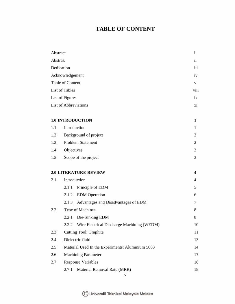
TABLE OF CONTENT
Abstract i
Abstrak ii
Dedication iii
Acknowledgement iv
Table of Content v
List of Tables viii
List of Figures ix
List of Abbreviations xi
1.0 INTRODUCTION 1
1.1 Introduction 1
1.2 Background of project 2
1.3 Problem Statement 2
1.4 Objectives 3
1.5 Scope of the project 3
2.0 LITERATURE REVIEW 4
2.1 Introduction 4
2.1.1 Principle of EDM 5
2.1.2 EDM Operation 6
2.1.3 Advantages and Disadvantages of EDM 7
2.2 Type of Machines 8
2.2.1 Die-Sinking EDM 8
2.2.2 Wire Electrical Discharge Machining (WEDM) 10
2.3 Cutting Tool: Graphite 11
2.4 Dielectric fluid 13
2.5 Material Used In the Experiments: Aluminium 5083 14
2.6 Machining Parameter 17
2.7 Response Variables 18
2.7.1 Material Removal Rate (MRR) 18
vi
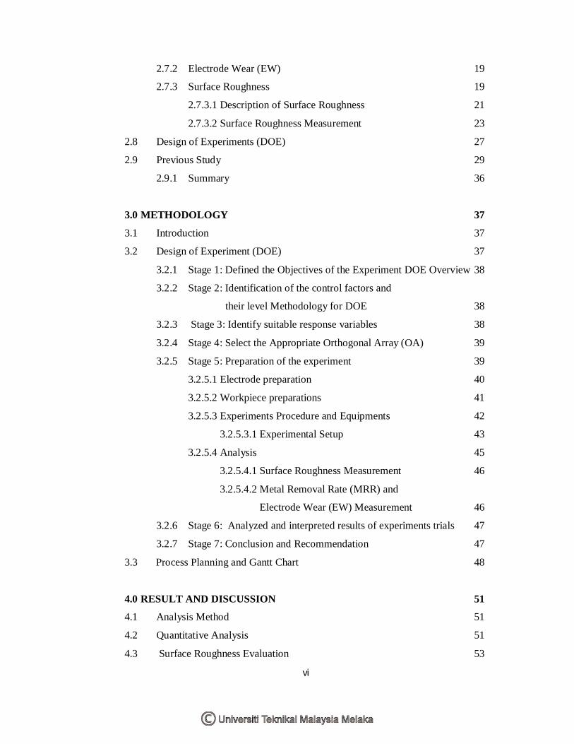
2.7.2 Electrode Wear (EW) 19
2.7.3 Surface Roughness 19
2.7.3.1 Description of Surface Roughness 21
2.7.3.2 Surface Roughness Measurement 23
2.8 Design of Experiments (DOE) 27
2.9 Previous Study 29
2.9.1 Summary 36
3.0 METHODOLOGY 37
3.1 Introduction 37
3.2 Design of Experiment (DOE) 37
3.2.1 Stage 1: Defined the Objectives of the Experiment DOE Overview 38
3.2.2 Stage 2: Identification of the control factors and
their level Methodology for DOE 38
3.2.3 Stage 3: Identify suitable response variables 38
3.2.4 Stage 4: Select the Appropriate Orthogonal Array (OA) 39
3.2.5 Stage 5: Preparation of the experiment 39
3.2.5.1 Electrode preparation 40
3.2.5.2 Workpiece preparations 41
3.2.5.3 Experiments Procedure and Equipments 42
3.2.5.3.1 Experimental Setup 43
3.2.5.4 Analysis 45
3.2.5.4.1 Surface Roughness Measurement 46
3.2.5.4.2 Metal Removal Rate (MRR) and
Electrode Wear (EW) Measurement 46
3.2.6 Stage 6: Analyzed and interpreted results of experiments trials 47
3.2.7 Stage 7: Conclusion and Recommendation 47
3.3 Process Planning and Gantt Chart 48
4.0 RESULT AND DISCUSSION 51
4.1 Analysis Method 51
4.2 Quantitative Analysis 51
4.3 Surface Roughness Evaluation 53
vii
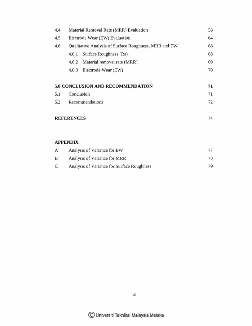
4.4 Material Removal Rate (MRR) Evaluation 58
4.5 Electrode Wear (EW) Evaluation 64
4.6 Qualitative Analysis of Surface Roughness, MRR and EW 68
4.6.1 Surface Roughness (Ra) 68
4.6.2 Material removal rate (MRR) 69
4.6.3 Electrode Wear (EW) 70
5.0 CONCLUSION AND RECOMMENDATION 71
5.1 Conclusion 71
5.2 Recommendations 72
REFERENCES 74
APPENDIX
A Analysis of Variance for EW 77
B Analysis of Variance for MRR 78
C Analysis of Variance for Surface Roughness 79
viii
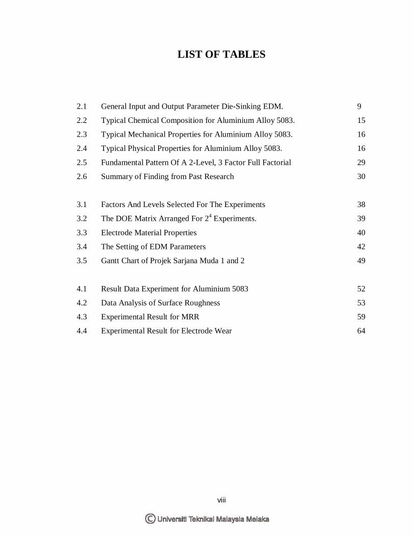
LIST OF TABLES
2.1 General Input and Output Parameter Die-Sinking EDM. 9
2.2 Typical Chemical Composition for Aluminium Alloy 5083. 15
2.3 Typical Mechanical Properties for Aluminium Alloy 5083. 16
2.4 Typical Physical Properties for Aluminium Alloy 5083. 16
2.5 Fundamental Pattern Of A 2-Level, 3 Factor Full Factorial 29
2.6 Summary of Finding from Past Research 30
3.1 Factors And Levels Selected For The Experiments 38
3.2 The DOE Matrix Arranged For 24 Experiments. 39
3.3 Electrode Material Properties 40
3.4 The Setting of EDM Parameters 42
3.5 Gantt Chart of Projek Sarjana Muda 1 and 2 49
4.1 Result Data Experiment for Aluminium 5083 52
4.2 Data Analysis of Surface Roughness 53
4.3 Experimental Result for MRR 59
4.4 Experimental Result for Electrode Wear 64
ix
LIST OF FIGURES
1.1 Die-Sinking EDM (MODEL: AQ35L SODICK). 2
2.1 A Schematic View of a Die-Sinking EDM System. 10
2.2 Wire Electrical Discharge Machining (WEDM). 11
2.3 Graphite Electrode Used In This Experiment. 13
2.4 Profiles In Surface Appeared On The Workpiece. 20
2.5 Checking Profile on Surface Using Stylus Method. 22
2.6 Determination of Ra (m is the mean line). 23
2.7 Electronic Speckle Correlation Using Lens. 24
2.8 Measuring Surface Roughness with a Stylus. 26
2.8 Surface Measuring Instrument (Surface Roughness Tester SJ – 301) 26
2.9 Profilometer Mitutoyo Surf test SJ-301. 26
2.10 Schematic Figure Checking Roughness Using Stylus Method. 27
3.1 Graphite electrode used in this experiment. 40
3.2 EDM Die-Sinking (MODEL: SODICK LN2/LQ Series) 43
3.3 Power Supply Provides Volts and Amps 44
3.4 Sparks Causes The Material To Melt And Vaporize. 44
3.5 Pressurized Dielectric Oils Remove The EDM Chips. 45
3.6 Part Design after EDMed Process and Specimen to Analyze. 45
3.7 The Measurement Performed On the Specimen 46
3.7 Result printed. 46
3.8 The weight of electrode and workpiece were measured by
using the digital weight machine 47
3.9 Flow Chart for Project Methodology 48
4.1 Normal Probability Plot Of Effects For Surface Roughness 54
4.2 Pareto Chart of the Effects for Surface Roughness 55
x
4.3 Main Effects Plot for Ravg 55
4.4 Interaction Plot for Ravg 56
4.5 Estimate Response Surface of Ra Vs. Current, Off-Time 57
4.6 Estimated Response Surface of Ra Vs. Current, Pulse On-Time 57
4.7 Estimated Response Surface of Ravg Vs. Current, Voltage 58
4.8 Normal Probability Plot of Effects for MRR 60
4.9 Pareto Chart of the Effects for MRR 60
4.10 Main Effects Plot for MRR 61
4.11 Interaction Plot for MRR 62
4.12 Estimated Response Surface of MRR vs. Peak Current, On-Time 63
4.13 Estimated Response Surface of MRR vs. Peak Current, Voltage 63
4.14 Normal Probability Plot of Effects for EW 65
4.15 Pareto Chart of the Effects to EW 65
4.16 Main Effects Plot for EW 66
4.17 Interaction Plot for EW 67
4.18 Estimated Response Surface of EW vs. Peak Current, Voltage 67
xi
LIST OF ABBREVIATIONS
ANOVA - Analysis of Variance
BP - Belief propagation
CNC - Computer Numerical Control
DOE - Design of experiments
EDM - Electric discharge machining
EDG - Electrical discharge grinding
EW - Electrode wear
GA - Genetic algorithm
HV - Hardness Vickers
K - Kurtosis
MRR - Material removal rate
NTM - Non-traditional manufacturing
Rms - Root-mean-square
Ra - Average roughness
Rv - The maximum valley height
Rq - Root mean square roughness
Ry or Rmax - Maximum peak-to-valley roughness
Rp - Maximum peak height
Sk - Skewness
TFM - Total Form Machining
UTeM - Universiti Teknikal Malaysia Melaka
WEDM - Wire Electric discharge machining
η - Duty cycle
1
CHAPTER 1 INTRODUCTION
1.1 Introduction Electric discharge machining (EDM) is among the earliest of non-traditional
manufacturing (NTM) process, having had its inception 50 years ago in a simple die-
sinking application. The two principal types of EDM are die-sinking EDM and wire
EDM (WEDM). Die-sinking EDM is traditionally performed vertically, but it may also
be conducted horizontally. Die-sinking EDM has been greatly refined since the 1940s
with the advent of transistorized pulse generators, planetary and orbital motion
techniques, CNC and adaptive control. Orbital motion was introduced to EDM during
the early 1970s. Orbital motion is composed of simultaneous electrode movement along
the vertical axis with a lateral movement out of the work piece center. Thus the electrode
center describes a horizontal circular orbit. This orbit is characterized by the eccentricity
and the angular speed of the translation. The former is controlled by the servo system
just like the vertical speed feed, while the angular speed of the translation can be chosen
freely. Another application of electrical discharges machining (EDM) is electrical
discharge grinding (EDG), which is used for precision machining of electrically
conductive workpieces. The EDM state-of-the-art practice achieved significant
technological breakthroughs during the late 1980s owing to two major advances:
improvement in the performance of the EDM process and advancements in the level of
automation for EDM. The EDM process has been improved by reduced damage from
arcing, lowered tool wear ratio and less frequent wire rupture in WEDM. The level of
automation has increased through on-line adaptive control strategies.
2
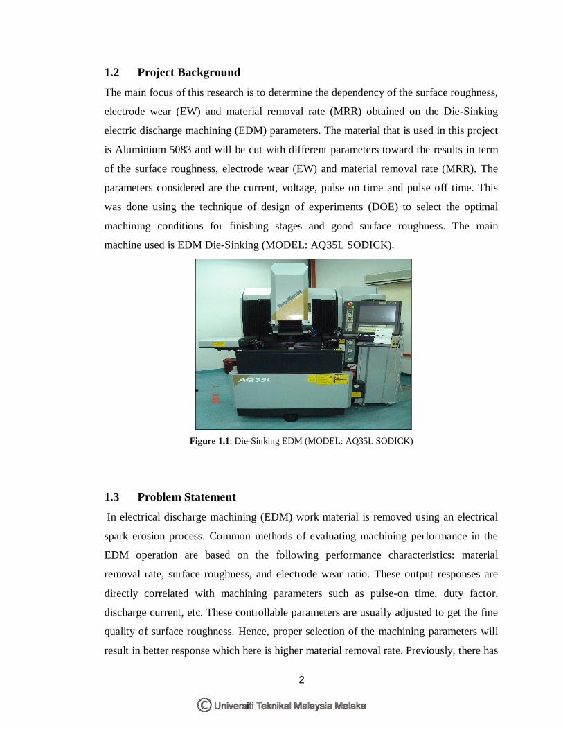
1.2 Project Background The main focus of this research is to determine the dependency of the surface roughness,
electrode wear (EW) and material removal rate (MRR) obtained on the Die-Sinking
electric discharge machining (EDM) parameters. The material that is used in this project
is Aluminium 5083 and will be cut with different parameters toward the results in term
of the surface roughness, electrode wear (EW) and material removal rate (MRR). The
parameters considered are the current, voltage, pulse on time and pulse off time. This
was done using the technique of design of experiments (DOE) to select the optimal
machining conditions for finishing stages and good surface roughness. The main
machine used is EDM Die-Sinking (MODEL: AQ35L SODICK).
Figure 1.1: Die-Sinking EDM (MODEL: AQ35L SODICK)
1.3 Problem Statement In electrical discharge machining (EDM) work material is removed using an electrical
spark erosion process. Common methods of evaluating machining performance in the
EDM operation are based on the following performance characteristics: material
removal rate, surface roughness, and electrode wear ratio. These output responses are
directly correlated with machining parameters such as pulse-on time, duty factor,
discharge current, etc. These controllable parameters are usually adjusted to get the fine
quality of surface roughness. Hence, proper selection of the machining parameters will
result in better response which here is higher material removal rate. Previously, there has
3
been no significance study on Die-sinker EDM using Aluminium 5083 with graphite as
the electrode. In this study, the investigation is focused on effect of various parameters
on Die-sinker EDM machining on Aluminium 5083 using graphite electrode. This
experiment also tries to get which parameter that affects the most in cutting Aluminium
5083.
1.4 Objectives
The main objectives of this study are as the following:
(a) To gain basic knowledge on advance machining.
(b) To know basic principles of Die-Sinking EDM.
(c) To determine basic machining characteristic of Die-Sinking EDM.
(d) To apply statistical analysis of experiment (DOE) using suitable designs method to
select the best parameter combination.
1.5 Scope of the Project The scopes of the work in order to achieve the main objective are:
(a) Using Aluminium 5083 as a workpiece material.
(b) Using Graphite as an electrode.
(c) Study the parameters involve in this study such as current, voltage, pulse on time and
pulse off time.
(d) Implementing design of experiment (DOE) method to analyze the results.
4
CHAPTER 2 LITERATURE REVIEW
The following sections present discussions on topics related with Die-sinking EDM
process such as the concept of Die-sinking EDM technology, the machining parameters
and the material used. At the end of the chapter, several results of previous study are
presented.
2.1 Introduction In the past fifty years, EDM and wire EDM have made tremendous increases in the
manufacturing field. Puertas & Perez [9] state “EDM is a widespread technique used in
industry for high precision machining of all types of conductive materials such as
metals, metallic alloys, graphite, or even some ceramic materials, of any hardness”. Also
EDM process is used in various fields and industries such as the medical field,
construction, automotive, and aeronautics and space. Puertas and Perez explain that
there are two basic types of EDM: die-sinking and wire EDM. Die-sinking EDM
reproduces the shape of the tool used (electrode) in the part being machined, whereas in
wire EDM a metal wire (electrode) is used to cut a programmed outline into the piece
being machined.
Electrical Discharge Machining, EDM is one of the most accurate manufacturing
processes available for creating complex or simple shapes and geometries within parts
and assemblies. The main limitation of EDM is that it can only cut materials that are
electrically conductive. The EDM process is commonly used in the tool and dies
5
industry for mold-making, however in recent years EDM has become an integral part for
making prototype and production parts.
Besides, EDM (electrical discharge machining) is a machining method primarily used
for hard metals or those that would be impossible to machine with traditional techniques.
EDM can cut small or odd-shaped angles, intricate contours or cavities in extremely
hard steel and exotic metals such as iconel, hastelloy, kovar, titanium and carbide.
Sometimes referred to as spark eroding or spark machining, EDM is a method of
removing material by a series of rapidly recurring electric arcing discharges between an
electrode (the cutting tool) and the work piece, in the presence of an energetic electric
field.
The EDM cutting tool is guided along the desired path very close to the work but it does
not touch the piece. Rapidly occurring consecutive sparks produce a series of micro-
craters on the work piece and remove material along the cutting path by melting and
vaporization. The constantly flushing dielectric fluid washes away the particles. The
EDM Machining process is becoming a common method of making production and
prototype parts, though it has been most widely used by the mold-making tool and dies
industries. Particularly in the aerospace and electronics industries in which production
quantities are relatively low.
2.1.1 Principle of EDM
The basic principle behind EDM machines dates back to the fifty years ago. They
basically work in one of two ways: "they cut metal with a special metal wire electrode
that is programmed to travel along a preprogrammed path (in the case of wire EDM), or
they form a required shape negatively in a metal using a three dimensional electrode in
the case of die sinking EDM machines [4]. EDM uses a charged electrode, and then
brings the electrode near a workpiece (oppositely charged). As the tool and the
workpiece get close enough, a spark will occur in dielectric fluid. The sparks then create
a hole in both the electrode and the workpiece.
6
Some of the different types of materials used for electrodes are: copper, tungsten, and
graphite. Although all these materials are used as electrodes, graphite is the most
commonly used material because it is less affected and warn from the process. Graphite
also is machined very easily, conducts electricity, and does not vaporize. During the
process, the discharges that reveal the “spark” create the crater-like surface on the
workpiece [1].
When explaining the workpiece and the tool being used, the terms, anode and cathode
are the proper vocabulary terms used. The tool during the EDM process is shaped to the
detailed required. The positive electrode and the negative electrode never touch each
other, and a small gap is maintained at all times between the two electrodes by a
computer. Both electrodes are inundated into dielectric fluid and create a course for the
electric discharge to be made. Dielectric fluid is normally a clear color, some
manufacturers will slightly dye their brand to make it unique. All EDM fluids have a
high dielectric strength. Dielectric strength is important while a high value of strength is
required, too high of a value will force a smaller gap and could lead to a higher wear on
the electrode. Most quality dielectric fluids will be odorless but there are some that do
produce an odor which generally means the quality isn't as high. There are petroleum
and sythetic oils for EDM [2]. The dielectric fluid allows the tool to cool and removes
any waste products remaining. The dielectric fluid is critical in coming out with a good
surface finish because it controls the discharge [3].
2.1.2 EDM Operation
Operating the EDM machine is not as difficult as the process itself. Puertas & Perez [9]
explain: Electrical discharge machining (EDM) is a non-traditional manufacturing
process based on removing material from a part by means of a series of repeated
electrical discharges (created by electric pulse generators at short intervals) between a
tool, called the electrode, and the part being machined in the presence of a dielectric
fluid.
7
When operating EDM, there are two designs for the tool feed: ram and quill. The ram-
feed machines are more heavy duty and less expensive than the quill-feed. The ram-feed
uses a hydraulic cylinder for the movement of the head, whereas the quill-feed uses a
hydraulic motor to drive a leadscrew. Both are controlled by “advancing and retracting
the tool” [5]. Not only are the designs different, but there are also a large number of
factors to consider within the EDM process, such as the level of generator intensity, the
pulse time, and the duty cycle.
Puertas & Perez [9] clarify, “The level of generator intensity represents the maximum
value of the discharge current intensity. The pulse time is the duration of time that the
current is allowed to flow per cycle, and the duty cycle is the percentage of the pulse
time relative to the total cycle time.
In addition, none of these processes within EDM require force, because the anode never
touches the cathode. Another factor to consider in the EDM process is the speed of
material removal. The speed of the material removal process as in most cases is
measured by cubic inches per hour. The EDM process does not require force. There are
several factors that control the material removal rate. The most important of these is the
melting temperature of the workpiece material. The lower the melting temperature, the
faster the removal rate. The rate of which the electrode is eroded is also considered.
“Erosion rates are not affected by the material hardness but by the melting temperature
of the material being used” [6].
2.1.3 Advantages and Disadvantages of EDM
EDM is a method of machining parts that cannot be done by conventional machines.
“Since the tool does not touch the workpiece, there are no cutting forces generated;
therefore, very fragile parts can be machined” [7]. The shape and also the hardness of
the materials being used make EDM ideal. The EDM process leaves no burrs and the
material is flushed away by the dielectric fluid, and by eliminating extra steps it also
lowers costs. EDM makes it ideal for small, lots of parts, allowing reducing operating
8
expenses, delivery dates, or reducing inventory. EDM can replace many types of contour
grinding operations and eliminate secondary operations such as deburring and polishing.
EDM is at an advantage when secondary operations are too labor intensive for
traditional machines.
In addition, some of the advantages of EDM include machining of complex shapes that
would otherwise be difficult to produce with conventional cutting tools, extremely hard
material to very close tolerances, very small work pieces where conventional cutting
tools may damage the part from excess cutting tool pressure. However EDM also have
some disadvantages like inability to machine non-conductive materials, slow rate of
material removal, additional time and cost used for creating electrodes for Die-Sinker
EDM and reproducing sharp corners on the workpiece is difficult due to electrode wear.
2.2 Types of machines There are two types of EDM processes namely wire and die sinker (also called
Conventional EDM and Ram EDM). Wire EDM uses a metal wire as the tool electrode.
It can generate two or three dimensional shapes on the workpiece for making punch dies
and other mechanical parts. Die sinker are generally used for complex geometries where
the EDM machine uses a machined graphite or copper electrode to erode the desired
shape into the part or assembly.
2.2.1 Die-Sinking EDM
The Die-sinker EDM machining process uses an electrically charged electrode that is
configured to a specific geometry to burn the geometry of the electrode into a metal
component. The sinker EDM process is commonly used in the production of dies and
molds. Over the past few years, advances in the field of EDM have allowed the
manufacturing of ceramic materials. The main inconvenience with the die-sinking EDM
is the electrical conductivity of the ceramic material. There are different variables when
using the EDM for ceramic materials, such as: "surface roughness, material removal
9
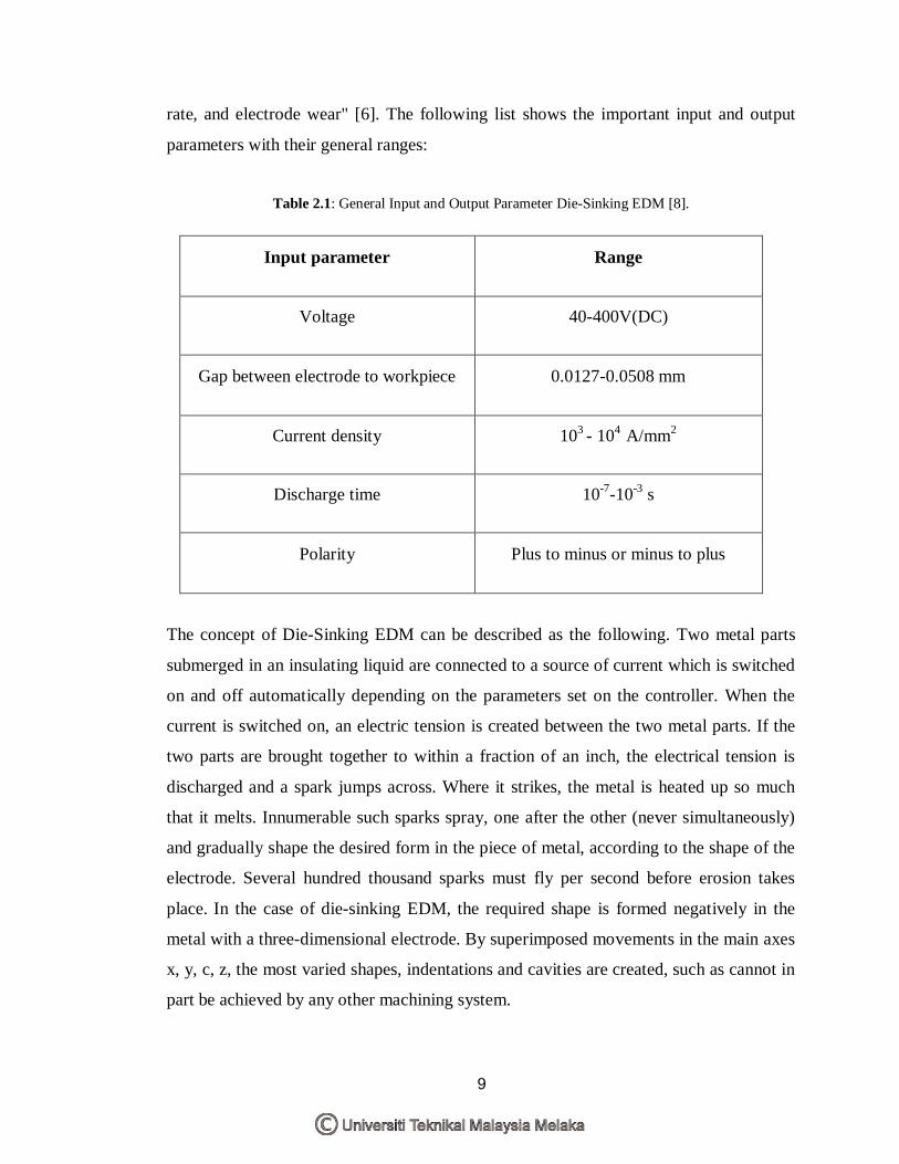
rate, and electrode wear" [6]. The following list shows the important input and output
parameters with their general ranges:
Table 2.1: General Input and Output Parameter Die-Sinking EDM [8].
Input parameter Range
Voltage 40-400V(DC)
Gap between electrode to workpiece 0.0127-0.0508 mm
Current density 103 - 104 A/mm2
Discharge time 10-7-10-3 s
Polarity Plus to minus or minus to plus
The concept of Die-Sinking EDM can be described as the following. Two metal parts
submerged in an insulating liquid are connected to a source of current which is switched
on and off automatically depending on the parameters set on the controller. When the
current is switched on, an electric tension is created between the two metal parts. If the
two parts are brought together to within a fraction of an inch, the electrical tension is
discharged and a spark jumps across. Where it strikes, the metal is heated up so much
that it melts. Innumerable such sparks spray, one after the other (never simultaneously)
and gradually shape the desired form in the piece of metal, according to the shape of the
electrode. Several hundred thousand sparks must fly per second before erosion takes
place. In the case of die-sinking EDM, the required shape is formed negatively in the
metal with a three-dimensional electrode. By superimposed movements in the main axes
x, y, c, z, the most varied shapes, indentations and cavities are created, such as cannot in
part be achieved by any other machining system.