universiti teknikal malaysia...
TRANSCRIPT
UNIVERSITI TEKNIKAL MALAYSIA MELAKA
DEVELOPMENT OF PROCESS FLOW AND STANDARD
OPERATING PROCEDURES FOR MADEENA SYRUP
PROCESS CONTROLS
This report submitted in accordance with requirement of the Universiti Teknikal
Malaysia Melaka (UTeM) for the Bachelor Degree of Manufacturing Engineering
(Robotic and Automation)
by
MUHAMMAD SYAFIQ BIN SAMSUDIN
B050710150
FACULTY OF MANUFACTURING ENGINEERING
2011
Alamat Tetap:
697D Jalan Perak 5,
Taman Megah Bukit Beruang,
75450 Ayer Keroh, Melaka.
Tarikh:__________________
UNIVERSITI TEKNIKAL MALAYSIA MELAKA
BORANG PENGESAHAN STATUS LAPORAN PROJEK SARJANA MUDA
TAJUK: Development Of Process Flow And Standard Operating
Procedures For Madeena Syrup Process Controls.
SESI PENGAJIAN: 20010/11 Semester 2
Saya MUHAMMAD SYAFIQ BIN SAMSUDIN
mengaku membenarkan Laporan PSM ini disimpan di Perpustakaan UniversitiTeknikal Malaysia Melaka (UTeM) dengan syarat-syarat kegunaan sepertiberikut:
1. Laporan PSM adalah hak milik Universiti Teknikal Malaysia Melaka danpenulis.
2. Perpustakaan Universiti Teknikal Malaysia Melaka dibenarkan membuatsalinan untuk tujuan pengajian sahaja dengan izin penulis.
3. Perpustakaan dibenarkan membuat salinan laporan PSM ini sebagaibahan pertukaran antara institusi pengajian tinggi.
4. **Sila tandakan (√)
(Mengandungi maklumat TERHAD yang telahditentukan oleh organisasi/badan di manapenyelidikan dijalankan)
(Mengandungi maklumat yang berdarjahkeselamatan atau kepentingan Malaysia yangtermaktub di dalam AKTA RAHSIA RASMI 1972)
TIDAK TERHAD
TERHAD
SULIT
Disahkan oleh:
PENYELIA PSM
Tarikh: ______________
** Jika Laporan PSM ini SULIT atau TERHAD, sila lampirkan surat daripada pihakberkuasa/organisasi berkenaan dengan menyatakan sekali sebab dan tempohlaporan PSM ini perlu dikelaskan sebagai SULIT atau TERHAD.
DECLARATION
I hereby, declared this report entitled “Development Of Process Flow And
Standard Operating Procedures For Madeena Syrup Process Controls” is the results
of my own research except as cited in references.
Signature : …………………………………………......
Author’s Name : MUHAMMAD SYAFIQ BIN SAMSUDIN
Date : 18 MEI 2011
APPROVAL
This report is submitted to the Faculty of Manufacturing Engineering of UTeM
as a partial fulfillment of the requirements for the Degree in Bachelor of
Manufacturing Engineering (Robotic and Automation). The member of the
supervisory committee is as follow:
………………………………
Supervisor
i
ABSTRAK
Projek ini merupakan suatu projek bagi membangunkan atau meningkatkan
aliran proses dan prosedur operasi standard untuk proses kawalan sirap
Madeena. Projek ini memerlukan kami untuk membina sebuah mesin yang akan
menapis sirap untuk meingkatkan kualiti sirap tersebut dengan mengurangkan
bendasing atau bahan kimia didalamnya. Projek dimulakan dengan kajian tentang
bendalir, dan prosedur operasi bagi sesuatu proses. Selain itu, litar elektrik untuk
mesin ini juga perlu dibina bagi membolehkan mesin ini beroperasi seperti apa yang
dirancangkan. Beberapa proses terlibat dalam membina mesin ini seperti
menggergaji, menggerudi, menyambung permukaan-permukaan, serta proses
mewarnakan mesin menggunakan cat. Litar elektrik yang dibina diuji menggunakan
perisian computer iaitu “Automation Studio”. Apabila mesin siap dibina, ianya diuji
terlebih dahulu menggunakan air sebanyak beberapa kali bagi mengenalpasti
samaada mesin itu boleh berfungsi sepenuhnya dan tiada sebarang kebocoran
disepanjang sambungan. Kemudian, mesin diuji lagi dengan menggunakan sirap dan
data direkod bagi membandingkan kadar kelajuan diantara air dan sirap. Apabila
semua data telah direkodkan dan semua bocoran telah dibaiki maka mesin sudah siap
dibina. Langkah terakhir adalah menyediakan prosedur operasi penggunaan mesin
untuk rujukan para pekerja bagi mengendalikan mesin dengan betul dan selamat.
ii
ABSATRACT
This project presents the development of process flow and standard operating
procedures for madeena syrup process controls. This project is need for build a
machine that will filter the syrup liquid in order to improve their quality by removing
the contaminants. The development starts with the study about fluid, pump, feed rate
and also the standard operating procedure (SOP). In this development also, the study
about the circuit and simulation on them are also required since we want it operates
according what has been planned. The machine is build by undergo a few process
such as wiring, welding, sawing, and also finishing process. Then, the circuit is test
using Automation Studio by simulate them. When the machine is complete, the first
test using water is run and the data is recorded. Second test is using the syrup liquid
that is the objective of this project. All the record data of the feed rate, quality,
process flow and operating procedure is analyzed and documented. Thus, the
machine is complete and also included with the SOP that very useful for the operator
to operate machine rightly.
iii
ACKNOWLEDGEMENT
Bimillahirrahmanirrahim…
I wish to express my sincere thanks to Universiti Teknikal Malaysia Melaka (UTeM)
as a university that I’ve already been through about 4 years as a student in degree and
I really grateful to have been here as a student that always determining to succeed in
the future. I also would like to extend my very special thanks to my beloved parents,
Mr. Samsudin Bin Sueet and Mrs. Norshalimar Bte Mohd Ali for their full support
and their guidance that really makes me stronger and stronger each day, each week,
each month and each year to surpass all the barriers in life to succeed in the future.
Without their prayer and blessing, I would possibly give up with my studies. As the
most important and respected man that always support me in this project, Mr. Ahmad
Yusiri Bin Bani Hashim, I would like to thank for his excellent supervised, giving
good suggestion and criticism to the process of the work and motivates me in a good
way which makes me improve myself in life or in studies. My appreciation also give
to the technicians which help me built the machine according to the given period of
time. They have teach me a lot in build the machine and also teach me how to do a
few manufacturing process.
MUHAMMAD SYAFIQ BIN SAMSUDIN
TABLE OF CONTENT
iv
Abstract i
Acknowledgement ii
Table of Content iii
List of Figures vi
List of Tables x
List of Abbreviations xi
1. INTRODUCTION 1
1.1 Background 1
1.2 Problem Statement 4
1.3 Objectives of the Project 5
1.4 Scope of the Project 5
2. LITERATURE REVIEW 6
2.1 Fluid Mechanic 6
2.1.1 Introduction to Fluid Mechanic 6
2.1.2 Definition of fluid 8
2.1.3 Bernoulli’s Principle 9
2.1.4 Basic equation in analyzing problem of fluid mechanics problem. 10
2.2 Filtration 11
2.2.1 Definition of Filtration 11
2.2.2 Applications of Filtration 12
2.2.3 Filtration Methods 13
2.2.3.1 Distillation 13
2.2.3.2 Ion Exchange 14
2.2.3.3 Carbon Adsorption 15
2.2.3.4 Microporous Basic Filtration 17
2.2.3.5 Reverse Osmosis 18
2.2.4 Types of Filters 20
2.2.5 Liquid Filtration 20
2.2.6 Machines Of Filteration System That Already In Market 22
2.2.6.1 Syrup Filter 22
2.2.6.2 Pure Water Diatomite Filter 23
v
2.2.7 Research done by ONTARIO 24
2.2.7.1 Introduction of Maple Sap Syrup 24
2.2.7.2 Problems in Maple Sap 26
2.2.7.3 Filtration of Maple Sap 27
2.2.7.4 History of Filtration of Maple Sap 28
2.2.7.5 Types of Sap Filters 31
2.2.7.6 Gravity Sap Filters 32
2.2.7.7 Pressure Sap Filters 35
2.3 Standard Operating Procedure 38
2.3.1 Introduction to Standard Operating Procedure 38
2.3.2 Benefits of applying SOP. 39
2.3.3 Writing Format of SOP. 39
2.3.4 SOP need to be Review and Approve 40
2.3.5 Frequency of Revisions and Reviews 40
2.3.6 Five Obstacles that SOP development leader should be aware. 41
2.3.7 Variation in Process 42
2.3.8 Example of SOPs 43
2.4 Pump 48
2.4.1 Introduction of Pump 48
2.4.2 The Principle of Operation of Pump 48
2.4.2.1 Kinetic (Centrifugal) Pump 48
2.4.2.2 Positive Displacement Pump 50
2.4.3 Analogy of Cntrifugal & Positive-Displacement Pumps 52
2.4.4 Comparison Table – Centrifugal vs. Positive Displacement Pumps 54
3. METHODOLOGY 55
3.1 Source of Information 55
3.2 Flow of Development 55
3.3 Gantt Chart 64
3.4 Application of Automation Studio Software 64
4. DEVELOPMENT OF ROBOT MOVEMENT 65
4.1 Modeling 65
4.2 Manufacturing Process 66
4.2.1 Drilling and Roughing Process (DB Box) 66
vi
4.2.2 Wiring Process (DB box circuit) 67
4.2.3 Drilling and Joining Process 68
4.2.4 Sawing and Rivet Process 70
4.2.5 Finishing Procrss 71
4.2.6 Complete Filtration Machine 73
4.2.7 Layout of location 74
4.3 Flow of the current in the circuit 75
4.3.1 Complete electric circuit that have been built using automation
studio. 75
4.3.2 Algebric Representation 76
4.4 Flow of liquid in the pipeline 78
4.5 Standard Operating Procedure 80
4.5.1 Syrup Handling Procedure 80
4.5.2 Machine Standard Operating Procedure 84
5. RESULT OF DEVELOPMENT 90
5.1 Simulation of Electric Circuit 90
5.1.1 The complete electric circuit that have been built using automation
studio. 90
5.1.2 Simulation of the electric circuit. 91
5.2 The flow of Syrup liquid 94
5.3 Feed rate 97
5.3.1Feed Rate of Water 97
5.3.2 Feed Rate of Syrup 98
6. ANALYSIS AND DISCUSSION 99
6.1Analysis of The Flow of the Syrup Liquid 99
6.1.1 Flow of syrup 99
6.1.2 Feed Rate 100
6.2 Condition of workers. 101
6.3 The Standard Operating Procedure (SOP) 101
6.4 Production of Syrup Liquid 102
6.5 Quality of the Syrup Liquid 102
6.6 Improvement and development 103

vii
7. CONCLUSION AND RECOMMENDATION 105
7.1 Conclusion 105
7.2 Recommendation 106
REFERENCES 107
APPENDICES
A Types of Filters
B Comparison Table of Centrifugal vs. Positive Displacement Pumps
C Gant Chart Semester 1
D Gant Chart Semester 2
E Steps of Automation Studio Simulation
viii
LIST OF FIGURES
1.1 The product of the Madeena Enterprise 1
1.2 The pot that use to cook he syrup 2
1.3 The bottle use to fill the syrup 3
1.4 Bottles that already full with syrup 3
2.1 Difference in behavior of solid and a fluid due to shear force 8
2.2 Oversize solids in the fluid that are retained on filter 11
2.3 Schematic diaghram of distillation process 13
2.4 Schematic diaghram of Ion Exchange process 15
2.5a Schematic diaghram of Carbon Adsorption process 16
2.5b Schematic diaghram of microporous basic filtration process 17
2.5c Schematic diaghram of microporous basic filtration process 17
2.6 Osmotic pressure drives water through the membrane 20
2.7 Schematic diaghram of Reverse Osmosis process 20
2.8 Bottled maple syrup produced in Quebec 26
2.9 US Syrup grades. Left to right: Light Amber(Vermont Fancy), Grade A
Medium Amber, Grade A Dark Amber, Grade B 27
2.10 In-line ultraviolet sterilizing units are effective in killing bacteria and
other microorganisms in sap. Research has found them more effective
in destroying bacteria than yeasts 30
2.11 Reverse Osmosis machines are equipped with one or more in-line sap
filters to remove contaminants prior to concentrating sap 31
2.12 Commercial gathering tanks are equipped with a metal strainer for
removing ice, bark, leaves, wood chips and other coarse particles 34
2.13 Pop sap filters are used to remove coarse particles from the sap prior to
storage 35
2.14 In-line sap filters are commonly called small pore filters. They are
effective in removing contaminants including some microorganisms 36
ix
2.15 Diatomaceous Earth (D.E.) sap filters are the most recent filter type
used for sap filtering. They can trap tiny particles as well as some
microorganisms. 38
2.16 Types of Centrifugal Pump 51
2.17 Types of Positive-Displacement Pump 53
2.18 Major Pump Categories 55
3.1 Flow Chart of the Development 58
3.2 Flow Chart of Production rate of the liquid 60
3.3 Flow Chart of Quality of filtered liquid 62
3.4 Flow Chart of Standard Operating Procedure 64
4.1 Modeling of the machine 67
4.2.1a Tool to mark DB box 68
4.2.1b Mark DB box 68
4.2.1c Drilling Machine 68
4.2.1d Drill Bit (Saw) 68
4.2.1e Marked DB box 68
4.2.1f Bottom of DB box 68
4.2.1g Door of DB box 69
4.2.1h Pressure miserly 69
4.2.2a Connecter gripped by vise 69
4.2.2b Connector that gripped to wire 69
4.2.2c Connection of wire 69
4.2.2d Checking wiring 69
4.2.2e Connect wire to plug 70
4.2.2f Complete DB box 70
4.2.2g Wrapping Bands 70
4.2.3a Technician show how to drill 70
4.2.3b Joining Process by using bolts and nut 70
4.2.3c DB box that have been installed 71
4.2.3d Pump holder 71
4.2.3e Diaphragms Pump 71
x
4.2.3f Filter 71
4.2.3g Filter 71
4.2.3h Tank 1and Tank 2 71
4.2.4a Plywood that will be use 72
4.2.4b Pressure Rivet 72
4.2.4c Hinge use to connect 72
4.2.4d Plywood that has been joined 72
4.2.4e Marked plywood 72
4.2.4f Sawing Process 72
4.2.4g Sawing process 73
4.2.4h Plywood ready to paint 73
4.2.5a Blue Paint 73
4.2.5b Paint Brush 73
4.2.5c 1st layer of paint 73
4.2.5d 2nd layer of paint 73
4.2.5e Locker pin 74
4.2.5f Locker pin that has been rivet 74
4.2.5g Complete Finishing Process 74
4.7 Layout of location 75
4.8 Layout of location 76
4.9 Electric circuit of the Madeena filtration machine 77
4.10 The flow of the liquid in the pipeline 80
5.1 Electric circuit of the Madeena filtration machine 92
5.2 The syrup liquid fill up the filter 1 96
5.3 The syrup liquid fill up the filter 2 96
5.4 The syrup liquid fill up the filter 3 97
5.5 The syrup liquid fill up tank B 97
5.6 The syrup liquid fill up the testing bottle 98
6.1 Bar Chart of Feed rate of water and syrup liquid 103
6.2 The syrup liquid that has been filter by Machine (Sign1) and Tradionally 106
xi
LIST OF TABLES
4.1 Equation 1 78
4.2 Equation 2 78
4.3 Equation 3 79
4.4 Equation 4 79
5.1 Feed rate of the water flow at stations 99
5.2 Feed rate of Syrup Liquid 100
xii
LIST OF ABBREVIATIONS
SOP - Standard Operating Procedure
RO - Reverse Osmosis
DI - Deionization
TCE - Trichloroethylene
TDS - Total Dissolve Solids
ONTARIO - Ministry of Agriculture Food and Rural Affairs, France
D.E. - Diatomaceous Earth
1
CHAPTER 1INTRODUCTION
1.1 Background
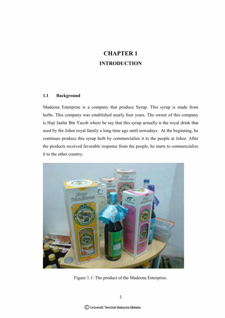
Madeena Enterprise is a company that produce Syrup. This syrup is made from
herbs. This company was established nearly four years. The owner of this company
is Haji Jaafar Bin Yacob where he say that this syrup actually is the royal drink that
used by the Johor royal family a long time ago until nowadays. At the beginning, he
continues produce this syrup herb by commercialize it to the people at Johor. After
the products received favorable response from the people, he starts to commercialize
it to the other country.
Figure 1.1: The product of the Madeena Enterprise.
2
From the time passes, he realized that his process in making the syrup, need to be
improve because of a few factors. First factor is about the work need to be done by
the worker. The existing process requires high labor. This is because they have to fill
in the plastic or glass bottle manually. So, if the reservation is high, they have to
work hard in order to achieve the target in the period of time that has been given.
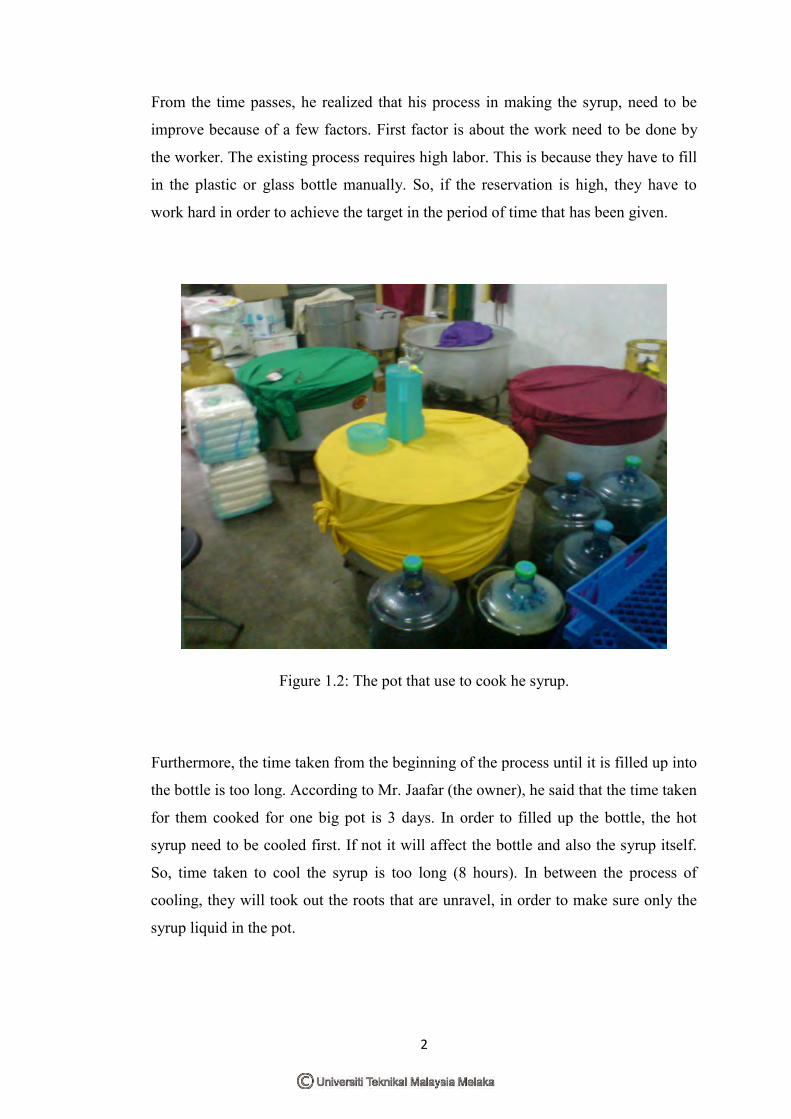
Figure 1.2: The pot that use to cook he syrup.
Furthermore, the time taken from the beginning of the process until it is filled up into
the bottle is too long. According to Mr. Jaafar (the owner), he said that the time taken
for them cooked for one big pot is 3 days. In order to filled up the bottle, the hot
syrup need to be cooled first. If not it will affect the bottle and also the syrup itself.
So, time taken to cool the syrup is too long (8 hours). In between the process of
cooling, they will took out the roots that are unravel, in order to make sure only the
syrup liquid in the pot.
3
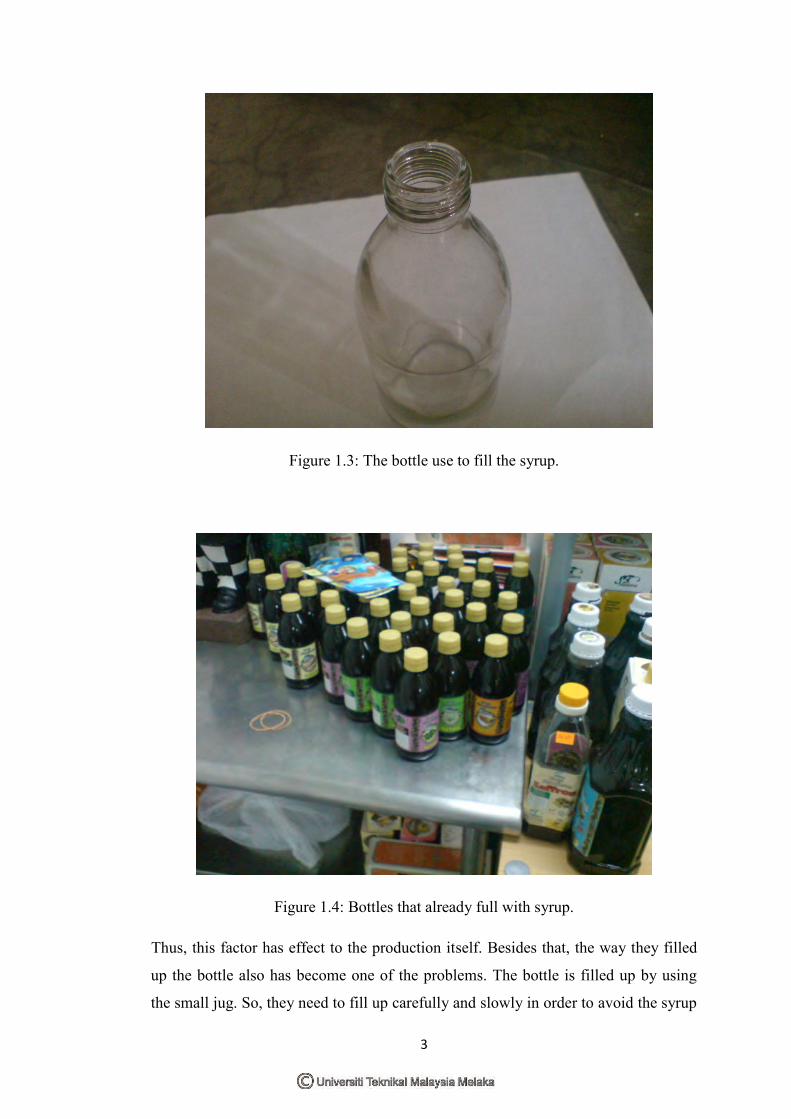
Figure 1.3: The bottle use to fill the syrup.
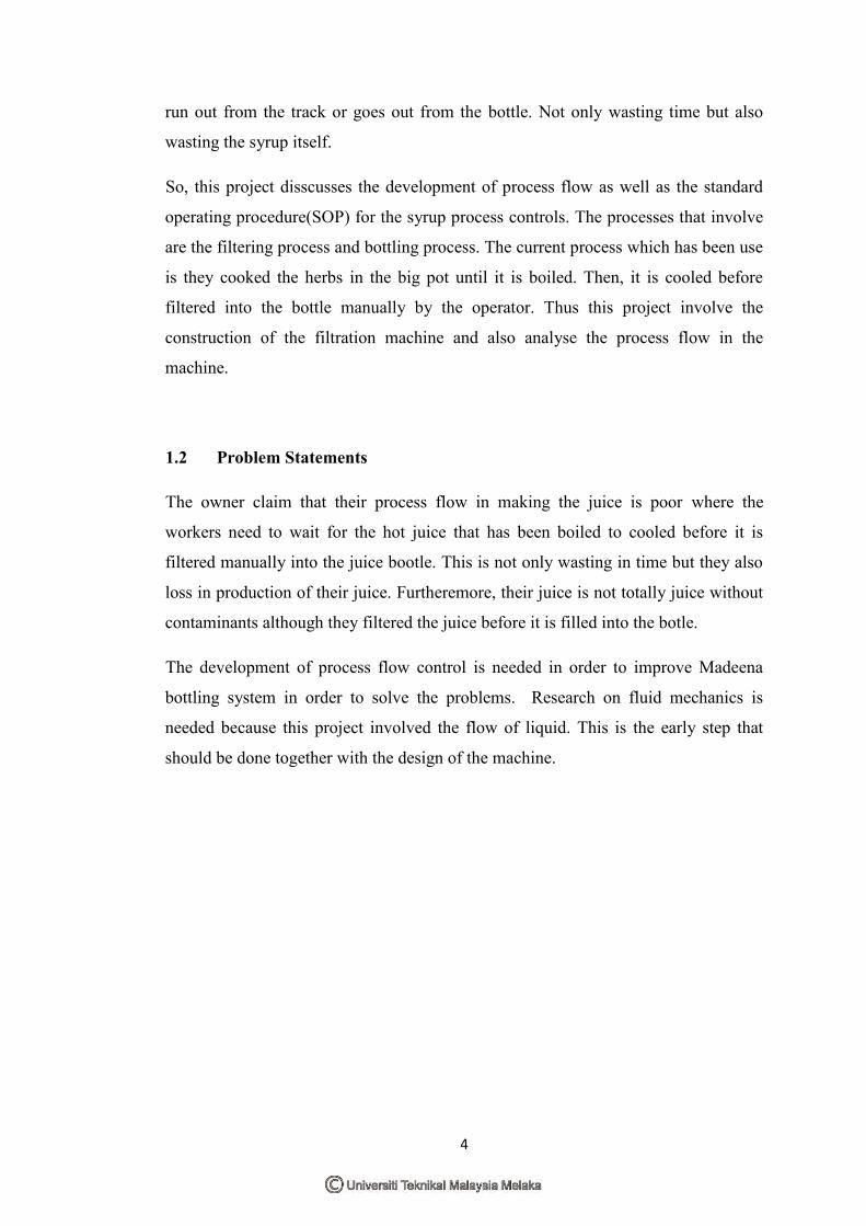
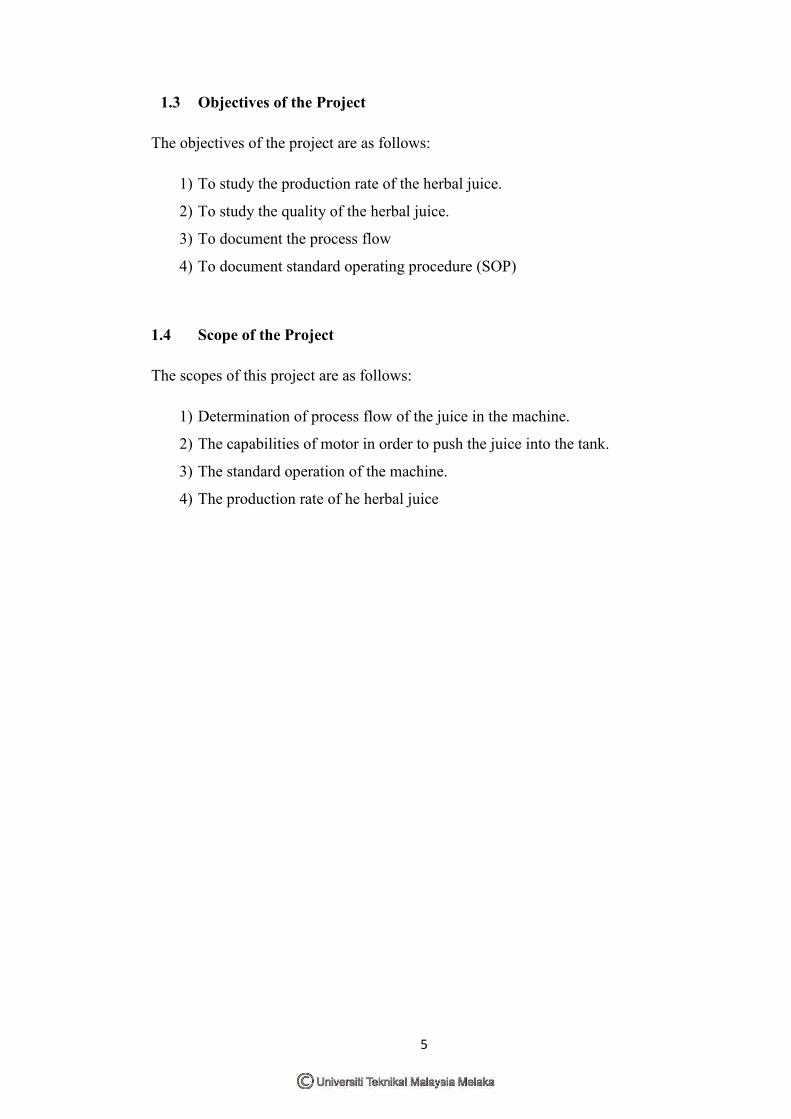
Figure 1.4: Bottles that already full with syrup.
Thus, this factor has effect to the production itself. Besides that, the way they filled
up the bottle also has become one of the problems. The bottle is filled up by using
the small jug. So, they need to fill up carefully and slowly in order to avoid the syrup
4
run out from the track or goes out from the bottle. Not only wasting time but also
wasting the syrup itself.
So, this project disscusses the development of process flow as well as the standard
operating procedure(SOP) for the syrup process controls. The processes that involve
are the filtering process and bottling process. The current process which has been use
is they cooked the herbs in the big pot until it is boiled. Then, it is cooled before
filtered into the bottle manually by the operator. Thus this project involve the
construction of the filtration machine and also analyse the process flow in the
machine.
1.2 Problem Statements
The owner claim that their process flow in making the juice is poor where the
workers need to wait for the hot juice that has been boiled to cooled before it is
filtered manually into the juice bootle. This is not only wasting in time but they also
loss in production of their juice. Furtheremore, their juice is not totally juice without
contaminants although they filtered the juice before it is filled into the botle.
The development of process flow control is needed in order to improve Madeena
bottling system in order to solve the problems. Research on fluid mechanics is
needed because this project involved the flow of liquid. This is the early step that
should be done together with the design of the machine.
5
1.3 Objectives of the Project
The objectives of the project are as follows:
1) To study the production rate of the herbal juice.
2) To study the quality of the herbal juice.
3) To document the process flow
4) To document standard operating procedure (SOP)
1.4 Scope of the Project
The scopes of this project are as follows:
1) Determination of process flow of the juice in the machine.
2) The capabilities of motor in order to push the juice into the tank.
3) The standard operation of the machine.
4) The production rate of he herbal juice
6
CHAPTER 2LITERATURE REVIEW
This chapter discusses about the introduction to fluid mechanic, definition of fluid,
and Bernoulli’s Principle. Besides, this chapter also discusses about the basic
equation in analyzing the problem of fluid mechanics problem, pump, filtration of
liquid, filtration methodes, types of filtration and the research that have been done
about filtration of syrup liquid. Futhermore, since this project is build a filtration
machine, the informations about Standard Operating Procedure(SOP) is also
included in this chapter.
2.1 Fluid Mechanic
2.1.1 Introduction to Fluid Mechanic
The study at rest or in motion is called fluid mechanics. This area of physics
is divided into fluid statics, the study of the behavior of stationary fluids, and fluid
dynamics, the study of the behavior of moving, or flowing, fluids. Fluid dynamics is
further divided into hydrodynamics, or the study of water flow, and aerodynamics,
the study of airflow.
The application of fluid mechanics is many such as the design of canal, levee,
and dam systems; the design of pumps, compressors, and piping and ducting used in
water and air conditioning systems of homes and businesses, as well as the piping
systems needed in chemical plants; the aerodynamics of automobiles and supersonic
airplanes; and development of many different flow measurement devices such as gas
pump meters. It is truly a “high-tech” or “hot discipline, and many exciting areas
have develop in last quater century although these are still important areas(witness,
7
for example, the current emphasis on automobile streamlining and the levee failure in
New Orleans). The scope of fluid mechanics is large such an example is:
Environmental and Energy Issues
- Containing oil slicks
- Large scale wind turbines
- Energy generation from ocean waves
- The aerodynamics of large buildings
- Fluid mechanics of the atmosphere and ocean
- Phenomena such as tornadoes, hurricanes and tsunamis
Biomechanics
- Artifial hearts and valve
- Understanding of fluid mechanics of blood
- Synovial fluid in joints
- Rrespirotory system
- Circulatory system
- Urinary System
Sport
- Design of bicycle and bicycle helmet
- Skis
- Sprinting and swimming clothing
- Aerodynamics of the golf, tennis and soccer ball.
Smart Fluid
- In automobile suspension systems to optimize motion under all terrain
conditions
- Millitary uniform containing a fluid layer is “thin” until combat, where it can
stiffenend to give the soldier strenght and protection
- Fluid lenses with humanlike properties for use in cameras and all cell phones
Microfluids
- For extremely precise administration of medications

8
2.1.2 Definition of fluid
Fluid is used as opposed to the solid where it tend to flow when we interact with
them such as we stiring our morning coffee. But for the solid, it tend to deform or
bend such as when we type on keyboard, the spring under the button compress. So,
as what has been conclude that, fluid is a substance that deforms continously under
the application of shear (tangential) stresses no matter how small the shear stress may
be. The other definition of the fluid is a substance that cannot sustain a shear stress at
rest. This is because, the fluid motion continous under the application of shear stress.
So, only two phases or form that fluid can take that are liquid and gases. The
difference between solid and fluid behavior in Figure 1 below.
Figure 2.1: Difference in behavior of solid and a fluid due to shear force.
When, a specimen or substance is added between two plates ( Figure 2.1a ) and then
a shearing force is applied to the plate, the substance will initially deform. But, the
solid will then be at rest where the force is not beyond the elastic limit and the fluid
will still continue to deform as long as the force is appllied. The rate of the
deformation of the fluids depends on the fluid’s viscosity, µ. The solid is considered
as being elastic and fluid as being viscous.
2.1.3 Bernoulli’s Principle
Long year ago, there are two people tha known as Archimedes and Pascal. They are
contributed greatly to what became known as fluid statics, but the father of fluid
mechanics, as a larger realm of study, was the Swiss mathematician and physicist
Time