universiti teknikal malaysia melaka -...
TRANSCRIPT
1
UNIVERSITI TEKNIKAL MALAYSIA MELAKA ����
Electrode Tool Wear Analysis under Various
Cutting Parameters in the Die Sinking Electrical Discharge Machine (EDM)
Thesis submitted in accordance with the requirements of the
Universiti Teknikal Malaysia Melaka for the Degree of
Bachelor of Manufacturing Engineering (Manufacturing Process)
�By
Zariyanti Bte Paijoo
����Faculty of Manufacturing Engineering
April 2007
2
�
UTeM Library
������
�����
����������
������������������������������������������������������� ������������������������������������������
������������!"#$%�
������������������������������������������������
&����&���������'�������������� ����������������������%�
� �(��() ( �*�(����%�
����������� +��(&,�-.��������/���,�01"..,��������,�/&�&�2��������+�!3�����$..#�
�
���������&���+�
� �(��() ( �*�(4���%�
�5& ������+�������
������+�66666666666666666666666�
�7�����������������������������������������8����&��&��9����:�����������������;���� �����������,��������������������� �����������;��������������������� �����������,�������� &����*�&����������������� *��%2�77�/�����������������������������,��������� ���������������� ���� �������������'&���������������������������������������������������������� &������������ ���������������������������������������2�
�� ��� � ��� � �� �� ���� �����
���������������� ������� ����
/����+�����
������*�() /�(+�����$..<�=�����$..#������ _____________________________________________________________________ �������������������������� *��'�������'�&��&��9����:��%���������� ������*�� ������������>�������������������������������� ����%��������������?������������������ ������������+��
!2 ��������������������������>�������������������������������2�$2 *�� ������������>�����������������������������������������������������������
������������� ���������������2�<2 *�� ������������������������������������������������������������ ����������
����������������� ���������������2�12 77�������������� �%�
�
������� ����������� �
�
���;��&����&&��@ ������������������A���&���5�������*��������������������������������;���;������;��������;����� ���%�
3
ELECTRODE TOOL WEAR ANALYSIS UNDER VARIOUS CUTTING
PARAMETERS IN THE DIE SINKING ELECTRICAL DISCHARGE
MACHINE (EDM)
ZARIYANTI BTE PAIJOO
UNIVERSITI TEKNIKAL MALAYSIA, MELAKA
4
APPROVAL
This thesis submitted to the senate of UTeM and has been accepted as partial
fulfillment of the requirements for the degree of Bachelor of Manufacturing Engineering
(Manufacturing Process). The members of the supervisory committee are as follow:
………………………………………….
Main Supervisor
(Official Stamp & Date)
5
DECLARATION��
�
�
I hereby, declare this thesis entitled “Electrode Tool Wear Analysis under Various
Cutting Parameters in the Die Sinking Electrical Discharge Machine (EDM)” is the
results of my own research except as cited in the reference.
Signature : …………………………
Author’s Name : ZARIYANTI BT PAIJOO
Date : 16 MEI 2007
6
ABSTRACT
The EDM removes workpiece by an electrical spark erosion process. The shape of the
electrode determines the shape of the workpiece owing to the electrode being sunk into
the workpiece. Electrode wear is a serius drawback in EDM process, this is because each
spark discharge removes material not only from the workpiece but also from the
electrode. Therefore, proper selection of the machining parameters can result in better
machining performance, for example EWR, MRR and Surface Roughness. The rate of
electrode tool wear depends on a number of factors associated with the EDM process
such as Current, Voltage and Jump Speed. This thesis investigate the EWR and
characteristic of electrode wear under several machining parameters (current, voltage
and jump speed) of copper electrode. The DOE were used to find the significant
machining parameter that most influence the EWR. Experimental result indicates that IP
(Current) and V (Voltage) were the most significant factor that effect the EWR.
7
ABSTRAK
EDM adalah pemesinan nyahcas electrik yang membuang permukaan benda kerja
melalui proses hakisan oleh percikkan api. Bentuk elektrod akan menentukan bentuk
benda kerja disebabkan oleh electrod yang diukir ke dalam benda kerja. Kehausan
electrod adalah salah satu kelemahan di dalam proses pemesinan EDM, ini kerana
setiap percikkan api akan membuang bahan bukan sahaja dari benda kerja tetapi juga
daripada elektrod. Oleh itu, pemilihan parameter yang sesuai dapat menghasilkan
prestasi pemesinan yang baik, sebagai contoh kadar kehausan elektrod, kadar
pemindahan bahan dan juga kekasaran permukaan. Kadar kehausan elektrod bergantung
kepada beberapa faktor penting yang berhubung dengan proses EDM seperti arus
elektrik, voltan dan lompatan kelajuan. Kajian ini tertumpu kepada kadar kehausan
elektrod dan ciri-ciri kehausan yang terdapat pada elektrod di bawah beberapa parameter
pemesinan iaitu arus elektrik, voltan dan lompatan kelajuan .Analisis daripada
eksperimen ini akan ditentukan dengan menggunakan kaedah DOE untuk mendapatkan
parameter pemesinan yang mana ia boleh mempengaruhi kadar kehausan elektrod.
Keputusan daripada eksperimen akan menunjukkan bahawa arus elektrik dan voltan
memainkan peranan penting serta memberi kesan terhadap kehausan elektrod.
8
DEDICATION
Especially dedicated to my parent, brothers and sisters
9
ACKNOWLEDGEMENTS
A special thanks to my Supervisor, Mr. Raja Izamshah B Raja Abdullah for his
supervision in doing this project. I greatly appreciate his consistent encouragement,
advice and invaluable guidance throughout the project.
I wish to extend my special appreciation to Mr. Hadzley B. Abu Bakar, Mr.
Sivarao, Mr. Akramin B. Mohamad and all technicians for their patience, support and
comment.
I would like to express my deepest appreciation and gratitude to my family
members for their love, sacrifice, motivation and support in completing this project. Last
but not least, I would like to thanks those who have contributed directly or indirectly
towards the success of this project.
10
TABLE OF CONTENTS
Abstract…………………………………………………………..……………………….i
Dedication………………………………………………………………………………..ii
Acknowledgement……………………………………………………………………….iii
Table of Contents………………………………………………………………………..iv
List of Figures……………………………...…………………………………………...vii
List of Tables…………………………………………………………………………….ix
Sign and Symbols………………………………………………………………………..xi
1. INTRODUCTION
1.1 Introduction………………………………………………………………………..1
1.2 Background of the problem………………………………………………………..2
1.3 Objectives………………………………………………………………………….2
1.4 Scopes……………………………………………………………………………...3
1.5 Important of the Study……………………………………………………………..3
1.6 Expected result…………………………………………………………………….3
2. LITERATURES REVIEW
2.1 Electrical Discharge Machining (EDM)………………………………………...…4
2.2 Die-Sinking EDM………………………………………………………………….6
2.3 Principles of Die Sinking EDM……………………………………………………7
2.4 Flushing……………………………………………………………………………8
2.5 Dielectric Fluid…………………………………………………………………...12
2.6 The Servo Mechanism……………………………………………………………13
2.7 Material Removal Mechanism…………………………………………………...14
2.8 Material Removal Rates………………………………………………………….15
2.9 Electrodes………………………………………………………………………...16
2.9.1 Graphite…………………………………………………………………….18
11
2.9.2 Copper……………………………………………………………………...21
2.10 Material of Workpiece…………………………………………………………..22
2.10.1 Stainless Steel 304……………………………………………………….22
2.10.2 Mild Steel……………………………………………………………….24
2.10.2.1 Types of Carbon Steel…………………………………………25
2.10.2.2 Metallurgy……………………………………………………..25
2.11 Dimensional Accuracy………………………………………………………….27
2.12 Parameter Selection in Electrode Tool Wear EDM…………………………….27
2.12.1 Current…………………………………………………………………...28
2.12.2 Voltage…………………………………………………………………..29
2.12.3 Spark Gap………………………………………………………………..29
2.12.4 Jump Speed………………………………………………………………30
2.13 Electrode Tool Wear…………………………………………………………….31
2.13.1 Electrode Wear (Graphite and Copper)………………………………….33
2.13.2 Type of Tool Wear………………………………………………………35
2.13.3 Electrode Wear Compensation…………………………………………..36
2.14 Resolution (Image Analysis Microscope)………………………………………37
2.15 Design of Experiments (DOE)………………………………………………….37
2.15.1 Analysis of Variance (ANOVA)………………………………………...39
2.15.2 The 2k Factorial Design………………………………………………….39
2.16 Conclusion of Literature Review………………………………………………..39
3. METHODOLOGY
3.1 Introduction………………………………………………………………………41
3.2 The Design of Experiment Process (DOE)………………………………………42
3.2.1 Objective the Experiment…………………………………………………..42
3.2.2 Identification of the Control Factors and Their Level……………………...42
3.2.3 Identify Suitable Noise Factor/Response…………………………………..43
3.2.4 Select the Appropriate Orthogonal Array (OA)……………………………43
3.2.4.1 Orthogonal Array Table……………………………………………45
12
3.2.5 Preparation of the Experiment Conducted…………………………………46
3.2.5.1 Parameter Setting…………………………………………………..47
3.2.5.2 Specimen Preparation………………………………………………48
3.2.5.3 Electrode Copper…………………………………………………...48
3.2.5.4 Workpiece Preparation……………………………………………. 49
3.2.5.5 Conduct the Experiment..…………………………………………..49
3.2.5.6 Testing ……………………………………………………………..51
3.2.5.7 Image Analysis Microscope………………………………………..53
3.2.6 Analyzed and Interpreted Results of Experiment Trials……………………54
3.2.7 Conclusion and Recommendation…………………………………………..55
3.3 Flow Chart……………………………………………………………………….55
4. EXPERIMENT PROCEDURE AND SETUP
4.1 Preparation Procedure……………………………………………………………57
4.2 Experiment, Equipment and Procedure…………………………………………..57
4.3 Setup Procedure…………………………………………………………………..58
4.4 Machining Parameter……………………………………………………………..59
5. RESULT AND DISCUSSIONS
5.1 Result and Discussion…………………………………………………………….61
5.2 Orthogonal Array Experiment……………………………………………………62
5.3 Normal Probability of Effects Analysis………………………………………….64
5.4 Pareto Chart of Effects Analysis…………………………………………………65
5.5 Interaction Plot (data mean) for Electrode Wear………………………………...66
5.6 Main Effect Plot (data mean) for Electrode Wear……………………………… 67
5.7 Pareto Chart of the Standardized Effect………………………………………….68
5.8 Cube Plot (data mean) for Electrode Wear……………………………………….69
5.9 Balanced ANOVA………………………………………………………………..70
5.9.1 Full Factorial Design………………………………………………………..71
5.9.2 ANOVA: EW versus IP, V………………………………………………….71
13
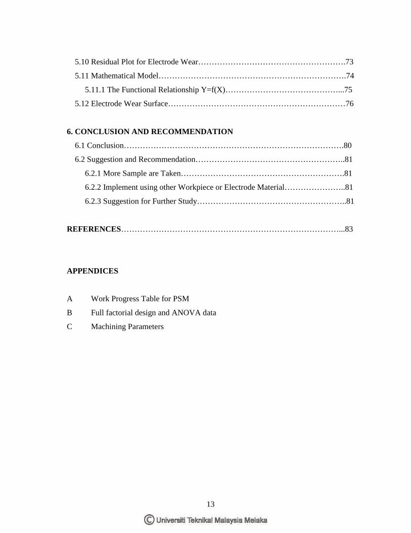
5.10 Residual Plot for Electrode Wear……………………………………………….73
5.11 Mathematical Model…………………………………………………………….74
5.11.1 The Functional Relationship Y=f(X)……………………………………...75
5.12 Electrode Wear Surface…………………………………………………………76
6. CONCLUSION AND RECOMMENDATION
6.1 Conclusion……………………………………………………………………….80
6.2 Suggestion and Recommendation………………………………………………..81
6.2.1 More Sample are Taken…………………………………………………….81
6.2.2 Implement using other Workpiece or Electrode Material…………………..81
6.2.3 Suggestion for Further Study………………………………………………..81
REFERENCES………………………………………………………………………...83
APPENDICES
A Work Progress Table for PSM
B Full factorial design and ANOVA data
C Machining Parameters
14
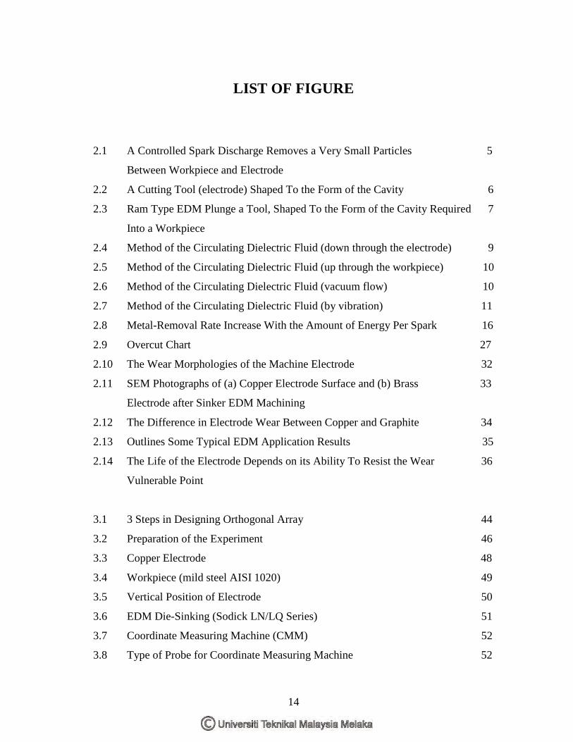
LIST OF FIGURE
2.1 A Controlled Spark Discharge Removes a Very Small Particles 5
Between Workpiece and Electrode
2.2 A Cutting Tool (electrode) Shaped To the Form of the Cavity 6
2.3 Ram Type EDM Plunge a Tool, Shaped To the Form of the Cavity Required 7
Into a Workpiece
2.4 Method of the Circulating Dielectric Fluid (down through the electrode) 9
2.5 Method of the Circulating Dielectric Fluid (up through the workpiece) 10
2.6 Method of the Circulating Dielectric Fluid (vacuum flow) 10
2.7 Method of the Circulating Dielectric Fluid (by vibration) 11
2.8 Metal-Removal Rate Increase With the Amount of Energy Per Spark 16
2.9 Overcut Chart 27
2.10 The Wear Morphologies of the Machine Electrode 32
2.11 SEM Photographs of (a) Copper Electrode Surface and (b) Brass 33
Electrode after Sinker EDM Machining
2.12 The Difference in Electrode Wear Between Copper and Graphite 34
2.13 Outlines Some Typical EDM Application Results 35
2.14 The Life of the Electrode Depends on its Ability To Resist the Wear 36
Vulnerable Point
3.1 3 Steps in Designing Orthogonal Array 44
3.2 Preparation of the Experiment 46
3.3 Copper Electrode 48
3.4 Workpiece (mild steel AISI 1020) 49
3.5 Vertical Position of Electrode 50
3.6 EDM Die-Sinking (Sodick LN/LQ Series) 51
3.7 Coordinate Measuring Machine (CMM) 52
3.8 Type of Probe for Coordinate Measuring Machine 52
15
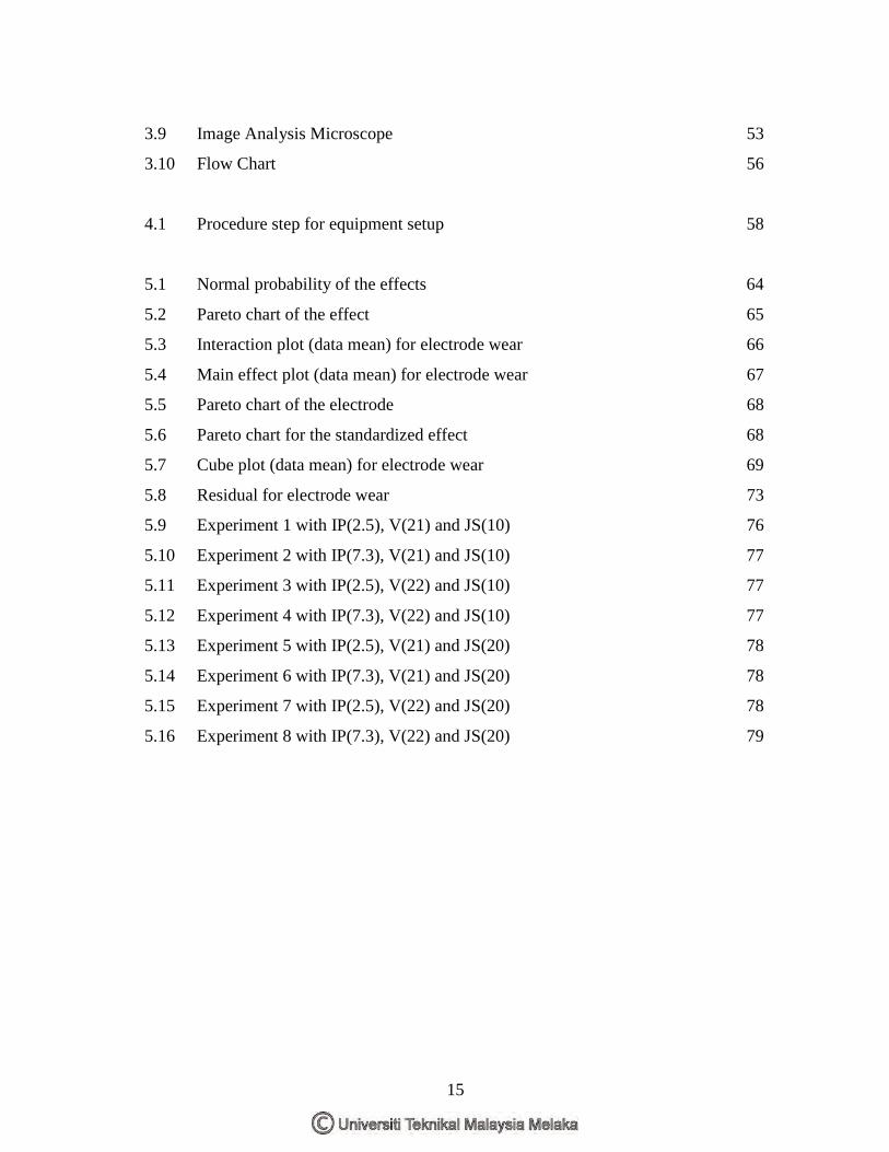
3.9 Image Analysis Microscope 53
3.10 Flow Chart 56
4.1 Procedure step for equipment setup 58
5.1 Normal probability of the effects 64
5.2 Pareto chart of the effect 65
5.3 Interaction plot (data mean) for electrode wear 66
5.4 Main effect plot (data mean) for electrode wear 67
5.5 Pareto chart of the electrode 68
5.6 Pareto chart for the standardized effect 68
5.7 Cube plot (data mean) for electrode wear 69
5.8 Residual for electrode wear 73
5.9 Experiment 1 with IP(2.5), V(21) and JS(10) 76
5.10 Experiment 2 with IP(7.3), V(21) and JS(10) 77
5.11 Experiment 3 with IP(2.5), V(22) and JS(10) 77
5.12 Experiment 4 with IP(7.3), V(22) and JS(10) 77
5.13 Experiment 5 with IP(2.5), V(21) and JS(20) 78
5.14 Experiment 6 with IP(7.3), V(21) and JS(20) 78
5.15 Experiment 7 with IP(2.5), V(22) and JS(20) 78
5.16 Experiment 8 with IP(7.3), V(22) and JS(20) 79
16
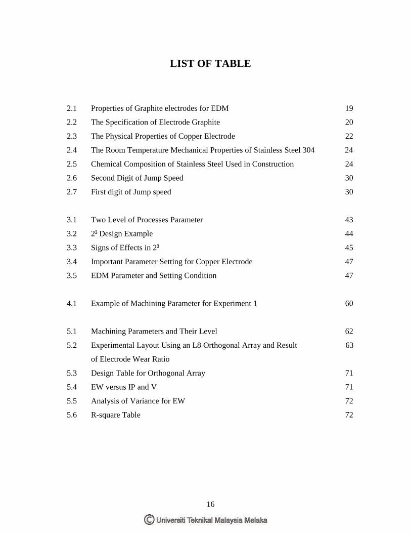
LIST OF TABLE
2.1 Properties of Graphite electrodes for EDM 19
2.2 The Specification of Electrode Graphite 20
2.3 The Physical Properties of Copper Electrode 22
2.4 The Room Temperature Mechanical Properties of Stainless Steel 304 24
2.5 Chemical Composition of Stainless Steel Used in Construction 24
2.6 Second Digit of Jump Speed 30
2.7 First digit of Jump speed 30
3.1 Two Level of Processes Parameter 43
3.2 2³ Design Example 44
3.3 Signs of Effects in 2³ 45
3.4 Important Parameter Setting for Copper Electrode 47
3.5 EDM Parameter and Setting Condition 47
4.1 Example of Machining Parameter for Experiment 1 60
5.1 Machining Parameters and Their Level 62
5.2 Experimental Layout Using an L8 Orthogonal Array and Result 63
of Electrode Wear Ratio
5.3 Design Table for Orthogonal Array 71
5.4 EW versus IP and V 71
5.5 Analysis of Variance for EW 72
5.6 R-square Table 72
17
LIST OF ABBREAVIATIONS, SYMBOLS AND SPECIALIZED NOMENCLATURE
A - Ampere
ANOVA - Analysis of variance
C - Carbon
CMM - Coordinate measuring machine
cm - Centimeter
DOE - Design of experiment
EW - Electrode Wear
Fe - Ferum
In - Inch
IP - Current
Js - Jump Speed
k - Factor
m - meter
Max - maximum
Min - minimum
Mn - Manganese
MPa - Mega pascal
MRR - material removal rate
min - minute
mm - millimeter
Ni - Nickle
OA - orthogonal array
Si - Silicon
SS - Sum of square
V - Volt
y - average
18
µm - micrometer
µin - microinch
µs - microsecond
� - ohm
µ�m - micro ohm meter
µ�/cm - micro ohm per centimeter
% - percent
ºC - degree celcius
- - low
+ - high
19
CHAPTER 1 INTRODUCTION
1.1 Introduction
EDM is a non-traditional machining process based on removing material from a
part by means of a series of repeated electrical discharges between a tool, called the
electrode and the part being machined in the presence of a dielectric fluid. At present
EDM is a widespread technique used in industry for high-precision machining of all
types of conductive materials such as: metals, metallic alloys, or even some ceramic
material of any hardness.
In the electrical discharge machining process, the shape of the electrode
determines the shape of the workpiece owing to the electrode being sunk into the
workpiece. However, electrode wear takes place during the electrical discharge
machining process. This is because each spark discharge removes material not only from
the workpiece but also from the electrode. Therefore, the study of electrode wear is
important to ensure the required dimensional accuracy and geometry of the workpiece
can be achieved.
The rate of electrode tool wear depends on a number of factors associated with
the EDM process such as current, voltage, jump speed, spark gap, polarity, electrode
material etc. The shapes of electrode tool wear can be characterized depending upon the
different machining parameters. This change in shapes of the tool electrode causes
defects in the workpiece which even more pronounced effects when it comes to
micromachining.
20
1.2 Background of the Problem
Electrical discharge machining (EDM) is rapidly becoming an important
manufacturing process for machining hard metals and alloy used in the aerospace, tool
and dies industries, manufacturing of mould and to produce the complex shape, which
required high precision and dimensional accuracy. As been stated, the shape of the
electrode will determine the shape of the workpiece or final product. Therefore, the
study of electrode wear is important to ensure the required dimensional accuracy and
geometry of the workpiece can be achieved.
Hence, this project will analyzed the characteristic and rate of electrode wear
under several parameters machining such as current, voltage and jump speed using
copper electrode.
1.3 Objectives
The purposes of this project are to:
i. To characterize the mechanism and morphology of tool wear according to
current, voltage and jump speed.
ii. To determine the electrode tool wear rate within different machining
parameter.
iii. To find the significant machining parameter that most influences the
electrode tool wear using orthogonal array approach.
21
1.4 Scopes
Several approaches are used throughout the project. According to the objectives,
the selected scopes of the project are:
i. To understand the EDM die-sinking machining process.
ii. To find the electrode tool wear rate of EDM die-sinking process.
iii. To analyze the type of electrode tool wear under various parameters
(current, voltage, jump speed) using Coordinate Measuring Machine
(CMM) and Image Analysis Microscope.
iv. To find the significant machining parameter that influences the rate of
tool wear using Orthogonal Array approach.
1.5 Important of the Study
The study of electrode wear is important to ensure the required dimensional
accuracy and geometry of the workpiece is meet. Beside that, the result from this study
will help to estimate the electrode reliability under various machining parameter.
1.6 Expected Result
Optimistically at the end of this project, the main effects of the EDM parameter
that influences the rate of electrode tool wear can be obtained.
22
CHAPTER 2 LITERATURE REVIEW
2.1 Electrical Discharge Machining (EDM)
Electrical discharge machining, commonly known as EDM, is a process that
remove metal by means of electrical spark erosion. Machining is performed by the
action to removes electrically conductive material by means of rapid, repetitive spark
discharges from a pulsating dc power supply with dielectric flowing between the work
piece and the tool. The shaped tool (electrode) is fed into the workpiece under servo
control. A spark discharge then breaks down the dielectric fluid. The frequency and
energy per spark are set and controlled with a dc power source. The servo control
maintains a constant gap between the tool and the workpiece while advancing the
electrode. The dielectric coil cools and flushes out the vaporized and condensed material
while reestablishing insulation in the gap. Figure 2.1 (circle figure) is shown the spark
discharge from a pulsating dc power supply with dielectric flowing between work piece
and tool (electrode). (Krar, 1996)
23
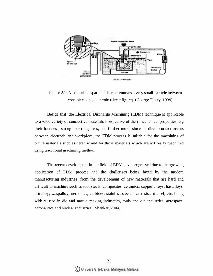
Figure 2.1: A controlled spark discharge removes a very small particle between
workpiece and electrode (circle figure). (George Tlusty, 1999)
Beside that, the Electrical Discharge Machining (EDM) technique is applicable
to a wide variety of conductive materials irrespective of their mechanical properties, e.g
their hardness, strength or toughness, etc. further more, since no direct contact occurs
between electrode and workpiece, the EDM process is suitable for the machining of
brittle materials such as ceramic and for those materials which are not really machined
using traditional machining method.
The recent development in the field of EDM have progressed due to the growing
application of EDM process and the challenges being faced by the modern
manufacturing industries, from the development of new materials that are hard and
difficult to machine such as tool steels, composites, ceramics, supper alloys, hastalloys,
nitralloy, waspalloy, nemonics, carbides, stainless steel, heat resistant steel, etc, being
widely used in die and mould making industries, tools and die industries, aerospace,
aeronautics and nuclear industries. (Shankar, 2004)
24
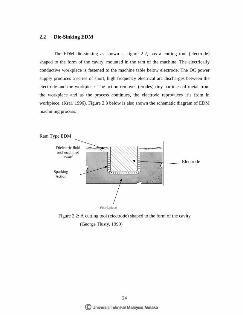
2.2 Die-Sinking EDM
The EDM die-sinking as shown at figure 2.2, has a cutting tool (electrode)
shaped to the form of the cavity, mounted in the ram of the machine. The electrically
conductive workpiece is fastened to the machine table below electrode. The DC power
supply produces a series of short, high frequency electrical arc discharges between the
electrode and the workpiece. The action removes (erodes) tiny particles of metal from
the workpiece and as the process continues, the electrode reproduces it’s from in
workpiece. (Krar, 1996). Figure 2.3 below is also shown the schematic diagram of EDM
machining process.
Ram Type EDM
Figure 2.2: A cutting tool (electrode) shaped to the form of the cavity
(George Tlusty, 1999)
Dielectric fluid and machined
swarf
Sparking Action
Workpiece
Electrode