kajian terhadap amalan terbaik dalam rekabentuk jalan...
TRANSCRIPT
KAJIAN TERHADAP AMALAN
TERBAIK DALAM
REKABENTUK JALAN DI
KAWASAN BERBUKIT Dibentang oleh;
Ir. Dr. Mohamad Nor bin Omar
Unit Geo-Environmental & Rekabentuk Asas
Cawangan Kejuruteraan Jalan & Geoteknik
ISI KANDUNGAN
PENGENALAN
OBJEKTIF KAJIAN
HASIL PENEMUAN KAJIAN
KAJIAN KES : KEGAGALAN LIMA (5) CERUN DI
JALAN PERSEKUTUAN FT185 IAITU LOJING –
GUA MUSANG
AMALAN TERBAIK DALAM REKABENTUK
JALAN DI KAWASAN BERBUKIT
KESIMPULAN
PENGENALAN
Kajian ini merupakan kajian susulan daripada
kajian awalan kejadian kegagalan cerun di Jalan
Persekutuan FT185 iaitu Lojing – Gua Musang
di mana telah diarahkan oleh Y.B. Menteri Kerja
Raya bagi menjalankan kajian menyeluruh
terhadap kegagalan cerun tersebut dan
seterusnya menambahbaik garis panduan
rekabentuk dan penyelenggaraan cerun sediada.
OBJEKTIF KAJIAN
Mengkaji punca-punca kegagalan cerun di jalan
kawasan berbukit di seluruh Malaysia.
Mengkaji amalan terbaik dalam merekabentuk
jalan di kawasan berbukit.
Menambahbaik garis panduan merekabentuk
cerun yang sediada
KAJIAN KES : KEGAGALAN LIMA (5) CERUN DI JALAN
PERSEKUTUAN FT185 IAITU LOJING – GUA
MUSANG
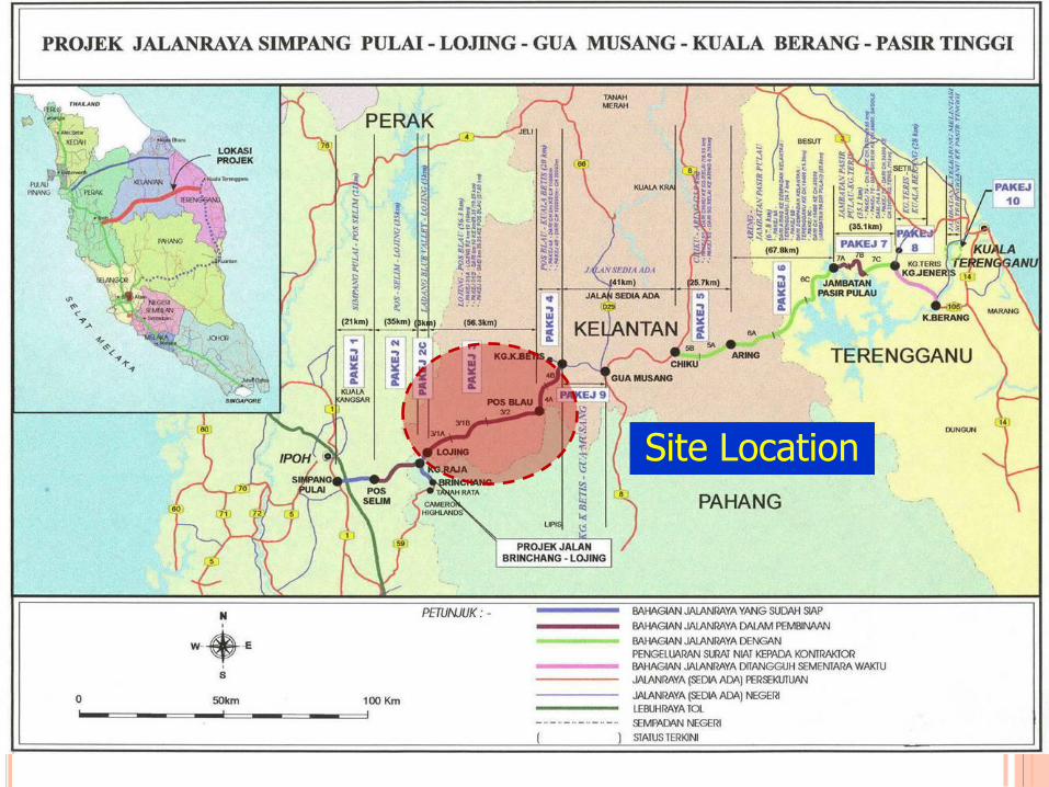
Site Location
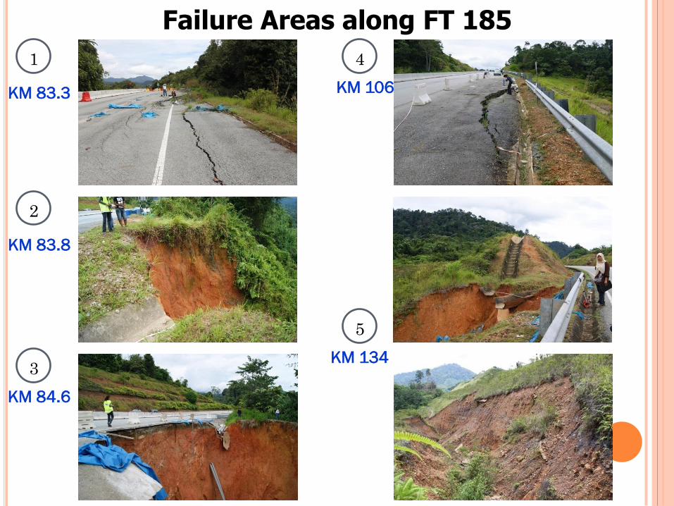
Failure Areas along FT 185
KM 83.3
KM 83.8
KM 84.6
KM 106
KM 134
1
2
3
4
5
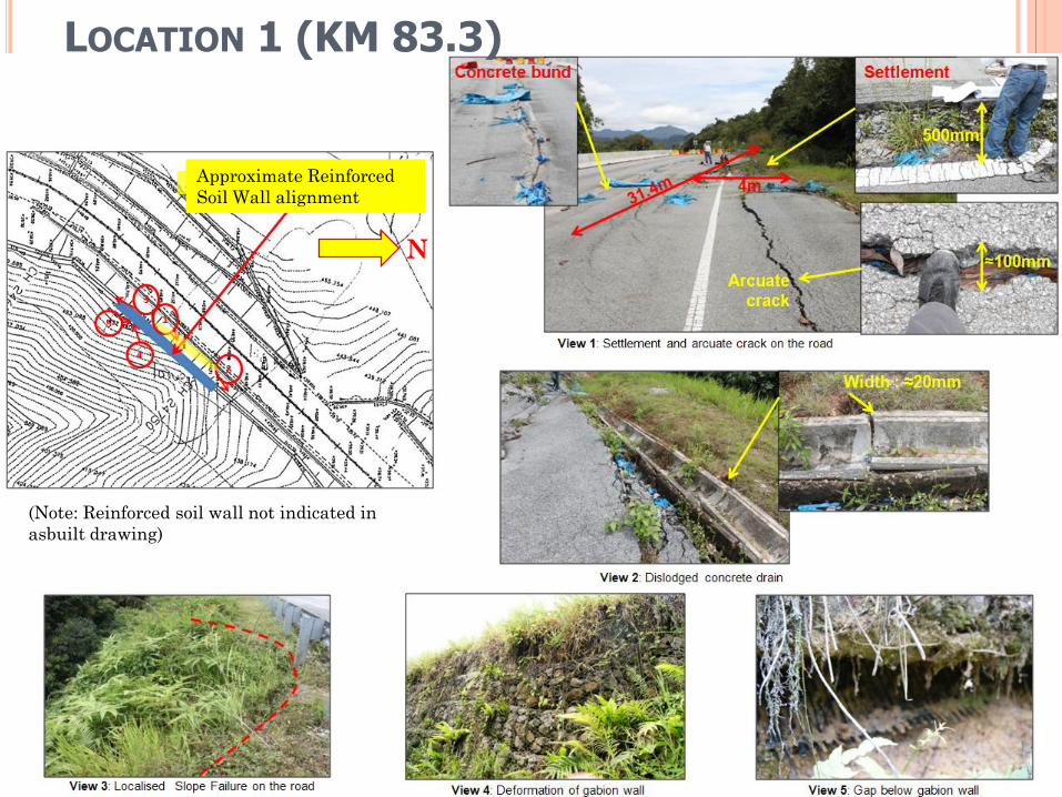
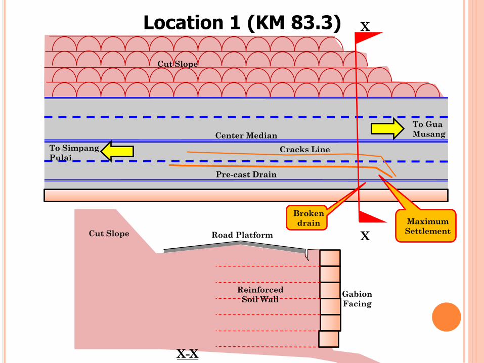
LOCATION 1 (KM 83.3)
(Note: Reinforced soil wall not indicated in
asbuilt drawing)
N
Approximate Reinforced
Soil Wall alignment
X
X
X-X
To Gua
Musang
To Simpang
Pulai
Road Platform
Reinforced
Soil Wall Gabion
Facing
Cracks Line
Maximum
Settlement
Center Median
Pre-cast Drain
Cut Slope
Cut Slope
Location 1 (KM 83.3)
Broken
drain
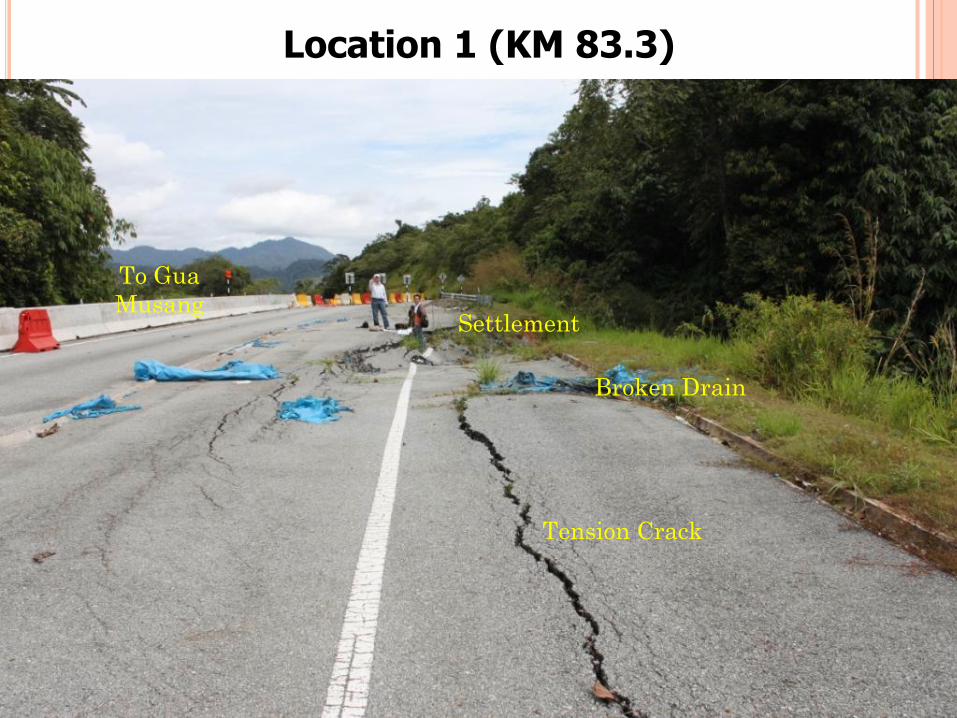
Location 1 (KM 83.3)
Tension Crack
Broken Drain
Settlement
To Gua
Musang
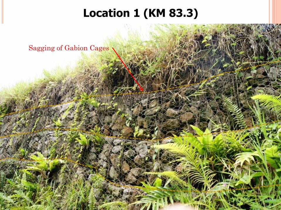
Location 1 (KM 83.3)
Sagging of Gabion Cages
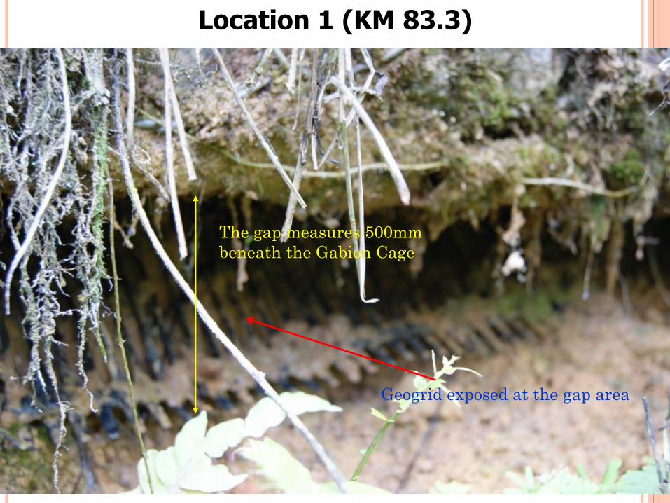
Location 1 (KM 83.3)
Geogrid exposed at the gap area
The gap measures 500mm
beneath the Gabion Cage
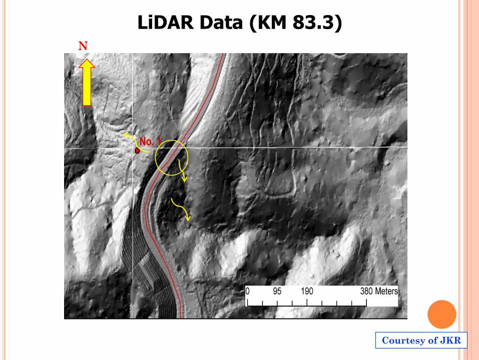
LiDAR Data (KM 83.3) N
Courtesy of JKR
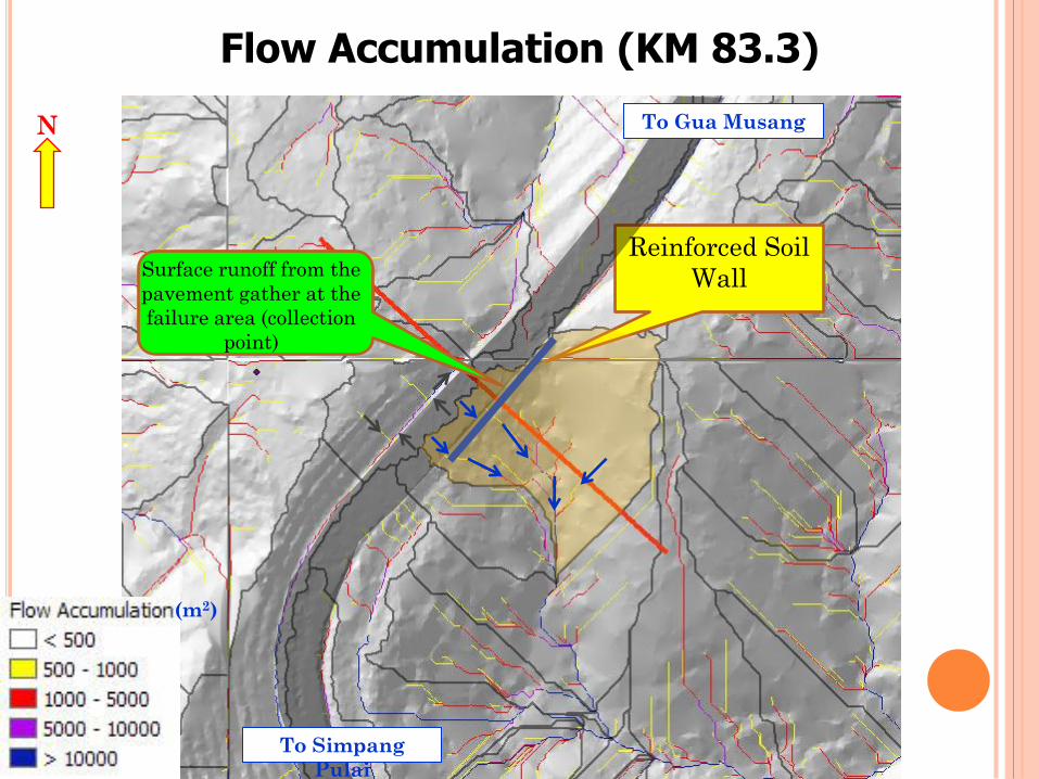
Flow Accumulation (KM 83.3)
N
Reinforced Soil
Wall
To Gua Musang
To Simpang
Pulai
Surface runoff from the
pavement gather at the
failure area (collection
point)
(m2)
Reinforced
Soil Wall
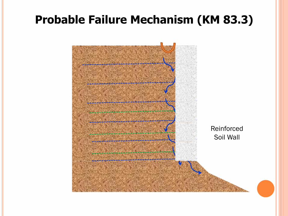
Probable Failure Mechanism (KM 83.3)
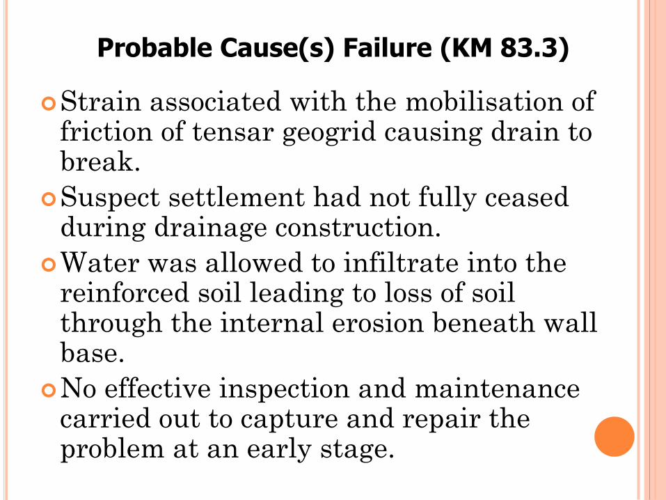
Strain associated with the mobilisation of friction of tensar geogrid causing drain to break.
Suspect settlement had not fully ceased during drainage construction.
Water was allowed to infiltrate into the reinforced soil leading to loss of soil through the internal erosion beneath wall base.
No effective inspection and maintenance carried out to capture and repair the problem at an early stage.
Probable Cause(s) Failure (KM 83.3)
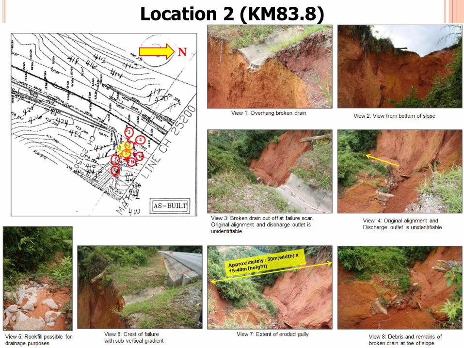
Location 2 (KM83.8)
N
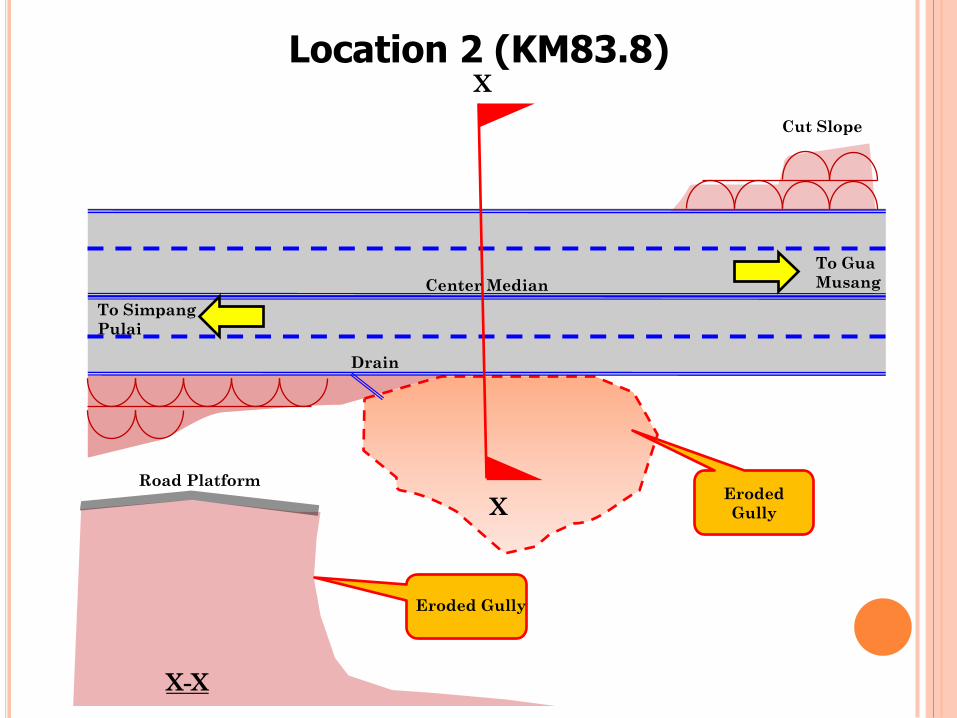
Location 2 (KM83.8)
X
To Gua
Musang
To Simpang
Pulai
Center Median
Drain
Cut Slope
X
X-X
Eroded Gully
Road Platform Eroded
Gully
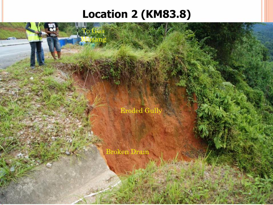
Location 2 (KM83.8)
Eroded Gully
Broken Drain
To Gua
Musang
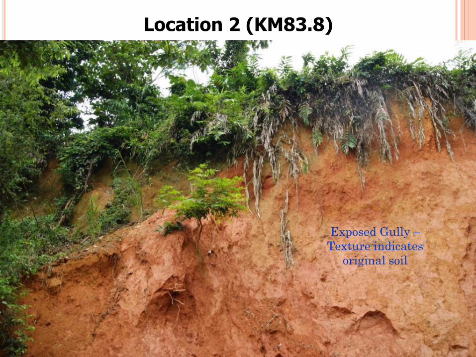
Location 2 (KM83.8)
Exposed Gully –
Texture indicates
original soil
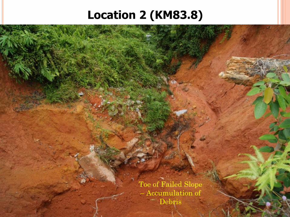
Location 2 (KM83.8)
Toe of Failed Slope
– Accumulation of
Debris
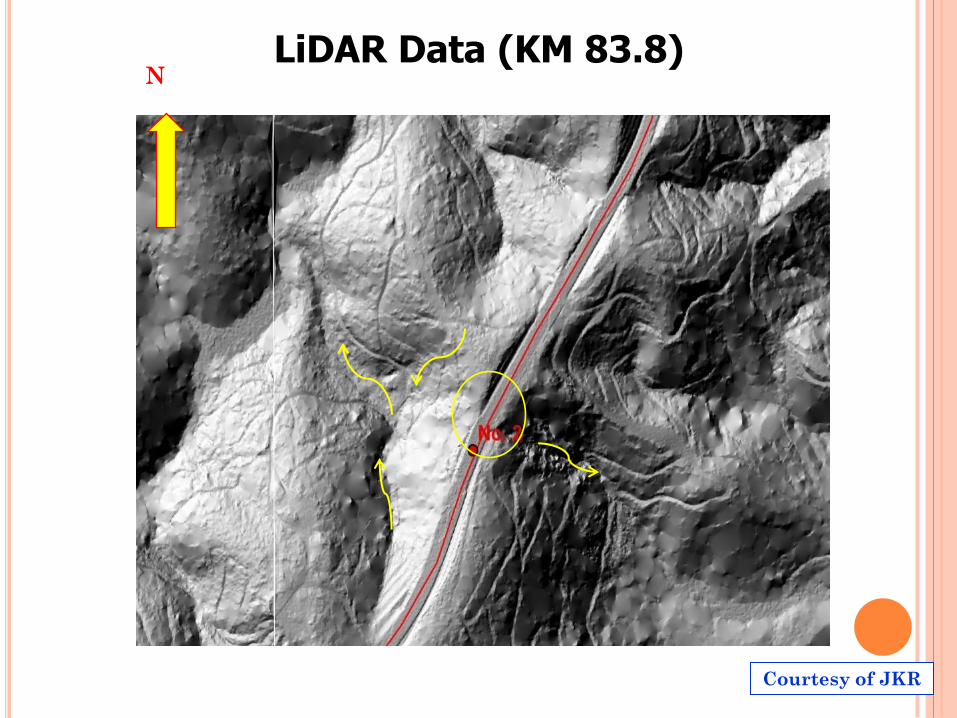
LiDAR Data (KM 83.8) N
Courtesy of JKR
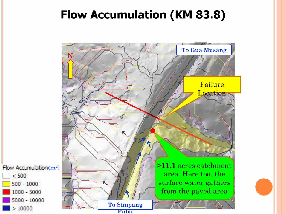
Flow Accumulation (KM 83.8)
Failure
Location
>11.1 acres catchment
area. Here too, the
surface water gathers
from the paved area
N To Gua Musang
To Simpang
Pulai
(m2)
Discharge outlet may not have been properly designed
and constructed which led to uncontrolled water flow
on the slope.
Erosion took place at toe / mid slope which was left
unattended for a long period of time.
No effective inspection and maintenance carried out to
capture and repair the problem at an early stage.
Probable Cause(s) Failure (KM 83.8)
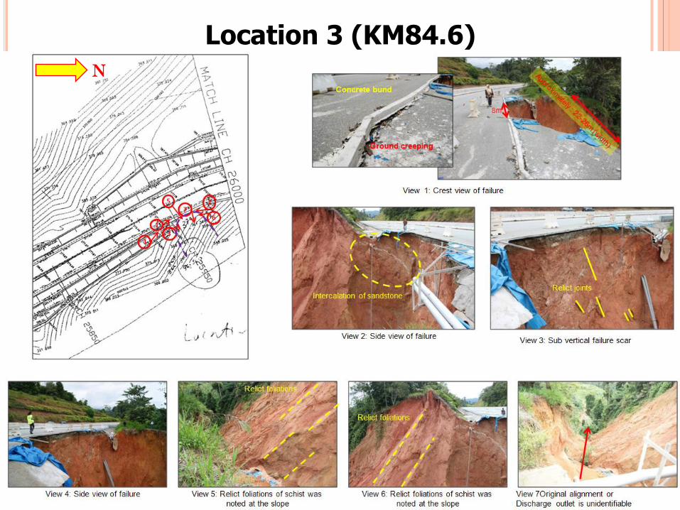
Location 3 (KM84.6)
N
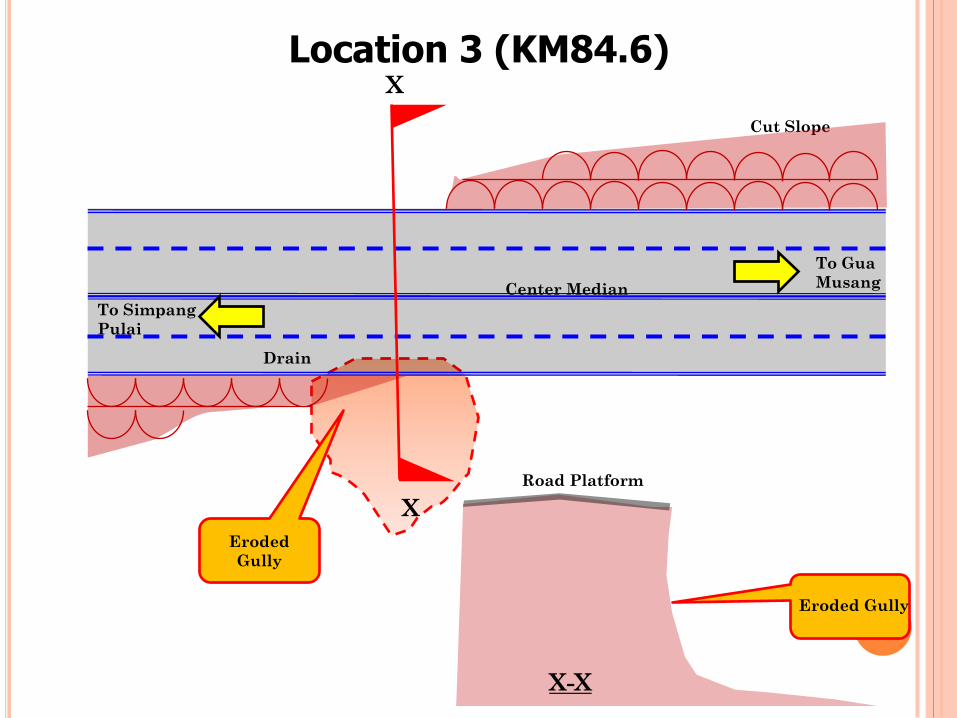
Location 3 (KM84.6)
X
To Gua
Musang
To Simpang
Pulai
Center Median
Drain
Cut Slope
X
X-X
Eroded Gully
Road Platform
Eroded
Gully
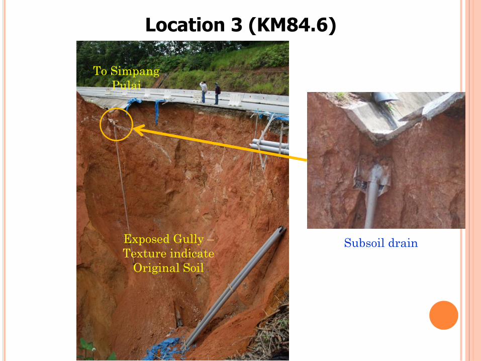
Location 3 (KM84.6)
Exposed Gully –
Texture indicate
Original Soil
To Simpang
Pulai
Subsoil drain
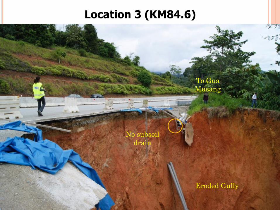
Location 3 (KM84.6)
Eroded Gully
To Gua
Musang
No subsoil
drain
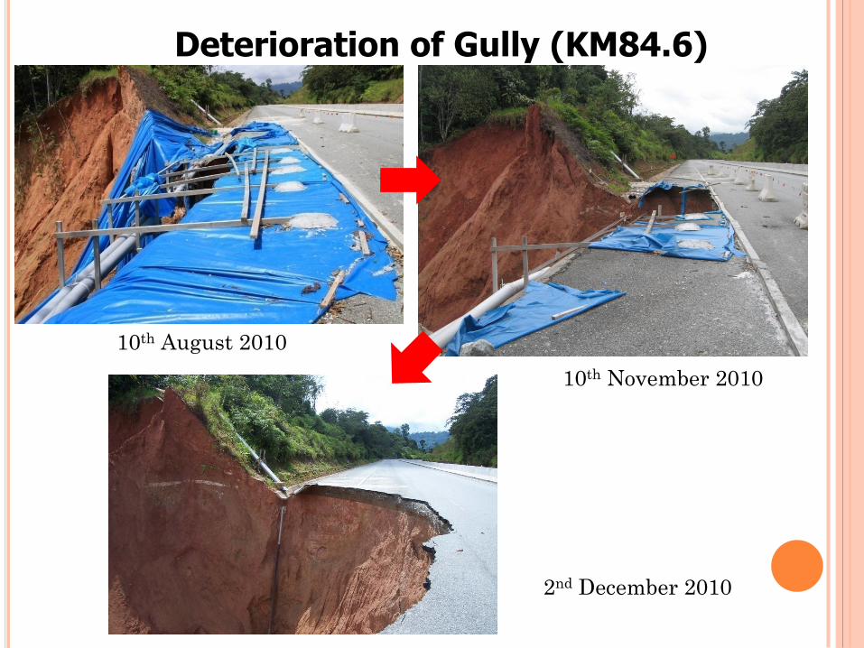
Deterioration of Gully (KM84.6)
10th August 2010
10th November 2010
2nd December 2010
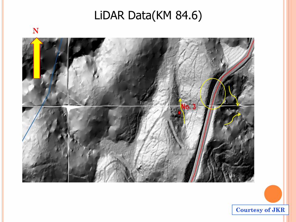
LiDAR Data(KM 84.6)
N
Courtesy of JKR
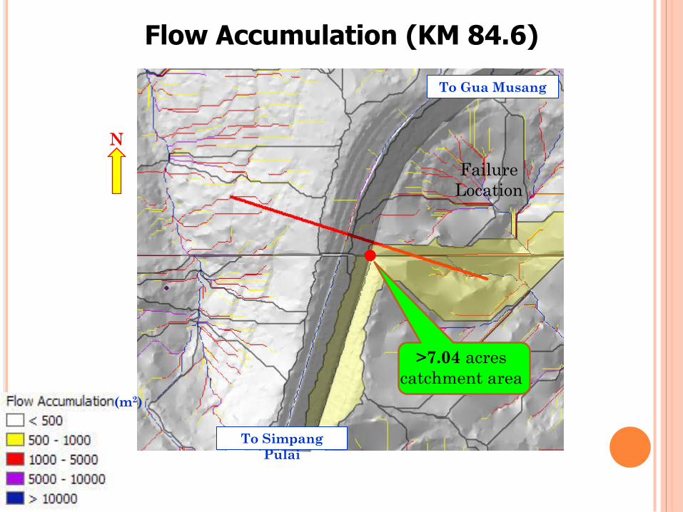
Flow Accumulation (KM 84.6)
N
To Gua Musang
>7.04 acres
catchment area
Failure
Location
(m2)
To Simpang
Pulai
Drainage system may not have been properly designed
and constructed
(Note: discharge outlet and details of subsoil drain are
not shown in as-built drawings)
Erosion took place (may have been triggered by poor
drainage design) and was left unattended for a long
period of time.
No effective inspection and maintenance carried out to
capture and repair the problem at an early stage.
Probable Cause(s) Failure (KM 84.6)
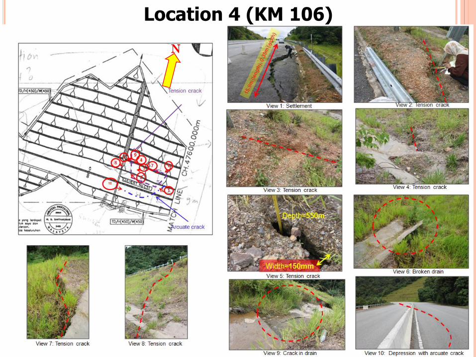
Location 4 (KM 106)
N
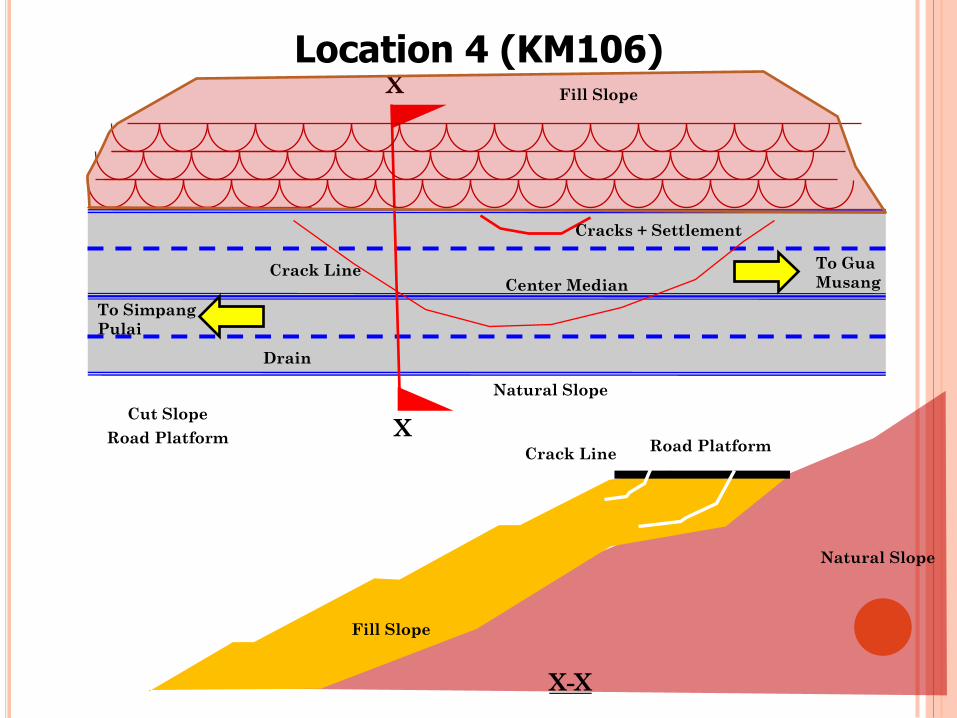
Location 4 (KM106)
X
To Gua
Musang
To Simpang
Pulai
Center Median
Drain
Cut Slope
X
X-X
Road Platform
Fill Slope
Natural Slope
Crack Line
Cracks + Settlement
Crack Line Road Platform
Fill Slope
Natural Slope
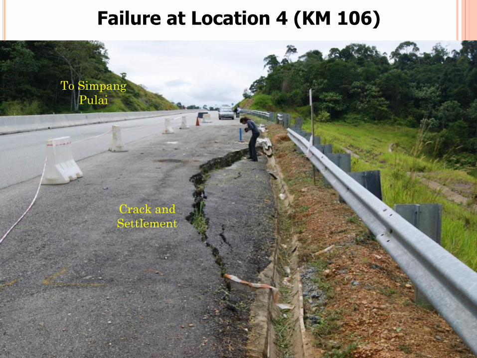
Failure at Location 4 (KM 106)
Crack and
Settlement
To Simpang
Pulai

Failure at Location 4 (KM 106)
Minor Depression and
Crack extends beyond
the road median
To Gua Musang
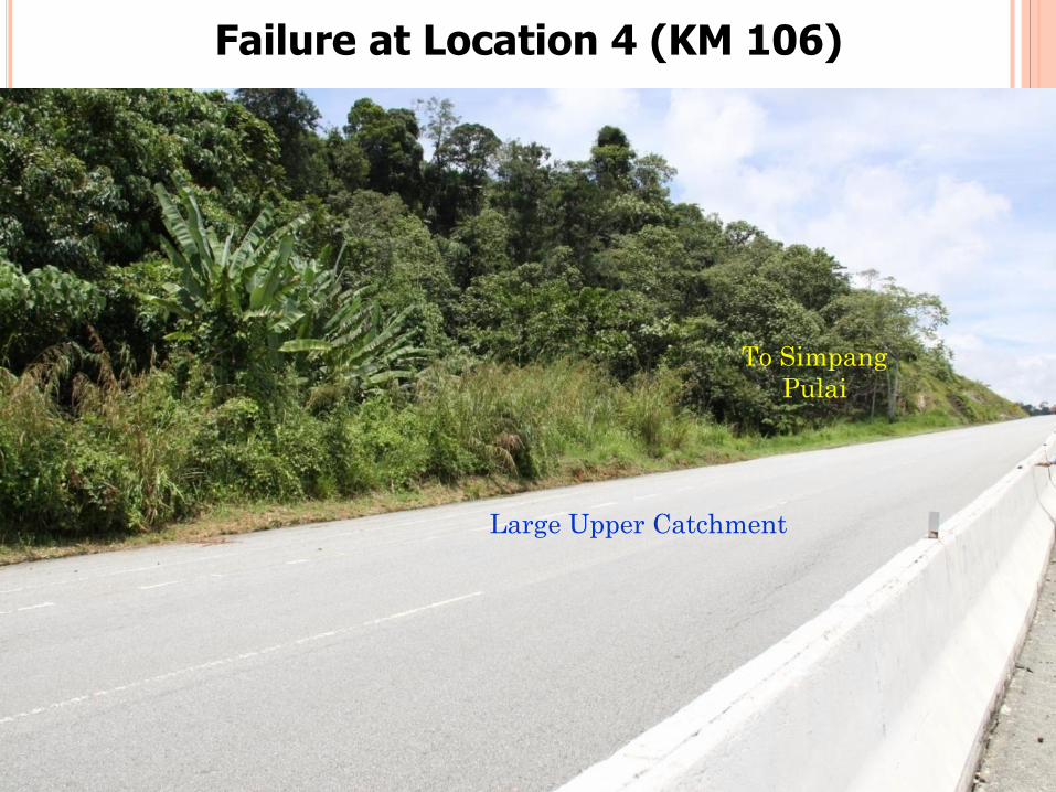
Failure at Location 4 (KM 106)
Large Upper Catchment
To Simpang
Pulai
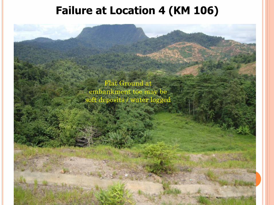
Failure at Location 4 (KM 106)
Flat Ground at
embankment toe may be
soft deposits / water logged
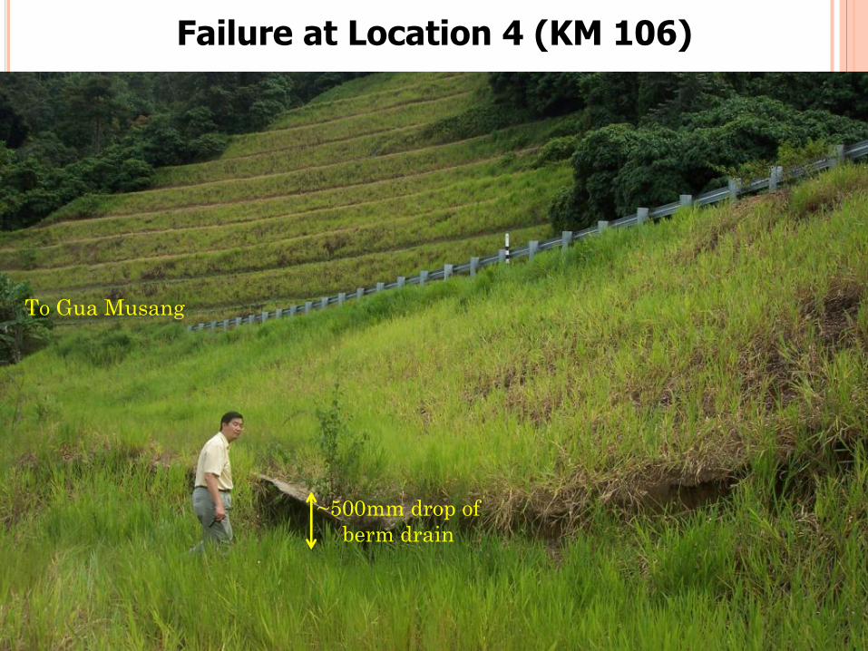
Failure at Location 4 (KM 106)
To Gua Musang
~500mm drop of
berm drain
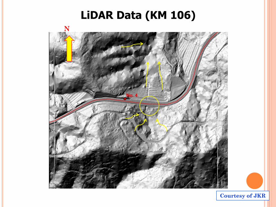
LiDAR Data (KM 106) N
Courtesy of JKR
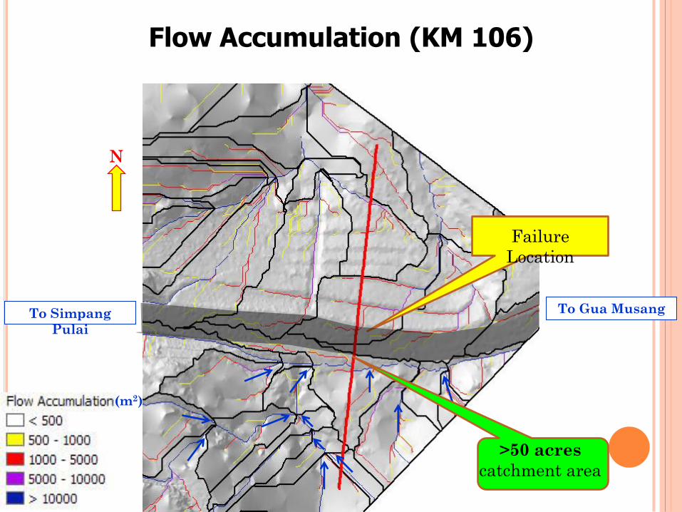
Flow Accumulation (KM 106)
N
Failure
Location
To Gua Musang To Simpang
Pulai
>50 acres
catchment area
(m2)
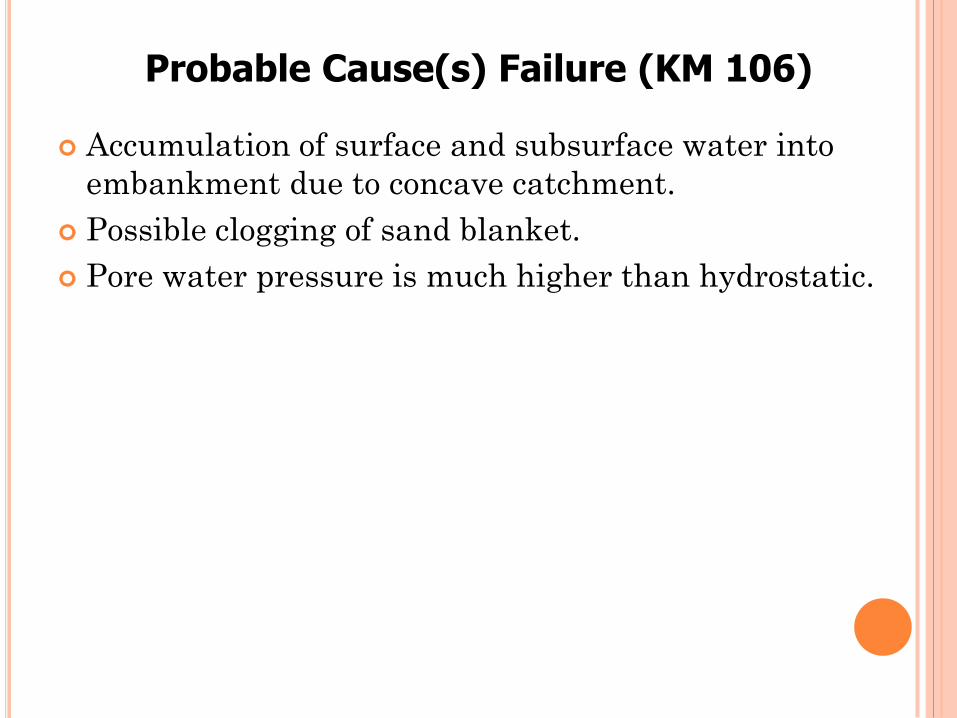
Accumulation of surface and subsurface water into
embankment due to concave catchment.
Possible clogging of sand blanket.
Pore water pressure is much higher than hydrostatic.
Probable Cause(s) Failure (KM 106)
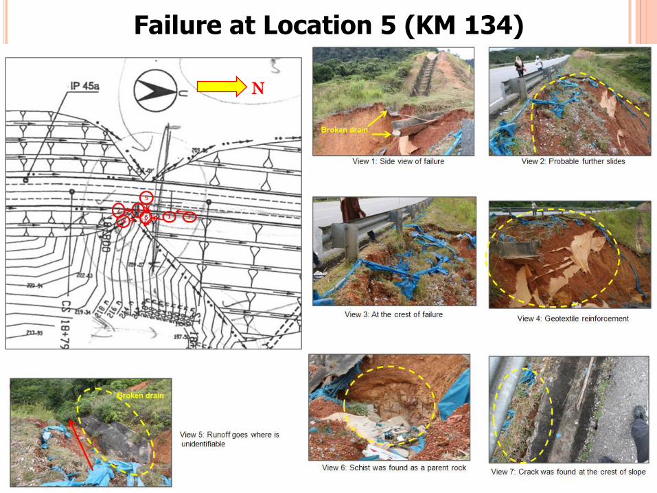
Failure at Location 5 (KM 134)
N
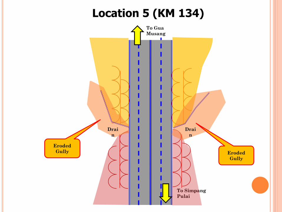
Location 5 (KM 134) To Gua
Musang
To Simpang
Pulai
Eroded
Gully Eroded
Gully
Drai
n
Drai
n

Failure at Location 5 (KM 134) - RHS
Broken Drain
To Simpang
Pulai
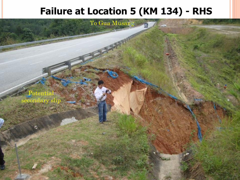
Failure at Location 5 (KM 134) - RHS To Gua Musang
Potential
secondary slip

Failure at Location 5 (KM 134) - RHS
Embankment
(gentler failed
slope)
Cut Slope
(steeper
failed slope)
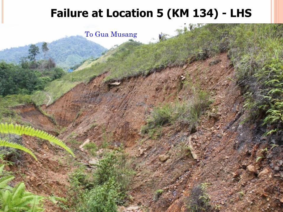
Failure at Location 5 (KM 134) - LHS
To Gua Musang
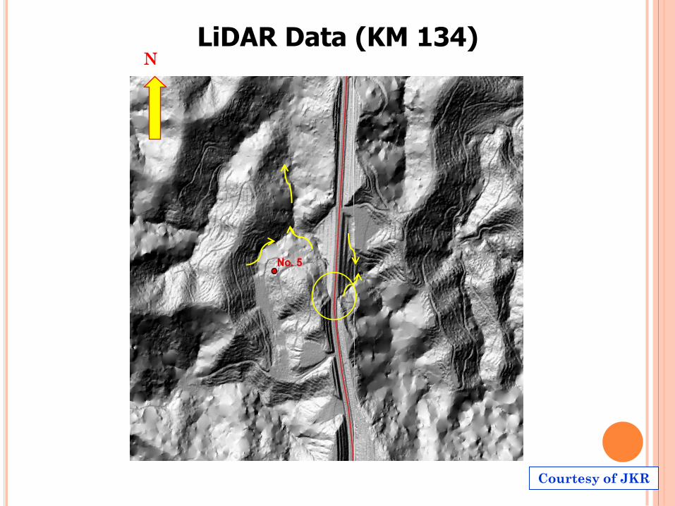
LiDAR Data (KM 134) N
Courtesy of JKR
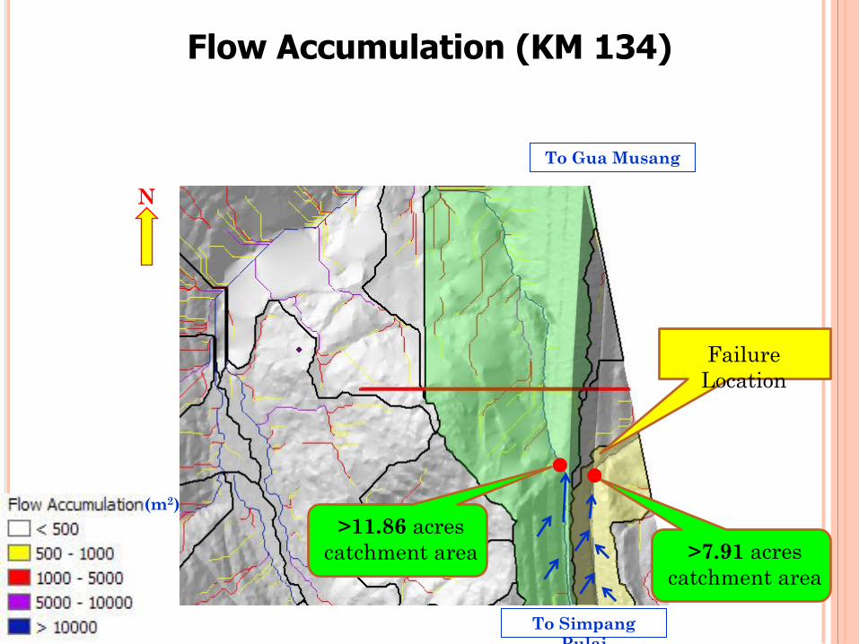
Flow Accumulation (KM 134)
N
Failure
Location
To Gua Musang
To Simpang
Pulai
>7.91 acres
catchment area
(m2)
>11.86 acres
catchment area
Drain built across the original and fill ground suffered
differential settlement.
Broken drain led to erosion of slope.
Splashing of water at the drainage junction led to soil
erosion.
Erosion took place was left unattended for a long
period of time.
No effective inspection and maintenance carried out.
Probable Cause(s) Failure (KM 134)
AMALAN TERBAIK DALAM
REKABENTUK JALAN DI
KAWASAN BERBUKIT PENAMBAHBAIKAN GARIS PANDUAN
PROCUREMENT
53
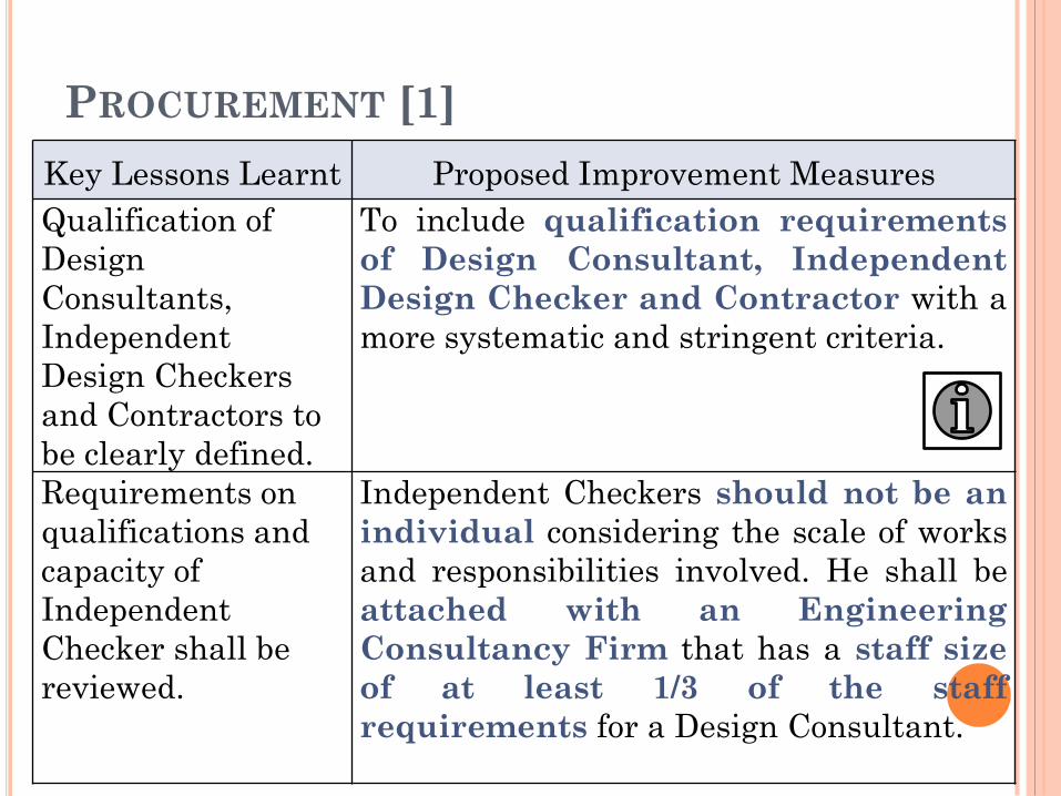
PROCUREMENT [1]
Key Lessons Learnt Proposed Improvement Measures
Qualification of
Design
Consultants,
Independent
Design Checkers
and Contractors to
be clearly defined.
To include qualification requirements
of Design Consultant, Independent
Design Checker and Contractor with a
more systematic and stringent criteria.
Requirements on
qualifications and
capacity of
Independent
Checker shall be
reviewed.
Independent Checkers should not be an
individual considering the scale of works
and responsibilities involved. He shall be
attached with an Engineering
Consultancy Firm that has a staff size
of at least 1/3 of the staff
requirements for a Design Consultant.
54
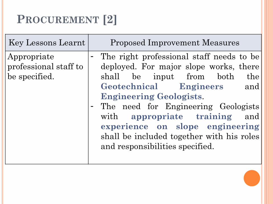
PROCUREMENT [2]
Key Lessons Learnt Proposed Improvement Measures
Appropriate
professional staff to
be specified.
- The right professional staff needs to be
deployed. For major slope works, there
shall be input from both the
Geotechnical Engineers and
Engineering Geologists.
- The need for Engineering Geologists
with appropriate training and
experience on slope engineering
shall be included together with his roles
and responsibilities specified.
55
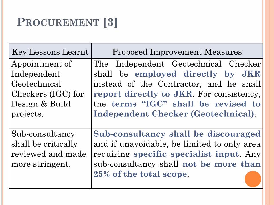
PROCUREMENT [3]
Key Lessons Learnt Proposed Improvement Measures
Appointment of
Independent
Geotechnical
Checkers (IGC) for
Design & Build
projects.
The Independent Geotechnical Checker
shall be employed directly by JKR
instead of the Contractor, and he shall
report directly to JKR. For consistency,
the terms “IGC” shall be revised to
Independent Checker (Geotechnical).
Sub-consultancy
shall be critically
reviewed and made
more stringent.
Sub-consultancy shall be discouraged
and if unavoidable, be limited to only area
requiring specific specialist input. Any
sub-consultancy shall not be more than
25% of the total scope.
56
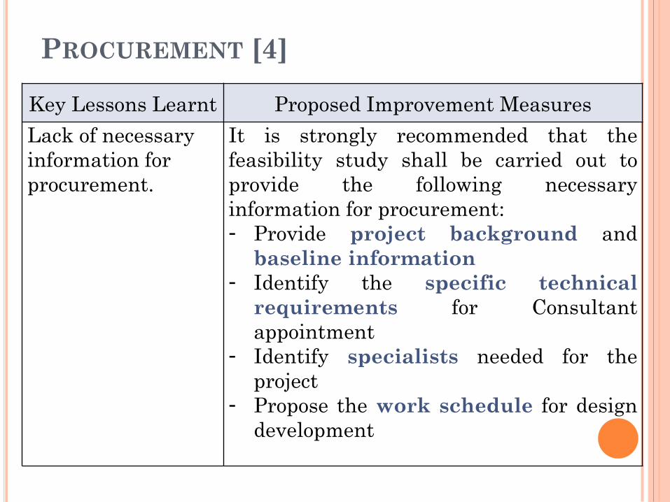
PROCUREMENT [4]
Key Lessons Learnt Proposed Improvement Measures
Lack of necessary
information for
procurement.
It is strongly recommended that the
feasibility study shall be carried out to
provide the following necessary
information for procurement:
- Provide project background and
baseline information
- Identify the specific technical
requirements for Consultant
appointment
- Identify specialists needed for the
project
- Propose the work schedule for design
development
57
PLANNING
58
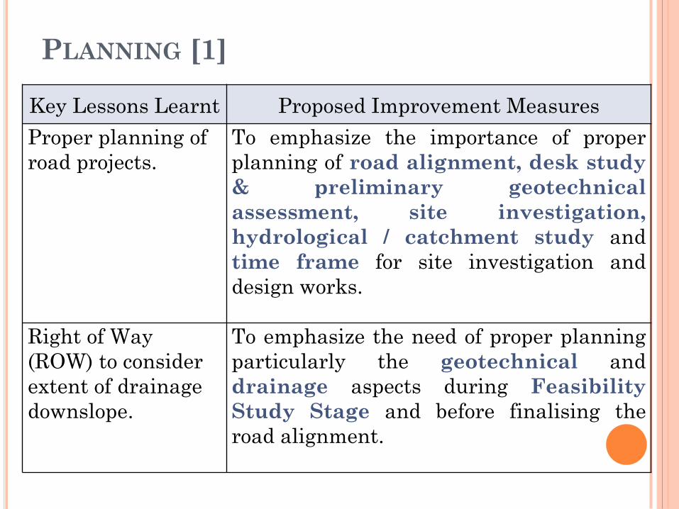
PLANNING [1]
Key Lessons Learnt Proposed Improvement Measures
Proper planning of
road projects.
To emphasize the importance of proper
planning of road alignment, desk study
& preliminary geotechnical
assessment, site investigation,
hydrological / catchment study and
time frame for site investigation and
design works.
Right of Way
(ROW) to consider
extent of drainage
downslope.
To emphasize the need of proper planning
particularly the geotechnical and
drainage aspects during Feasibility
Study Stage and before finalising the
road alignment.
59
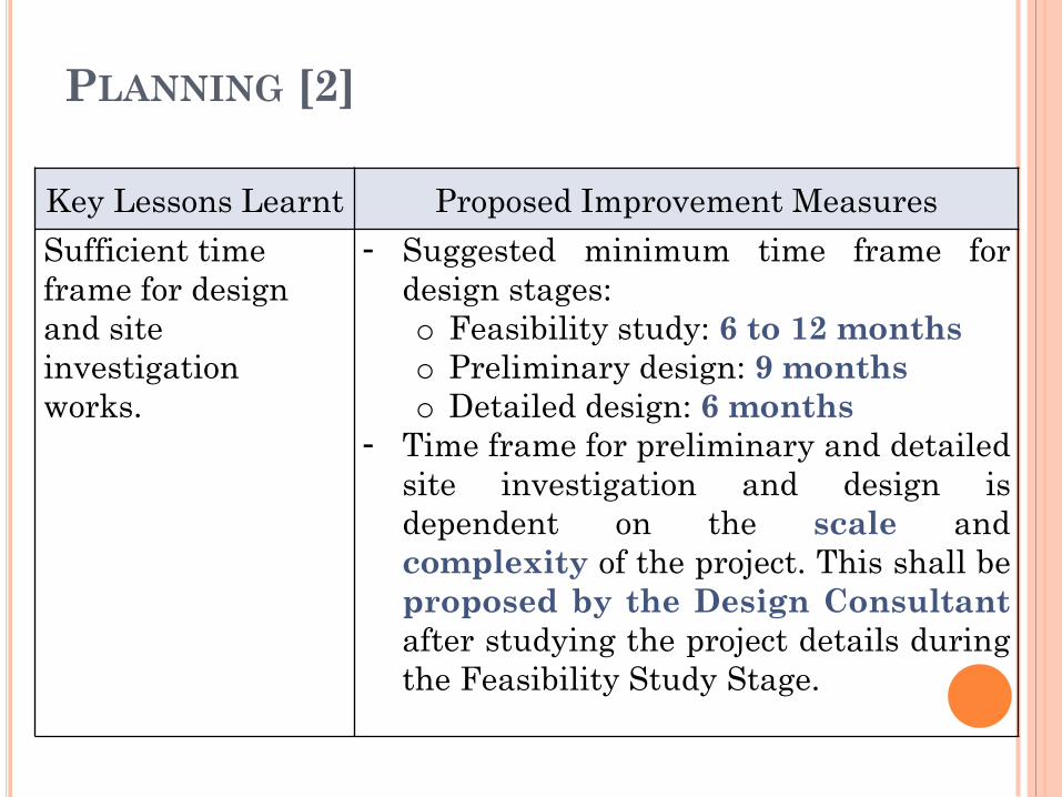
PLANNING [2]
Key Lessons Learnt Proposed Improvement Measures
Sufficient time
frame for design
and site
investigation
works.
- Suggested minimum time frame for
design stages:
o Feasibility study: 6 to 12 months
o Preliminary design: 9 months
o Detailed design: 6 months
- Time frame for preliminary and detailed
site investigation and design is
dependent on the scale and
complexity of the project. This shall be
proposed by the Design Consultant
after studying the project details during
the Feasibility Study Stage.
60
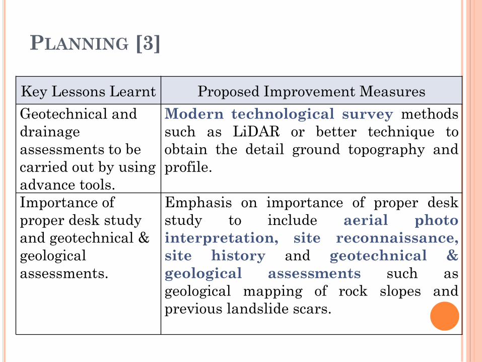
PLANNING [3]
Key Lessons Learnt Proposed Improvement Measures
Geotechnical and
drainage
assessments to be
carried out by using
advance tools.
Modern technological survey methods
such as LiDAR or better technique to
obtain the detail ground topography and
profile.
Importance of
proper desk study
and geotechnical &
geological
assessments.
Emphasis on importance of proper desk
study to include aerial photo
interpretation, site reconnaissance,
site history and geotechnical &
geological assessments such as
geological mapping of rock slopes and
previous landslide scars.
61
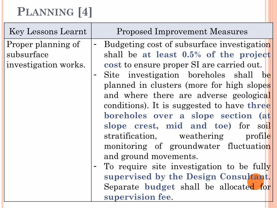
PLANNING [4]
Key Lessons Learnt Proposed Improvement Measures
Proper planning of
subsurface
investigation works.
- Budgeting cost of subsurface investigation
shall be at least 0.5% of the project
cost to ensure proper SI are carried out.
- Site investigation boreholes shall be
planned in clusters (more for high slopes
and where there are adverse geological
conditions). It is suggested to have three
boreholes over a slope section (at
slope crest, mid and toe) for soil
stratification, weathering profile
monitoring of groundwater fluctuation
and ground movements.
- To require site investigation to be fully
supervised by the Design Consultant.
Separate budget shall be allocated for
supervision fee. 62
DESIGN
63
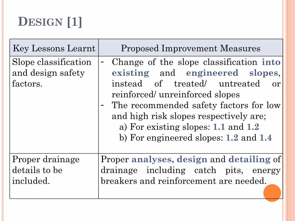
DESIGN [1]
Key Lessons Learnt Proposed Improvement Measures
Slope classification
and design safety
factors.
- Change of the slope classification into
existing and engineered slopes,
instead of treated/ untreated or
reinforced/ unreinforced slopes
- The recommended safety factors for low
and high risk slopes respectively are;
a) For existing slopes: 1.1 and 1.2
b) For engineered slopes: 1.2 and 1.4
Proper drainage
details to be
included.
Proper analyses, design and detailing of
drainage including catch pits, energy
breakers and reinforcement are needed.
64
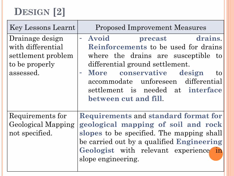
DESIGN [2]
Key Lessons Learnt Proposed Improvement Measures
Drainage design
with differential
settlement problem
to be properly
assessed.
- Avoid precast drains.
Reinforcements to be used for drains
where the drains are susceptible to
differential ground settlement.
- More conservative design to
accommodate unforeseen differential
settlement is needed at interface
between cut and fill.
Requirements for
Geological Mapping
not specified.
Requirements and standard format for
geological mapping of soil and rock
slopes to be specified. The mapping shall
be carried out by a qualified Engineering
Geologist with relevant experience in
slope engineering.
65
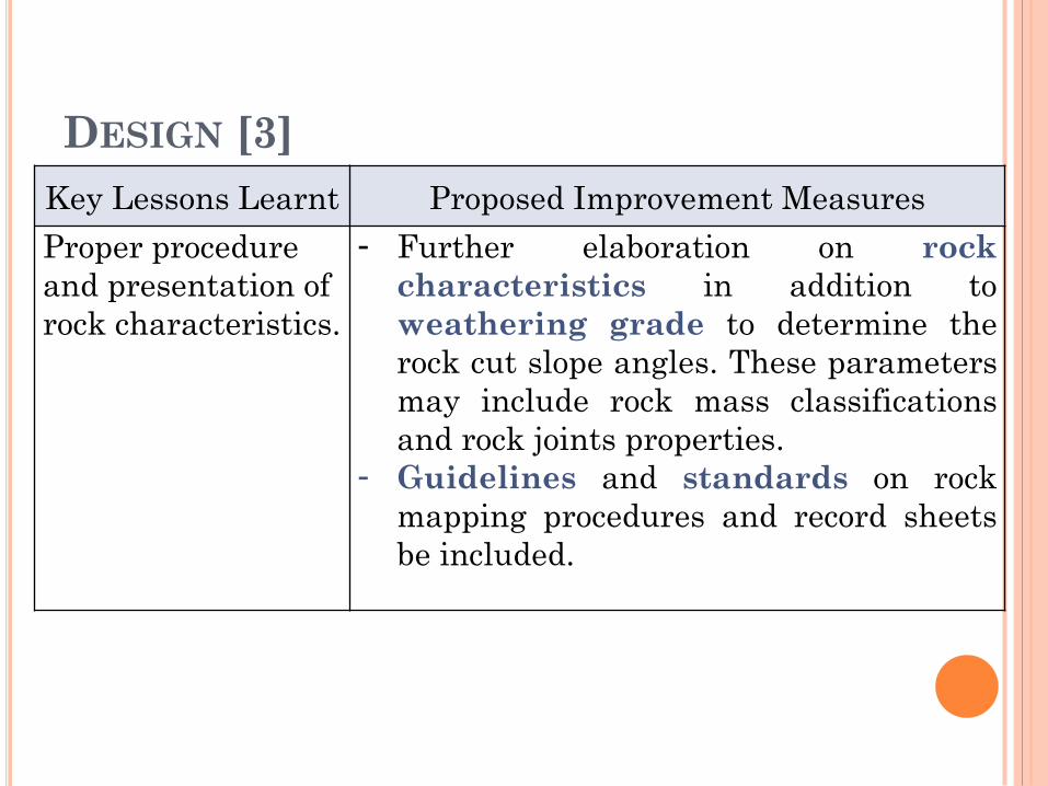
DESIGN [3]
Key Lessons Learnt Proposed Improvement Measures
Proper procedure
and presentation of
rock characteristics.
- Further elaboration on rock
characteristics in addition to
weathering grade to determine the
rock cut slope angles. These parameters
may include rock mass classifications
and rock joints properties.
- Guidelines and standards on rock
mapping procedures and record sheets
be included.
66
CONSTRUCTION
67
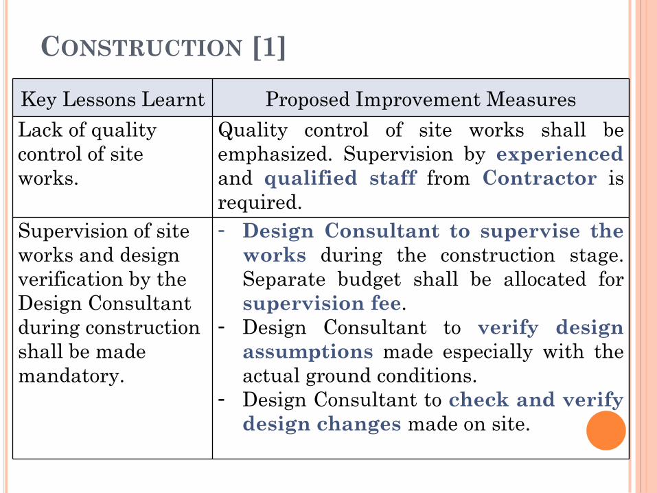
CONSTRUCTION [1]
Key Lessons Learnt Proposed Improvement Measures
Lack of quality
control of site
works.
Quality control of site works shall be
emphasized. Supervision by experienced
and qualified staff from Contractor is
required.
Supervision of site
works and design
verification by the
Design Consultant
during construction
shall be made
mandatory.
- Design Consultant to supervise the
works during the construction stage.
Separate budget shall be allocated for
supervision fee.
- Design Consultant to verify design
assumptions made especially with the
actual ground conditions.
- Design Consultant to check and verify
design changes made on site.
68
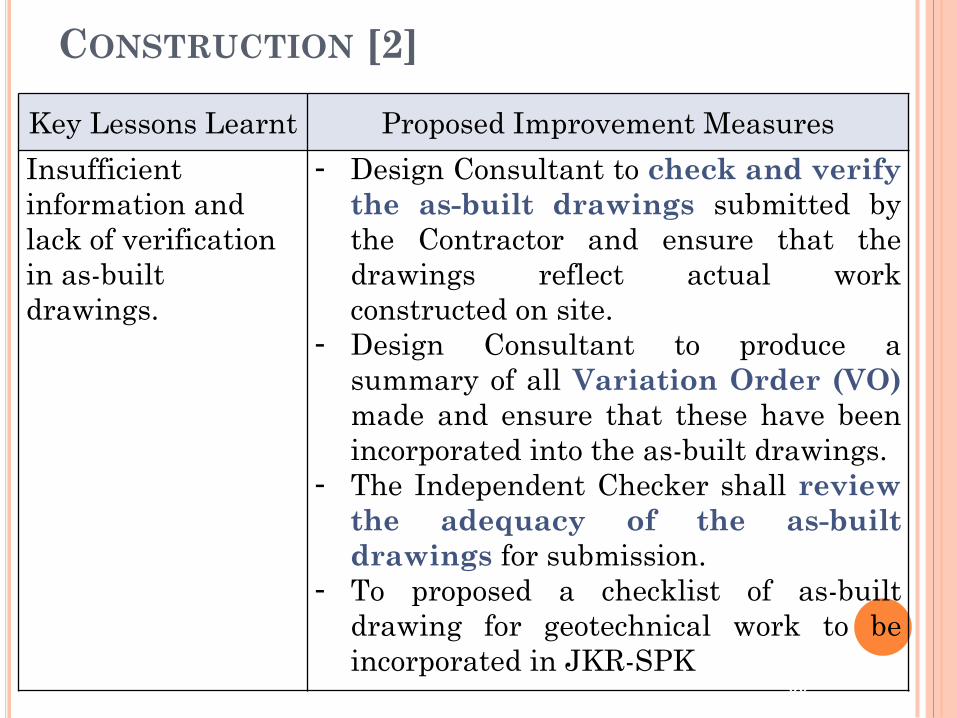
CONSTRUCTION [2]
Key Lessons Learnt Proposed Improvement Measures
Insufficient
information and
lack of verification
in as-built
drawings.
- Design Consultant to check and verify
the as-built drawings submitted by
the Contractor and ensure that the
drawings reflect actual work
constructed on site.
- Design Consultant to produce a
summary of all Variation Order (VO)
made and ensure that these have been
incorporated into the as-built drawings.
- The Independent Checker shall review
the adequacy of the as-built
drawings for submission.
- To proposed a checklist of as-built
drawing for geotechnical work to be
incorporated in JKR-SPK 69
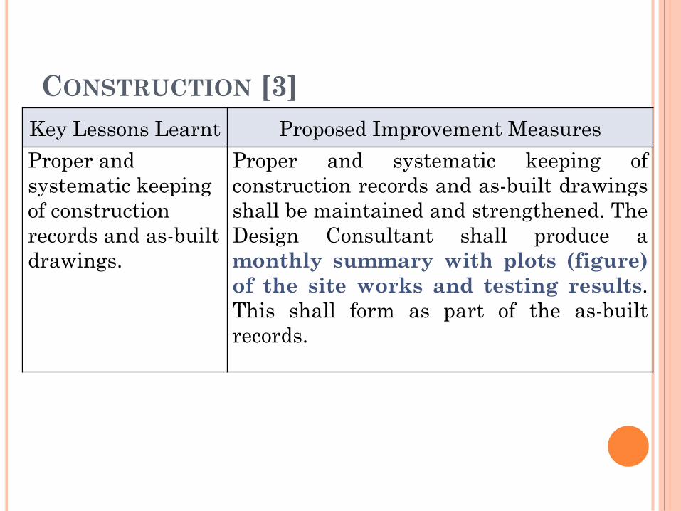
CONSTRUCTION [3]
Key Lessons Learnt Proposed Improvement Measures
Proper and
systematic keeping
of construction
records and as-built
drawings.
Proper and systematic keeping of
construction records and as-built drawings
shall be maintained and strengthened. The
Design Consultant shall produce a
monthly summary with plots (figure)
of the site works and testing results.
This shall form as part of the as-built
records.
70
MAINTENANCE
71
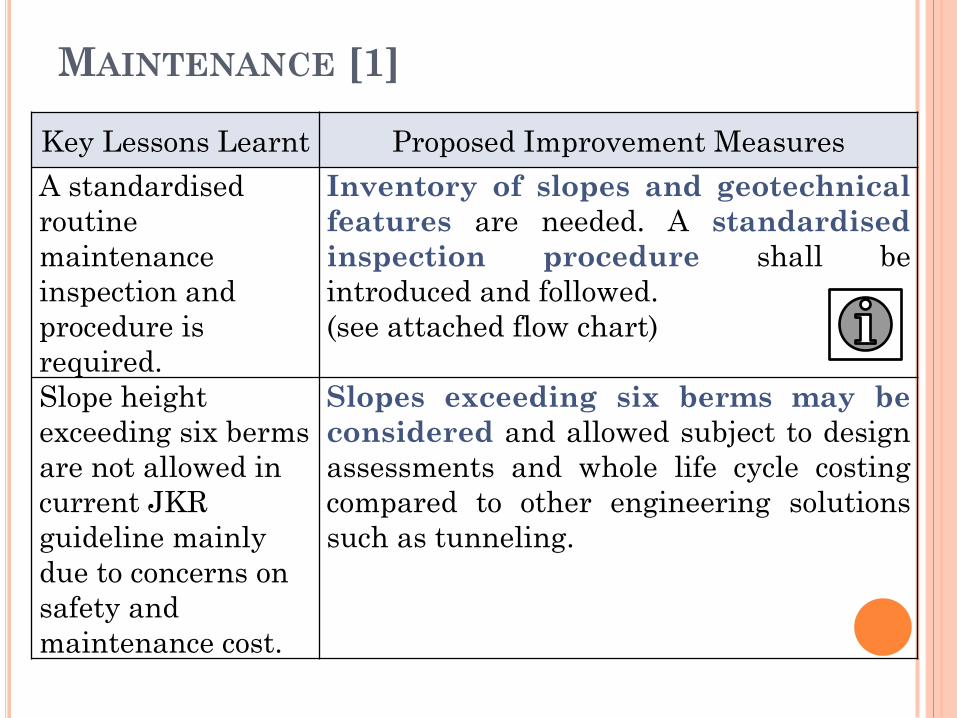
MAINTENANCE [1]
Key Lessons Learnt Proposed Improvement Measures
A standardised
routine
maintenance
inspection and
procedure is
required.
Inventory of slopes and geotechnical
features are needed. A standardised
inspection procedure shall be
introduced and followed.
(see attached flow chart)
Slope height
exceeding six berms
are not allowed in
current JKR
guideline mainly
due to concerns on
safety and
maintenance cost.
Slopes exceeding six berms may be
considered and allowed subject to design
assessments and whole life cycle costing
compared to other engineering solutions
such as tunneling.
72
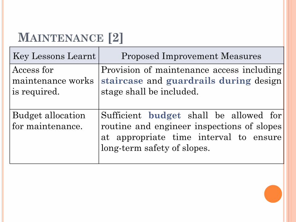
MAINTENANCE [2]
Key Lessons Learnt Proposed Improvement Measures
Access for
maintenance works
is required.
Provision of maintenance access including
staircase and guardrails during design
stage shall be included.
Budget allocation
for maintenance.
Sufficient budget shall be allowed for
routine and engineer inspections of slopes
at appropriate time interval to ensure
long-term safety of slopes.
73
KESIMPULAN
74
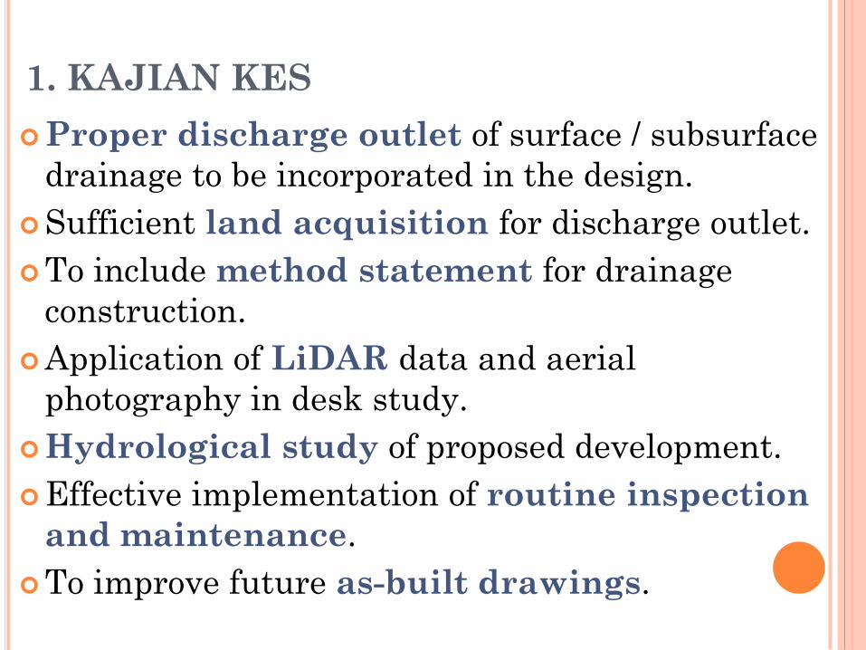
1. KAJIAN KES
Proper discharge outlet of surface / subsurface
drainage to be incorporated in the design.
Sufficient land acquisition for discharge outlet.
To include method statement for drainage
construction.
Application of LiDAR data and aerial
photography in desk study.
Hydrological study of proposed development.
Effective implementation of routine inspection
and maintenance.
To improve future as-built drawings.
2. AMALAN TERBAIK DALAM
REKABENTUK JALAN DI KAWASAN
BERBUKIT
Suggestions for improvement as a result of this
study should be noted in order to improve
the existing guidelines, particularly guidelines
provided by;
Cawangan Kerja Cerun,
Cawangan Jalan,
Bahagian Senggara Fasiliti Jalan dan
Cawangan Kejuruteraan Jalan & Geoteknik

TERIMA KASIH
77

QUALIFICATIONS OF SENIOR
DESIGN CONSULTANT
(GEOTECHNICAL)
- Registered Professional Engineers with Board of
Engineers, Malaysia (BEM) with minimum of five
years of relevant design experience. Suggestions on
nurturing of Malaysian sustainable Design
Consultants are described by Gue et al. (2011).
- The roles and responsibilities of the Design
Consultant should be clearly stated during the
appointment stage. One important requirement is
that the Consultant has a separate and
independent team to carry out in-house
checking and review of the designs. 78
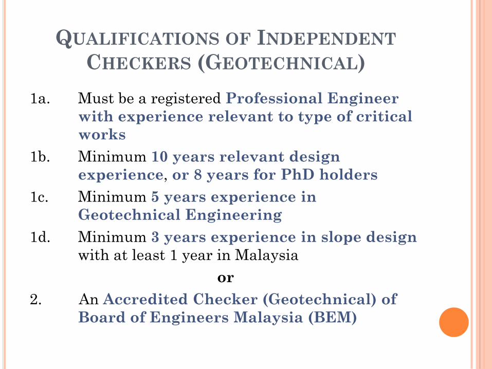
QUALIFICATIONS OF INDEPENDENT
CHECKERS (GEOTECHNICAL)
1a. Must be a registered Professional Engineer
with experience relevant to type of critical
works
1b. Minimum 10 years relevant design
experience, or 8 years for PhD holders
1c. Minimum 5 years experience in
Geotechnical Engineering
1d. Minimum 3 years experience in slope design
with at least 1 year in Malaysia
or
2. An Accredited Checker (Geotechnical) of
Board of Engineers Malaysia (BEM)
79
QUALIFICATIONS OF CONTRACTOR
The Contractor’s team shall include a
responsible person who is a Professional
Engineer and has at least 10 years of
relevant experience to oversee
construction of the entire road works
80
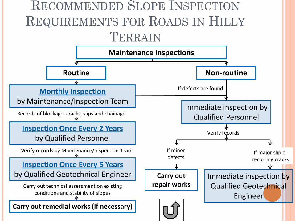
Carry out technical assessment on existing conditions and stability of slopes
RECOMMENDED SLOPE INSPECTION
REQUIREMENTS FOR ROADS IN HILLY
TERRAIN Maintenance Inspections
Monthly Inspection by Maintenance/Inspection Team
Immediate inspection by Qualified Personnel
Carry out remedial works (if necessary)
Routine Non-routine
Inspection Once Every 2 Years by Qualified Personnel
Inspection Once Every 5 Years by Qualified Geotechnical Engineer
Verify records by Maintenance/Inspection Team
Verify records
Immediate inspection by Qualified Geotechnical
Engineer
Records of blockage, cracks, slips and chainage
If defects are found
81
If minor defects
Carry out repair works
If major slip or recurring cracks