implementation of wimax ieee802.16d baseband transceiver ... · baseband transceiver on multi-core...
TRANSCRIPT
Implementation of WIMAX IEEE802.16d Baseband Transceiver on
Multi-Core Software-Defined Radio Platform
MOHAMMED ABOUD KADHIM1, WIDAD ISMAIL
2
School of Electrical and Electronics Engineering, Universiti Sains Malaysia, Seri Ampangan, 14300
Nibong Tebal, Seberang Perai Selatan, Pulau Pinang, Malaysia
1Tel: +6 0174750498, Email: [email protected]
Abstract: IEEE 802.16d was developed for WIMAX wireless communication, which is based on orthogonal
frequency division multiplexing (OFDM) technology, to enable advancement towards 4G The last decade have
seen growing importance place on research in wireless communication system. A recent surge of research on
WIMAX has given us opportunities and challenges. In this paper, we describe the implementation of WIMAX
baseband transceiver on multi-core Software-defined radio (SDR) platform. This work presents a new approach
to the adaptation of WIMAX technology on the basis of SFF SDR development platform. The proposed
WIMAX system was modelled-tested, and its performance was found to comply with Stanford University
Interim (SUI) Channel Models that have been elected for the wireless channel in the simulation process. The
performance results of the simulated on different modulation systems were also compared among themselves.
Key-Words: - WIMAX, SFF SDR, OFDM, RS, Coding, SUI, AWGN.
1- Introduction
Broadband access technology has significant influences
in the telecommunication industry. It does not only
provide faster web surfing but also quicker file
downloads, several multimedia applications and reliable
voice communications. Today broadband users are
restricted to digital subscriber line (DSL) technology,
which provides broadband over twisted-pair wires and
cable modem technology which delivers over coaxial
cable. Both of these wire line infrastructures are highly
expensive and time consuming to be deployed compared
to the wireless technology. Another way of getting
broadband access is through satellite service but it is
costly and there is a half second delay between the data
transmission and reception. Wireless technology has also
clear advantage in rural areas and developing countries
which lacks wire infrastructures for broadband services.
Worldwide interoperability for microwave access
(WIMAX) is a broadband wireless technology which
brings broadband experience to a Wireless context. There
are two different types of broadband wireless services.
One is fixed wireless broadband which is similar to the
traditional fixed line broadband access technology like
DSL or cable modem but using wireless as a medium of
transmission. Another type is broadband wireless, also
known as mobile broadband which has additional
functionality of portability, mobility and nomadicity.
WIMAX promises to solve the last mile problem which
refers to the expense and time needed to connect
individual homes and offices to trunk route for
communications. WIMAX also offers higher peak
data rates and greater flexibility than 3G networks
[1]. For this purpose, the Software Define Radio
(SDR) technology is used at present. SDR allows
coexistence of different independent standards,
protocols, and services. This signal processing
approach is broadly spreading given that
reprogramming and reconfiguring of mobile and
fixed devices is of great importance. Due to the
availability of SDR in the device architecture, a user
can update and replace necessary services without
changing the hardware.
2-WIMAX 802.16-2004
Earlier version known as 802.16a that was updated
to 802.16-2004 (also known as 802.16d) is a
WIMAX standard that supports fixed non-line of
sight (NLOS) wireless internet services thus
forming a point to multipoint deployment scenario.
The basic goal of 802.16-2004 standard was to
provide a stationary wireless transmission with data
rates higher than those provided by DSL and T1,
this feature makes fixed WIMAX an alternative for
cable, DSL and T1. 802.16-2004 uses Orthogonal
Frequency Division Multiplexing (OFDM) for
WSEAS TRANSACTIONS on COMMUNICATIONS Mohammed Aboud Kadhim, Widad Ismail
ISSN: 1109-2742 301 Issue 5, Volume 9, May 2010
transmission of data thus serving a large number of
users in time division manner in round robin
fashion. Some of the silent features of 802.16-2004
standards are [2]:
• Designed to provide Fixed NLOS broadband
services to Fixed, Nomadic and Portable users
• 256 OFDM PHY with 64QAM, 16QAM,
QPSK, and BPSK modulation techniques.
• Support for Advance antenna and Adaptive
modulation & coding techniques.
• Facilitates the use of point-to-multipoint mesh
topology
• Low latency for delay sensitive services, thus
improving on QoS parameters
• Support for both: Time Division Duplexing
(TDD) and Frequency Division Duplexing
(FDD)
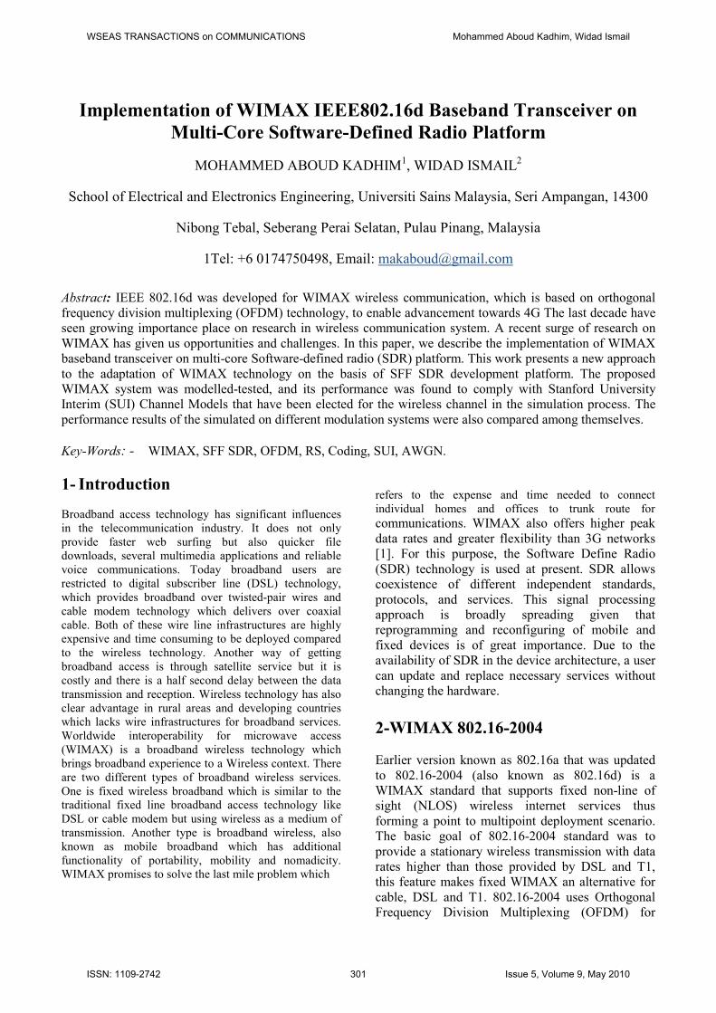
3. SFF SDR Development Platforms
The SFF SDR Development Platform consists of
three distinct hardware modules that offer flexible
development capabilities: the digital processing,
data conversion, and RF module. The digital
processing module uses a Virtex-4 FPGA and a
DM6446 SoC to offer developers the necessary
performance for implementing custom IP and
acceleration functions with varying requirements
from one protocol to another supported on the same
hardware. The data conversion module is equipped
with dual-channel analog-to-digital and digital-to-
analog converters. The RF module covers a variety
of frequency ranges in transmission and reception,
allowing it to support a wide range of applications
[3].
Fig .1. SFF SDR Development Platform[3]
3.1 System performance analysis and
optimization target
MathWorks and Texas Instruments (TI), the two
companies responsible for the development of
Matlab/Simulink, are currently working on the
development of a DSP development tool that users
can use through Simulink. The object modules,
designed to meet their own needs, the programming
system, which is implemented through Real- Time
Workshop, and the S-function with the TLC (Target
Language Compiler) Function of the system design,
when completed, can be directly converted to the
most commonly used DSP programming language.
The DSP, in conjunction with the TI software, Code
Composer Studio, is completed in combination with
the DSP hardware. Thus, through this development
tool, users can work together to complete the design
and simulation on the Simulink; however, it cannot
provide the convenience of design that could
increase the set count on the efficiency.
3.1.1 System integration and implementation of
workflow
In the development and testing of IEEE 802.16d
Wireless MAN-OFDM PHY, the specifications of
communication transfer have varying systems,
which are based on our needs under Simulink
mentioned in the proposed system for WIMAX
IEEE 802.16d. For our study, we used the standard
communication system box with a map provided by
Matlab, which contains the following: Internal
Communications Blockset, Signal processing
Blockset, and Simulink Blockset. These correspond
to our use of the hardware development platform for
SFF SDR DP Blockset. The overall WIMAX PHY
system construction is opened in the Simulink
interface and Matlab is used to communicate the
internal functions of RTW and TLC. We intend to
build a finished system into a module, in accordance
with the code of each block. Through this, we can
perform the compilation and completion that will be
automatically compiled in Matlab CCS connecting
knot. The CCS establishes a corresponding module
under the file name "Project." We then correct the
generated C code and conduct compilation,
debugging, and analysis. We then download our
work into to the DSP. The overall system workflow
is shown in Figure 3. The figure shows the system
built based on the Simulink-established IEEE
802.16d Wireless MAN-OFDM PHY standard
modules. The first step is the configuration by
Simulink of the parameters interface and
development platform into the conduct of the
connecting node configuration. Information will be
set to leave the bulk form of a fixed number of
patterns, and the RTW system development module
is set to be transferred and replaced by C language.
Meanwhile, the TLC file option SDR development
of modules and the set up Simulink system
development are scheduled for DSP link module by
an external module through the executive.
Configuration of the IEEE 802.16d Wireless MAN-
WSEAS TRANSACTIONS on COMMUNICATIONS Mohammed Aboud Kadhim, Widad Ismail
ISSN: 1109-2742 302 Issue 5, Volume 9, May 2010
OFDM PHY may be achieved through the DSP
Options Block Simulink to develop interfaces
connecting node, development platform, and CCS.
The use of the DSP Options Block and the Compiler
Options allow us to optimize the system and the
executive profit use. Moreover, future compiler
optimization can be conducted through the Block. In
the SFF SDR Development Platform of the DSP
configuration, three kinds of memory are used:
L1DRAM (8 KB), L2RAM (64 KB), and SDRAM
(8 MB). The L1DRAM and L2RAM are used for
the internal memory, while the SDRAM is used for
the external memory. Due to the retention of
internal memory, the speeds become quicker; thus,
if information is to be placed in the internal memory
in the system as a whole, the speeds and the
executive would enhance performance Thus, the
CMD File Generator Block for Development
Platform can be conducted into the memory settings
[3].
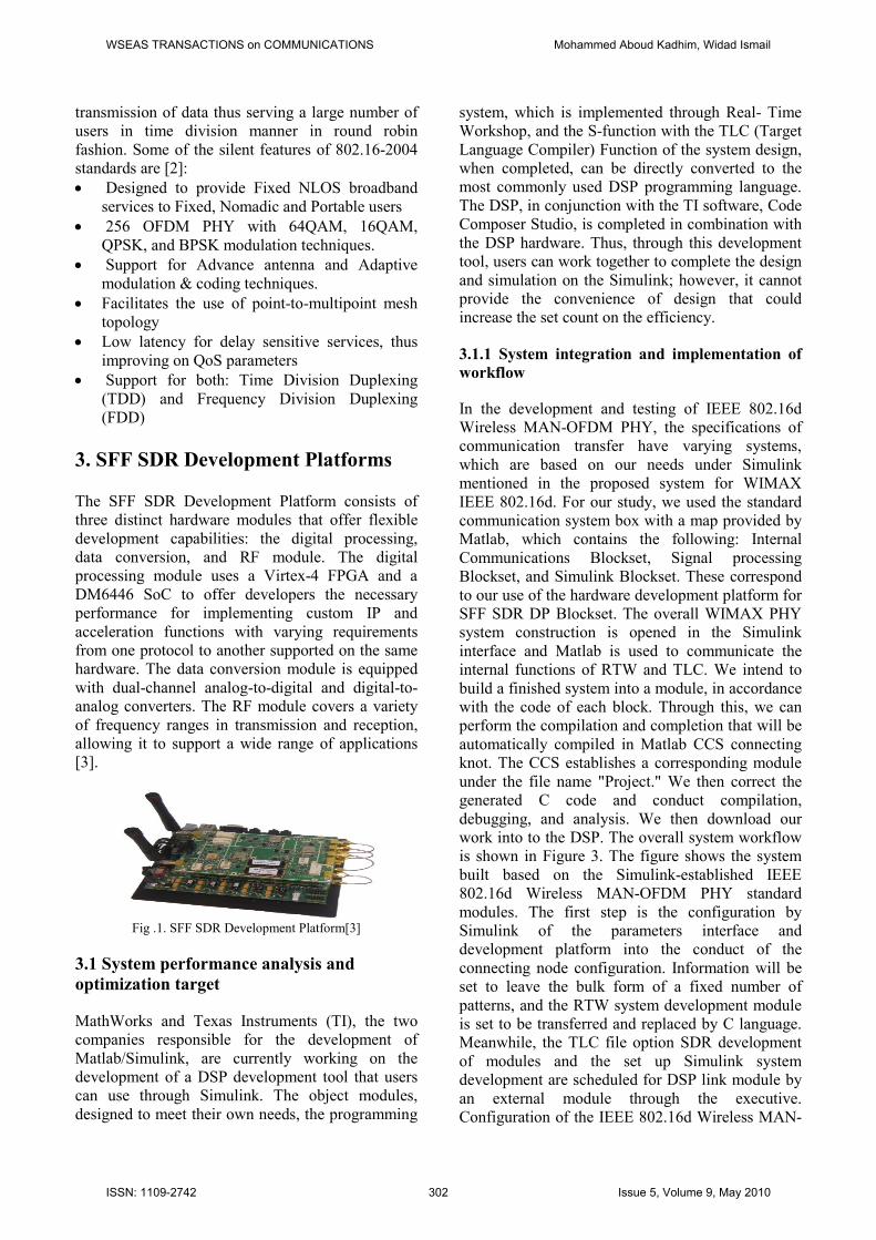
Fig .2. Schematic diagram of the system workflow actions [3].
3.1.2 TLC and RTW
Target Language Compiler (TLC) is a Matlab
program that uses syntax. Developers using the
RTW tool can use the TLC to create self-designed C
syntax language code by adding to the executive
after the RTW-generated C language code or design.
The use the S-function in the input and output of the
set can design its own system for C programming
and create Simulink objects in the box to use;
however, RTW is only responsible for producing the
C language program yards. It will not check the
correct use of grammar; thus, performing actions or
debugging code requires conducting C into the
editor. Moreover, in the design of TLC, all of the
program features in metropolis are the function of
the type, as shown in Figure 3. Thus, the designer
can use the RTW to generate the required developer
as long as the C program is appropriately used
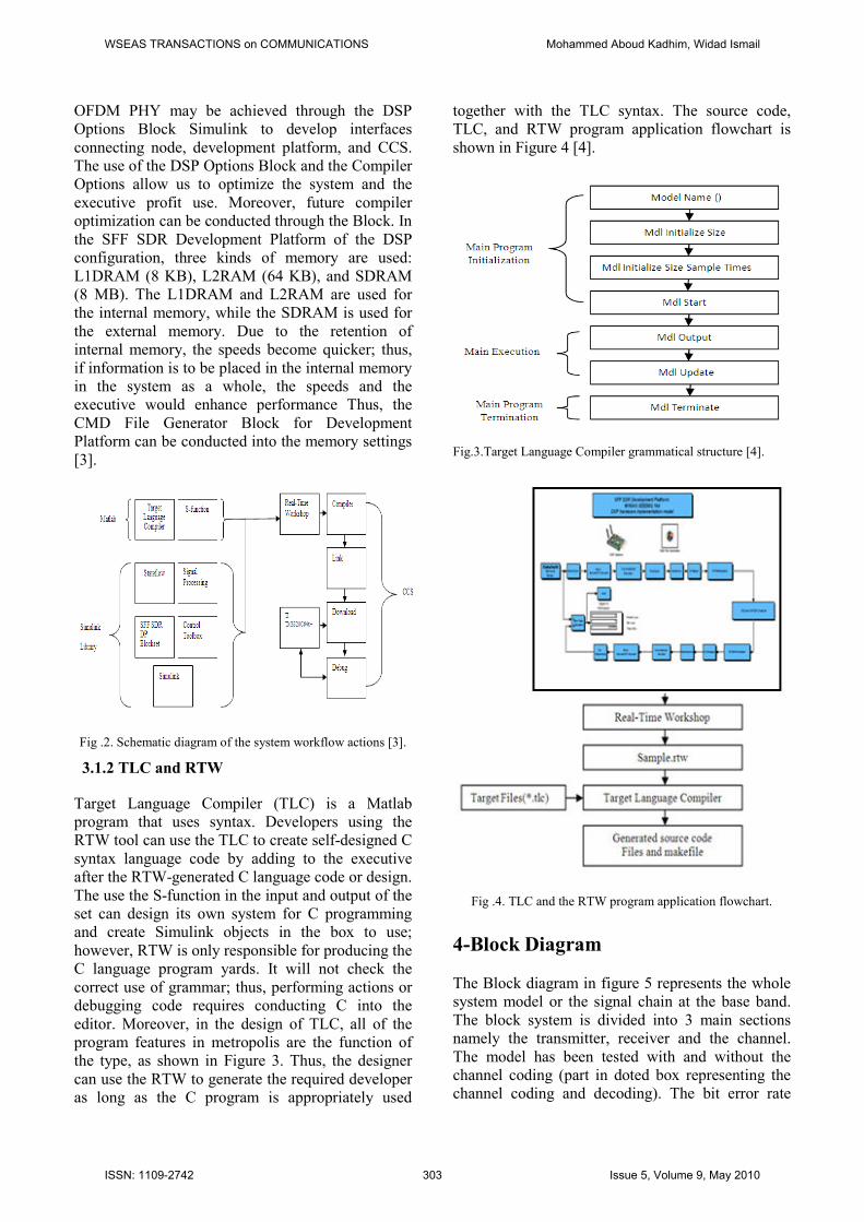
together with the TLC syntax. The source code,
TLC, and RTW program application flowchart is
shown in Figure 4 [4].
Fig.3.Target Language Compiler grammatical structure [4].
Fig .4. TLC and the RTW program application flowchart.
4-Block Diagram
The Block diagram in figure 5 represents the whole
system model or the signal chain at the base band.
The block system is divided into 3 main sections
namely the transmitter, receiver and the channel.
The model has been tested with and without the
channel coding (part in doted box representing the
channel coding and decoding). The bit error rate
WSEAS TRANSACTIONS on COMMUNICATIONS Mohammed Aboud Kadhim, Widad Ismail
ISSN: 1109-2742 303 Issue 5, Volume 9, May 2010
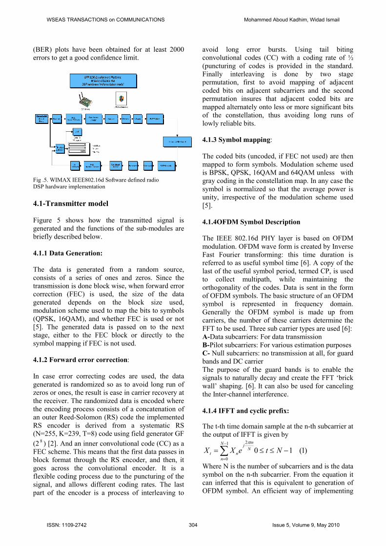
(BER) plots have been obtained for at least 2000
errors to get a good confidence limit.
Fig .5. WIMAX IEEE802.16d Software defined radio
DSP hardware implementation
4.1-Transmitter model
Figure 5 shows how the transmitted signal is
generated and the functions of the sub-modules are
briefly described below.
4.1.1 Data Generation:
The data is generated from a random source,
consists of a series of ones and zeros. Since the
transmission is done block wise, when forward error
correction (FEC) is used, the size of the data
generated depends on the block size used,
modulation scheme used to map the bits to symbols
(QPSK, 16QAM), and whether FEC is used or not
[5]. The generated data is passed on to the next
stage, either to the FEC block or directly to the
symbol mapping if FEC is not used.
4.1.2 Forward error correction:
In case error correcting codes are used, the data
generated is randomized so as to avoid long run of
zeros or ones, the result is ease in carrier recovery at
the receiver. The randomized data is encoded where
the encoding process consists of a concatenation of
an outer Reed-Solomon (RS) code the implemented
RS encoder is derived from a systematic RS
(N=255, K=239, T=8) code using field generator GF
(28) [2]. And an inner convolutional code (CC) as a
FEC scheme. This means that the first data passes in
block format through the RS encoder, and then, it
goes across the convolutional encoder. It is a
flexible coding process due to the puncturing of the
signal, and allows different coding rates. The last
part of the encoder is a process of interleaving to
avoid long error bursts. Using tail biting
convolutional codes (CC) with a coding rate of ½
(puncturing of codes is provided in the standard.
Finally interleaving is done by two stage
permutation, first to avoid mapping of adjacent
coded bits on adjacent subcarriers and the second
permutation insures that adjacent coded bits are
mapped alternately onto less or more significant bits
of the constellation, thus avoiding long runs of
lowly reliable bits.
4.1.3 Symbol mapping:
The coded bits (uncoded, if FEC not used) are then
mapped to form symbols. Modulation scheme used
is BPSK, QPSK, 16QAM and 64QAM unless with
gray coding in the constellation map. In any case the
symbol is normalized so that the average power is
unity, irrespective of the modulation scheme used
[5].
4.1.4OFDM Symbol Description
The IEEE 802.16d PHY layer is based on OFDM
modulation. OFDM wave form is created by Inverse
Fast Fourier transforming: this time duration is
referred to as useful symbol time [6]. A copy of the
last of the useful symbol period, termed CP, is used
to collect multipath, while maintaining the
orthogonality of the codes. Data is sent in the form
of OFDM symbols. The basic structure of an OFDM
symbol is represented in frequency domain.
Generally the OFDM symbol is made up from
carriers, the number of these carriers determine the
FFT to be used. Three sub carrier types are used [6]:
A-Data subcarriers: For data transmission
B-Pilot subcarriers: For various estimation purposes
C- Null subcarriers: no transmission at all, for guard
bands and DC carrier
The purpose of the guard bands is to enable the
signals to naturally decay and create the FFT ‘brick
wall’ shaping. [6]. It can also be used for canceling
the Inter-channel interference.
4.1.4 IFFT and cyclic prefix:
The t-th time domain sample at the n-th subcarrier at
the output of IFFT is given by
)1(101
0
2
−≤≤=∑−
=
NteXXN
n
N
tnj
nt
π
Where N is the number of subcarriers and is the data
symbol on the n-th subcarrier. From the equation it
can inferred that this is equivalent to generation of
OFDM symbol. An efficient way of implementing
WSEAS TRANSACTIONS on COMMUNICATIONS Mohammed Aboud Kadhim, Widad Ismail
ISSN: 1109-2742 304 Issue 5, Volume 9, May 2010
IDFT is by inverse fast Fourier transform (IFFT).
Hence IFFT is used in generation of OFDM symbol.
The addition of cyclic prefix is done on the time
domain symbol obtained after IFFT. The IFFT size
(‘N’ value) is considered as 256 in simulations. This
data is fed to the two channels AWGN and SUI
which represents Stanford University Interim
Channel Models and also implements multipath as
shown in Figure 5,[7].
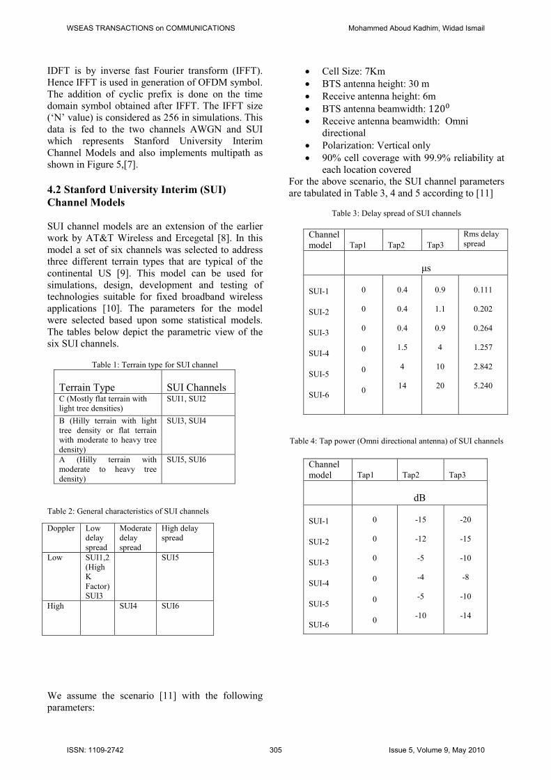
4.2 Stanford University Interim (SUI)
Channel Models
SUI channel models are an extension of the earlier
work by AT&T Wireless and Ercegetal [8]. In this
model a set of six channels was selected to address
three different terrain types that are typical of the
continental US [9]. This model can be used for
simulations, design, development and testing of
technologies suitable for fixed broadband wireless
applications [10]. The parameters for the model
were selected based upon some statistical models.
The tables below depict the parametric view of the
six SUI channels.
Table 1: Terrain type for SUI channel
Terrain Type SUI Channels C (Mostly flat terrain with
light tree densities)
SUI1, SUI2
B (Hilly terrain with light
tree density or flat terrain
with moderate to heavy tree
density)
SUI3, SUI4
A (Hilly terrain with
moderate to heavy tree
density)
SUI5, SUI6
Table 2: General characteristics of SUI channels
We assume the scenario [11] with the following
parameters:
• Cell Size: 7Km
• BTS antenna height: 30 m
• Receive antenna height: 6m
• BTS antenna beamwidth: 120�
• Receive antenna beamwidth: Omni
directional
• Polarization: Vertical only
• 90% cell coverage with 99.9% reliability at
each location covered
For the above scenario, the SUI channel parameters
are tabulated in Table 3, 4 and 5 according to [11]
Table 3: Delay spread of SUI channels
Channel
model Tap1 Tap2 Tap3
Rms delay
spread
µs
SUI-1
SUI-2
SUI-3
SUI-4
SUI-5
SUI-6
0
0
0
0
0
0
0.4
0.4
0.4
1.5
4
14
0.9
1.1
0.9
4
10
20
0.111
0.202
0.264
1.257
2.842
5.240
Table 4: Tap power (Omni directional antenna) of SUI channels
Channel
model Tap1 Tap2 Tap3
dB
SUI-1
SUI-2
SUI-3
SUI-4
SUI-5
SUI-6
0
0
0
0
0
0
-15
-12
-5
-4
-5
-10
-20
-15
-10
-8
-10
-14
Doppler Low
delay
spread
Moderate
delay
spread
High delay
spread
Low SUI1,2
(High
K
Factor)
SUI3
SUI5
High SUI4 SUI6
WSEAS TRANSACTIONS on COMMUNICATIONS Mohammed Aboud Kadhim, Widad Ismail
ISSN: 1109-2742 305 Issue 5, Volume 9, May 2010
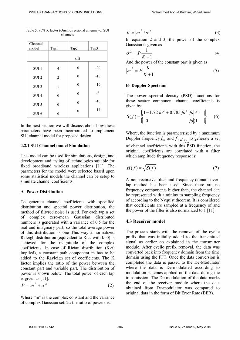
Table 5: 90% K factor (Omni directional antenna) of SUI
channels
Channel
model Tap1 Tap2 Tap3
dB
SUI-1
SUI-2
SUI-3
SUI-4
SUI-5
SUI-6
4
2
1
0
0
0
0
0
0
0
0
0
-20
-15
-10
-8
-10
-14
In the next section we will discuss about how these
parameters have been incorporated to implement
SUI channel model for proposed design.
4.2.1 SUI Channel model Simulation
This model can be used for simulations, design, and
development and testing of technologies suitable for
fixed broadband wireless applications [11]. The
parameters for the model were selected based upon
some statistical models the channel can be setup to
simulate channel coefficients.
A- Power Distribution
To generate channel coefficients with specified
distribution and spectral power distribution, the
method of filtered noise is used. For each tap a set
of complex zero-mean Gaussian distributed
numbers is generated with a variance of 0.5 for the
real and imaginary part, so the total average power
of this distribution is one This way a normalized
Raleigh distribution (equivalent to Rice with k=0) is
achieved for the magnitude of the complex
coefficients. In case of Rician distribution (K>0
implied), a constant path component m has to be
added to the Rayleigh set of coefficients. The K
factor implies the ratio of the power between the
constant part and variable part. The distribution of
power is shown below. The total power of each tap
is given as [11]:
)2(22σ+= mP
Where “m” is the complex constant and the variance
of complex Gaussian set. 2σ the ratio of powers is:
)3(/ 22σmK =
In equation 2 and 3, the power of the complex
Gaussian is given as
)4(1
12
+=
KPσ
And the power of the constant part is given as
)5(1
2
+=
K
KPm
B- Doppler Spectrum
The power spectral density (PSD) functions for
these scatter component channel coefficients is
given by:
)6(10
1785.072.11)(
42
⟩
≤+−=
fo
fofofofS
Where, the function is parameterized by a maximum
Doppler frequency �� and ����
� to generate a set
of channel coefficients with this PSD function, the
original coefficients are correlated with a filter
which amplitude frequency response is:
)7()()( fSfH =
A non recursive filter and frequency-domain over-
lap method has been used. Since there are no
frequency components higher than, the channel can
be represented with a minimum sampling frequency
of according to the Nyquist theorem. It is considered
that coefficients are sampled at a frequency of and
the power of the filter is also normalized to 1 [11].
4.3 Receiver model
The process starts with the removal of the cyclic
prefix that was initially added to the transmitted
signal as earlier on explained in the transmitter
module. After cyclic prefix removal, the data was
converted back into frequency domain from the time
domain using the FFT. Once the data conversion is
completed the data is passed to the De-Modulator
where the data is De-modulated according to
modulation schemes applied on the data during the
transmission. The De-modulation of the data marks
the end of the receiver module where the data
obtained from De-modulator was compared to
original data in the form of Bit Error Rate (BER).
WSEAS TRANSACTIONS on COMMUNICATIONS Mohammed Aboud Kadhim, Widad Ismail
ISSN: 1109-2742 306 Issue 5, Volume 9, May 2010
5. System parameters
The reference model specifies a number of
parameters that can be found in Table (6, 7) Table (6) system parameters
BW 1.75MHz
N used 200
n-sampling factor 8/7
f∆ -subcarrier spacing 7.8KHz
Tb-useful symbol time 12.8ms
Tg-cyclic prefix time 1/4
Ts-OFDM symbol time 16ms
Table (7) system parameters
Modulation NCPC NCBPS
BPSK 1 192
QPSK 2 384
16-QAM 4 768
64-QAM 6 115
6. Simulation Results
In this section the simulation results along with the
underlying assumptions are presented. The basic
aim of this work is to study the physical layer of
WIMAX 802.16d and the corresponding results.
First the performance of the system is investigated
by using AWGN channel and then SUI channel
[11]. The worst performance of the SUI channel is
due to multipath effect, delay spread and Doppler
effects. Although the impact of the delay spread and
the Doppler effect is low so that the major
degradation in the performance is due to the
multipath effects. There are various methods to
reduce the multipath effect. In this model the
simulation of the system is repeated and the number
of transmitted bits and bit errors are calculated for
each simulation. In the end BER rate is estimated as
the ratio of the total number of observed errors and
the total number of transmitted bits. Let us consider
the case system using BPSK, QPSK, 16-QAMand
64-QAM as a modulation scheme and AWGN as a
channel. The total number of transmitted bits for 3
OFDM symbols is 1152 bits. If the simulation is
repeated 500 times then the total number of
transmitted bits is 576000 and the total numbers of
bits that are in error are 62768. In the end BER rate
is estimated from the above calculations. Same
method is adopted for each simulation considered in
this system model. The parameters that can be set
are number of simulated OFDM symbols,
modulation scheme, channel type and range of SNR
(Eb/No (Bit Energy-to-Noise Density) values.
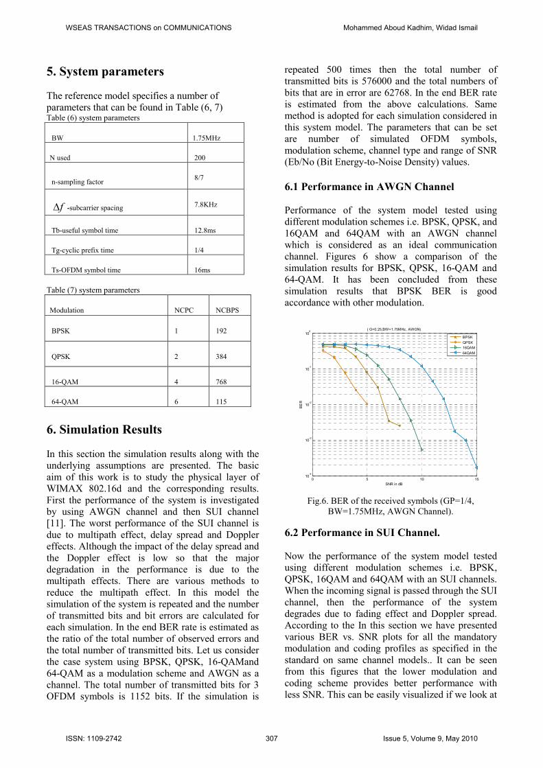
6.1 Performance in AWGN Channel
Performance of the system model tested using
different modulation schemes i.e. BPSK, QPSK, and
16QAM and 64QAM with an AWGN channel
which is considered as an ideal communication
channel. Figures 6 show a comparison of the
simulation results for BPSK, QPSK, 16-QAM and
64-QAM. It has been concluded from these
simulation results that BPSK BER is good
accordance with other modulation.
Fig.6. BER of the received symbols (GP=1/4,
BW=1.75MHz, AWGN Channel).
6.2 Performance in SUI Channel.
Now the performance of the system model tested
using different modulation schemes i.e. BPSK,
QPSK, 16QAM and 64QAM with an SUI channels.
When the incoming signal is passed through the SUI
channel, then the performance of the system
degrades due to fading effect and Doppler spread.
According to the In this section we have presented
various BER vs. SNR plots for all the mandatory
modulation and coding profiles as specified in the
standard on same channel models.. It can be seen
from this figures that the lower modulation and
coding scheme provides better performance with
less SNR. This can be easily visualized if we look at
0 5 10 1510
-4
10-3
10-2
10-1
100
( G=0.25,BW=1.75MHz, AWGN)
SNR in dB
BER
BPSK
QPSK
16QAM
64QAM
WSEAS TRANSACTIONS on COMMUNICATIONS Mohammed Aboud Kadhim, Widad Ismail
ISSN: 1109-2742 307 Issue 5, Volume 9, May 2010
their constellation mapping; larger distance between
adjacent points can tolerate larger noise (which
makes the point shift from the original place) at the
cost of coding rate. By setting threshold SNR,
adaptive modulation schemes can be used to attain
highest transmission speed with a target BER. SNR
required to attain BER level at 103characteristics of
the SUI channel, Rician distribution is used here. So
the channel has three paths consisting of un faded
LOS path and two Rayleigh components. The
required signal is corrupted by the previous
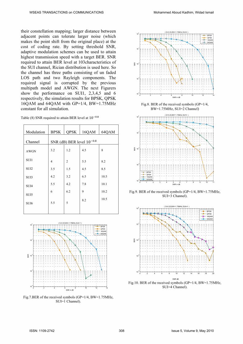
multipath model and AWGN. The next Figurers
show the performance on SUI1, 2,3,4,5 and 6
respectively, the simulation results for BPSK, QPSK
16QAM and 64QAM with GP=1/4, BW=1.75MHz
constant for all simulation.
Table (8) SNR required to attain BER level at 10 �.�
Modulation BPSK QPSK 16QAM 64QAM
Channel SNR (dB) BER level 10 �.�
AWGN
SUI1
SUI2
SUI3
SUI4
SUI5
SUI6
3.2
4
3.5
4.2
5.5
6
5.5
1.2
2
1.5
3.2
4.2
6.2
5
4.5
5.5
4.5
6.5
7.8
9
8.2
8
8.2
8.5
10.5
10.1
10.2
10.5
Fig.7.BER of the received symbols (GP=1/4, BW=1.75MHz,
SUI=1 Channel).
Fig.8. BER of the received symbols (GP=1/4,
BW=1.75MHz, SUI=2 Channel)
Fig.9. BER of the received symbols (GP=1/4, BW=1.75MHz,
SUI=3 Channel).
Fig.10. BER of the received symbols (GP=1/4, BW=1.75MHz,
SUI=4 Channel).
0 2 4 6 8 10 12 14
10-4
10-3
10-2
10-1
100
( G=0.25,BW=1.75MHz,SUI=1 )
SNR in dB
BER
BPSK
QPSK
16QAM
64QAM
0 2 4 6 8 10 12 1410
-4
10-3
10-2
10-1
100
( G=0.25,BW=1.75MHz,SUI=2 )
SNR in dB
DER
BPSK
QPSK
16QAM
64QAM
0 1 2 3 4 5 6 7 8 9 10 1110
-4
10-3
10-2
10-1
100
( G=0.25,BW=1.75MHz,SUI=3 )
SNR in dB
BER
BPSK
QPSK
16QAM
64QAM
0 2 4 6 8 10 12 14 16 18 2010
-4
10-3
10-2
10-1
100
( G=0.25,BW=1.75MHz,SUI=4 )
SNR dB
BER
BPSK
QPSK
16QAM
64QAM
WSEAS TRANSACTIONS on COMMUNICATIONS Mohammed Aboud Kadhim, Widad Ismail
ISSN: 1109-2742 308 Issue 5, Volume 9, May 2010
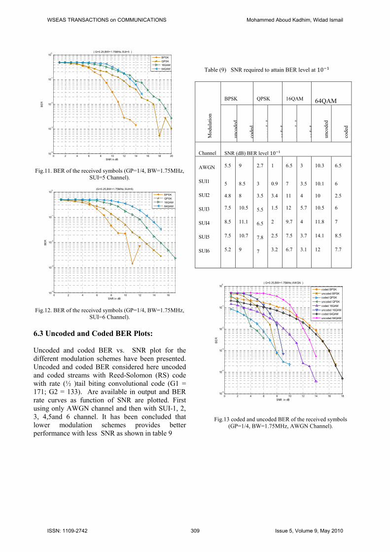
Fig.11. BER of the received symbols (GP=1/4, BW=1.75MHz,
SUI=5 Channel).
Fig.12. BER of the received symbols (GP=1/4, BW=1.75MHz,
SUI=6 Channel).
6.3 Uncoded and Coded BER Plots:
Uncoded and coded BER vs. SNR plot for the
different modulation schemes have been presented.
Uncoded and coded BER considered here uncoded
and coded streams with Reed-Solomon (RS) code
with rate (½ )tail biting convolutional code (G1 =
171; G2 = 133). Are available in output and BER
rate curves as function of SNR are plotted. First
using only AWGN channel and then with SUI-1, 2,
3, 4,5and 6 channel. It has been concluded that
lower modulation schemes provides better
performance with less SNR as shown in table 9
Table (9) SNR required to attain BER level at 10
Modu
lati
on
BPSK
QPSK
16QAM
64QAM
unco
ded
cod
ed
unco
ded
cod
ed
unco
ded
cod
ed
unco
ded
cod
ed
Channel SNR (dB) BER level 10
AWGN
SUI1
SUI2
SUI3
SUI4
SUI5
SUI6
5.5
5
4.8
7.5
8.5
7.5
5.2
9
8.5
8
10.5
11.1
10.7
9
2.7
3
3.5
5.5
6.5
7.8
7
1
0.9
3.4
1.5
2
2.5
3.2
6.5
7
11
12
9.7
7.5
6.7
3
3.5
4
5.7
4
3.7
3.1
10.3
10.1
10
10.5
11.8
14.1
12
6.5
6
2.5
6
7
8.5
7.7
Fig.13 coded and uncoded BER of the received symbols
(GP=1/4, BW=1.75MHz, AWGN Channel).
0 2 4 6 8 10 12 14 16 18 2010
-4
10-3
10-2
10-1
100
( G=0.25,BW=1.75MHz,SUI=5 )
SNR in dB
BER
BPSK
QPSK
16QAM
64QAM
0 2 4 6 8 10 12 14 1610
-4
10-3
10-2
10-1
100
(G=0.25,BW=1.75MHz,SUI=6)
SNR in dB
BER
BPSK
QPSK
16QAM
64QAM
0 2 4 6 8 10 12 14 16 1810
-5
10-4
10-3
10-2
10-1
100
( G=0.25,BW=1.75MHz,AWGN )
SNR in dB
BER
coded BPSK
uncoded BPSK
coded QPSK
uncoded QPSK
coded 16QAM
uncoded 16QAM
coded 64QAM
uncoded 64QAM
WSEAS TRANSACTIONS on COMMUNICATIONS Mohammed Aboud Kadhim, Widad Ismail
ISSN: 1109-2742 309 Issue 5, Volume 9, May 2010

Fig.14. coded and uncoded BER of the received symbols
(GP=1/4, BW=1.75MHz, SUI=1 Channel).
Fig.15. coded and uncoded BER of the received symbols
(GP=1/4, BW=1.75MHz, SUI=2 Channel).
Fig.16. coded and uncoded BER of the received symbols
(GP=1/4, BW=1.75MHz, SUI=3 Channel).
Fig.17. coded and uncoded BER of the received symbols
(GP=1/4, BW=1.75MHz, SUI=4 Channel).
Fig.18. coded and uncoded BER of the received symbols
(GP=1/4, BW=1.75MHz, SUI=5 Channel).
Fig.19. coded and uncoded BER of the received symbols
(GP=1/4, BW=1.75MHz, SUI=5 Channel).
0 2 4 6 8 10 12 14 16 1810
-5
10-4
10-3
10-2
10-1
100
( G=0.25,BW=1.75MHz,SUI=1 )
SNR in dB
BER
coded BPSK
uncoded BPSK
coded QPSK
uncoded QPSK
coded 16QAM
uncoded 16QAM
coded 64QAM
uncoded 64QAM
0 2 4 6 8 10 12 14 16 1810
-4
10-3
10-2
10-1
100
( G=0.25,BW=1.75MHz,SUI=2 )
SNR In dB
BER
coded BPSK
uncoded BPSK
uncoded QPSK
coded 16QAM
uncoded16QAM
coded 64QAM
uncoded 64QAM
coded QPSK
0 2 4 6 8 10 12 14 16 1810
-4
10-3
10-2
10-1
( G=0.25,BW=1.75MHz,SUI=3 )
SNR in dB
BER
coded BPSK
uncoded BPSK
coded QPSK
uncoded QPSK
coded 16QAM
uncoded 16QAM
coded 64QAM
uncoded 64QAM
0 2 4 6 8 10 1210
-5
10-4
10-3
10-2
10-1
100
( G=0.25,BW=1.75MHz,SUI=4 )
SNR in dB
BER
coded BPSK
uncoded BPSK
coded QPSK
uncoded QPSK
coded 16QAM
uncoded 16QAM
coded 64QAM
uncoded 64QAM
0 2 4 6 8 10 12 14 16 1810
-5
10-4
10-3
10-2
10-1
100
( G=0.25,BW=1.75MHz,SUI=5 )
SNR in dB
BER
coded BPSK
uncoded BPSK
coded QPSK
uncoded QPSK
coded 16QAM
uncoded 16QAM
coded 64QAM
uncode 64QAM
0 2 4 6 8 10 12 14 16 1810
-4
10-3
10-2
10-1
100
( G=0.25,BW=1.75MHz,SUI=6 )
SNR in dB
BER
coded BPSK
uncoded BPSK
coded QPSK
uncoded QPSK
coded 16QAM
coded 64QAM
uncoded 64QAM
uncoded16QAM
WSEAS TRANSACTIONS on COMMUNICATIONS Mohammed Aboud Kadhim, Widad Ismail
ISSN: 1109-2742 310 Issue 5, Volume 9, May 2010

7. Conclusions
The Small Form Factor (SFF), Software-Defined
Radio (SDR) Development Platform is a unique
new product that addresses the special, portable
SDR needs of the military, public safety, and
commercial markets. It was designed around the
latest DSP and FPGA technology – Lyrtech’s area
of expertise – as a low-cost, off-the-shelf, integrated
hardware and software development solution. The
DSP and FPGA of the SFF SDR Development
Platform are completely integrated to the model-
based design flow, which integrates MATLAB,
Simulink, and Real-Time Workshop from The
MathWorks. The SFF SCA Development Platform
optional package allows SCA waveform
development and implementation the key
contribution of this paper was the implementation of
the IEEE 802.16d PHY layer using MATLAB in
order to evaluate the PHY layer performance under
reference different channel model. The implemented
PHY layer supports all the modulation and coding
schemes as well as CP lengths defined in the
specification. To keep matters simple we avoided
doing oversampling of the data samples before
using the AWGN and different SUI channel model.
Though, that can be implemented by minor
modifications. On the receiver side. The developed
Simulator can be easily modified to implement new
features in order to enhance the PHY layer
performance. Simulation was the methodology used
to investigate the PHY layer performance. The
performance evaluation method was mainly
concentrated on the effect of channel coding on the
PHY layer. The overall system performance was
also evaluated under different channel conditions..
A key performance measure of a wireless
communication system is the BER the BER curves
were used to compare the performance of different
modulation and coding scheme used. The effects of
the FEC and interleaving were also evaluated in the
form of BER. These provided us with a
comprehensive evaluation of the performance of the
OFDM physical layer for different states of the
wireless channel.
References
1. Wireless MAN Group. IEEE standard for local
and metropolitan area networks. Technical Report
IEEE Std 802.16-2001, wirelessMAN.org, 2001.
Part 16, Air Interface for Fixed Broadband Wireless
Access Systems
2. Book, Jeffrey G.Andrews, Arunabha Ghosh,
Rias Muhamed, Fundamentals of WIMAX, Prentice
Hall Communications Engineering and Emerging
Technology Series.
3. Small Form Factor SDR Evaluation Module/
Development Platform User’sGuide
4. Math Works express, Target Language Compiler.
2002.
5. IEEE Standard for Local and metropolitan area
networks, “Part 16: Air Interface for Fixed
Broadband Wireless Access Systems, IEEE Std
802.16™-2004”, 1 Oct 2004.
6. Wireless MAN Group. IEEE standard for local
and metropolitan area networks. Technical Report
IEEE Std 802.16-2001, wirelessMAN.org, 2001.
Part 16, Air Interface for Fixed Broadband Wireless
Access Systems
7. R. Nee and R. Prasad, OFDM for Wireless
Multimedia Communications, Artech House, 2000
8. Bernard Sklar, “Digital Communications:
Fundamentals and Applications, 2nd
Edition,”
January 11, 2001
9. V. Erceg et. al, “An empirically based path loss
model for wireless channels in suburban
environments,” IEEE JSAC, vol. 17, no. 7, July
1999, pp. 12051211.
10.Fixed, nomadic, portable and mobile applications
for 802.162004and 802.16e WIMAX networks
11. V. Erceg, K.V.S. Hari, M.S. Smith, D.S. Baum
et al, “Channel Models for Fixed Wireless
Applications”, IEEE 802.16.3 Task Group
Contributions 2001, Feb. 01
WSEAS TRANSACTIONS on COMMUNICATIONS Mohammed Aboud Kadhim, Widad Ismail
ISSN: 1109-2742 311 Issue 5, Volume 9, May 2010