wong klan ann - ir.unimas.my position-force control (24 pgs).pdf · this project report presents a...
TRANSCRIPT
II1'I3RID POSITION/FORCE CONTROL
WONG KLAN ANN
Universiti Malaysia Sarawak 1999TJ
211 W872
w
BORANG PENYERAHAN TESIS
Judul: Hybrid Position/Force Control
SI? SI PI; NGA. IIAN: 1996/97
Saya Wong Kian Ann(HURUF BESAR)
mengaku membenarkan tesis ini disimpan di Pusat Khidmat Maklumat Akademik, Universiti Malaysia Sarawak dengan syarat-syaral kegunaan seperti herikut:
I .
Hakmilik kertas projek adalah di hawah nama penulis melainkan penulisan sehagai projck hersama dan dihiayai oleh UNIMAS, hakmiliknya adalah kepunyaan UNIMAS.
2. Naskhah salinan di dalam hentuk kertas atau mikro hanya holch dihuat dengan kehenaran hertulis daripada penulis.
3. Pusat Khidmat Maklumat Akademik. UNIMAS dihenarkan membuat salinan untuk pengajian mereka. 4. Kertas projek hanya holeh diterhitkan dengan kehenaran penulis. Bayaran royalti adalah mengikut kadar
yang dipersetujui kelak. 5. * Saya memhenarkan/tidak memhenarkan Perpustakaan membuat salinan kertas prgjek ini sebagai bahan
pertukaran di antara institusi pengajian tinggi. 6. ** Sila tandakan ( J )
I I
I
0
Alanwl Irlap:
SULIT
TERHAD
TIDAK TERHAD
I)isahkan olch
(TAN I) NG E: NULIS) (TANDATANGAN PENYELIA)
6, Jalan Pangsan 3,
Seksen 27/12 C,
Shah Alam, Selangor.Nama Pcayclia
Tarikh: 21 -11 -1998 Tarikh: 21-11-1998
CATATANkY
Potonk yang lidak bcrkcnaan.
. lika Kcrtus I'rojck ini SULIT atau TF. KHAU, sila lampirkan surat daripada pihak bcrkuasa/ orl; unisasi Ixrkcnaan dcnl; an mcnycrtakan sckali tempoh kcrtas projck. Ini pcrlu dikelaskan schauai Slll. l'1' atuu "I'IiKHAU.
(Mengandungi maklumat yang herdarjah keselamatan atau kepentingan Malaysia seperti yang termaktuh di dalam AKTA RAHSIA RASMI 1972).
(Mengandungi maklumat TERHAD yang telah ditentukan oleh organisasi/ hadan di mana penyclidikan dijalankan).
Mr. Andrew Ragai Henry Rigit
Approval Sheet
This project report attached hereto, entitle "Hybrid Position/Force Control" prepared
and submitted by WONG KIAN ANN in partial fulfilment of the requirements for
the degree of Bachelor of Engineering with honours in Mechanical Engineering and
Manufacturing Systems is hereby accepted.
Date:(Dr. Ha How Ung Head ProgrammeMechanical Engineering & Manufacturing Systems Faculty cif' Engineering Universiti Malaysia Sarawak
Pusat Khidmat Maklumat Akadlrrik UN[VERSITI MALAYSIA SARAit-, -XK
P. KHIDMAT MAKLUMAT UNIMAS
�III"0000078250
HYBRID POSITION/FORCE CONTROL
WONG KIAN ANN
Tesis Dikemukakan Kepada Fakulti Kejuruteraan, Universiti Malaysia Sarawak
Sebagai Memenuhi Sebahagian daripada Syarat penganugerahan Sarjana Muda Kejuruteraan
Dengan Kepujian (Kejuruteraan Mekanikal dan Sistem Pembuatan) Januari 1999
(
Dedicate to my beloved family.
My life will not be completed without them.
II
Acknowledgement
This project will not be successfully completed without the help from all parties.
The author would like to thank those parties that made a difference: Dr. Ha How
Ung, Head Programme of Mechanical Engineering and Manufacturing Systems, who
offered constant encouragement; Mr. Andrew R. H. Rigit, project supervisor, his
suggestions and criticisms of this project had a significant influence in the way the
material is presented in this report; Pass Group members, who contributed funds at a
critical juncture. Besides, the author would like to thank a very special friend,
Belinda Lip for her helpful comments and suggestions especially in the grammar
mistakes. Finally, the author would also like to thank his family especially K. B.
Wong, eldest brother, for his support and love. K. B. Wong died before this report
was completed. He will be missed by the author and those who were fortunate to
know him.
Abstract
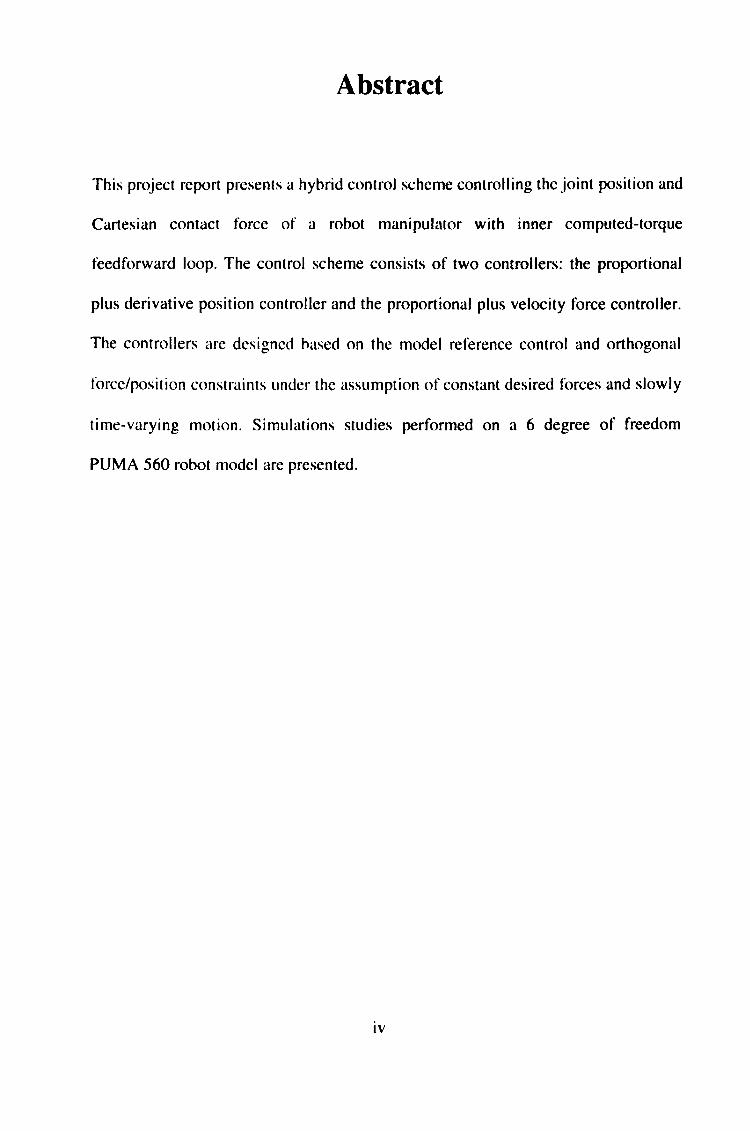
This project report presents a hybrid control scheme controlling the joint position and
Cartesian contact force of a robot manipulator with inner computed-torque
feedforward loop. The control scheme consists of two controllers: the proportional
plus derivative position controller and the proportional plus velocity force controller.
The controllers are designed based on the model reference control and orthogonal
force/position constraints under the assumption of constant desired forces and slowly
time-varying motion. Simulations studies performed on a 6 degree of freedom
PUMA 560 robot model are presented.
IV
Abstrak
Laporan project ini mempersemhahkan sejenis teknik kawalan gabungan yang
hertujuan mengawal gerakan tangan robot. Sistem kawalan ini terdiri daripada sistem
kawalan kedudukan rujukan sendi dan sistem kawalan daya sentuhan rujukan
Kartesian dengan hantuan loop suap-depan dalaman tork-berkomputcran. Sistem
kawalan ini mempunyai dua sub-sistem iaiatu: pengawal kedudukan jenis berkadaran
campur pemhezean; dan pengawal daya jenis berkadaran campur halaju. Kedua-dua
sub-sistem ini direkacipta berdasarkan konsep kawalan rujukan permodelan dan sifat
ketentangan daya dan kedudukan herorthogonal dengan angapan bahawa daya ialah
tetap dan gerakan adalah perlahan herhanding dengan masa. Simulasi komputer
dijalankan dengan hantuan model robot jenis PUMA 560 yang mempunyai enam
darjah gerakan bebas.
V
Puy at Khidmat t'N Makfumat Akademik iVERSITI MA[. AYSIA SARAWAK
Table of Contents
Dedication
Acknowledgement
Abstract
Abstrak
Table of Contents
List of Table
List of Algorithm
List of Figure
Chapter 1 Introduction
1.1 Robotics Technology
1.2 Today's Robot Application in Manufacturing
. 1.2. I Material Handling
1.2.2 Welding
1.2.3 Spray Painting/Coating
1.2.4 Packaging and Palletising
1.2.5 Water Jet Cutting
1.3 Future Robot Applications
1.4 Stiffness and Compliance
1.5 Project Objectives
Chapter 2 Theoretical Modelling
2.1 Object Location 2.1.1 Cartesian Co-ordinates
11. 2 Three Dimensional Translation and Orientation
Page
ii
III
iv
V
vi
IX
IX
X
3
3
4
7
I0
13
13
14
16
17
17
18
18
vi
2.2 Manipulator Kinematics 21
2.2. 1 Link Description 22
2.2.2 Forward Kinematics Equation 25
2.2.3 Manipulator Jacobian 27
2.3 Manipulator Rigid-Body Dynamics 29
2.3. 1 Joint Velocities of a Robot Manipulator 31
2.3.2 Kinetic Energy of a Robot Manipulator 35
2.3.3 Potential Energy of a Robot Manipulator 37
2.3.4 Motion Equation of a Manipulator 37
2.3.5 Cartesian Space Dynamic Formulation 39
2.4 PUMA 560 Model 41
2.4.1 Kinematics Model 41
2.4.2 Dynamics Model 47
Chapter 3 Force Control 3.1 Robot Control Technology
3.2 Force and Torque Sensing
3.2. 1 Elements of a Wrist Force Sensor
3.3 Natural and Artificial Constraints
3.4 Hybrid Position/Force Control
3.4. 1 Position Control Along a Single Degree-of-freedom
3.4.2 Force Control Along a Single Degree-of-freedom
3.4.3 Hybrid Position/Force Control Scheme
Chapter 4 Results and Discussions
4.1 Methodologies
4.2 Control Gains Tuning
4.2. 1 Position Gains Tuning
4.2.2 Force Gains Tuning
49
49
53
53
54
58
58
61
65
70
70
73
73
77
vii
4.3 Results 77
4.3. 1 Result 1: Tracking a Trajectory in Free Space 78
4.3.2 Result 2: Exerting a Force While in Contact with the
Environment 84
Chapter 5 Conclusions and Recommendations
Appendix A PUMA 560 Robot Parameters
Appendix B Result 1 Setting File
Appendix C Simulation File
Appendix D Result 2 Setting File
References
88
89
90
91
93
94
viii
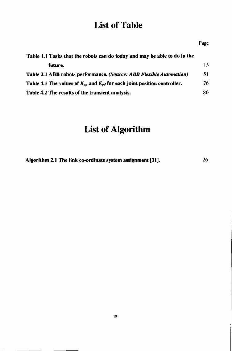
List of Table
Page
Table 1.1 Tasks that the robots can do today and may be able to do in the
future. 15
Table 3.1 ABB robots performance. (Source: ABB Flexible Automation) 51
Table 4.1 The values of Kp, and Kpd for each joint position controller. 76
Table 4.2 The results of the transient analysis. 80
List of Algorithm
Algorithm 2.1 The link co-ordinate system assignment [111. 26
IX
List of Figure
Page
Figure 1.1 ABB robot in material handling task. (Source: ABB Flexible
Automation) 4
Figure 1.2 Spot welding. (Source: ABB Flexible Automation) 6
Figure 1.3 Master-slave arc welding. (Source: ABB Flexible
Automation) 8
Figure 1.4 TR 5002. (Source: Aßß Flexible Automation) 9
Figure 1.5 Large working envelope. (Source: ABB Flexible
Automation) I 1
Figure 1.6 IRB 4400L10. (Source: ABB Flexible Automation) 12
Figure 2.1 Co-ordinate frame showing position directions of axes 19
according to the right-hand rule.
Figure 2.2 D-H notation of link co-ordinate system and its parameters. (Source: Robotics Toolbox Manual) 24
Figure 2.3 A point 'r; in link i. 33
Figure 2.4 Six degree of freedom PUMA 560 robot. 43
Figure 2.5 PUMA 560 link co-ordinate transformation matrices. 46
Figure 3.1 Wrist force sensor. 55
Figure 3.2 Manipulator in contact with the environment. 57
Figure 3.3 Mechanical model of a DC torque motor connected through
gearing to an inertial load. 60
Figure 3.4 A position control system for the single joint link. 62
Figure 3.5 Force and torque constraints for a single link rod. 63
Figure 3.6 A practical force control system for a single joint link. 66
Figure 3.7 Hybrid position/force control block diagram. 49
Figure 4.1 Robot/environment model used in the simulations. 72
Figure 4.2 Joint position step response. 79
Figure 4.3 The Cartesian co-ordinate for the trajectory. 82
Figure 4.4 Joint position for the trajectory. 83
X
Figure 4.5 The force step response. 86
Figure 4.6 Unstable initial contact force. 87
XI
Chapter 1
Introduction
This chapter describes briefly the active research fields in robotics technology. The
study of today's robot applications and future robot applications are compared. From
there, it is possible to identify the importance of implementing active compliant
motion robot controller to improve its accuracy and stability. Finally, the project
objectives are provided as a context for the detailed analysis of robot force control in
subsequent chapters.
1.1 Robotics Technology
The word 'robot' was first coined by the Czechoslovakian playwright Karel
Capek which means forced labour or serf [ 11. Since in our childhood we saw
robot cartoons and movies all around of us. In our mind, we often think of
robot as a human like machine that is able to move, talk, fight and even fly!
However, robot has a totally different meaning in the engineering world
especially in the industrial field. The Robot Institute of America has defined
robot as [21:
A programmable, multifunctional manipulator designed to move
material, parts, tools, or specialised devices through various
programmed motions for the performance of a variety of tasks.
I
From the above definition, a machine can he called a robot when it is able to
reprogram and do multifunctional manufacturing task. However, this
definition restricts robots to industrial applications only.
The study of robots is called `robotics'. The term was coined and first used by
the Russian born America scientist and writer Isaac Asimov [3]. When
discussing about robotic systems, there are plenty of different areas that could
be studied. Below are some major robotics field commonly see in reference
books, magazines and research journals:
1. Robot Mechanism Design - This area mostly discuss some issues
involving the design of the robot such as size, weight, speed and load
capability. Mobile robot has been a hot topic in recent researches [7].
2. Control of Robot - A controller is needed to control the robot according
to task specification. The issues involved in this field include stability,
accuracy, and reliability of the robot control system such as PID, CTM,
adaptive control, force control and etc. [4]. The present robot control
researches arc being in artificial intelligence, neural networks and fuzzy
systems.
3. Programming of Robot - To control the robot, the robot has to be taught
how to do the job. This lead to the development of robotics programming
language such as VAL from Unimation, AR-BASIC from American
Cimflex, and AML developed by IBM. The latest trend in robot
2
programming is Off-Line Programming Systems (OLP). OLP is defined as
a robot programming language which has been sufficiently extended,
generally by means of computer graphics, that the development of robot
programs can take place without access to the robot itself [5].
4. Robot Application - In this field, the study is concentrated in industrial
applications such as spot welding, spray painting, cutting, material
handling, and assembly. The future trends will be in flexible
manufacturing applications, bio-medical applications and multi-robot
systems.
1.2 Today's Robot Applications in Manufacturing
For more detail investigations of the today's industrial robot applications in
manufacturing, ABB robots were taken as a case study. ABB (Asian Brown
Boveri) is one of the leading industrial robot manufacturers in the world. First
ABB robot was introduced in 1974. ABB robots have been applied to various
industrial applications including:
I. Material Handling 4. Packaging and Palletising
2. Welding 5. Water Jet Cutting
3. Spray Painting/Coating
1.2.1 Material Handling
For material handling task, the robot needs to move to a prescribed location,
grasps an object, moves to a second prescribed location, and release the object
3
(see Figure I. 1). ABB robots are being actively applied in foundry industry
for the needs of flexibility, capability, and precision in handling both delicate
and heavy parts. One of the reasons robots used in foundry industry is to
reduce the hazards (heat, noise, fumes, and dust) exposure to the workers.
When using robots for foundry environment, some protections have to he
made including anti-rust coat on all unpainted parts; all bearings, joints and
cable-contacts are sealed; anti-dust strip above the controller cabinets' door.
1.2.2 Welding
Welding is a process that joints metals by fusing them. Spot welding and arc
welding are two major welding techniques that robots have been successfully
used. There are over 20,000 ABB robots installed in the body shops of the
world's leading car manufacturers.
1. Spot welding - Spot welding is a process in which two sheet metal parts
are fused together at localised points by passing a large electric current
through the parts where the weld is to be made. The electric current results
in sufficient heat in the contact area to fuse the two metal parts, hence
producing the weld. ABB robot - IRB 6400 has been specially design for
spot welding applications (see Figure 1.2). IRB 6400 robots have several
advanced capabilities including:
" Reweld and process-error routines.
" Multi-tasking functionality.
" High load offset capability.
4
--"'".. ""acaa 114RIUIIIJl HKauen1K kiN! VERSITI MALAYSIA SARAWAK
Figure 1.1 ABB robot in material handling task. (Source: ABB Flexible
Automation. )
5
Figure 1.2 Spot welding. (Source: ABB Flexible Automation. )
6
2. Arc welding - Arc welding is a continuous welding process. The process
uses an electrode in the form of a rod or wire of metal to supply the high
electric current (100 to 300 A) needed for establishing the arc. The arc
between the welding rod and the metal parts to be joined produces
temperatures that are sufficiently high to form a pool of molten metal to
fuse the two pieces together.
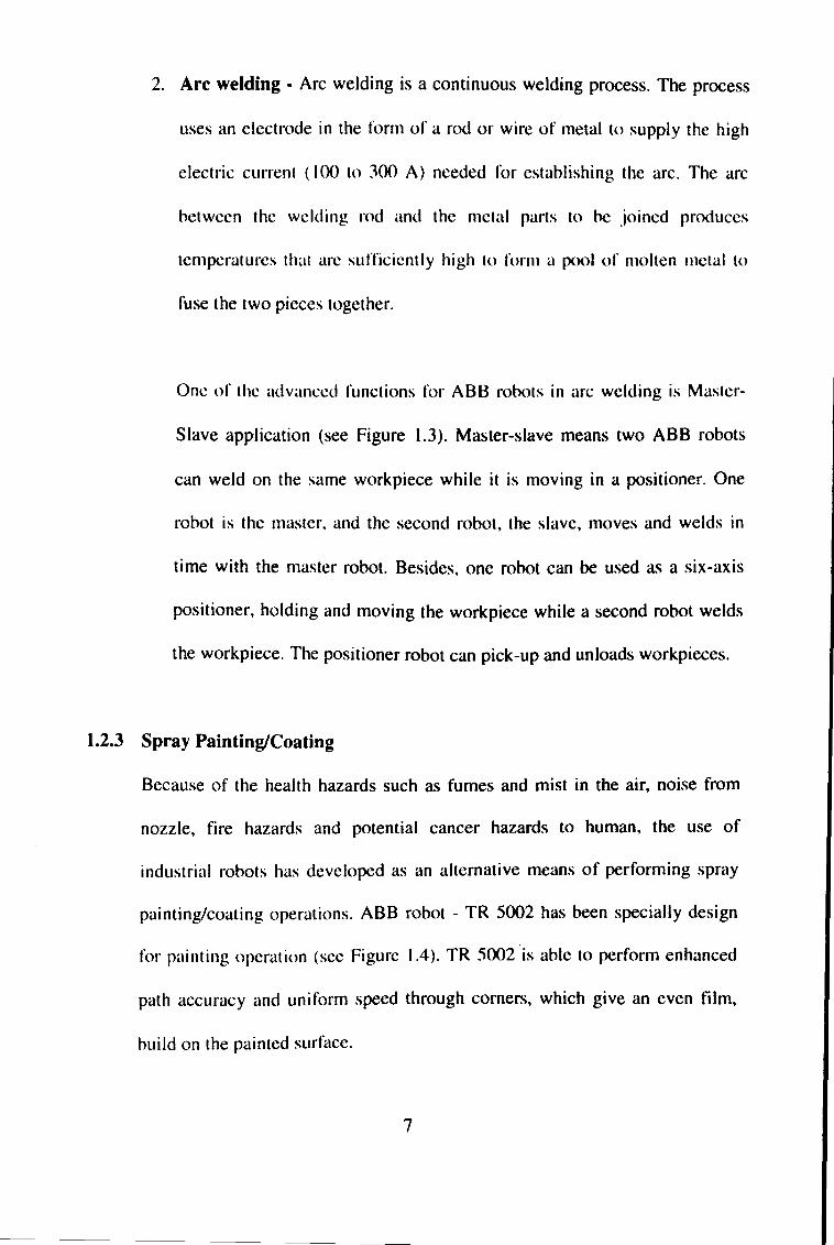
One of the advanced functions for ABB robots in arc welding is Master-
Slave application (see Figure 1.3). Master-slave means two ABB robots
can weld on the same workpiece while it is moving in a positioner. One
robot is the master, and the second robot, the slave, moves and welds in
time with the master robot. Besides, one robot can be used as a six-axis
positioner, holding and moving the workpiece while a second robot welds
the workpiece. The positioner robot can pick-up and unloads workpieces.
1.2.3 Spray Painting/Coating
Because of the health hazards such as fumes and mist in the air, noise from
nozzle, fire hazards and potential cancer hazards to human, the use of
industrial robots has developed as an alternative means of performing spray
painting/coating operations. ABB robot - TR 5002 has been specially design
for painting operation (see Figure 1.4). TR 5002 is able to perform enhanced
path accuracy and uniform speed through corners, which give an even film,
build on the painted surface.
7
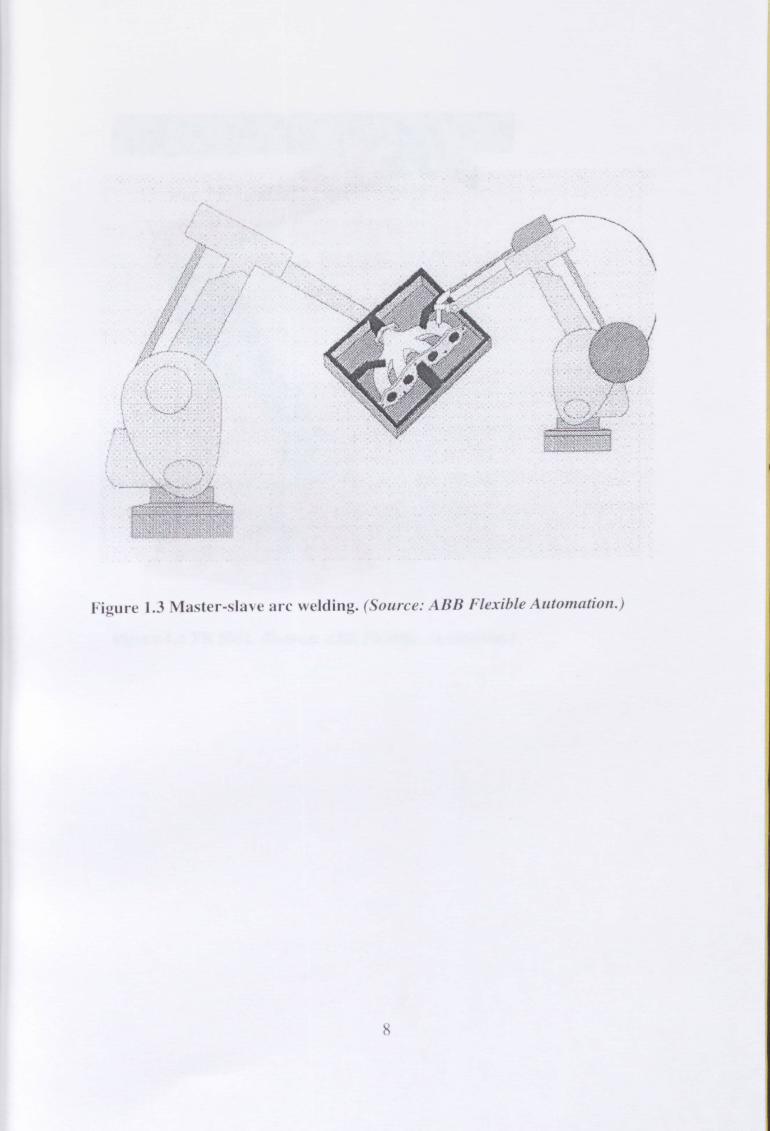
Figure 1.3 ylaster-slave arc welding. (Source: ABB Flexible Automation. )
Figure 1.4 TR 5002. (Source: ABB Flexible Automation. )
9
Besides, TR 5002 has a large working envelope shown in Figure 1.5.
ABB robot - IRB 4400LIO has been specially developed for sealing
application illustrated in Figure 1.6. IRB 440OLIO able to perform several
sealing processes involved:
I. Stone-ship coating. 3. Body-side coating.
2. Sealing. 4. Air blasting.
1.2.4 Packaging and Palletising
Frequent changes in packaging style and shape have become a key factor in
marketing consumer goods. A robot-based packaging line gives the flexibility
and reliability to meet these challenges. Operator safety, space and cost
savings are some principal features that can be gained in robotised packaging
applications, compared with dedicated packaging systems.
ABB robot - IRB 640 has been design specially to suit the palletising
operations. It is able to carry a payload up to 160 kg and having a high
productivity up to 1,200 cycles per hour. Bellow is some palletising operations
that can be done by IRB 640:
1. End-of-the-line palletising.
2. Middle-of-the-line palletising.
3. Complex-end-of-the-line palletising.
4. Palletising/depalletising station.
10