iiiii;lrrnlrljireprints.uthm.edu.my/id/eprint/702/1/24_pages_from... · jalan raya apabila menuju...
TRANSCRIPT

1111 IIIII;lrrnlrlJir !WIlli' 111111 "30000002103398"
SIMULATION OF PAVEMENT DEFORMATIONS FOR DIFFERENT APPROACH SLABS CONCEPT CONSTRUCTED
ON BATU PAHAT SOFT CLAY (BPSC)
MOHD NAZRIN MOHD DAUD
This dissertation is submitted as a fulfilment of the requirements for the award of
The Master Degree of Civil Engineering
Faculty of Civil and Environmental Engineering
Universiti Tun Hussein Onn Malaysia
MAY 2007
1£ ~JI
, rli~~
JUDUL:
Saya
UNIVERSITI TUN HUSSEIN ONN MALAYSIA
BORANG PENGESAHAN STATUS TESIS·
SIMULA TION OF PAVEMENT DEFORMATION FOR DIFFERENT
APPROACH SLABS CONCEPT CONSTRUCTED ON BATU PAHAT
SOFT CLAY
SESI PENGAJIAN: 2006/2007
MOHD NAZRIN BIN MOHD DAUD (HURUF BESAR)
mengaku membenarkan tesis (PSMISarjanaIDoktor Falsafah1* ini disimpan di Perpustakaan dengan syarat-syarat kegunaan seperti berikut:
1. Tesis adalah hakmilik Universiti Tun Hussein Onn Malaysia. 2. Perpustakaan dibenarkan membuat salinan untuk tujuan pengajian sahaja. 3. Perpustakaan dibenarkan membuat salinan tesis ini sebagai bahan pertukaran antara institusi
pengajian tinggi. 4. **SiIa Tandakan ( ,f)
D D
SULIT
TERHAD
(Mengandungi maklumat yang berdmjah keselamatan atau kepentingan Malaysia seperti yang termaktub di dalam AKT A RAHSIA RASMI 1972)
(Mengandungi maklumat TERHAD yang telah ditentukan oleh organisasilbadan dimana penyelidikan dijalankan)
[TI TIDAK TERHAD
Disahkan oleh,
(T ANDATANGAN PENYELIA) PROF. DR. !JOHD mnus HJ. MOHD MASIBlN
Alamat Tetap: Tinibalan Dekan <Penyf.',}.idikan &Pembangunan)
No. 75 A Jalan No.4, Kg. MehlYu Raya, 85000 Segamat, Johor.
Falrulti Kejuruternan Aviam & Alam 8ekitnr lJniverniti 'fun Hussein Onn Malaysia
P.M. DR. MOHD IDRUS B. MOHD MASIRIN (Nama Penyelia)
Tarikh:
CATATAN: * **
•
Tarikh:
Potong yang tidak berkenaan. Jika tesis ini SULIT atau TERHAD, sila lampirkan surat daripada pihak berkuasalorganisasi berkenaan dengan menyatakan sekali sebab dan tempoh tesis ini perlu dikelaskan sebagai SULIT atau TERHAD. Tesis dimaksudkan sebagai tesis bagi Ijazah Doktor Falsafah dan Sarjana secara penyelidikan,atau disertasi bagi pengajian secara kerja kursus dan penyelidikan, atau Laporan Projek Sarjana Muda (PSM).
11
"I acknowledge that I have read this dissertation and in my opinion it has fulfilled the
requirements in scope and quality for the award of the
Signature
Name of Supervisor
Date
Master of Engineering in Civil Engineering."
:~ ........ ? ...... . ASSOC. PROF. DR. MOHD 1DRUS B. MOHD MAS1RIN
10, 5 ~ '2..4!J'O?-PRO.R MJillYA DR. M:oIill IDRU8 HJ. MOHD MA.StRIN' Timbalan Dekan (Ponye).iclikan &Pembangunnn) Faiultl Kejuruternnn Awnm & Alam Sekitnr ~aiversiti Tun HuaBein Onn Mal.aysia
"I acknowledge that this thesis is my own except the extracts and summaries in
which they have been citied accordingly" .
Signature
Name of Writer
Date
. ~~ (/1-.......... ~.~ .... MO D NAZRIN BIN MOHD DAUD
7/5/2007
111
Special dedication to my beloved father and mother, Mr. Mohd Daud Kayat and Mrs. Hamsah Sandir, all family
members and friends. Thanks for all your valuable contributions, patience and love.
May Allah S. W T, The Almighty bless our every living days, Insyallah. ..
IV
v
Praise to be Allah, with the bless of His Almighty, this Projek Sarjana has
been successfully completed within the given time frame. I would like to take this
great opportunity to thank my project supervisor, Assoc. Prof. Dr. Mohd Idrus bin
Mohd Masirin, all the supporting lecturers and staff of FKAAS especially Assoc.
Prof. Dr. Kemas Ahmad Zarnhari, Mr. Felix Ling Ngeeh Leh, Mrs. Nursitihazlin, and
also the lab technicians, Mrs. Zamra, Mr. Amir Zaki, and Mr. Azuan. Only with His
blessing that brought them to support and guide me favourably in order to finish this
master project and my studies in Universiti Tun Hussein Onn Malaysia with success.
I would also like to convey my special thanks to my beloved parents, Mr.
Mohd Daud Kayat and Mrs. Hamsah Sandir, and all my family members for their
guidance and support throughout my studies. Only with your support and blessings, I
have managed to continue my study this far successfully.
Thank You.
VI
ABSTRACT
Depression or bump that occurs between end of bridge approach slab and
road pavement interface always arises a great concern among motorists. The
occurrence of the bump that motorist feel as they leaves or approaches the bridge is
caused by the differential settlement problem. This problem becomes more apparent
particularly over soft soil condition such in Batu Pahat district. Currently, there is no
guideline and specification provided by the Public Work Department in designing a
proper bridge approach model, which has exceptional transition toward road
pavement. The current conventional model used in many projects was reported to be
less effective since the problem is still noticeable and it requires regular maintenance
work when the problem reappears recurrently. Practically, it is clear that the problem
is still unresolved and this is due to the complexity of the design problem itselfthat
merge the structural and geotechnical perspectives in design. The studies on
simulation modelling for approach slab and road pavement design also have been
rare. It is essential since such design analysis, which is based on numerical analysis,
could have advantages in providing preliminary expected outcomes for the modelling
purpose. In conjunction to this matter, the modelling of several approach slab and
road pavement concepts have been successfully conducted to verify the result
expectancies using this approach in order to provide better understanding on the
recurrent problem.
Keywords: bump, bridge approach slab, differential settlement, soft soil, simulation
modelling
V11
ABSTRAK
Ketidakseragaman permukaan atau 'bonggol' yang berlaku di antara muka
hujung papakjulur bagijambatan danjalan raya kerap kali mengundang
kebimbangan penggunajalan raya. Kejadian tersebut yang dirasai oleh pengguna
jalan raya apabila menuju atau melewatijambatan adalah diakibatkan oleh masalah
prerbezaan pemendapan yang berlaku. Masalah tersebut menjadi lebih jelas apabila
melibatkan pembinaan di kawasan tanah lembut seperti di daerah Batu Pahat. Pada
ketika ini tiada garis panduan mahupun spesifikasi yang disediakan oleh J abatan
Kerja Raya dalam mereka bentuk papakjulur yang mampu menangani permasalahan
tersebut. Model konvensional yang digunapakai pada ketika ini dilaporkan kurang
efektifkerana permasalahan ini masih berulang serta memerlukan kerja
penyelenggaraan yang kerap. Secara praktikalnya adalahjelas bahawa permasalahan
ini masih belum dapat diselesaikan dan ini adalah disebabakan oleh kesukaran yang
dialami ketika mereka bentuk model di mana ia melibatkan gabungan pemahaman
daripada sudut kejuruteraan struktur dan geoteknik. Manakala kajian kaedah simulasi
dalam hal ini adalah jarang dilakukan dan tidak meluas. Analisis seperti ini yang
melibatkan analisis elemen terhingga adaIah berguna dan mempunyai kelebihan
dalam menyediakan platfom rekabentuk awal. Berikutan ini, rekabentuk beberapa
konsep papakjulur bagijambatan dan seksyenjalan raya telah dijalankan dengan
jayanya dalam penyelidikan simulasi ini bagi menjelaskanjangkaan keputusan
terhadap kajian, seterusnya memperolehi pemahaman yang lebih terhadap
permasalahan yang berulang ini.
Kata kunci: bonggol, papak julur bagi jambatan, perbezaan mendapan, tanah lembut,
simulasi
Vlll
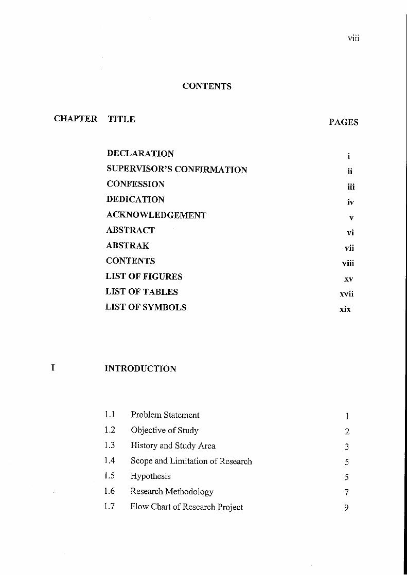
CONTENTS
CHAPTER TITLE PAGES
DECLARATION i SUPERVISOR'S CONFIRMATION ii CONFESSION iii DEDICATION iv ACKNOWLEDGEMENT v
ABSTRACT vi ABSTRAK vii CONTENTS viii LIST OF FIGURES xv LIST OF TABLES xvii LIST OF SYMBOLS xix
I INTRODUCTION
1.1 Problem Statement 1 1.2 Objective of Study 2 1.3 History and Study Area 3 1.4 Scope and Limitation of Research 5 1.5 Hypothesis 5 1.6 Research Methodology 7 1.7 Flow Chart of Research Project 9
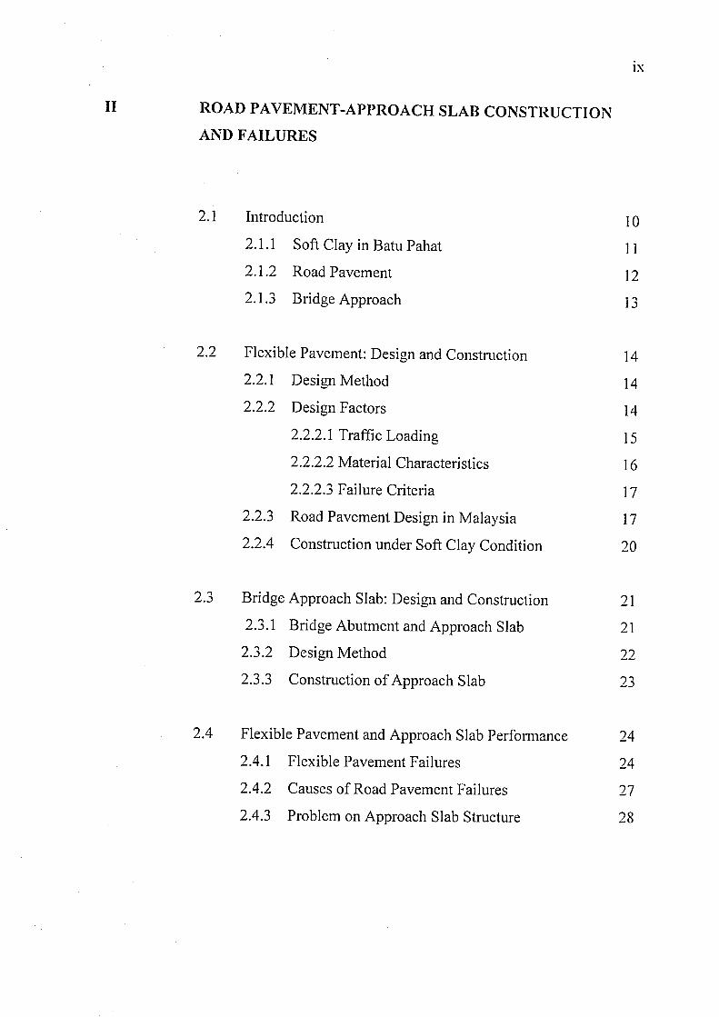
II ROAD PAVEMENT-APPROACH SLAB CONSTRUCTION AND FAILURES
2.1
2.2
2.3
2.4
Introduction
2.1.1 Soft Clay in Batu Pahat
2.1.2 Road Pavement
2.1.3 Bridge Approach
Flexible Pavement: Design and Construction
2.2.1 Design Method
2.2.2 Design Factors
2.2.2.1 Traffic Loading
2.2.2.2 Material Characteristics
2.2.2.3 Failure Criteria
2.2.3 Road Pavement Design in Malaysia
2.2.4 Construction under Soft Clay Condition
Bridge Approach Slab: Design and Construction
2.3.1 Bridge Abutment and Approach Slab
2.3.2 Design Method
2.3.3 Construction of Approach Slab
Flexible Pavement and Approach Slab Performance
2.4.1 Flexible Pavement Failures
2.4.2 Causes of Road Pavement Failures
2.4.3 Problem on Approach Slab Structure
IX
10 ] ]
]2
13
]4
14 14 15 16 17 17 20
21
21
22 ')" -j
24
24
27
28
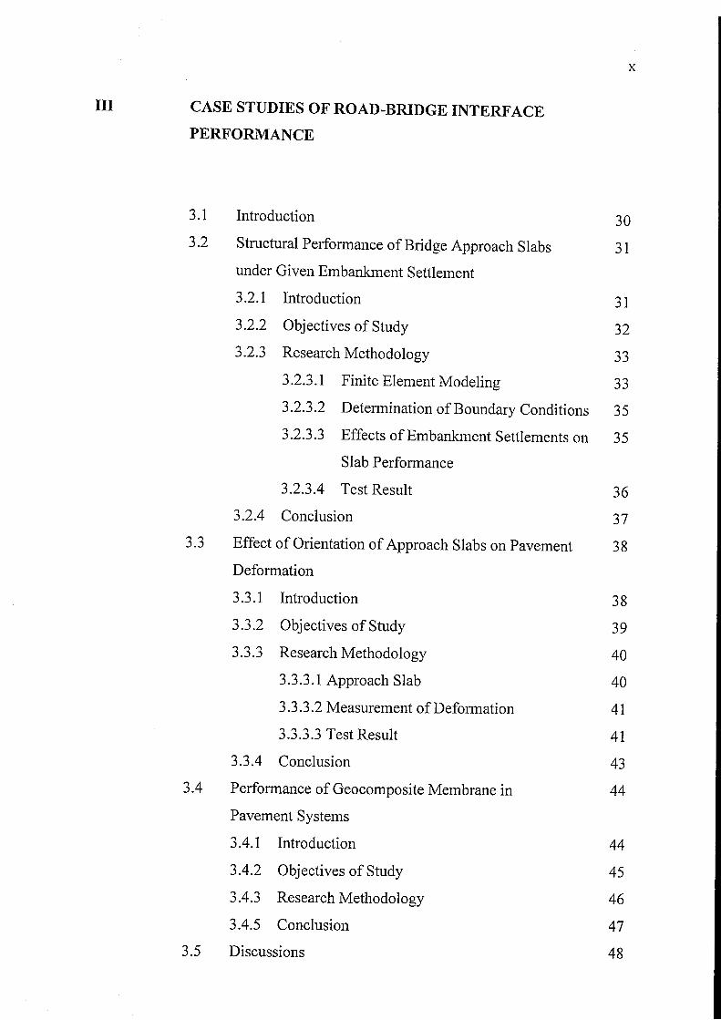
III CASE STUDIES OF ROAD-BRIDGE INTERFACE
PERFORMANCE
3.1 Introduction
3.2 Structural Performance of Bridge Approach Slabs
under Given Embankment Settlement
3.2.1 Introduction
3.2.2 Objectives of Study
3.2.3 Research Methodology
3.2.3.1 Finite Element Modeling
3.2.3.2 Determination of Boundary Conditions
3.2.3.3 Effects of Embankment Settlements on
Slab Performance
3.2.3.4 Test Result
3.2.4 Conclusion
3.3 Effect of Orientation of Approach Slabs on Pavement
Deformation
3.3.1 Introduction
3.3.2 Objectives of Study
3.3.3 Research Methodology
3.3.3.1 Approach Slab
3.3.3.2 Measurement of Deformation
3.3.3.3 Test Result
3.3.4 Conclusion
3.4 Performance of Geocomposite Membrane in
Pavement Systems
3.4.1 Introduction
3.4.2 Objectives of Study
3.4.3 Research Methodology
3.4.5 Conclusion
3.5 Discussions
x
30
31
31
32
33
33
35
35
36
37
38
38
39
40
40
41
41
43
44
44
45
46
47
48
Xl
IV FAILURE SIMULATION USING PLAXIS
4.1 Introduction 50 4.2 PLAXIS Finite Element Modelling in Geotechnics 51
4.2.1 Mohr-Coulomb Model 52 4.2.2 Soft-Soil Model 53 4.2.3 Soft-Soil-Creep Model 54
4.3 PLAXIS Programmes 55 4.3.1 Determination of Boundary Condition 56 4.3.2 Input Parameter 56
4.3.2.1 Geometrical Input 56 4.3.2.2 Loads Types 58 4.3.2.3 Material Input 58 4.3.2.4 Mesh Generation 60 4.3.2.5 Inital Condition 60
4.3.3 Calculation Program 61 4.3.3.1 Calculation Types 61 4.3.3.2 Loading Input 61 4.3.3.3 Calculation Phases 62 4.3.3.4 Selection of Points 63
4.3.4 Output Data 64 4.3.4.1 Graphical Output 64 4.3.4.2 Cross-Section Output 65 4.3.4.3 Table Output 66
4.3.5 Curve Generation 67 4.4 Failure Simulation Analysis 69 4.5 Limitation of PLAXIS Software 70
xu
v RESEARCH METHODOLOGY AND TESTING
5.0 Introduction 71 5.1 Gathering Data and Information 72
5.1.1 Literature Review 72 5.1.2 Interview 72
5.2 Field Investigation and Laboratory Testing 73 5.2.1 Geological Information of Study Area 73 5.2.2 Structural Condition 74 5.2.3 Sub ground Condition 75 5.2.4 Soil Testing 75
5.3 Traffic Loading 76 5.3.1 Type of Loading 77 5.3.2 Loading Configuration 78
5.4 Performing Simulation Program 78 5.4.4 Geometrical Parameters 79
5.4.4.1 Sub grade Thickness and Geotextile 79 Layer
5.4.4.2 Control Model (Horizontal Slab) 80 5.4.4.3 Slab Inclined at 5 to Horizontal 81 5.4.4.4 Phreatic Level 81
5.4.5 Material Parameters 82 5.4.6 Pavement Properties 83 5.4.7 Soil Properties 83 5.4.8 Concrete Slab Properties 84 5.4.9 Geosynthetic Properties 84
5.4.10 Determination of Boundary Conditions 84
XIII
VI DATA OBSERVATION AND ANALYSIS
6.1 Introduction 86 6.2 Consolidation Analysis on Transition Section 87
6.2.1 Horizontal Slab 87 6.2.2 5° Inclined Slab 90
6.3 Effect of SUbgrade Thickness and Reinforcement 92 on Defonnation Profiles
6.3.1 Horizontal Slab without Geosynthetic 93 Reinforcement
6.3.2 Horizontal Slab with Geosynthetic Reinforcement 94 6.3.3 Inclined Slab at 5° to Horizontal without 96
Geosynthetic Reinforcement
6.3.4 Inclined Slab at 5° to Horizontal with 97
Geosynthetic Reinforcement
6.4 Comparative Study on DefOlmation Profile of Different 98 Approach Slabs Design
6.5 Defonnation Analysis on Interface Region 101 6.6 Limitation of Research 103
VII CONCLUSION AND RECOMMENDATION
7.1 Introduction 106
7.2 Conclusion 107
7.2.1 The Application of PLAXIS Software in 107
Modelling Approach Slab Concept
7.2.2 Interface of Approach Slab and Flexible Road 108
Pavement
7.2.3 Perfonnance of 5° Inclined and Horizontal 109
Approach Slab Concept
7.3 Recommendations 110

RITTI~F\( r...;
.\1'1'1:\1)1(".",
,\
I ~
C PI ,\\1-"; ()"['''I' j).:, . •• ~ J ! ..;. ... ~ .
xv
LIST OF FIGURES
FIGURES NO. TITLE PAGES
1.1 Plan View of Study Area 4 1.2 Flow Chart of Research Project 9 2.1 State Roads in Batu Pahat District (Batu Pahat PWD, 2004) 19 2.2 Typical Cross Section of Rural Road Pavement in 20
Batu Pahat District (Public Work Department, 2001) 2.3 Typical Pavement Section Constructed on Parit Karjo State 21
Road (State Public Work Department, 2006) 2.4 Typical Rut on Flexible Road Pavement 26 2.5 Typical Fatigue Cracking on Road Pavement Surface 26
(Jestin, 2006)
3.1 Illustration of Slab Interaction with Soil (Cai, et. aI, 2005) 32 3.2 Sketch of Materials Arrangement (Cai, et, aI, 2005) 34 3.3 Deflection of Slab against Differential Settlement 36
(Cai, et. aI, 2005)
3.4 Rotation of Slab against Differential Settlement 36 (Cai, et. aI, 2005)
3.5 Test Section of the Control Horizontal Slab (Cai, et. aI, 2005) 40 3.6 Test Section of the Slab at 5° to Horizontal 40
(Wong, et. al 1994)
3.7 Test Section of the Slab at 10° to Horizontal 41 (Wong, et. aI, 1994)
3.8 Deformation Profile of the Control Horizontal Slab 42 (Wong, et. aI, 1994)
3.9 Deformation Profile of the Slab at 5° to Horizontal. 42
(Wong, et. aI, 1994)
XVI
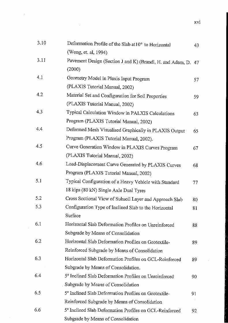
3.10 Deformation Profile of the Slab atl0° to Horizontal 43 (Wong, et. aI, 1994)
3.11 Pavement Design (Section J and K) (Brandl, H. and Adam, D. 47 (2000)
4.1 Geometry Model in Plaxis Input Program 57 (PLAXIS Tutorial Manual, 2002)
4.2 Material Set and Configuration for Soil Properties 59 (PLAXIS Tutorial Manual, 2002)
4.3 Typical Calculation Window in P ALXIS Calculations 63 Program (PLAXIS Tutorial Manual, 2002)
4.4 Deformed Mesh Visualised Graphically in PLAXIS Output 65 Program (PLAXIS Tutorial Manual, 2002).
4.5 Curve Generation Window in PLAXIS Curves Program 67 (pLAXIS Tutorial Manual, 2002)
4.6 Load-Displacement Curve Generated by PLAXIS Curves 68 Program (pLAXIS Tutorial Manual, 2002)
5.1 Typical Configuration of a Heavy Vehicle with Standard 77 18 kips (80 kN) Single Axle Dual Tyres
5.2 Cross Sectional View of Subsoil Layer and Approach Slab 80 5.3 Configuration Type of Inclined Slab to the Horizontal 81
Surface
6.1 Horizontal Slab Deformation Profiles on Umeinforced 88 Subgrade by Means of Consolidation
6.2 Horizontal Slab Deformation Profiles on Geotextile- 89
Reinforced Subgrade by Means of Consolidation
6.3 Horizontal Slab Deformation Profiles on GCL-Reinforced 89 Subgrade by Means of Consolidation.
6.4 5° Inclined Slab Deformation Profiles on Umeinforced 90
Sub grade by Means of Consolidation
6.5 5° Inclined Slab Deformation Profiles on Geotextile- 91
Reinforced Sub grade by Means of Consolidation
6.6 5° Inclined Slab Deformation Profiles on GCL-Reinforced 92
Sub grade by Means of Consolidation
XVII
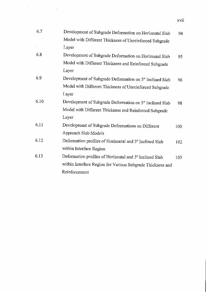
6.7 Development of Subgrade Deformation on Horizontal Slab 94 Model with Different Thickness of Umeinforced Subgrade Layer
6.8 Development of SUbgrade Deformation on Horizontal Slab 95 Model with Different Thickness and Reinforced Subgrade Layer
6.9 Development of SUbgrade Deformation on 5° Inclined Slab 96 Model with Different Thickness ofUmeinforced Subgrade
Layer
6.10 Development of Subgrade Deformation on 5° Inclined Slab 98 Model with Different Thickness and Reinforced Subgrade
Layer
6.11 Development of Subgrade Deformations on Different 100 Approach Slab Models
6.12 Deformation profiles of Horizontal and 5° Inclined Slab 102 within Interface Region
6.13 Deformation profiles of Horizontal and 5° Inclined Slab 103 within Interface Region for Various Subgrade Thickness and
Reinforcement
TABLES NO.
2.1
2.2
3.1
XVl11
LIST OF TABLES
TITLES PAGES
Roads Categories in Malaysia (Me or, et. aI, 2001) 18
Pavement Failures According to Several Researchers 25
(Jestin, 2006)
Material Parameters (Cai, et. aI, 2005) 34
AASHTO
CBR
CD
CU
DVL
FWD
EPS
ESAL
GCL
GPR
HPU
LaDOTD
NDT
NYDOT
PSI
PWD
u'
E
¢
u
c
LIST OF SYMBOLS
American Association of State Highway and
Transportation Officials
California Bearing Ratio
Consolidated Drained Test
Consolidated Undrained Test
Digital Video Logger
Falling Weight Deflectometer
Expanded Polystyrene
Equivalent Standard Load
Geosynthetic Clay Liner
Ground Penetrating Radar
Highway Planning Unit
XIX
Louisiana Department of Transportation Development
Non-Destructive Test
New York Department of Transportation
Present Serviceability Index
Public Work Department
normal stress
effective normal stress
confining pressure
modulus of elasticity
friction angle
deviator stress
pore pressure
cohesion
coefficient of consolidation
coefficient of secondary comporession
xx
f yield function
f function of the stress state
K* modified swelling/ recompression index A* modified compression index
Pp pre-consolidation stress
to time at which creep is assumed to commence
t) time
eo initial void ratio
e) void ratio
s shear stress
f-1* modified creep index
v Poission Ratio
If/ dilatancy angle
CHAPTER I
INTRODUCTION
1.1 Problem Statement
The concrete bridge found in Parit Karjo, Batu Pahat is constructed on deep
foundation pile which is structurally stable and sound. Construction of pavement and
bridge under soft soil circumstance is always linked to the differential settlement
problems between bridge abutments and roadway ends. Though, bridge approach
slab is provided to span across any difference in level due to settlement between the
bridge approach and the roadway ends. The long span concrete slab certainly will
provide smoother transition at the end of the roadways to the approach bridge. Thus,
providing better comfortability and rideability to commuters and road-users.
The occurrence of settlement for road pavements-bridge interface sections
will be noticeably when there is a sudden change of joint level between the ends of
paved roadway and constructed bridge approach slab. Undoubtedly, this will affect
the rideability quality or factor of the roadway in the long run. This complaint
involves a 'bump' that motorists feel as they are leaving or approaching the bridge.
The only alternative available now is rehabilitation or remedial work that is to