an investigation on printability of carbon nanotube …€¦ · · 2014-05-19an investigation on...
TRANSCRIPT
An Investigation on Printability of Carbon
Nanotube (CNTs) Inks by Flexographic onto
Various Substrates
M. I. Maksud, M. S. Yusof, Z. Embong, M. N. Nodin, and N. A. Rejab Universiti Tun Hussein Onn Malaysia, Batu Pahat, Johor, Malaysia
Email: {midris1973, azlinarejab88}@gmail.com, {mdsalleh, zaidi}@uthm.edu.my, [email protected]
Abstract—This paper work will be investigated the
printability of carbon nanotubes (CNT) conductive inks by
flexographic onto various substrates. Two types CNT which
are water and solvent base, and four types of substrates
which are silica, biaxially oriented polypropylene (BOPP),
70gms/m2 white blank office paper and woven had been
used. A pattern of multiple solid line of photopolymer
printing plate was prepared, with different width but
constant gaps width between 2 adjacent of lines. The
Printability of printing was checked visually. Simple test of
ink functional performance was checked by lighting up led
lamp. The roughness of the printed pattern surface was
determined by Atomic Force Microscopy (AFM). The result
showed that both inks can be printed under different
parameter setting. CNTs water base ink is the best ink
which can be printed onto many substrates but maintain
high electric conductivity.
Index Terms—flexographic, carbon nanotube (CNT),
surface morphology
I. INTRODUCTION
Conventional electronic, which with rigid components
and circuit boards have been around for decades and
served us in many important applications. However,
nowadays, printed electronics, which allows even roll to
roll (R2R) mass production on several flexible substrates
being a new opportunities explored by worldwide
researchers [1]-[4]. Components and circuits in printed
electronics, is printed by conventional printing methods
which familiar in graphic printing processes, like
flexographic, ink jet, screen printing, gravure and offset
lithographic. The most benefit of printed electronics are
enable to be printed onto various flexible substrate (for
providing smart or active function), mass production, low
cost, high productivity and an environmental friendly,
which can utilizes 90 percent of material usage compared
to conventional patterning employed in electronics such
photolithography or nano imprint lithography [5].
Therefore the main interests in using such printing
processes are high productivity and saving raw material.
Manuscript received January 1, 2014; revised March 4, 2014.
A. Flexographic
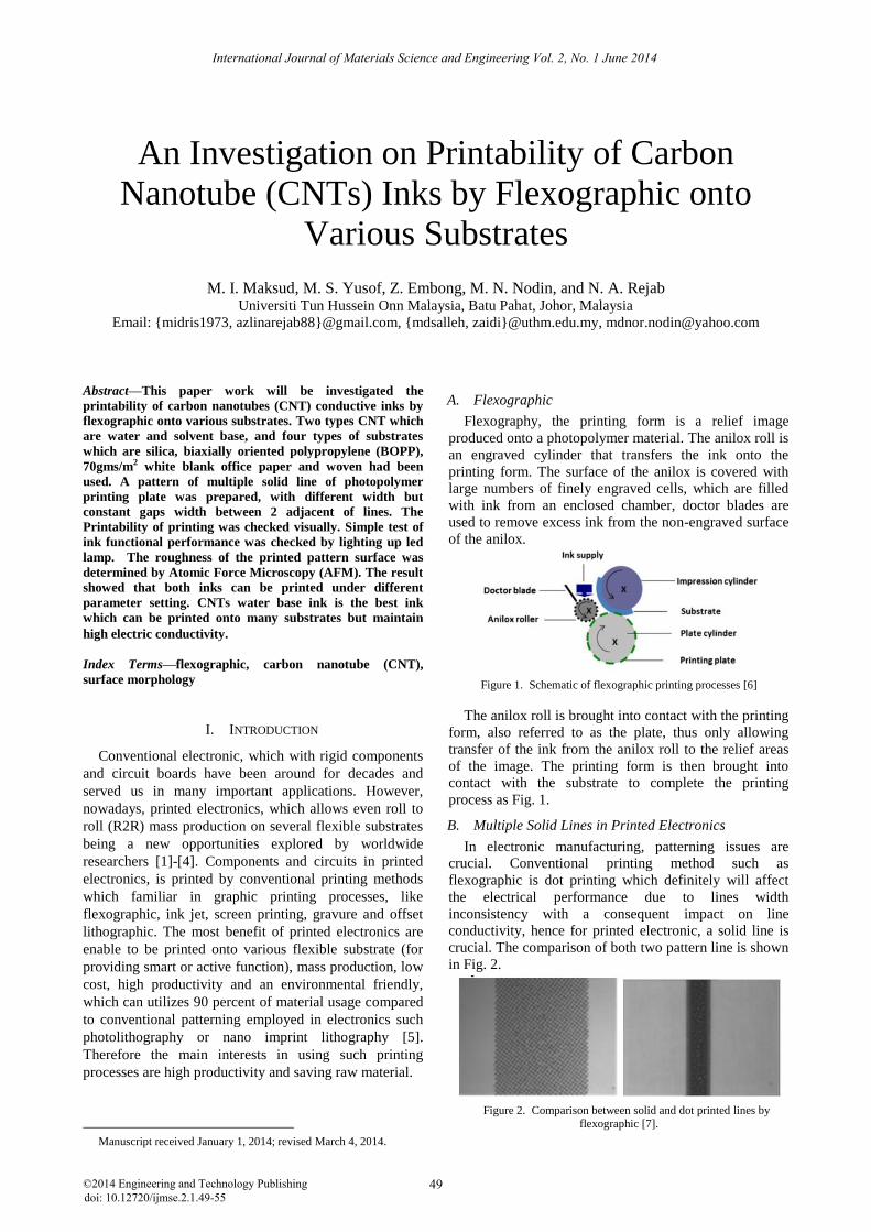
Flexography, the printing form is a relief image
produced onto a photopolymer material. The anilox roll is
an engraved cylinder that transfers the ink onto the
printing form. The surface of the anilox is covered with
large numbers of finely engraved cells, which are filled
with ink from an enclosed chamber, doctor blades are
used to remove excess ink from the non-engraved surface
of the anilox.
Figure 1. Schematic of flexographic printing processes [6]
The anilox roll is brought into contact with the printing
form, also referred to as the plate, thus only allowing
transfer of the ink from the anilox roll to the relief areas
of the image. The printing form is then brought into
contact with the substrate to complete the printing
process as Fig. 1.
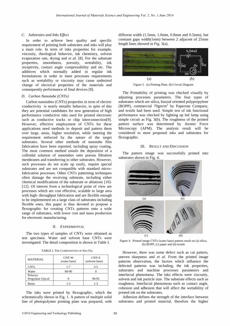
B. Multiple Solid Lines in Printed Electronics
In electronic manufacturing, patterning issues are
crucial. Conventional printing method such as
flexographic is dot printing which definitely will affect
the electrical performance due to lines width
inconsistency with a consequent impact on line
conductivity, hence for printed electronic, a solid line is
crucial. The comparison of both two pattern line is shown
in Fig. 2.
Figure 2. Comparison between solid and dot printed lines by flexographic [7].
International Journal of Materials Science and Engineering Vol. 2, No. 1 June 2014
©2014 Engineering and Technology Publishing 49doi: 10.12720/ijmse.2.1.49-55
C. Substrates and Inks Effect
In order to achieve best quality and specific
requirement of printing both substrates and inks will play
a main role. In term of inks properties for example,
viscosity, rheological behavior, ink chemistry, solvent
evaporation rate, drying and et al. [8]. For the substrate
properties, smoothness, porosity, wettability, ink
receptivity, contact angle compressibility and etc. The
additives which normally added in regular ink
formulations in order to meet processes requirements
such as wettability or viscosity may cause undesired
change of electrical properties of the materials and
consequently performance of final devices [8].
D. Carbon Nanotube (CNTs)
Carbon nanotubes (CNTs) properties in term of electric
conductivity is nearly metallic behavior, in spite of this
they are potential candidates for new generation of high
performance conductive inks used for printed electronic
such as conductive tracks or chip interconnection[9].
However, effective employment of CNTs for these
applications need methods to deposit and pattern them
over large, areas, higher resolution, while meeting the
requirement enforced by the nature of the target
substrates. Several other methods of nanotube film
fabrication have been reported, including spray coating.
The most common method entails the deposition of a
colloidal solution of nanotubes onto porous filtration
membranes and transferring to other substrates. However,
such processes do not scale up easily, require special
substrates and are not compatible with standard micro-
fabrication processes. Other CNTs patterning techniques
often damage the receiving substrate, including either
chemical modifications of the substrate or ablations [10]-
[12]. Of interest from a technological point of view are
processes which are cost effective, scalable to large area
with high- throughput fabrication and are flexible enough
to be implemented on a large class of substrates including
flexible ones, this paper is thus devoted to propose a
flexographic for creating CNTs patterns onto a wide
range of substrates, with lower cost and mass production
for electronic manufacturing.
II. EXPERIMENTAL
The two types of samples of CNTs were obtained as
test specimen. Water and solvent base CNTs were
investigated. The detail composition is shown in Table I.
TABLE I. THE COMPOSITION OF INK (%)
MATERIAL CNT-W
(water base) CNT-S
(solvent base)
CNTs 1-7 3-5
Water 80-90 0
Polyoxy Propylene Glycol 0 90-95
Resin 1-5 1-3
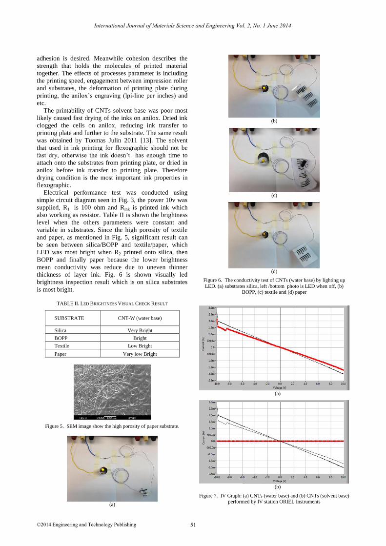
The inks were printed by flexographic, which the
schematically shown in Fig. 1. A pattern of multiple solid
line of photopolymer printing plate was prepared, with
different width (1.5mm, 1.0mm, 0.8mm and 0.5mm), but
constant gaps width(1mm) between 2 adjacent of 25mm
length lines showed in Fig. 3(a).
(a) (b)
Figure 3. (a) Printing Plate, (b) Circuit Diagram
The Printability of printing was checked visually by
adjusting processes parameters. The four types of
substrates which are silica, biaxial oriented polypropylene
(BOPP), commercial 70gm/m2 by Paperone Company,
and textile had been used. Simple test of ink functional
performance was checked by lighting up led lamp using
simple circuit as Fig. 3(b). The roughness of the printed
pattern surface was determined by Atomic Force
Microscopy (AFM). The analysis result will be
considered to most proposed inks and substrates for
flexographic.
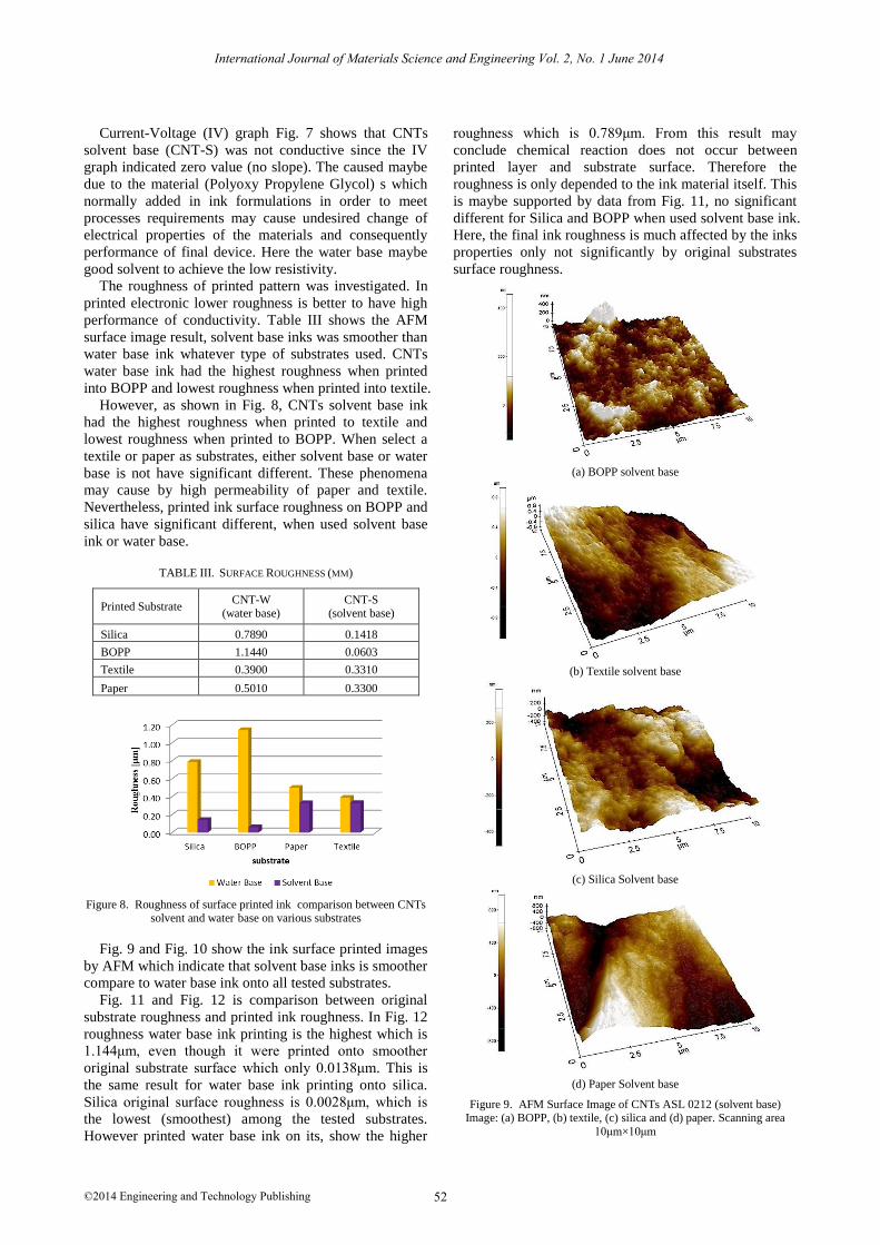
III. RESULT AND DISCUSSION
The pattern image was successfully printed into
substrates shown in Fig. 4.
(a) (b)
(c) (d)
Figure 4. Printed image CNTs (water base) pattern result on (a) silica, (b) BOPP, (c) paper and (d) textile
However, there was some defect such as cut pattern,
uneven sharpness and et al. From the printed image
patterns observation, the factors which influence the
defected patterns was including, the ink properties,
substrates and machine processes parameters and
interfacial phenomena. The inks effects were viscosity,
solvent and ink particle size. The substrate effects such as
roughness. Interfacial phenomena such as contact angle,
cohesion and adhesion that will affect the wettability of
printed ink on the substrates.
Adhesion defines the strength of the interface between
substrates and printed material, therefore the higher
International Journal of Materials Science and Engineering Vol. 2, No. 1 June 2014
©2014 Engineering and Technology Publishing 50
adhesion is desired. Meanwhile cohesion describes the
strength that holds the molecules of printed material
together. The effects of processes parameter is including
the printing speed, engagement between impression roller
and substrates, the deformation of printing plate during
printing, the anilox’s engraving (lpi-line per inches) and
etc.
The printability of CNTs solvent base was poor most
likely caused fast drying of the inks on anilox. Dried ink
clogged the cells on anilox, reducing ink transfer to
printing plate and further to the substrate. The same result
was obtained by Tuomas Julin 2011 [13]. The solvent
that used in ink printing for flexographic should not be
fast dry, otherwise the ink doesn’t has enough time to
attach onto the substrates from printing plate, or dried in
anilox before ink transfer to printing plate. Therefore
drying condition is the most important ink properties in
flexographic.
Electrical performance test was conducted using
simple circuit diagram seen in Fig. 3, the power 10v was
supplied, R1 is 100 ohm and Rink is printed ink which
also working as resistor. Table II is shown the brightness
level when the others parameters were constant and
variable in substrates. Since the high porosity of textile
and paper, as mentioned in Fig. 5, significant result can
be seen between silica/BOPP and textile/paper, which
LED was most bright when R2 printed onto silica, then
BOPP and finally paper because the lower brightness
mean conductivity was reduce due to uneven thinner
thickness of layer ink. Fig. 6 is shown visually led
brightness inspection result which is on silica substrates
is most bright.
TABLE II. LED BRIGHTNESS VISUAL CHECK RESULT
SUBSTRATE CNT-W (water base)
Silica Very Bright
BOPP Bright
Textile Low Bright
Paper Very low Bright
Figure 5. SEM image show the high porosity of paper substrate.
(a)
(b)
(c)
(d)
Figure 6. The conductivity test of CNTs (water base) by lighting up LED. (a) substrates silica, left /bottom photo is LED when off, (b)
BOPP, (c) textile and (d) paper
(a)
(b)
Figure 7. IV Graph: (a) CNTs (water base) and (b) CNTs (solvent base) performed by IV station ORIEL Instruments
International Journal of Materials Science and Engineering Vol. 2, No. 1 June 2014
©2014 Engineering and Technology Publishing 51
Current-Voltage (IV) graph Fig. 7 shows that CNTs
solvent base (CNT-S) was not conductive since the IV
graph indicated zero value (no slope). The caused maybe
due to the material (Polyoxy Propylene Glycol) s which
normally added in ink formulations in order to meet
processes requirements may cause undesired change of
electrical properties of the materials and consequently
performance of final device. Here the water base maybe
good solvent to achieve the low resistivity.
The roughness of printed pattern was investigated. In
printed electronic lower roughness is better to have high
performance of conductivity. Table III shows the AFM
surface image result, solvent base inks was smoother than
water base ink whatever type of substrates used. CNTs
water base ink had the highest roughness when printed
into BOPP and lowest roughness when printed into textile.
However, as shown in Fig. 8, CNTs solvent base ink
had the highest roughness when printed to textile and
lowest roughness when printed to BOPP. When select a
textile or paper as substrates, either solvent base or water
base is not have significant different. These phenomena
may cause by high permeability of paper and textile.
Nevertheless, printed ink surface roughness on BOPP and
silica have significant different, when used solvent base
ink or water base.
TABLE III. SURFACE ROUGHNESS (ΜM)
Printed Substrate CNT-W
(water base)
CNT-S
(solvent base)
Silica 0.7890 0.1418
BOPP 1.1440 0.0603
Textile 0.3900 0.3310
Paper 0.5010 0.3300
Figure 8. Roughness of surface printed ink comparison between CNTs solvent and water base on various substrates
Fig. 9 and Fig. 10 show the ink surface printed images
by AFM which indicate that solvent base inks is smoother
compare to water base ink onto all tested substrates.
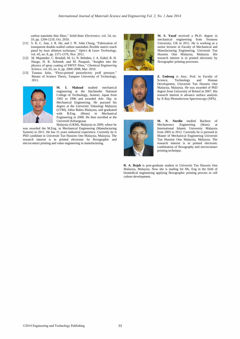
Fig. 11 and Fig. 12 is comparison between original
substrate roughness and printed ink roughness. In Fig. 12
roughness water base ink printing is the highest which is
1.144μm, even though it were printed onto smoother
original substrate surface which only 0.0138μm. This is
the same result for water base ink printing onto silica.
Silica original surface roughness is 0.0028μm, which is
the lowest (smoothest) among the tested substrates.
However printed water base ink on its, show the higher
roughness which is 0.789μm. From this result may
conclude chemical reaction does not occur between
printed layer and substrate surface. Therefore the
roughness is only depended to the ink material itself. This
is maybe supported by data from Fig. 11, no significant
different for Silica and BOPP when used solvent base ink.
Here, the final ink roughness is much affected by the inks
properties only not significantly by original substrates
surface roughness.
(a) BOPP solvent base
(b) Textile solvent base
(c) Silica Solvent base
(d) Paper Solvent base
Figure 9. AFM Surface Image of CNTs ASL 0212 (solvent base) Image: (a) BOPP, (b) textile, (c) silica and (d) paper. Scanning area
10μm×10μm
International Journal of Materials Science and Engineering Vol. 2, No. 1 June 2014
©2014 Engineering and Technology Publishing 52
(a) BOPP water base
(b) Textile water base
(c) Silica water base
(d) Paper water base
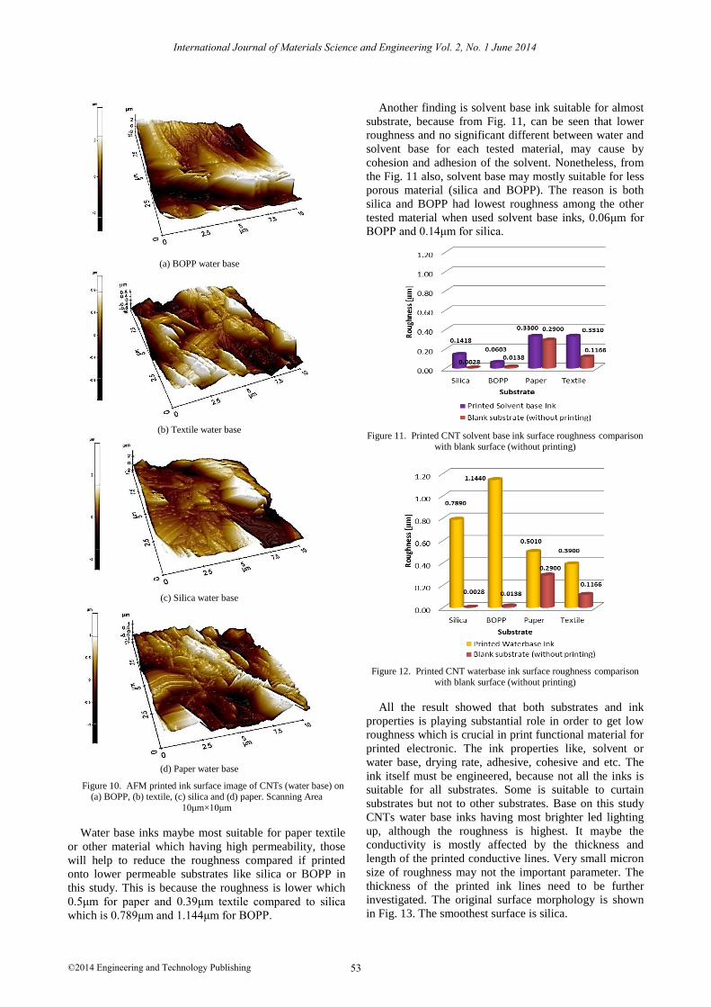
Figure 10. AFM printed ink surface image of CNTs (water base) on (a) BOPP, (b) textile, (c) silica and (d) paper. Scanning Area
10μm×10μm
Water base inks maybe most suitable for paper textile
or other material which having high permeability, those
will help to reduce the roughness compared if printed
onto lower permeable substrates like silica or BOPP in
this study. This is because the roughness is lower which
0.5μm for paper and 0.39μm textile compared to silica
which is 0.789μm and 1.144μm for BOPP.
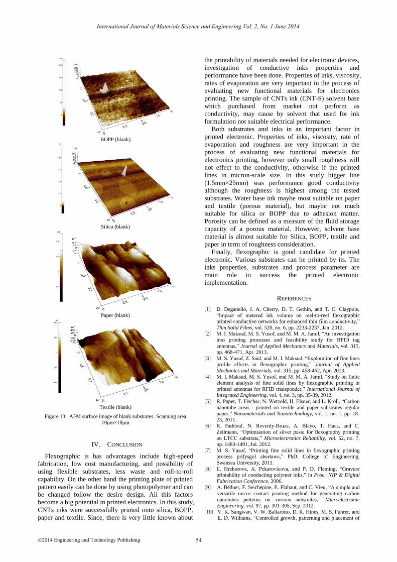
Another finding is solvent base ink suitable for almost
substrate, because from Fig. 11, can be seen that lower
roughness and no significant different between water and
solvent base for each tested material, may cause by
cohesion and adhesion of the solvent. Nonetheless, from
the Fig. 11 also, solvent base may mostly suitable for less
porous material (silica and BOPP). The reason is both
silica and BOPP had lowest roughness among the other
tested material when used solvent base inks, 0.06μm for
BOPP and 0.14μm for silica.
Figure 11. Printed CNT solvent base ink surface roughness comparison with blank surface (without printing)
Figure 12. Printed CNT waterbase ink surface roughness comparison with blank surface (without printing)
All the result showed that both substrates and ink
properties is playing substantial role in order to get low
roughness which is crucial in print functional material for
printed electronic. The ink properties like, solvent or
water base, drying rate, adhesive, cohesive and etc. The
ink itself must be engineered, because not all the inks is
suitable for all substrates. Some is suitable to curtain
substrates but not to other substrates. Base on this study
CNTs water base inks having most brighter led lighting
up, although the roughness is highest. It maybe the
conductivity is mostly affected by the thickness and
length of the printed conductive lines. Very small micron
size of roughness may not the important parameter. The
thickness of the printed ink lines need to be further
investigated. The original surface morphology is shown
in Fig. 13. The smoothest surface is silica.
International Journal of Materials Science and Engineering Vol. 2, No. 1 June 2014
©2014 Engineering and Technology Publishing 53
BOPP (blank)
Silica (blank)
Paper (blank)
Textile (blank)
Figure 13. AFM surface image of blank substrates. Scanning area 10μm×10μm
IV. CONCLUSION
Flexographic is has advantages include high-speed
fabrication, low cost manufacturing, and possibility of
using flexible substrates, less waste and roll-to-roll
capability. On the other hand the printing plate of printed
pattern easily can be done by using photopolymer and can
be changed follow the desire design. All this factors
become a big potential in printed electronics. In this study,
CNTs inks were successfully printed onto silica, BOPP,
paper and textile. Since, there is very little known about
the printability of materials needed for electronic devices,
investigation of conductive inks properties and
performance have been done. Properties of inks, viscosity,
rates of evaporation are very important in the process of
evaluating new functional materials for electronics
printing. The sample of CNTs ink (CNT-S) solvent base
which purchased from market not perform as
conductivity, may cause by solvent that used for ink
formulation not suitable electrical performance.
Both substrates and inks in an important factor in
printed electronic. Properties of inks, viscosity, rate of
evaporation and roughness are very important in the
process of evaluating new functional materials for
electronics printing, however only small roughness will
not effect to the conductivity, otherwise if the printed
lines in micron-scale size. In this study bigger line
(1.5mm×25mm) was performance good conductivity
although the roughness is highest among the tested
substrates. Water base ink maybe most suitable on paper
and textile (porous material), but maybe not much
suitable for silica or BOPP due to adhesion matter.
Porosity can be defined as a measure of the fluid storage
capacity of a porous material. However, solvent base
material is almost suitable for Silica, BOPP, textile and
paper in term of roughness consideration.
Finally, flexographic is good candidate for printed
electronic. Various substrates can be printed by its. The
inks properties, substrates and process parameter are
main role to success the printed electronic
implementation.
REFERENCES
[1] D. Deganello, J. A. Cherry, D. T. Gethin, and T. C. Claypole,
“Impact of metered ink volume on reel-to-reel flexographic printed conductive networks for enhanced thin film conductivity,”
Thin Solid Films, vol. 520, no. 6, pp. 2233-2237, Jan. 2012. [2] M. I. Maksud, M. S. Yusof, and M. M. A. Jamil, “An investigation
into printing processes and feasibility study for RFID tag
antennas,” Journal of Applied Mechanics and Materials, vol. 315, pp. 468-471, Apr. 2013.
[3] M. S. Yusof, Z. Said, and M. I. Maksud, “Exploration of fine lines profile effects in flexographic printing,” Journal of Applied
Mechanics and Materials, vol. 315, pp. 458-462, Apr. 2013.
[4] M. I. Maksud, M. S. Yusof, and M. M. A. Jamil, “Study on finite
element analysis of fine solid lines by flexographic printing in
printed antennas for RFID transponder,” International Journal of Integrated Engineering, vol. 4, no. 3, pp. 35-39, 2012.
[5] R. Paper, T. Fischer, N. Wetzold, H. Elsner, and L. Kroll, “Carbon
nanotube areas - printed on textile and paper substrates regular paper,” Nanomaterials and Nanotechnology, vol. 1, no. 1, pp. 18-
23, 2011. [6] R. Faddoul, N. Reverdy-Bruas, A. Blayo, T. Haas, and C.
Zeilmann, “Optimisation of silver paste for flexography printing
on LTCC substrate,” Microelectronics Reliability, vol. 52, no. 7, pp. 1483-1491, Jul. 2012.
[7] M. S. Yusof, “Printing fine solid lines in flexographic printing process prifysgol abertawe,” PhD. College of Engineering,
Swansea University, 2011.
[8] E. Hrehorova, A. Pekarovicova, and P. D. Fleming, “Gravure printability of conducting polymer inks,” in Proc. NIP & Digital
Fabrication Conference, 2006. [9] A. Béduer, F. Seichepine, E. Flahaut, and C. Vieu, “A simple and
versatile micro contact printing method for generating carbon
nanotubes patterns on various substrates,” Microelectronic Engineering, vol. 97, pp. 301-305, Sep. 2012.
[10] V. K. Sangwan, V. W. Ballarotto, D. R. Hines, M. S. Fuhrer, and E. D. Williams, “Controlled growth, patterning and placement of
International Journal of Materials Science and Engineering Vol. 2, No. 1 June 2014
©2014 Engineering and Technology Publishing 54
carbon nanotube thin films,” Solid-State Electronics, vol. 54, no. 10, pp. 1204-1210, Oct. 2010.
[11] S. K. C. Jian, J. R. Ho, and J. W. John Cheng, “Fabrication of
transparent double-walled carbon nanotubes flexible matrix touch panel by laser ablation technique,” Optics & Laser Technology,
vol. 43, no. 8, pp. 1371-1376, Nov. 2011. [12] M. Majumder, C. Rendall, M. Li, N. Behabtu, J. A. Eukel, R. H.
Hauge, H. K. Schmidt, and M. Pasquali, “Insights into the
physics of spray coating of SWNT films,” Chemical Engineering Science, vol. 65, no. 6, pp. 2000-2008, Mar. 2010.
[13] Toumas Julin, “Flexo-printed piezoelectric pvdf pressure,” Master of Science Thesis, Tampere University of Technology,
2011.
M. I. Maksud studied mechanical
engineering at the Hachinohe National College of Technology, Aomori, Japan from
1992 to 1996 and awarded Adv. Dip. in
Mechanical Engineering. He pursued his degree at the Universiti Teknologi Malaysia
(UTM), Johor Bahru Malaysia, and graduated with B.Eng. (Hons) in Mechanical
Engineering in 2008. He then enrolled at the
Universiti Kebangsaan Malaysia (UKM), Malaysia in 2009, where he
was awarded the M.Eng. in Mechanical Engineering (Manufacturing System) in 2011. He has 15 years industrial experience. Currently he is
PhD candidate in Universiti Tun Hussien Onn Malaysia, Malaysia. The
research interest is in printed electronic by flexographic and microcontact printing and value engineering in manufacturing.
M. S. Yusof received a Ph.D. degree in mechanical engineering from Swansea
University, UK in 2011. He is working as a
senior lecturer in Faculty of Mechanical and Manufacturing Engineering, Universiti Tun
Hussein Onn Malaysia, Malaysia. His research interest is in printed electronic by
flexographic printing processes.
Z. Embong is Assc. Prof. in Faculty of
Science, Technology and Human
Development, Universiti Tun Hussein Onn Malaysia, Malaysia. He was awarded of PhD
degree from University of Bristol in 2007. His research interest is advance surface analysis
by X-Ray Photoelectron Spectroscopy (XPS).
M. N. Nordin studied Bacheor of Mechatroncs Engineering (Hons) at
International Islamic University Malaysia from 2005 to 2012. Currently he is pursued in
Master of Mechanical Engineering Universiti
Tun Hussien Onn Malaysia, Malaysia. The research interest is in printed electronic
combination of flexography and microcontact printing technique.
R. A. Rejab is post-graduate student in Universiti Tun Hussein Onn Malaysia, Malaysia. Now she is studing for Ms. Eng in the field of
biomedical engineering applying flexographic printing process in cell
culture development.
International Journal of Materials Science and Engineering Vol. 2, No. 1 June 2014
©2014 Engineering and Technology Publishing 55