experimental investigation on shear capacity of reinforced
TRANSCRIPT
Vol. 3, No. 7 Modern Applied Science
86
Experimental Investigation on Shear Capacity of Reinforced Concrete Precracked Push-off Specimens with Externally Bonded Bi-Directional
Carbon Fibre Reinforced Polymer Fabrics
J. Jayaprakash (Corresponding author) School of Civil Engineering, Universiti Sains Malaysia
14300, Nibong Tebal, Seberang Perai Selatan, Pulau Pinang, Malaysia E-mail: [email protected], [email protected]
Abdul Aziz Abdul Samad
Faculty of Civil and Environmental Engineering, Universiti Tun Hussein On n Malaysia, Malaysia E-mail: [email protected]
Ashrabov Anvar Abbasvoch
Tashkent Automobile and Road Construction Institute, Tashkent E-mail: [email protected]
Abstract This paper exemplifies the results of shear transfer capacity and modes of failure of the precracked Reinforced Concrete (RC) push-off specimens bonded externally with bi-directional Carbon Fibre Reinforced Polymer (CFRP) Fabrics. External strengthening with Fibre Reinforced Polymer (FRP) fabrics is an evergreen technique for improving the structural performance and life span of the existing reinforced concrete structures. An experimental investigation was conducted to study the effectiveness of CFRP as an external reinforcement. The bi-directional CFRP fabrics were applied using two-component epoxy. The push-off specimens were cast and reinforced by varying the amount of internal shear reinforcement across the shear plane. The tests were performed with pre-existing crack along the shear plane of the push-off specimens prior to the application of direct shear load. The shear stress enhancement of the strengthened push-off specimens varies in the range of 7% to 56% over the unstrengthened push-off specimens. Keywords: CFRP, Push-off, Shear 1. Introduction External strengthening with Fibre Reinforced Polymer (FRP) fabrics is an effective technique for improving the structural performance and life span of the existing reinforced concrete structures. The FRP composite material has been attracted by many researchers (e.g. Alex et al., 2001; Chajes et al., 1995; Norris et al., 1997; Khalifa and Nanni, 2000; Al-Mahaidi et al., 2000; Jayaprakash et al., 2005; Meier, 1995: Raghu et al., 2001; Täljsten, 2003; Täljsten et al., 1999; Cao et al., 2005, Adhikary and Mutsuyoshi, 2004; Triantafillou and Antonopoulos, 2000) because of its advantageous characteristics such as high strength to weight ratio, good corrosion resistance, light-weight, non-conductive, and resistance to chemicals. Moreover, there are several advantages such as ease of bonding to any irregular and curved surfaces, easy to install on site without any special equipments and less time consumption. This external FRP bonding technique has been widely used to strengthen reinforced concrete structures such as columns, beams, walls, chimneys, tunnels and silos (Khalifa et al., 1998). Literature review stated that the shear transfer capacity of push-off specimens has been extensively studied (Birkland and Birkland, 1966; Hofbeck et al., 1969; Mattock et al., 1976; Walraven and Reinhardt, 1981; and Reinhardt and Walraven, 1982). In 1966, Birkeland and Birkeland have instigated the shear friction theory in shear transfer strength of reinforced concrete push-off specimens. Hofbeck et al. (1969), Mattock and Hawkins (1972) and Mattock et al. (1975)
Modern Applied Science July, 2009
87
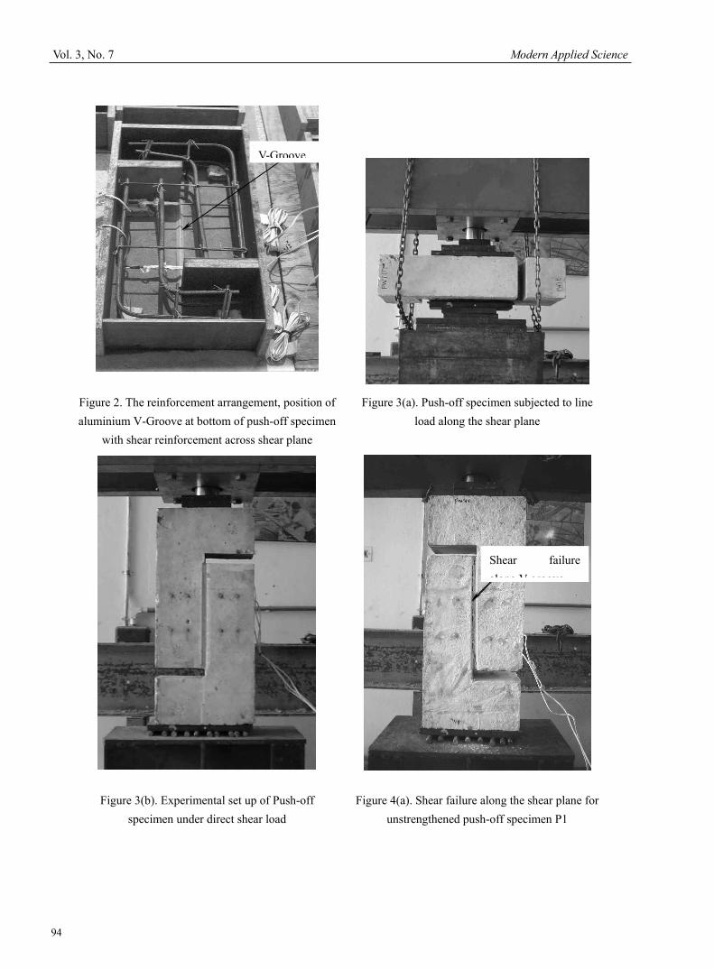
carried out further investigation on the shear strength of reinforced concrete push-off specimens both with and without existing crack along the shear plane. They investigated variables include concrete strength, arrangement of reinforcement, and shear transfer strength of dowel action of the reinforcing bar across the shear plane. It was found that the increase of reinforcement significantly increased the shear strength. Similar tests were conducted with embedded reinforcing bar to study the strength and deformation behaviour of normal and light weight concrete (Reinhardt and Walraven, 1982). The variables studied were the quality of concrete, reinforcement ratio, bar diameter, initial crack width and influence of repeated loading. The review showed that extensive research has been carried out to study the shear transfer capacity of reinforced concrete push-off specimens. However, strengthening push-off specimens has received very little attention among the researchers. Therefore, this study is required to evaluate the shear transfer capacity of the CFRP strengthened reinforced concrete precracked push-off specimens across the cracked shear plane with reference to the unstrengthened push-off specimens. The overall goal of this study was to investigate the shear transfer capacity and modes of failure of reinforced concrete precracked push-off specimens bonded externally with bi-directional CFRP sheets. The tests were performed with pre-existing crack along the shear plane of the push-off specimens prior to the application of direct shear load. This test was principally conducted to investigate the modes of failure such as debonding or peeling of CFRP sheets and rupture or fracture of CFRP sheet along the precracked shear plane of the strengthened push-off specimens. Specimens were reinforced by varying the amount of internal shear reinforcement across the shear plane. The influence of several features of the specimens including the pre-existing crack, amount of internal shear reinforcement and contribution of external CFRP reinforcement was studied. 2. Experimental Program 2.1 Fabrication and Description of Push-off Specimens The cross section of the push-off specimen is shown in Figure 1. For casting push-off specimens, the reinforcement mesh has been placed properly inside the wooden frame. Figure 2 shows the reinforcement arrangement of push-off specimen with shear reinforcement across the shear plane in the wooden formwork. Two aluminium angle sections of length 340 mm were used to develop V-grooves along the shear plane of the push-off specimens (i.e. both the front and rear faces). The first angle section was placed firmly at the bottom of the wooden mould in inverted V shape (see Figure 2). After the compaction of poured concrete mix, the second aluminium angle cross-section was placed at the top of wet concrete to make V-shaped groove along the shear plane and the surface was levelled using trowel without disturbing the angle section. The poker vibrator was used to compact the concrete mix. The concrete mix of grade 30 MPa was used to fabricate the specimens. Bi-directional Carbon Fibre Reinforced Polymer fabrics (Sika Wrap–160C 0/90) were used as external shear strengthening reinforcement. Table 1 shows properties of carbon fibre fabrics and epoxy resin (Sikadur330). 2.2 Description of Push-off Specimens The push-off specimens were grouped into two series labelled as P and PF. Each series had three specimens. Both the series P and PF were reinforced with same amount of internal shear reinforcement across the shear plane. The series P was subdivided into three specimens designated as P1 (ρ=0.14%), P2 (ρ=0.28%) and P3 (ρ=0.42%). The internal reinforcement in series PF was same as series P. However, these specimens were precracked and strengthened externally with CFRP fabric system represented as PF1, PF2, and PF3. The internal reinforcement details of the push-off specimens P1 & PF1, P2 & PF2, and P3 & PF3 are shown in the Figure 1(a), 1(b), and 1(c) respectively. 2.3 Instrumentation In P and PF series, the electrical strain gauges of gauge length 10 mm were affixed on the internal steel stirrups perpendicular to the shear plane to measure the strain in the closed steel stirrups. Two, three and four numbers of strain gauges were used in specimens P1 & PF1, P2 & PF2 and P3 & PF3 respectively. The difference between P and PF series was that the PF Series specimens had external strengthening system using CFRP sheets on the front and rear sides. The demec studs were placed on either side of the shear plane to measure the shear slip at each increment of load. The placement of demec studs remained same for all specimens in P and PF series. The positions of strain gauges and demec studs locations are depicted in Figures 1(a), 1(b) and 1(c). 2.4 Test Set-up and Procedure of Push-off Specimen All specimens in series P were deliberately cracked along the shear plane before testing. The specimen was placed horizontally as seen in Figure 3(a). A mild steel bar was provided along the top and bottom surface of grooves. The specimen was carefully placed under hydraulic jack to apply the line load along the V-Groove. The load was increased until a crack formed in the shear plane. Subsequently, the cracked specimen was inverted in vertical direction for the application of direct shear test. The direct shear test was performed in the same testing frame. Specimens were
Vol. 3, No. 7 Modern Applied Science
88
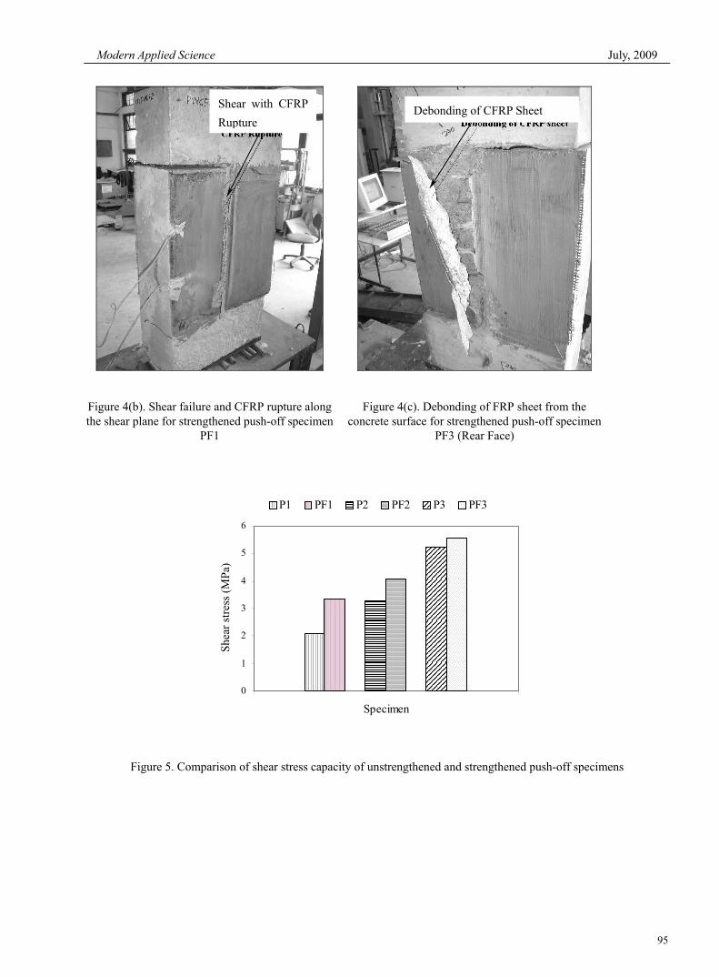
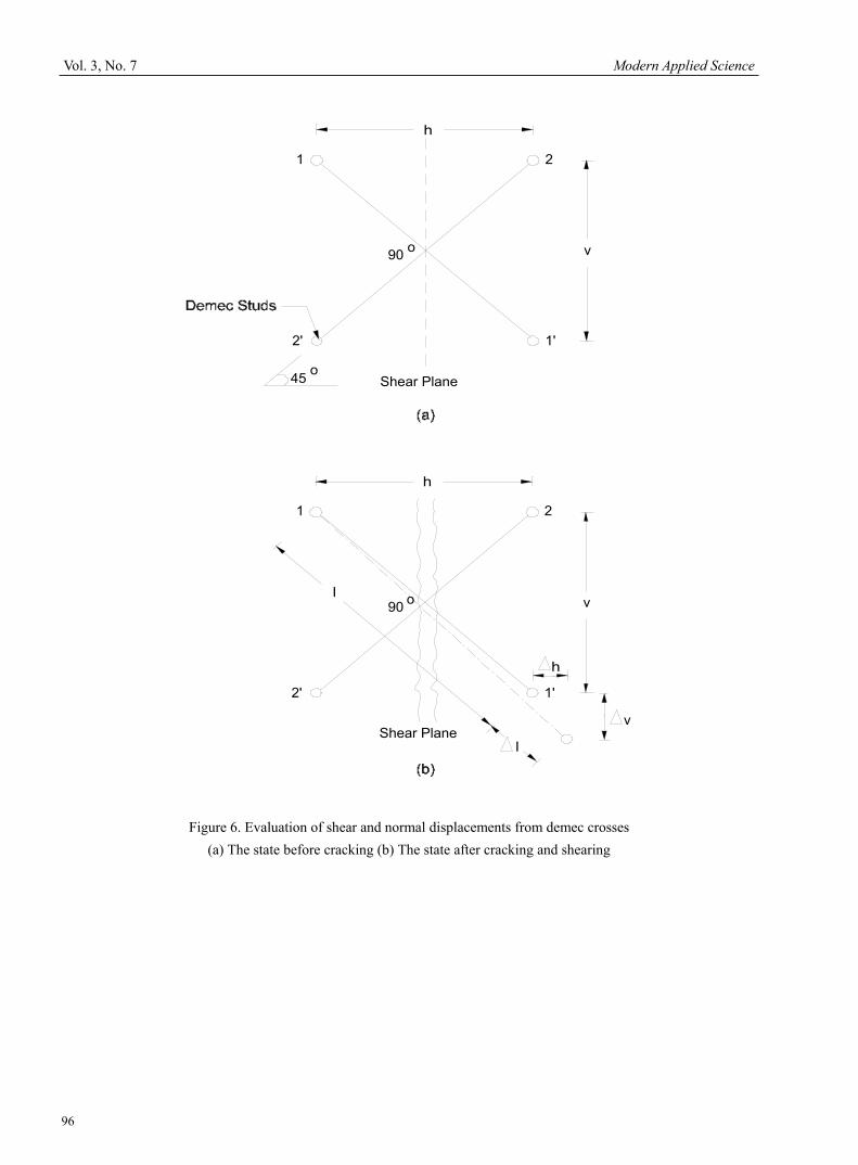
supported on roller to allow the top and bottom half of the specimen to move freely in horizontal direction during vertical loading. The specimen was loaded concentrically as indicated in Figure 3(b). The load was increased until failure occurred. After each increase of load, the slip along the shear plane was measured through the demec points. The strain gauges were connected to the data logger to measure the strain along the steel bars. At each increment of load, the strain readings were measured through the computerized data acquisition system until failure. In PF series, all specimens were strengthened using bi-directional CFRP sheets on the front and rear faces after precracking the specimen along the shear plane by the application of horizontal line load. These specimens were reinforced with similar amount and orientation (i.e. 0/90 degree) of external CFRP reinforcement. Table 2 summarises the amount of shear reinforcement, number of plies and orientation of CFRP sheets. The shear slips using the demec studs and strain in steel stirrups were measured using electrical strain gauges at each increment of load. From these measurements, the shear stress, shear displacement, normal displacement, and strain in internal crossings or steel stirrups were deduced. 3. Results and Discussion 3.1 Ultimate Failure Load and Failure Pattern Specimens P1 and PF1 had similar amount of internal shear reinforcement ratio of ρ=0.14%, and their area of shear plane was 120 mm x 340 mm. The ultimate failure load of the unstrengthened push-off specimen P1 was 85.50 kN and its corresponding shear stress was 2.09 MPa. The shear failure had occurred along the V-grooves or shear plane (see Figure 4(a)). These grooves were provided on both faces of the push-off specimens to achieve the shear failure along the groove or shear plane. However, in the case of specimen PF1, the external CFRP sheets were applied on the front and rear faces. This specimen was failed due to rupture or fracture of CFRP sheets along the shear plane at a maximum load of 131.82 kN (see Figure 4(b)). At ultimate, the attained shear stress of the strengthened specimen was 3.23 MPa. The shear stress enhancement was 55% higher than the unstrengthened specimen P1. It was attributed to the presence of external CFRP reinforcement. In specimens P2 and PF2, the amount of internal shear reinforcement ratio was twice that of specimens P1 or PF1. The unstrengthened specimen P2 had attained a maximum load of 135.38 kN with a corresponding shear stress of 3.30 MPa. Spalling of concrete was observed at bottom of the shear plane before it reached the failure load. In specimen PF2, an attempt was made to enhance the ultimate load capacity by applying one layer of CFRP sheet on the sides similar to the strengthened specimen PF1. The strengthened specimen PF2 was failed with a CFRP fracture mode of failure along the shear plane at an ultimate load of 167.45 kN (corresponding to a shear stress of 4.10 MPa) similar to the specimen PF1. The shear stress enhancement was increased 24% over the specimen P2. It was also observed that a yielding of reinforcement in the steel stirrups at peak load before the failure of external CFRP reinforcement. The internal shear reinforcement of specimens P3 and PF3 were three times that of the specimen P1, whereas the external reinforcement of the specimen PF3 was similar to specimens PF1 and PF2. The specimen P3 failed at a peak load of 213.87 kN with a shear stress of 5.24 MPa. The ultimate failure load was found to be increased with increase in amount of internal shear reinforcement. All the unstrengthened specimens P1, P2 and P3 failed along the shear plane or the V-grooves on the front and rear sides. The externally strengthened specimen PF3 was failed at the ultimate load of 228.02 kN with a corresponding shear stress of 5.58 MPa. There was an enhancement of 7% over the unstrengthened push-off specimen P3. At ultimate failure, the specimen PF3 had yielding of internal steel stirrups similar to specimen PF2 but failed in debonding of CFRP sheets on the rear face. Figure 4(c) shows the debonding failure pattern of the strengthened push-off specimen PF3. From the investigation, it was found that the increased amount of internal shear reinforcement in the strengthened push-off specimens reduced the contribution of shear enhancement by the external CFRP reinforcement. Table 3 illustrates the summary of experimental investigation of the unstrengthened and strengthened push-off specimens. Figure 5 shows the comparison of strengthened and unstrengthened push-off specimens. 3.2 Instrumentation of Demec Points The procedure of measuring the crack width and its subsequent development, together with the shear displacement was common to all specimens. The demec crosses were located at 45 degree to the horizontal along the shear plane. A set of measurements was recorded at each increment of load. From the Figures 6(a) and 6(b), the shear and normal displacement can be deduced by the simple calculation as below:
From Line 1-1′ of Figure 6(a)
2 2l h v= + (1)
and from Figure 6(b)
Modern Applied Science July, 2009
89
( ) ( )2 2l l h h v v+Δ = ++Δ +Δ (2)
Squaring both sides of these two equations and subtracting Eqn. 1 from 2 will yield to the following (Neglecting small terms to higher orders):
2 . 2 . 2 .l l h h v vΔ = Δ + Δ (3)
By applying a similar procedure to line 2-2′ the following equation can easily be obtained:
2 '. ' 2 . 2 .l l h h v vΔ = Δ − Δ (4)
Considering l=l’ and subtracting Eqn. 4 from 3 will yield to
( )'2lv l lν
Δ = Δ −Δ (5)
Adding Eqn. 3 and 4 will give
( )'2lh l lh
Δ = Δ + Δ (6)
In all specimens l=l’=150mm and the angle of inclination to the horizontal of each of these two lines was 45 degree, therefore;
v=h=150/√2 (7)
Shear displacement
( )1 '2
v l lΔ = Δ −Δ (8)
Normal displacement
( )1 '2
h l lΔ = Δ + Δ (9)
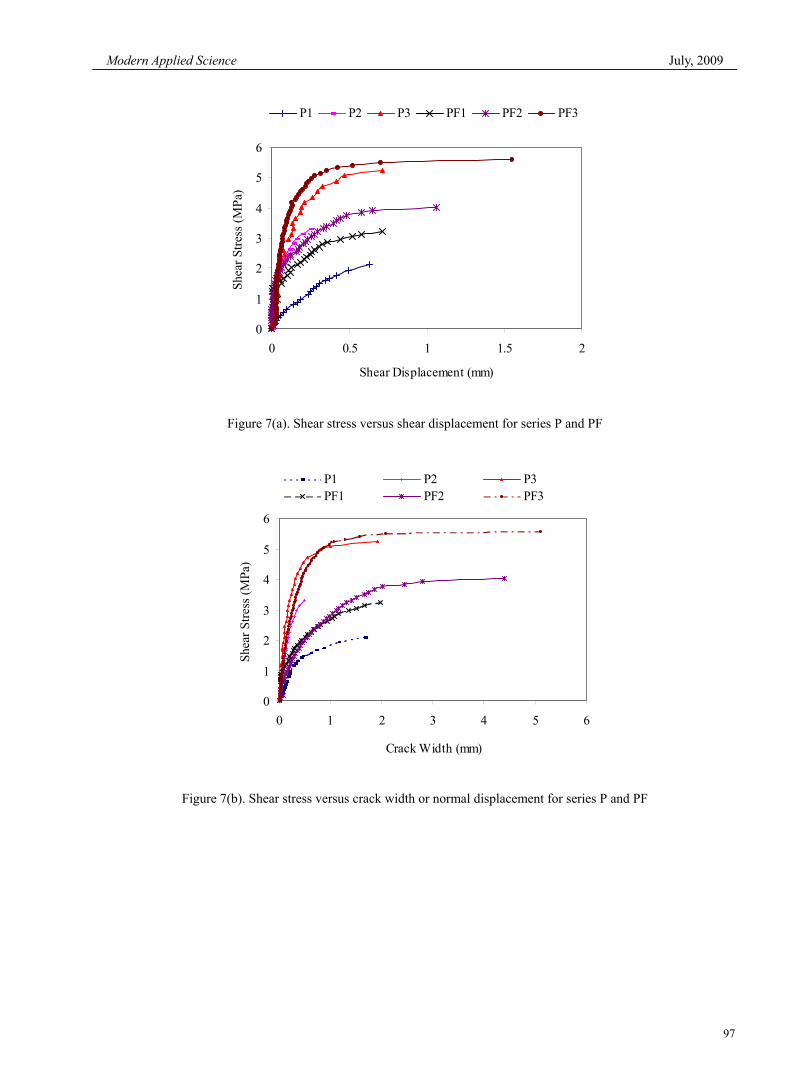
Where Δl and Δl′ are the changes in length of lines 1-1′ and 2-2′ respectively, as measured by the demec gauge between each pair of demec studs or points. Throughout the investigation, Eqns. 8 and 9 have been used to evaluate the shear and normal displacement across the crack. 3.3 Shear Stress-Shear displacement and Crack width Relationship Figure 7(a) depicts the shear stress versus shear displacement of the strengthened and unstrengthened push-off specimens. The test results indicate that the strengthened push-off specimens have measured significantly lesser shear displacement at each increment of load than the unstrengthened push-off specimens. But there was a sudden increase in shear slip at the peak load in the strengthened push-off specimens due to the fact that the FRP composites do not have any yielding plateau. The failure of the strengthened push-off specimens occurred with a loud noise. It can also be observed from the Figure 7(a), the stiffness of the strengthened push-off specimens was greater than the unstrengthened one. The direct shear test of the unstrengthened push-off specimens shows that shear stress increases with increase of internal shear reinforcement ratio. However in externally bonded push-off specimens, the contribution of CFRP sheet decreases with an increase in the amount of internal shear reinforcement ratio. The shear stress versus crack width of the strengthened and unstrengthened push-off specimens is shown in Figure 7(b). One can see from the Figure 7(b), the crack width or normal displacement of the strengthened push-off specimens was relatively less in comparison to the unstrengthened push-off specimens except specimen PF2. In specimen P2, the observed crack width was less than the strengthened specimen PF2. This might be due to the existence of smaller initial crack width along the shear plane. It was observed that the reinforced concrete specimens with large initial crack width were lower in stiffness than specimens with smaller initial crack width. Increased shear stress increases the shear displacement and crack width in the unstrengthened push-off specimens but in strengthened push-off specimens the increase of displacement level was relatively very less in comparison to the unstrengthened push-off specimens for the same load. It shows that the external bonded CFRP sheets control the slip along the shear plane and it also precludes the
Vol. 3, No. 7 Modern Applied Science
90
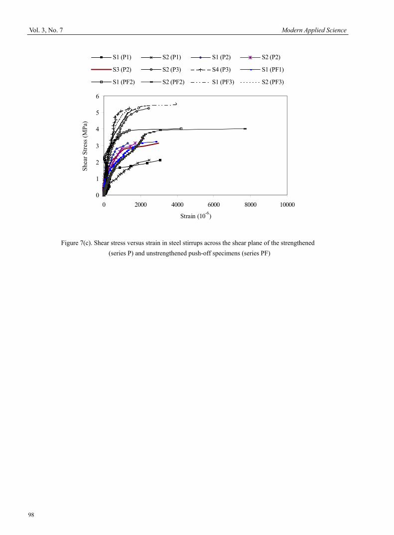
widening of crack. It was also noticed that the strengthened push-off specimens showed greater value of shear displacement and crack width at failure load than unstrengthened push-off specimens. 3.4 Shear Stress –Stirrups Strain Profile As illustrated in Figure 7(c), the shear stress versus steel strain curve of strengthened and unstrengthened push-off specimens exhibits a similar behaviour. It was observed that the steel strains in the CFRP strengthened push-off specimens have attained lesser strain value than the unstrengthened push-off specimens for the same load. This was attributed to the presence of external CFRP reinforcement. But the strengthened specimens have attained a maximum strain in steel stirrups at the ultimate failure load. Increased applied load increases the strain values in strengthened specimens. In the strengthened push-off specimens, the cracked surfaces had a sign of separation, followed by the combination of yielding of steel and rupture of CFRP sheet along the shear plane or debonding of concrete layer. This external CFRP reinforcement had probably controlled the shear slip as well as widening of the cracks. During the application of direct shear load, specimens PF1 and PF2 had failed in shear-CFRP rupture along the shear plane, however, specimen PF3 was failed in debonding of concrete surface. 3.5 Experimental Observations The key observation are stated below:
• The shear stress capacity of the strengthened push-off specimens was increased in the range of 7% to 56% higher than the unstrengthened push-off specimens.
• Test results indicate that shear stress of the unstrengthened specimens increases with increase of internal shear reinforcement ratio. However, in externally bonded push-off specimens, the contribution of CFRP sheet decreases with an increase in the amount of internal shear reinforcement ratio (see Table 3).
• The shear displacement and normal displacement or crack width of the strengthened specimens was less compared to the unstrengthened specimens for the same load. It shows that the external bonded CFRP sheets control the slip along the shear plane and it also precludes the widening of crack. However, the strengthened specimens had attained greater shear and normal displacement over the unstrengthened push-off specimens at the ultimate failure load.
• The stiffness of the strengthened specimens was greater than the unstrengthened push-off specimens. • The shear stress-strain behaviour of the strengthened push-off specimens is similar to that of the
unstrengthened specimens. Similar to the shear and normal displacements, the steel strain in the strengthened specimens was smaller than the unstrengthened push-off specimens for the same load.
5. Conclusions The shear stress enhancement of the strengthened push-off specimens varies in the range of 7% to 56% over the unstrengthened push-off specimens. The contribution of the CFRP diminishes with increased amount of internal shear reinforcement ratio. The external CFRP reinforcement had controlled the shear slip along the shear plane and crack width. In the unstrengthened push-off specimens, the pre-existing crack along the shear plane will reduce the ultimate shear transfer capacity and increase of shear slip at all load levels (Hofbeck et al., 1969). However in strengthened specimens, the external CFRP reinforcement will control the increase of slip and increase the ultimate shear stress transfer capacity along the shear plane. The shear displacement and normal displacement or crack width of the strengthened specimens was less compared to the unstrengthened specimens for the same load, however, the strengthened specimens had attained greater shear and normal displacement over the unstrengthened push-off specimens at the ultimate failure load. There was a sudden increase of shear displacement and crack width at the peak load. The stiffness of the strengthened specimens was greater than the unstrengthened push-off specimens. Similarly, in the strengthened push-off specimens, the strain in steel stirrups was smaller than the unstrengthened push-off specimens for the same load. The shear stress-strain behaviour of the strengthened push-off specimens is similar to that of the unstrengthened specimens. References Adhikary, B. B., and Mutsuyoshi, H. (2004). Behaviour of concrete beams strengthened in shear with carbon fibre sheets. Journal of composites for construction, 8(3), 258-264. Alex, Li., Assih J., and Delmas, Y. (2001). Shear strengthening of RC beams with externally bonded CFRP sheets. Journal of Structural Engineering, 127(4), 374-380. Al-Mahaidi, R., Taplin, G., and Susa, J. (2000). Strengthening of shear damaged reinforced concrete T-beam bridges with CFRP strips. Birkeland, P. W., and Brikeland, H. W. (1966). Connections in precast concrete constructions. ACI Journal, 63(3), 345-368.
Modern Applied Science July, 2009
91
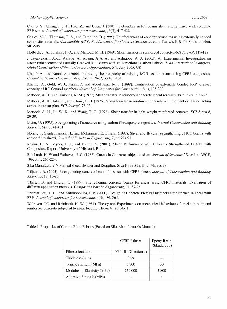
Cao, S. Y., Cheng, J. J. F., Hao, Z., and Chen, J. (2005). Debonding in RC beams shear strengthened with complete FRP wraps. Journal of composites for construction, , 9(5), 417-428. Chajes, M. J., Thomson, T. A., and Tarantino, B. (1995). Reinforcement of concrete structures using externally bonded composite materials. Non-metallic (FRP) Reinforcement for Concrete Structures, ed. L Taerwe, E & FN Spon, London, 501-508. Hofbeck, J. A., Ibrahim, I. O., and Mattock, M. H. (1969). Shear transfer in reinforced concrete. ACI Journal, 119-128. J. Jayaprakash, Abdul Aziz A. A., Abang, A A. A., and Ashrabov, A. A. (2005). An Experimental Investigation on Shear Enhancement of Partially Cracked RC Beams with Bi Directional Carbon Fabrics. Sixth International Congress, Global Construction-Ultimate Concrete Opportunities, 5-7, July 2005, UK. Khalifa A., and Nanni, A. (2000). Improving shear capacity of existing RC T-section beams using CFRP composites. Cement and Concrete Composites, Vol. 22, No.2, pp 165-174. Khalifa, A., Gold, W. J., Nanni, A and Abdel Aziz, M. I. (1998). Contribution of externally bonded FRP to shear capacity of RC flexural members. Journal of Composites for Construction, 2(4), 195-202. Mattock, A. H., and Hawkins, N. M. (1972). Shear transfer in reinforced concrete recent research, PCI Journal, 55-75. Mattock, A. H., Johal, L, and Chow, C. H. (1975). Shear transfer in reinforced concrete with moment or tension acting across the shear plan, PCI Journal, 76-93. Mattock, A. H., Li, W. K., and Wang, T. C. (1976). Shear transfer in light weight reinforced concrete. PCI Journal, 20-39. Meier, U. (1995). Strengthening of structures using carbon fibre/epoxy composites. Journal Construction and Building Material, 9(9), 341-451. Norris, T., Saadatmanesh, H., and Mohammad R. Ehsani. (1997). Shear and flexural strengthening of R/C beams with carbon fibre sheets, Journal of Structural Engineering, 7, pp.903-911. Raghu, H. A., Myers, J. J., and Nanni, A. (2001). Shear Performance of RC beams Strengthened In Situ with Composites. Report, University of Missouri, Rolla. Reinhardt. H. W and Walraven. J. C. (1982). Cracks in Concrete subject to shear, Journal of Structural Division, ASCE, 106, ST1, 207-224. Sika Manufacturer’s Manual sheet, Switzerland (Supplier: Sika Kima Sdn. Bhd, Malaysia) Täljsten., B. (2003). Strengthening concrete beams for shear with CFRP sheets, Journal of Construction and Building Materials, 17, 15-26. Täljsten B, and Elfgren. L (1999). Strengthening concrete beams for shear using CFRP materials: Evaluation of different application methods. Composites Part B: Engineering, 31, 87-96. Triantafillou, T. C., and Antonopoulos, C P. (2000). Design of Concrete Flexural members strengthened in shear with FRP. Journal of composites for construction, 4(4), 198-205. Walraven, J.C. and Reinhardt, H. W. (1981). Theory and Experiments on mechanical behaviour of cracks in plain and reinforced concrete subjected to shear loading, Heron V. 26, No. 1. Table 1. Properties of Carbon Fibre Fabrics (Based on Sika Manufacture’s Manual)
CFRP Fabrics Epoxy Resin (Sikadur330)
Fibre orientation 0/90 (Bi-Directional) ---
Thickness (mm) 0.09 ---
Tensile strength (MPa) 3,800 30
Modulus of Elasticity (MPa) 230,000 3,800
Adhesive Strength (MPa) --- 4
Vol. 3, No. 7 Modern Applied Science
92
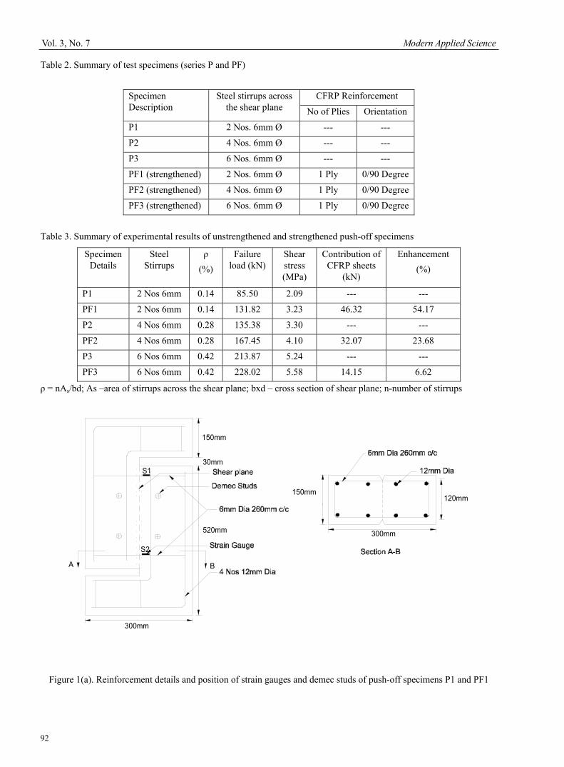
Table 2. Summary of test specimens (series P and PF)
Specimen Description
Steel stirrups across the shear plane
CFRP Reinforcement
No of Plies Orientation
P1 2 Nos. 6mm Ø --- ---
P2 4 Nos. 6mm Ø --- ---
P3 6 Nos. 6mm Ø --- ---
PF1 (strengthened) 2 Nos. 6mm Ø 1 Ply 0/90 Degree
PF2 (strengthened) 4 Nos. 6mm Ø 1 Ply 0/90 Degree
PF3 (strengthened) 6 Nos. 6mm Ø 1 Ply 0/90 Degree
Table 3. Summary of experimental results of unstrengthened and strengthened push-off specimens ρ = nAs/bd; As –area of stirrups across the shear plane; bxd – cross section of shear plane; n-number of stirrups
150mm
520mm
30mm
300mm
S1
S2
120mm
300mm
150mm
A B
Figure 1(a). Reinforcement details and position of strain gauges and demec studs of push-off specimens P1 and PF1
Specimen Details
Steel Stirrups
ρ (%)
Failure load (kN)
Shear stress (MPa)
Contribution of CFRP sheets
(kN)
Enhancement (%)
P1 2 Nos 6mm 0.14 85.50 2.09 --- ---
PF1 2 Nos 6mm 0.14 131.82 3.23 46.32 54.17
P2 4 Nos 6mm 0.28 135.38 3.30 --- ---
PF2 4 Nos 6mm 0.28 167.45 4.10 32.07 23.68
P3 6 Nos 6mm 0.42 213.87 5.24 --- ---
PF3 6 Nos 6mm 0.42 228.02 5.58 14.15 6.62
Modern Applied Science July, 2009
93
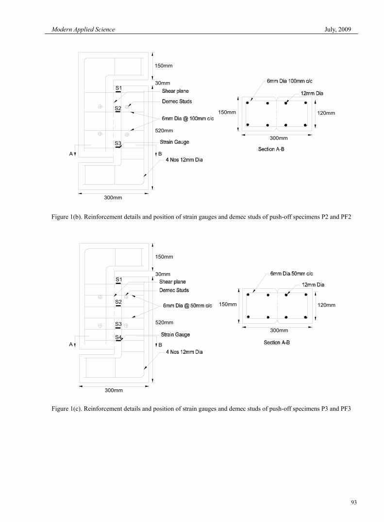
150mm
520mm
30mm
300mm
S2
S1
S3
120mm
300mm
150mm
BA
Figure 1(b). Reinforcement details and position of strain gauges and demec studs of push-off specimens P2 and PF2
150mm
520mm
30mm
300mm
S1
S2
S3
S4
120mm
300mm
150mm
BA
Figure 1(c). Reinforcement details and position of strain gauges and demec studs of push-off specimens P3 and PF3
Vol. 3, No. 7 Modern Applied Science
94
Figure 2. The reinforcement arrangement, position of aluminium V-Groove at bottom of push-off specimen
with shear reinforcement across shear plane
Figure 3(a). Push-off specimen subjected to line load along the shear plane
Figure 3(b). Experimental set up of Push-off specimen under direct shear load
Figure 4(a). Shear failure along the shear plane for unstrengthened push-off specimen P1
V-Groove
Shear failure along V groove
Modern Applied Science July, 2009
95
0
1
2
3
4
5
6
Specimen
Shea
r stre
ss (M
Pa)
P1 PF1 P2 PF2 P3 PF3
Figure 5. Comparison of shear stress capacity of unstrengthened and strengthened push-off specimens
Figure 4(b). Shear failure and CFRP rupture along the shear plane for strengthened push-off specimen
PF1
Figure 4(c). Debonding of FRP sheet from the
concrete surface for strengthened push-off specimen PF3 (Rear Face)
Shear with CFRP Rupture
Debonding of CFRP Sheet
Vol. 3, No. 7 Modern Applied Science
96
90 o
45 oShear Plane
h
v
1
1'
2
2'
90 o
Shear Plane
h
v
1
1'
2
2'
l
l
v
h
Figure 6. Evaluation of shear and normal displacements from demec crosses (a) The state before cracking (b) The state after cracking and shearing
Modern Applied Science July, 2009
97
0
1
2
3
4
5
6
0 0.5 1 1.5 2
Shear Displacement (mm)
Shea
r Stre
ss (M
Pa)
P1 P2 P3 PF1 PF2 PF3
Figure 7(a). Shear stress versus shear displacement for series P and PF
0
1
2
3
4
5
6
0 1 2 3 4 5 6
Crack Width (mm)
Shea
r Stre
ss (M
Pa)
P1 P2 P3PF1 PF2 PF3
Figure 7(b). Shear stress versus crack width or normal displacement for series P and PF
Vol. 3, No. 7 Modern Applied Science
98
0
1
2
3
4
5
6
0 2000 4000 6000 8000 10000
Strain (10-6)
Shea
r Stre
ss (M
Pa)
S1 (P1) S2 (P1) S1 (P2) S2 (P2)
S3 (P2) S2 (P3) S4 (P3) S1 (PF1)
S1 (PF2) S2 (PF2) S1 (PF3) S2 (PF3)
Figure 7(c). Shear stress versus strain in steel stirrups across the shear plane of the strengthened (series P) and unstrengthened push-off specimens (series PF)