unistrut concrete inserts
DESCRIPTION
Concrete Inserts in Bridges / building for installation of MEP cables or PHE items.TRANSCRIPT

Maximum Support for Your Projects
Broadest Range of Concrete Solutions
With the widest range of styles and accessories in the
industry, Unistrut concrete inserts give you more ways
to design and build your structures. They are available
in a wide range of finishes and materials, including
stainless steel and both polyester and vinyl ester fiber-
glass, offering advantages for every application… even
highly corrosive environments.
From office buildings and airport terminals to plants,
hotels and service tunnels, Unistrut offers concrete
inserts to solve all your insert application requirements.
Delivery from Local Inventories
Unistrut Service Centers stock most standard Unistrut
components and are located in principal cities through-
out the United States and Canada to serve you quickly
and directly.
Technical Service
Unistrut Service Centers are equipped to provide a
range of technical support for any concrete anchoring
project. These and other
important value-added
services are part of
every concrete insert
we manufacture.
Custom Fabrication
The inherent versatility of Unistrut concrete inserts seldom requires
special sections or fittings. To satisfy special requirements, however,
Service Centers can custom fabricate special inserts, connectors or
accessories to your specifications.
“J” hangers can be attached directly to the concrete insert to support pipe or conduit.
Metal framing combined with insertsprovides support service tunnels.
The heavy duty inserts are usedto support the facia.
Concrete inserts are an ideal solutionfor drop rod support of trapeze.
UNISTRUTConcrete Inserts2
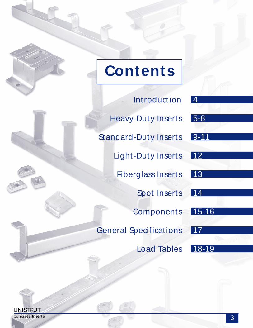
Contents
Introduction
Heavy-Duty Inserts
Standard-Duty Inserts
Light-Duty Inserts
Fiberglass Inserts
Spot Inserts
Components
General Specifications
Load Tables
4
5-8
9-11
12
13
14
15-16
17
18-19
UNISTRUTConcrete Inserts 3
UNISTRUTConcrete Inserts4
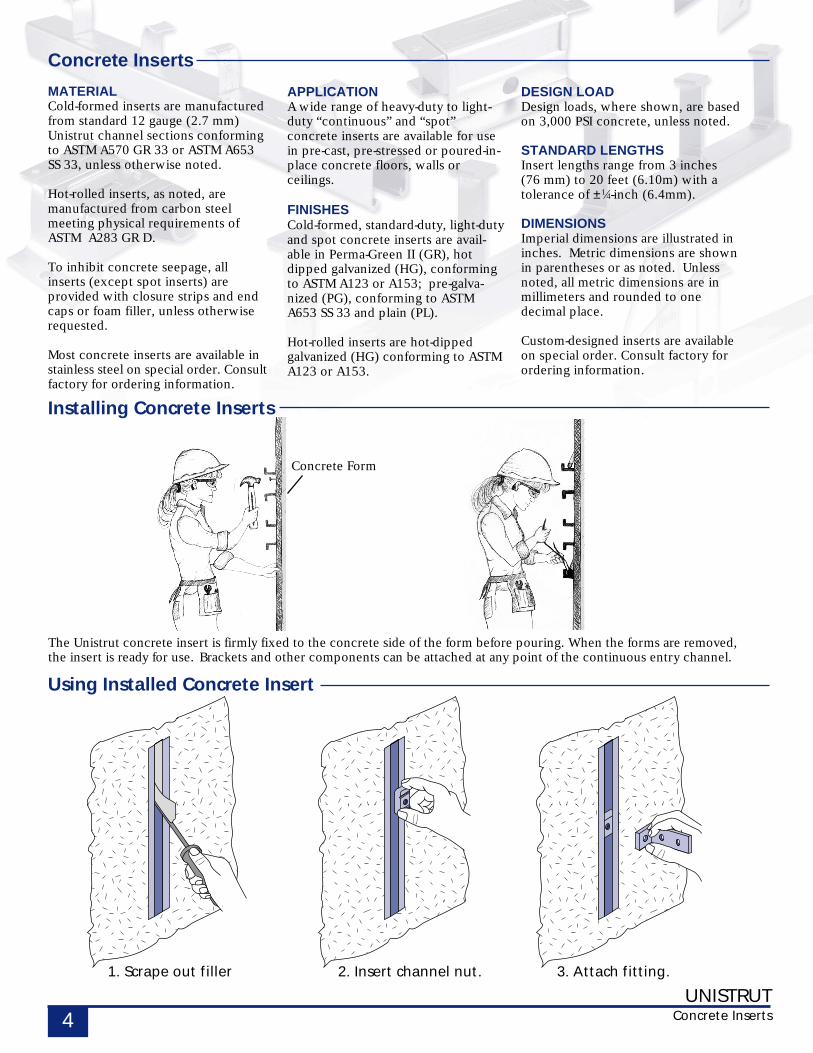
The Unistrut concrete insert is firmly fixed to the concrete side of the form before pouring. When the forms are removed,the insert is ready for use. Brackets and other components can be attached at any point of the continuous entry channel.
1. Scrape out filler 2. Insert channel nut. 3. Attach fitting.
Using Installed Concrete Insert
Installing Concrete Inserts
Concrete Inserts
MATERIALCold-formed inserts are manufacturedfrom standard 12 gauge (2.7 mm)Unistrut channel sections conformingto ASTM A570 GR 33 or ASTM A653SS 33, unless otherwise noted.
Hot-rolled inserts, as noted, aremanufactured from carbon steelmeeting physical requirements ofASTM A283 GR D.
To inhibit concrete seepage, allinserts (except spot inserts) areprovided with closure strips and endcaps or foam filler, unless otherwiserequested.
Most concrete inserts are available instainless steel on special order. Consultfactory for ordering information.
DESIGN LOADDesign loads, where shown, are basedon 3,000 PSI concrete, unless noted.
STANDARD LENGTHSInsert lengths range from 3 inches(76 mm) to 20 feet (6.10m) with atolerance of ±1⁄4-inch (6.4mm).
DIMENSIONSImperial dimensions are illustrated ininches. Metric dimensions are shownin parentheses or as noted. Unlessnoted, all metric dimensions are inmillimeters and rounded to onedecimal place.
Custom-designed inserts are availableon special order. Consult factory forordering information.
APPLICATIONA wide range of heavy-duty to light-duty “continuous” and “spot”concrete inserts are available for usein pre-cast, pre-stressed or poured-in-place concrete floors, walls orceilings.
FINISHESCold-formed, standard-duty, light-dutyand spot concrete inserts are avail-able in Perma-Green II (GR), hotdipped galvanized (HG), conformingto ASTM A123 or A153; pre-galva-nized (PG), conforming to ASTMA653 SS 33 and plain (PL).
Hot-rolled inserts are hot-dippedgalvanized (HG) conforming to ASTMA123 or A153.
Concrete Form
UNISTRUTConcrete Inserts 5
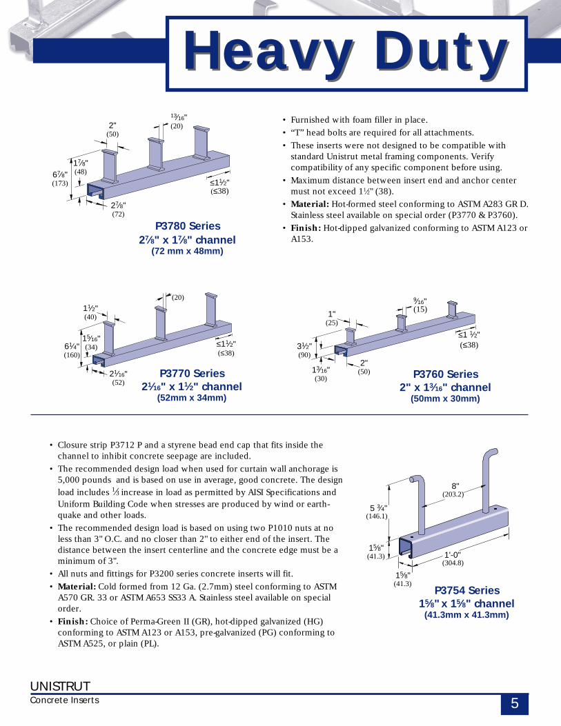
Heavy DutyHeavy Duty• Furnished with foam filler in place.
• “T” head bolts are required for all attachments.
• These inserts were not designed to be compatible withstandard Unistrut metal framing components. Verifycompatibility of any specific component before using.
• Maximum distance between insert end and anchor centermust not exceed 11⁄2" (38).
• Material: Hot-formed steel conforming to ASTM A283 GR D.Stainless steel available on special order (P3770 & P3760).
• Finish: Hot-dipped galvanized conforming to ASTM A123 orA153.
≤11⁄2"(≤38)
17⁄8"(48)67⁄8"
(173)
27⁄8"(72)
13⁄16"(20)2"
(50)
P3780 Series27⁄8" x 17⁄8" channel
(72 mm x 48mm)
• Closure strip P3712 P and a styrene bead end cap that fits inside thechannel to inhibit concrete seepage are included.
• The recommended design load when used for curtain wall anchorage is5,000 pounds and is based on use in average, good concrete. The design
load includes 1⁄3 increase in load as permitted by AISI Specifications andUniform Building Code when stresses are produced by wind or earth-quake and other loads.
• The recommended design load is based on using two P1010 nuts at noless than 3" O.C. and no closer than 2" to either end of the insert. Thedistance between the insert centerline and the concrete edge must be aminimum of 3".
• All nuts and fittings for P3200 series concrete inserts will fit.
• Material: Cold formed from 12 Ga. (2.7mm) steel conforming to ASTMA570 GR. 33 or ASTM A653 SS33 A. Stainless steel available on specialorder.
• Finish: Choice of Perma-Green II (GR), hot-dipped galvanized (HG)conforming to ASTM A123 or A153, pre-galvanized (PG) conforming toASTM A525, or plain (PL).
(203.2)8"
1'-0"(304.8)
15⁄8"(41.3)
15⁄8"(41.3)
5 3⁄4"(146.1)
P3754 Series15⁄8" x 15⁄8" channel
(41.3mm x 41.3mm)
(15)9⁄16"
≤1 1⁄2"(≤38)31⁄2"
(90)
13⁄16"(30)
2"(50)
1"(25)
P3760 Series2" x 13⁄16" channel
(50mm x 30mm)
≤11⁄2"(≤38)
(20)
15⁄16"(34)61⁄4"
(160)
21⁄16"(52)
11⁄2"(40)
P3770 Series21⁄16" x 11⁄2" channel
(52mm x 34mm)
UNISTRUTConcrete Inserts6
3"(76.2)
3"(76.2)
Load
15⁄8"(41.3)5 3⁄4"
(146.1)
7⁄8"(22)
0.11"(3)
5⁄16"(8)
1"
2"(50)
13⁄16"(30)
31⁄2"
(90)
Heavy Duty
15⁄16"(33)
0.20"(5)
5⁄8"(15)
0.16 (4)
17⁄8"
(48)6
7⁄8"(173)
2 7⁄8"(72)
7⁄8"(22)
0.16"(4)
7⁄16"(11)
0.14 (3.5)
15⁄16"(34)
61⁄4"
(160)
21⁄16"(52)
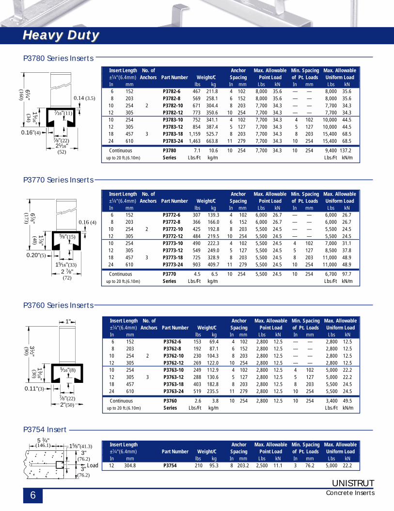
Insert Length No. of Anchor Max. Allowable Min. Spacing Max. Allowable±1⁄4" (6.4mm) Anchors Part Number Weight/C Spacing Point Load of Pt. Loads Uniform LoadIn mm lbs kg In mm Lbs kN In mm Lbs kN6 152 P3772-6 307 139.3 4 102 6,000 26.7 — — 6,000 26.78 203 P3772-8 366 166.0 6 152 6,000 26.7 — — 6,000 26.7
10 254 2 P3772-10 425 192.8 8 203 5,500 24.5 — — 5,500 24.512 305 P3772-12 484 219.5 10 254 5,500 24.5 — — 5,500 24.510 254 P3773-10 490 222.3 4 102 5,500 24.5 4 102 7,000 31.112 305 P3773-12 549 249.0 5 127 5,500 24.5 5 127 8,500 37.818 457 3 P3773-18 725 328.9 8 203 5,500 24.5 8 203 11,000 48.924 610 P3773-24 903 409.7 11 279 5,500 24.5 10 254 11,000 48.9
Continuous P3770 4.5 6.5 10 254 5,500 24.5 10 254 6,700 97.7up to 20 ft.(6.10m) Series Lbs/Ft kg/m Lbs/Ft kN/m
P3770 Series Inserts
Insert Length No. of Anchor Max. Allowable Min. Spacing Max. Allowable±1⁄4" (6.4mm) Anchors Part Number Weight/C Spacing Point Load of Pt. Loads Uniform LoadIn mm lbs kg In mm Lbs kN In mm Lbs kN6 152 P3762-6 153 69.4 4 102 2,800 12.5 — — 2,800 12.58 203 P3762-8 192 87.1 6 152 2,800 12.5 — — 2,800 12.5
10 254 2 P3762-10 230 104.3 8 203 2,800 12.5 — — 2,800 12.512 305 P3762-12 269 122.0 10 254 2,800 12.5 — — 2,800 12.510 254 P3763-10 249 112.9 4 102 2,800 12.5 4 102 5,000 22.212 305 3 P3763-12 288 130.6 5 127 2,800 12.5 5 127 5,000 22.218 457 P3763-18 403 182.8 8 203 2,800 12.5 8 203 5,500 24.524 610 P3763-24 519 235.5 11 279 2,800 12.5 10 254 5,500 24.5
Continuous P3760 2.6 3.8 10 254 2,800 12.5 10 254 3,400 49.5up to 20 ft.(6.10m) Series Lbs/Ft kg/m Lbs/Ft kN/m
P3760 Series Inserts
Insert Length Anchor Max. Allowable Min. Spacing Max. Allowable±1⁄4" (6.4mm) Part Number Weight/C Spacing Point Load of Pt. Loads Uniform LoadIn mm lbs kg In mm Lbs kN In mm Lbs kN12 304.8 P3754 210 95.3 8 203.2 2,500 11.1 3 76.2 5,000 22.2
P3754 Insert
Insert Length No. of Anchor Max. Allowable Min. Spacing Max. Allowable±1⁄4" (6.4mm) Anchors Part Number Weight/C Spacing Point Load of Pt. Loads Uniform LoadIn mm lbs kg In mm Lbs kN In mm Lbs kN6 152 P3782-6 467 211.8 4 102 8,000 35.6 — — 8,000 35.68 203 P3782-8 569 258.1 6 152 8,000 35.6 — — 8,000 35.6
10 254 2 P3782-10 671 304.4 8 203 7,700 34.3 — — 7,700 34.312 305 P3782-12 773 350.6 10 254 7,700 34.3 — — 7,700 34.310 254 P3783-10 752 341.1 4 102 7,700 34.3 4 102 10,000 44.512 305 P3783-12 854 387.4 5 127 7,700 34.3 5 127 10,000 44.518 457 3 P3783-18 1,159 525.7 8 203 7,700 34.3 8 203 15,400 68.524 610 P3783-24 1,463 663.8 11 279 7,700 34.3 10 254 15,400 68.5
Continuous P3780 7.1 10.6 10 254 7,700 34.3 10 254 9,400 137.2up to 20 ft.(6.10m) Series Lbs/Ft kg/m Lbs/Ft kN/m
P3780 Series Inserts
Heavy Duty
UNISTRUTConcrete Inserts 7
12" (305mm) Rebarto be fitted intosleeves before
placing into form
7" (178mm) MIN.
Edge
of P
anel
MIN. 7" x 3"(178mm x 76mm)
cut-out in meshInsulated Panel
3" (7
6mm
) MIN
.
2" (51mm) MIN.thickness
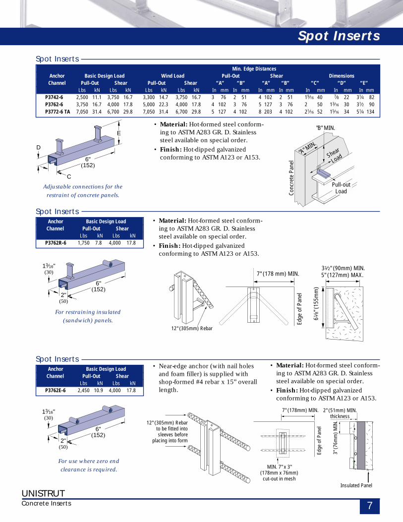
• Near-edge anchor (with nail holesand foam filler) is supplied withshop-formed #4 rebar x 15” overalllength.
6"(152)
13⁄16"(30)
2"(50)
6"(152)
13⁄16"(30)
2"(50)
6"(152)
C
E
D
Min. Edge DistancesAnchor Basic Design Load Wind Load Pull-Out Shear DimensionsChannel Pull-Out Shear Pull-Out Shear “A” “B” “A” “B” “C” “D” “E”
Lbs kN Lbs kN Lbs kN Lbs kN In mm In mm In mm In mm In mm In mm In mmP3742-6 2,500 11.1 3,750 16.7 3,300 14.7 3,750 16.7 3 76 2 51 4 102 2 51 19⁄16 40 7⁄8 22 31⁄4 82P3762-6 3,750 16.7 4,000 17.8 5,000 22.3 4,000 17.8 4 102 3 76 5 127 3 76 2 50 13⁄16 30 31⁄2 90P3772-6 TA 7,050 31.4 6,700 29.8 7,050 31.4 6,700 29.8 5 127 4 102 8 203 4 102 21⁄16 52 15⁄16 34 51⁄4 134
Spot Inserts
Anchor Basic Design Load Channel Pull-Out Shear
Lbs kN Lbs kNP3762R-6 1,750 7.8 4,000 17.8
Spot Inserts
• Material: Hot-formed steel conform-ing to ASTM A283 GR. D. Stainlesssteel available on special order.
• Finish: Hot-dipped galvanizedconforming to ASTM A123 or A153.
For use where zero end
clearance is required.
For restraining insulated
(sandwich) panels.
Adjustable connections for the
restraint of concrete panels.
Anchor Basic Design Load Channel Pull-Out Shear
Lbs kN Lbs kNP3762E-6 2,450 10.9 4,000 17.8
Spot Inserts
• Material: Hot-formed steel conform-ing to ASTM A283 GR. D. Stainlesssteel available on special order.
• Finish: Hot-dipped galvanizedconforming to ASTM A123 or A153.
• Material: Hot-formed steel conform-ing to ASTM A283 GR. D. Stainlesssteel available on special order.
• Finish: Hot-dipped galvanizedconforming to ASTM A123 or A153.
Spot InsertsSpot Inserts
Conc
rete
Pan
el
Shear
Load
Pull-outLoad
"A" MIN.
"B" MIN.
7" (178 mm) MIN.
Edge
of P
anel
61⁄8"
(155
mm
)
31⁄2" (90mm) MIN.5" (127mm) MAX.
12" (305mm) Rebar
UNISTRUTConcrete Inserts8
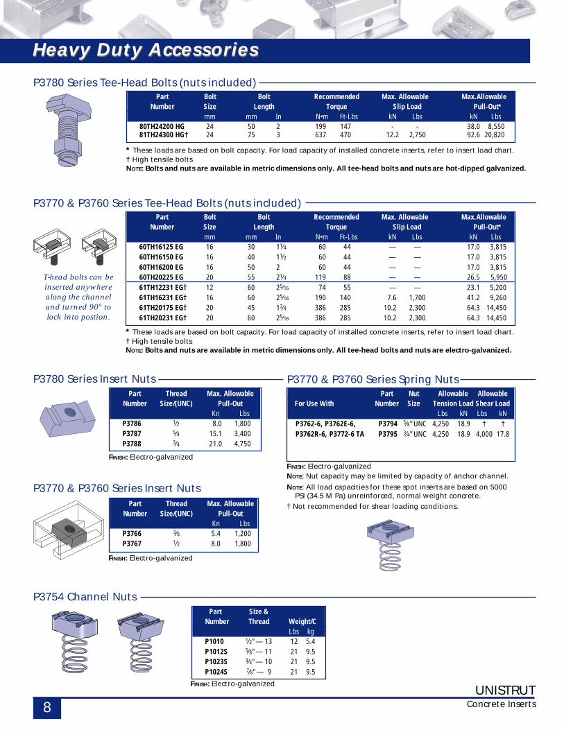
T-head bolts can beinserted anywherealong the channeland turned 90° tolock into postion.
* These loads are based on bolt capacity. For load capacity of installed concrete inserts, refer to insert load chart.† High tensile boltsNOTE: Bolts and nuts are available in metric dimensions only. All tee-head bolts and nuts are hot-dipped galvanized.
Part Bolt Bolt Recommended Max. Allowable Max.AllowableNumber Size Length Torque Slip Load Pull-Out*
mm mm In N•m Ft-Lbs kN Lbs kN Lbs80TH24200 HG 24 50 2 199 147 - - 38.0 8,55081TH24300 HG† 24 75 3 637 470 12.2 2,750 92.6 20,820
P3780 Series Tee-Head Bolts (nuts included)
Part Bolt Bolt Recommended Max. Allowable Max.AllowableNumber Size Length Torque Slip Load Pull-Out*
mm mm In N•m Ft-Lbs kN Lbs kN Lbs60TH16125 EG 16 30 11⁄4 60 44 — — 17.0 3,81560TH16150 EG 16 40 11⁄2 60 44 — — 17.0 3,81560TH16200 EG 16 50 2 60 44 — — 17.0 3,81560TH20225 EG 20 55 21⁄4 119 88 — — 26.5 5,95061TH12231 EG† 12 60 25⁄16 74 55 — — 23.1 5,20061TH16231 EG† 16 60 25⁄16 190 140 7.6 1,700 41.2 9,26061TH20175 EG† 20 45 13⁄4 386 285 10.2 2,300 64.3 14,45061TH20231 EG† 20 60 25⁄16 386 285 10.2 2,300 64.3 14,450
* These loads are based on bolt capacity. For load capacity of installed concrete inserts, refer to insert load chart.† High tensile boltsNOTE: Bolts and nuts are available in metric dimensions only. All tee-head bolts and nuts are electro-galvanized.
P3770 & P3760 Series Tee-Head Bolts (nuts included)
P3754 Channel NutsPart Size &
Number Thread Weight/CLbs kg
P1010 1⁄2" — 13 12 5.4P1012S 5⁄8" — 11 21 9.5P1023S 3⁄4" — 10 21 9.5P1024S 7⁄8" — 9 21 9.5
FINISH: Electro-galvanized
Part Thread Max. AllowableNumber Size/(UNC) Pull-Out
Kn LbsP3786 1⁄2 8.0 1,800P3787 5⁄8 15.1 3,400P3788 3⁄4 21.0 4,750
P3780 Series Insert Nuts
FINISH: Electro-galvanized
Part Thread Max. AllowableNumber Size/(UNC) Pull-Out
Kn LbsP3766 3⁄8 5.4 1,200P3767 1⁄2 8.0 1,800
P3770 & P3760 Series Insert Nuts
FINISH: Electro-galvanized
FINISH: Electro-galvanizedNOTE: Nut capacity may be limited by capacity of anchor channel.
NOTE: All load capacities for these spot inserts are based on 5000PSI (34.5 M Pa) unreinforced, normal weight concrete.
† Not recommended for shear loading conditions.
Part Nut Allowable AllowableFor Use With Number Size Tension Load Shear Load
Lbs kN Lbs kNP3762-6, P3762E-6, P3794 5⁄8" UNC 4,250 18.9 † †P3762R-6, P3772-6 TA P3795 3⁄4" UNC 4,250 18.9 4,000 17.8
P3770 & P3760 Series Spring Nuts
Heavy Duty AccessoriesHeavy Duty Accessories
UNISTRUTConcrete Inserts 9
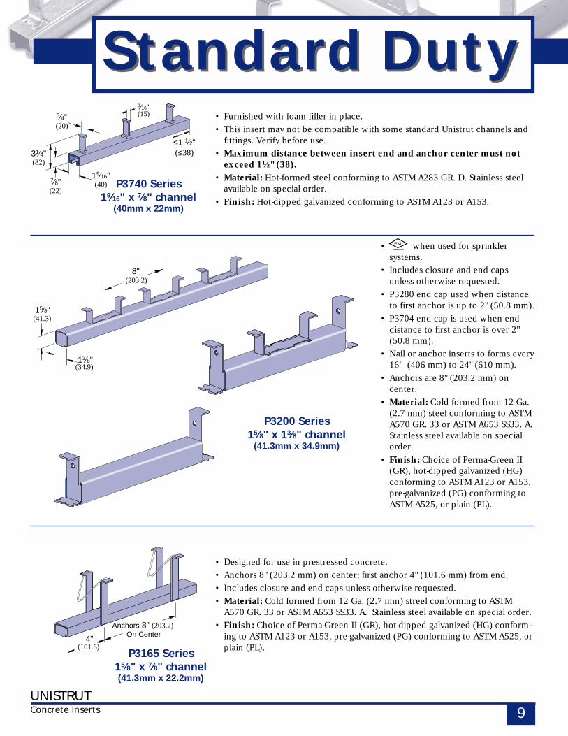
Standard DutyStandard Duty(15)9⁄16"
≤1 1⁄2"(≤38)
7⁄8"(22)
31⁄4"(82)
19⁄16"(40)
3⁄4"(20)
P3740 Series19⁄16" x 7⁄8" channel
(40mm x 22mm)
8"(203.2)
13⁄8"(34.9)
15⁄8"(41.3)
P3200 Series15⁄8" x 13⁄8" channel
(41.3mm x 34.9mm)
(101.6)4"
Anchors 8" (203.2) On Center
P3165 Series15⁄8" x 7⁄8" channel(41.3mm x 22.2mm)
• when used for sprinklersystems.
• Includes closure and end capsunless otherwise requested.
• P3280 end cap used when distanceto first anchor is up to 2" (50.8 mm).
• P3704 end cap is used when enddistance to first anchor is over 2"(50.8 mm).
• Nail or anchor inserts to forms every16" (406 mm) to 24" (610 mm).
• Anchors are 8" (203.2 mm) oncenter.
• Material: Cold formed from 12 Ga.(2.7 mm) steel conforming to ASTMA570 GR. 33 or ASTM A653 SS33. A.Stainless steel available on specialorder.
• Finish: Choice of Perma-Green II(GR), hot-dipped galvanized (HG)conforming to ASTM A123 or A153,pre-galvanized (PG) conforming toASTM A525, or plain (PL).
FM
• Furnished with foam filler in place.
• This insert may not be compatible with some standard Unistrut channels andfittings. Verify before use.
• Maximum distance between insert end and anchor center must notexceed 11⁄2" (38).
• Material: Hot-formed steel conforming to ASTM A283 GR. D. Stainless steelavailable on special order.
• Finish: Hot-dipped galvanized conforming to ASTM A123 or A153.
• Designed for use in prestressed concrete.
• Anchors 8" (203.2 mm) on center; first anchor 4" (101.6 mm) from end.
• Includes closure and end caps unless otherwise requested.
• Material: Cold formed from 12 Ga. (2.7 mm) streel conforming to ASTMA570 GR. 33 or ASTM A653 SS33. A. Stainless steel available on special order.
• Finish: Choice of Perma-Green II (GR), hot-dipped galvanized (HG) conform-ing to ASTM A123 or A153, pre-galvanized (PG) conforming to ASTM A525, orplain (PL).
UNISTRUTConcrete Inserts10
33⁄4"A
Load
BLoad
(95.3)
11⁄16"(18)
0.10"(2)
1⁄4"(6)7⁄8"(22)
31⁄4"
(82)
19⁄16"(40)
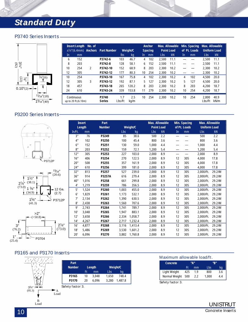
Insert Part Max. Allowable Min. Spacing Max. AllowableLength Number Weight/C Point Load of Pt. Loads Uniform Load
In/Ft. mm Lbs kg Lbs kN In mm Lbs kN3" 76 P3249 85 38.6 500 2.2 — — 500 2.24" 102 P3250 100 45.4 800 3.6 — — 800 3.66" 152 P3251 130 59.0 1,000 4.4 — — 1,000 4.48" 203 P3252 159 72.1 1,200 5.4 — — 1,200 5.4
12" 305 P3253 227 103.0 2,000 8.9 — — 2,000 8.916" 406 P3254 270 122.5 2,000 8.9 12 305 4,000 17.820" 508 P3255 357 161.9 2,000 8.9 12 305 4,000 17.824" 610 P3256 399 181.0 2,000 8.9 12 305 4,000 17.832" 813 P3257 527 239.0 2,000 8.9 12 305 2,000/Ft. 29.2/M36" 914 P3257A 616 279.4 2,000 8.9 12 305 2,000/Ft. 29.2/M40" 1,016 P3258 661 299.8 2,000 8.9 12 305 2,000/Ft. 29.2/M4' 1,219 P3259 786 356.5 2,000 8.9 12 305 2,000/Ft. 29.2/M5' 1,524 P3260 1,003 455.0 2,000 8.9 12 305 2,000/Ft. 29.2/M6' 1,829 P3261 1,173 532.1 2,000 8.9 12 305 2,000/Ft. 29.2/M7' 2,134 P3262 1,390 630.5 2,000 8.9 12 305 2,000/Ft. 29.2/M8' 2,438 P3263 1,560 707.6 2,000 8.9 12 305 2,000/Ft. 29.2/M9' 2,743 P3264 1,741 789.7 2,000 8.9 12 305 2,000/Ft. 29.2/M
10' 3,048 P3265 1,947 883.1 2,000 8.9 12 305 2,000/Ft. 29.2/M12' 3,658 P3266 2,334 1,058.7 2,000 8.9 12 305 2,000/Ft. 29.2/M14' 4,267 P3267 2,717 1,232.4 2,000 8.9 12 305 2,000/Ft. 29.2/M16' 4,877 P3268 3,116 1,413.4 2,000 8.9 12 305 2,000/Ft. 29.2/M18' 5,486 P3269 3,530 1,601.2 2,000 8.9 12 305 2,000/Ft. 29.2/M20' 6,096 P3270 3,882 1,760.8 2,000 8.9 12 305 2,000/Ft. 29.2/M
P3200 Series Inserts
27⁄8"(73.0)
11⁄2"(38.1)
15⁄8"(41.3)
12 Ga.(2.7)
(20.6)13⁄16"
P3712P
1 3⁄8"(34.9)
3"(76.2)
>2"(>50.8)
27⁄8"(73.0)
P37041"(25.4)
P3712P
Insert Length No. of Anchor Max. Allowable Min. Spacing Max. Allowable±1⁄4" (6.4mm) Anchors Part Number Weight/C Spacing Point Load of Pt. Loads Uniform LoadIn mm lbs kg In mm Lbs kN In mm Lbs kN6 152 P3742-6 103 46.7 4 102 2,500 11.1 — — 2,500 11.18 203 P3742-8 128 58.1 6 152 2,500 11.1 — — 2,500 11.1
10 254 2 P3742-10 152 68.9 8 203 2,300 10.2 — — 2,300 10.212 305 P3742-12 177 80.3 10 254 2,300 10.2 — — 2,300 10.210 254 P3743-10 167 75.8 4 102 2,300 10.2 4 102 4,500 20.012 305 3 P3743-12 192 87.1 5 127 2,300 10.2 5 127 4,500 20.018 457 P3743-18 265 120.2 8 203 2,300 10.2 8 203 4,200 18.724 610 P3743-24 339 153.8 11 279 2,300 10.2 10 254 4,200 18.7
Continuous P3740 1.7 2.5 10 254 2,300 10.2 10 254 2,800 40.9up to 20 ft.(6.10m) Series Lbs/Ft kg/m Lbs/Ft kN/m
Concrete "A" "B"Ft mm Lbs kg
Light Weight 425 1.9 800 3.6Normal Weight 500 2.2 1,000 4.4
Maximum allowable load/ft.
Safety factor 3.
P3165 and P3170 Inserts
P3740 Series Inserts
PartNumber Length Weight/C
Ft mm Lbs kgP3165 10 3,048 1,650 748.4P3170 20 6,096 3,280 1,487.8
Safety factor 3.
Standard DutyStandard Duty
UNISTRUTConcrete Inserts 11
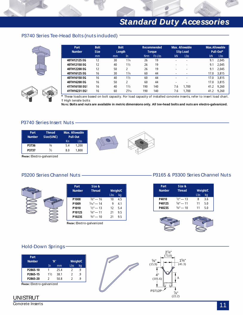
P3740 Series Tee-Head Bolts (nuts included)
Part Size &Number Thread Weight/C
Lbs kgP1008 3⁄8" — 16 10 4.5P1009 7⁄16" — 14 9 4.1P1010 1⁄2" — 13 12 5.4P1012S 5⁄8" — 11 21 9.5P1023S 3⁄4" — 10 21 9.5
P3200 Series Channel Nuts
FINISH: Electro-galvanized
Part Thread Max. AllowableNumber Size/(UNC) Pull-Out
Kn LbsP3736 3⁄8 5.4 1,200P3737 1⁄2 8.0 1,800
P3740 Series Insert Nuts
FINISH: Electro-galvanized
A
(41.3)15⁄8"
(73.0)27⁄8"
(15.9)
5⁄8"
(101.6)4"
(22.2)7⁄8"
P3712P
Part Size &Number Thread Weight/C
Lbs kgP4010 1⁄2" — 13 8 3.6P4012S 5⁄8" — 11 11 5.0P4023S 3⁄4" — 10 11 5.0
P3165 & P3300 Series Channel Nuts
PartNumber "A" Weight/C
In mm Lbs kgP2865-10 1 25.4 2 .9P2865-15 11⁄2 38.1 2 .9P2865-20 2 50.8 2 .9
Hold-Down Springs
FINISH: Electro-galvanized
Part Bolt Bolt Recommended Max. Allowable Max.AllowableNumber Size Length Torque Slip Load Pull-Out*
mm mm In N•m Ft-Lbs kN Lbs kN Lbs40TH12125 EG 12 30 11⁄4 26 19 - - 9.1 2,04540TH12150 EG 12 40 11⁄2 26 19 - - 9.1 2,04540TH12200 EG 12 50 2 26 19 - - 9.1 2,04540TH16125 EG 16 30 11⁄4 60 44 - - 17.0 3,81540TH16150 EG 16 40 11⁄2 60 44 - - 17.0 3,81540TH16200 EG 16 50 2 60 44 - - 17.0 3,81541TH16150 EG† 16 40 11⁄2 190 140 7.6 1,700 41.2 9,26041TH16231 EG† 16 60 25⁄16 190 140 7.6 1,700 41.2 9,260
* These loads are based on bolt capacity. For load capacity of installed concrete inserts, refer to insert load chart.† High tensile boltsNOTE: Bolts and nuts are available in metric dimensions only. All tee-head bolts and nuts are electro-galvanized.
Standard Duty AccessoriesStandard Duty Accessories
UNISTRUTConcrete Inserts12
27⁄16"(61.9)
1"(25.4)
(60.3)23⁄8"
P3703
>2"(>50.8)
P3380
≤2"(≤50.8)1⁄8"
(3.2)
(22.2)7⁄8"
11⁄2"
(60.3)23⁄8" (38.1)
15⁄8"(41.3)
12 Ga.
(20.6)
(2.7)
13⁄16"
P3712P
P3712P
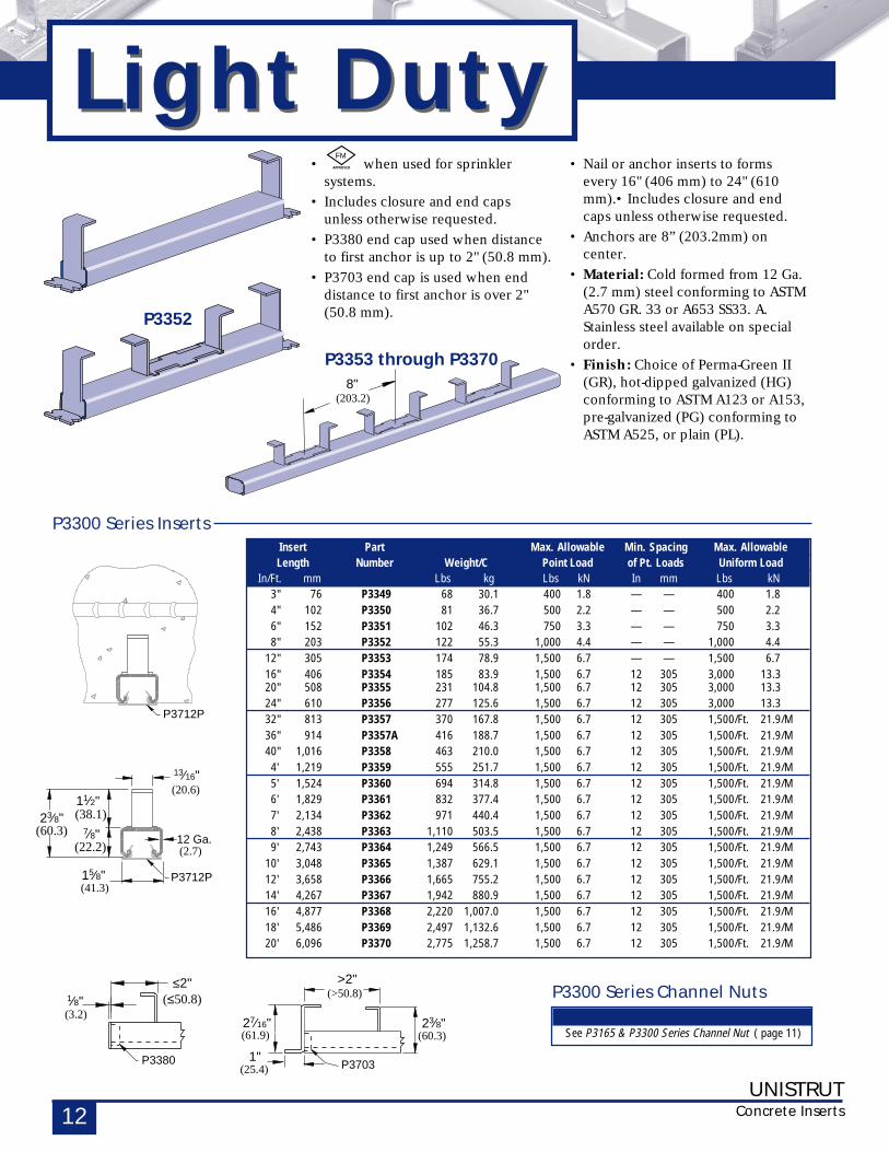
Insert Part Max. Allowable Min. Spacing Max. AllowableLength Number Weight/C Point Load of Pt. Loads Uniform Load
In/Ft. mm Lbs kg Lbs kN In mm Lbs kN3" 76 P3349 68 30.1 400 1.8 — — 400 1.84" 102 P3350 81 36.7 500 2.2 — — 500 2.26" 152 P3351 102 46.3 750 3.3 — — 750 3.38" 203 P3352 122 55.3 1,000 4.4 — — 1,000 4.4
12" 305 P3353 174 78.9 1,500 6.7 — — 1,500 6.716" 406 P3354 185 83.9 1,500 6.7 12 305 3,000 13.320" 508 P3355 231 104.8 1,500 6.7 12 305 3,000 13.324" 610 P3356 277 125.6 1,500 6.7 12 305 3,000 13.332" 813 P3357 370 167.8 1,500 6.7 12 305 1,500/Ft. 21.9/M36" 914 P3357A 416 188.7 1,500 6.7 12 305 1,500/Ft. 21.9/M40" 1,016 P3358 463 210.0 1,500 6.7 12 305 1,500/Ft. 21.9/M4' 1,219 P3359 555 251.7 1,500 6.7 12 305 1,500/Ft. 21.9/M5' 1,524 P3360 694 314.8 1,500 6.7 12 305 1,500/Ft. 21.9/M6' 1,829 P3361 832 377.4 1,500 6.7 12 305 1,500/Ft. 21.9/M7' 2,134 P3362 971 440.4 1,500 6.7 12 305 1,500/Ft. 21.9/M8' 2,438 P3363 1,110 503.5 1,500 6.7 12 305 1,500/Ft. 21.9/M9' 2,743 P3364 1,249 566.5 1,500 6.7 12 305 1,500/Ft. 21.9/M
10' 3,048 P3365 1,387 629.1 1,500 6.7 12 305 1,500/Ft. 21.9/M12' 3,658 P3366 1,665 755.2 1,500 6.7 12 305 1,500/Ft. 21.9/M14' 4,267 P3367 1,942 880.9 1,500 6.7 12 305 1,500/Ft. 21.9/M16' 4,877 P3368 2,220 1,007.0 1,500 6.7 12 305 1,500/Ft. 21.9/M18' 5,486 P3369 2,497 1,132.6 1,500 6.7 12 305 1,500/Ft. 21.9/M20' 6,096 P3370 2,775 1,258.7 1,500 6.7 12 305 1,500/Ft. 21.9/M
P3300 Series Inserts
P3300 Series Channel Nuts
See P3165 & P3300 Series Channel Nut ( page 11)
• Nail or anchor inserts to formsevery 16" (406 mm) to 24" (610mm).• Includes closure and endcaps unless otherwise requested.
• Anchors are 8” (203.2mm) oncenter.
• Material: Cold formed from 12 Ga.(2.7 mm) steel conforming to ASTMA570 GR. 33 or A653 SS33. A.Stainless steel available on specialorder.
• Finish: Choice of Perma-Green II(GR), hot-dipped galvanized (HG)conforming to ASTM A123 or A153,pre-galvanized (PG) conforming toASTM A525, or plain (PL).
P3352
FM
8"(203.2)
P3353 through P3370
• when used for sprinklersystems.
• Includes closure and end capsunless otherwise requested.
• P3380 end cap used when distanceto first anchor is up to 2" (50.8 mm).
• P3703 end cap is used when enddistance to first anchor is over 2"(50.8 mm).
Light DutyLight Duty
UNISTRUTConcrete Inserts 13
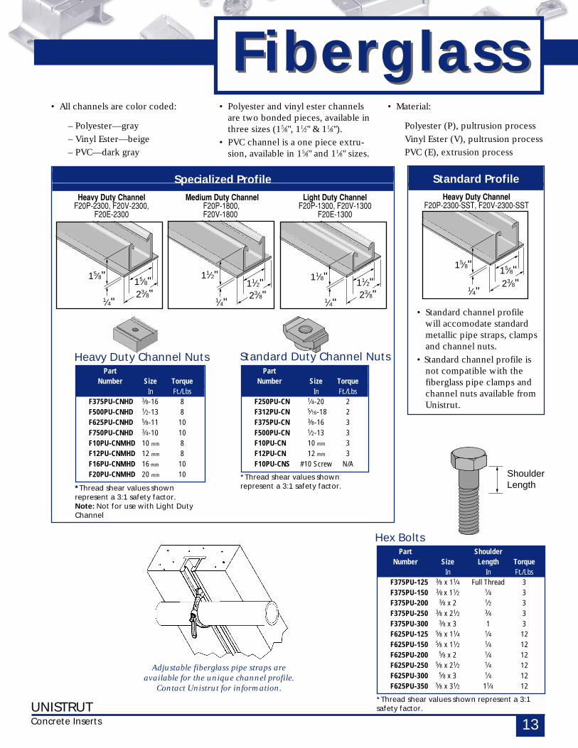
Standard Profile
Heavy Duty ChannelF20P-2300-SST, F20V-2300-SST
Specialized Profile
Heavy Duty Channel Medium Duty Channel Light Duty ChannelF20P-2300, F20V-2300, F20P-1800, F20P-1300, F20V-1300
F20E-2300 F20V-1800 F20E-1300
FiberglassFiberglass
ShoulderLength
• All channels are color coded:
– Polyester—gray
– Vinyl Ester—beige
– PVC—dark gray
• Standard channel profilewill accomodate standardmetallic pipe straps, clampsand channel nuts.
• Standard channel profile isnot compatible with thefiberglass pipe clamps andchannel nuts available fromUnistrut.
Hex BoltsPart Shoulder
Number Size Length TorqueIn In Ft./Lbs
F375PU-125 3⁄8 x 11⁄4 Full Thread 3F375PU-150 3⁄8 x 11⁄2 1⁄4 3F375PU-200 3⁄8 x 2 1⁄2 3F375PU-250 3⁄8 x 21⁄2 3⁄4 3F375PU-300 3⁄8 x 3 1 3F625PU-125 5⁄8 x 11⁄4 1⁄4 12F625PU-150 5⁄8 x 11⁄2 1⁄4 12F625PU-200 5⁄8 x 2 1⁄4 12F625PU-250 5⁄8 x 21⁄2 1⁄4 12F625PU-300 5⁄8 x 3 1⁄4 12F625PU-350 5⁄8 x 31⁄2 11⁄4 12
*Thread shear values shown represent a 3:1safety factor.
15⁄8"
1⁄4"
15⁄8"23⁄8"
11⁄2"
1⁄4"23⁄8"11⁄2" 11⁄8"
1⁄4"
11⁄2"23⁄8"
15⁄8"
1⁄4"
15⁄8"23⁄8"
• Polyester and vinyl ester channelsare two bonded pieces, available inthree sizes (15⁄8", 11⁄2" & 11⁄8").
• PVC channel is a one piece extru-sion, available in 15⁄8" and 11⁄8" sizes.
• Material:
Polyester (P), pultrusion process
Vinyl Ester (V), pultrusion process
PVC (E), extrusion process
Adjustable fiberglass pipe straps areavailable for the unique channel profile.
Contact Unistrut for information.
PartNumber Size Torque
In Ft./LbsF375PU-CNHD 3⁄8-16 8F500PU-CNHD 1⁄2-13 8F625PU-CNHD 5⁄8-11 10F750PU-CNHD 3⁄4-10 10F10PU-CNMHD 10 mm 8F12PU-CNMHD 12 mm 8F16PU-CNMHD 16 mm 10F20PU-CNMHD 20 mm 10
*Thread shear values shownrepresent a 3:1 safety factor.Note: Not for use with Light DutyChannel
Heavy Duty Channel NutsPart
Number Size TorqueIn Ft./Lbs
F250PU-CN 1⁄4-20 2F312PU-CN 5⁄16-18 2F375PU-CN 3⁄8-16 3F500PU-CN 1⁄2-13 3F10PU-CN 10 mm 3F12PU-CN 12 mm 3F10PU-CNS #10 Screw N/A
*Thread shear values shownrepresent a 3:1 safety factor.
Standard Duty Channel Nuts
UNISTRUTConcrete Inserts14
2 7⁄16"(61.9)
1 3⁄4"(44.5)
7⁄8"(22.2)
2 5⁄8"(66.7)
30°0.17π
20°0.11π
SwivelActionRange
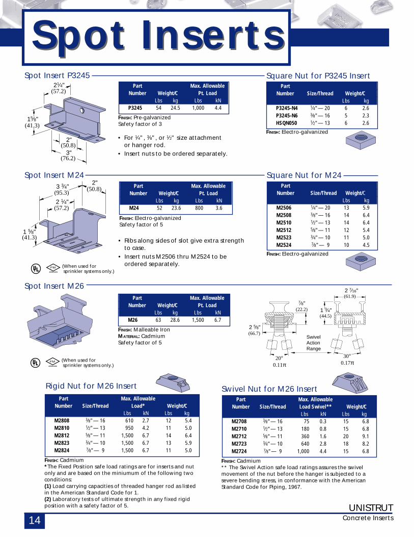
PartNumber Size/Thread Weight/C
Lbs kgM2506 1⁄4" — 20 13 5.9M2508 3⁄8" — 16 14 6.4M2510 1⁄2" — 13 14 6.4M2512 5⁄8" — 11 12 5.4M2523 3⁄4" — 10 11 5.0M2524 7⁄8" — 9 10 4.5
Square Nut for M24
FINISH: Electro-galvanized
PartNumber Size/Thread Weight/C
Lbs kgP3245-N4 1⁄4" — 20 6 2.6P3245-N6 3⁄8" — 16 5 2.3HSQN050 1⁄2" — 13 6 2.6
Square Nut for P3245 Insert
FINISH: Electro-galvanized
Part Max. AllowableNumber Weight/C Pt. Load
Lbs kg Lbs kNM24 52 23.6 800 3.6
Spot Insert M24
FINISH: Electro-galvanizedSafety factor of 5
Part Max. AllowableNumber Weight/C Pt. Load
Lbs kg Lbs kNM26 63 28.6 1,500 6.7
Spot Insert M26
FINISH: Malleable IronMATERIAL: CadmiumSafety factor of 5
2 1⁄4"(57.2)
3 3⁄4"(95.3)
2"(50.8)
1 5⁄8"(41.3)
2"(50.8)
21⁄4"(57.2)
3"(76.2)
15⁄8"(41.3)
• Ribs along sides of slot give extra strengthto case.
• Insert nuts M2506 thru M2524 to beordered separately.
• For 1⁄4", 3⁄8", or 1⁄2" size attachmentor hanger rod.
• Insert nuts to be ordered separately.
Spot Insert P3245Part Max. Allowable
Number Weight/C Pt. LoadLbs kg Lbs kN
P3245 54 24.5 1,000 4.4
FINISH: Pre-galvanizedSafety factor of 3
(When used for sprinkler systems only.)
FM
(When used for sprinkler systems only.)
FM
Part Max. AllowableNumber Size/Thread Load Swivel** Weight/C
Lbs kN Lbs kgM2708 3⁄8" — 16 75 0.3 15 6.8M2710 1⁄2" — 13 180 0.8 15 6.8M2712 5⁄8" — 11 360 1.6 20 9.1M2723 3⁄4" — 10 640 2.8 18 8.2M2724 7⁄8" — 9 1,000 4.4 15 6.8
Swivel Nut for M26 Insert
FINISH: Cadmium** The Swivel Action safe load ratings assures the swivelmovement of the nut before the hanger is subjected to asevere bending stress, in conformance with the AmericanStandard Code for Piping, 1967.
Part Max. AllowableNumber Size/Thread Load* Weight/C
Lbs kN Lbs kgM2808 3⁄8" — 16 610 2.7 12 5.4M2810 1⁄2" — 13 950 4.2 11 5.0M2812 5⁄8" — 11 1,500 6.7 14 6.4M2823 3⁄4" — 10 1,500 6.7 13 5.9M2824 7⁄8" — 9 1,500 6.7 11 5.0
FINISH: Cadmium*The Fixed Position safe load ratings are for inserts and nutonly and are based on the miniumum of the following twoconditions:(1) Load carrying capacities of threaded hanger rod as listedin the American Standard Code for 1.(2) Laboratory tests of ultimate strength in any fixed rigidposition with a safety factor of 5.
Rigid Nut for M26 Insert
Spot InsertsSpot Inserts
UNISTRUTConcrete Inserts 15
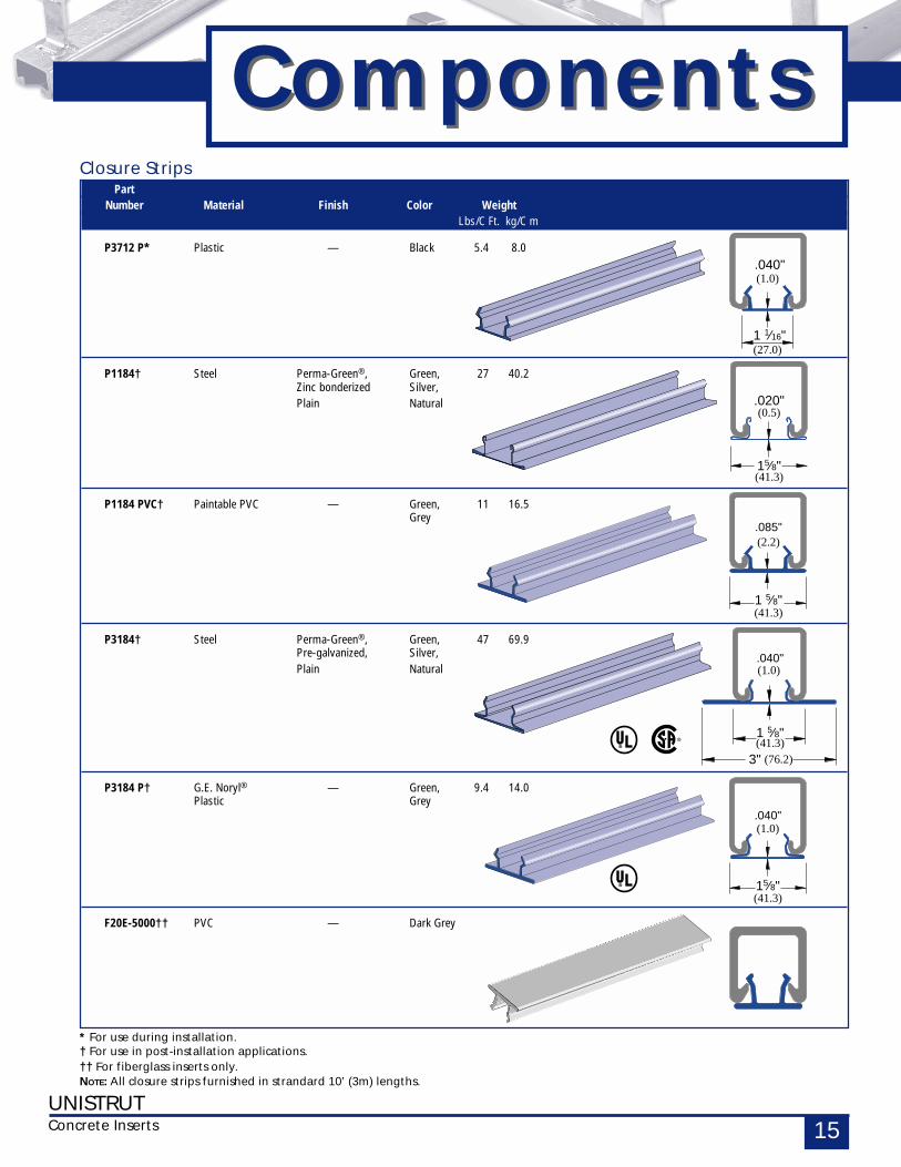
PartNumber Material Finish Color Weight
Lbs/C Ft. kg/C m
P3712 P* Plastic — Black 5.4 8.0
P1184† Steel Perma-Green®, Green, 27 40.2Zinc bonderized Silver,Plain Natural
P1184 PVC† Paintable PVC — Green, 11 16.5Grey
P3184† Steel Perma-Green®, Green, 47 69.9Pre-galvanized, Silver,Plain Natural
P3184 P† G.E. Noryl® — Green, 9.4 14.0Plastic Grey
F20E-5000†† PVC — Dark Grey
ComponentsComponents
* For use during installation.† For use in post-installation applications.†† For fiberglass inserts only.NOTE: All closure strips furnished in strandard 10’ (3m) lengths.
Closure Strips
.020"
15⁄8"(41.3)
(0.5)
.040"
15⁄8"
(1.0)
(41.3)
.085"
1 5⁄8"
(2.2)
(41.3)
.040"
1 1⁄16"
(1.0)
(27.0)
.040"
1 5⁄8"
(1.0)
(41.3)(76.2)3"
UNISTRUTConcrete Inserts16
A
27⁄16"(61.9)
P3300
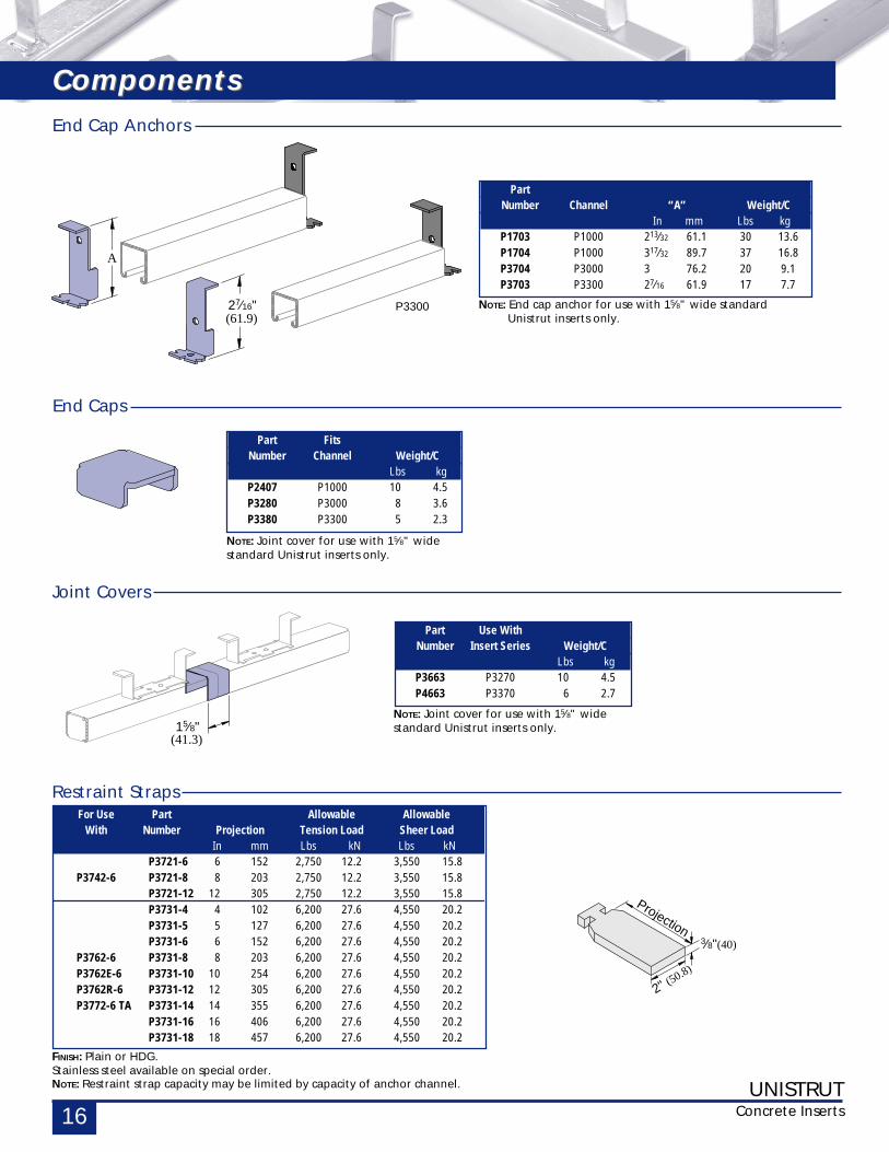
For Use Part Allowable AllowableWith Number Projection Tension Load Sheer Load
In mm Lbs kN Lbs kNP3721-6 6 152 2,750 12.2 3,550 15.8
P3742-6 P3721-8 8 203 2,750 12.2 3,550 15.8P3721-12 12 305 2,750 12.2 3,550 15.8P3731-4 4 102 6,200 27.6 4,550 20.2P3731-5 5 127 6,200 27.6 4,550 20.2P3731-6 6 152 6,200 27.6 4,550 20.2
P3762-6 P3731-8 8 203 6,200 27.6 4,550 20.2P3762E-6 P3731-10 10 254 6,200 27.6 4,550 20.2P3762R-6 P3731-12 12 305 6,200 27.6 4,550 20.2P3772-6 TA P3731-14 14 355 6,200 27.6 4,550 20.2
P3731-16 16 406 6,200 27.6 4,550 20.2P3731-18 18 457 6,200 27.6 4,550 20.2
Restraint Straps
FINISH: Plain or HDG.Stainless steel available on special order.NOTE: Restraint strap capacity may be limited by capacity of anchor channel.
15⁄8"(41.3)
Part Use WithNumber Insert Series Weight/C
Lbs kgP3663 P3270 10 4.5P4663 P3370 6 2.7
Joint Covers
NOTE: Joint cover for use with 15⁄8" widestandard Unistrut inserts only.
NOTE: Joint cover for use with 15⁄8" widestandard Unistrut inserts only.
Part FitsNumber Channel Weight/C
Lbs kgP2407 P1000 10 4.5P3280 P3000 8 3.6P3380 P3300 5 2.3
End Caps
End Cap Anchors
PartNumber Channel “A” Weight/C
In mm Lbs kgP1703 P1000 213⁄32 61.1 30 13.6P1704 P1000 317⁄32 89.7 37 16.8P3704 P3000 3 76.2 20 9.1P3703 P3300 27⁄16 61.9 17 7.7
NOTE: End cap anchor for use with 15⁄8" wide standard Unistrut inserts only.
2" (50.8)
Projection3⁄8"(40)
ComponentsComponents
UNISTRUTConcrete Inserts 17
PART I - GENERAL
1.01 SCOPE OF WORKA. Provide all Unistut Metal Framing
material, fittings and relatedaccessories (Strut System) asindicated on the Contract Drawings.
B. Provide all labor, supervision,engineering, and fabricationrequired for installation of the StrutSystem in accordance with theContractDrawings and as specified herein.
C. Related work specified elsewhere.
1.02 QUALITY ASSURANCEA. Manufacturer’s qualifications:
1. The manufacturer shall nothave had less than 10 year’sexperience in manufacturingStrut Systems.
2. The manufacturer must certifyin writing all componentssupplied have been produced inaccordance with an establishedquality assurance program.
B. Installer’s qualifications:1. Installer must be a Unistrut
trained manufacturer’s autho-rized representative/installerwith not less than 5 yearsexperience inthe installation of Strut Systemsof this size and conformation.
2. All Strut System componentsmust be supplied by a singlemanufacturer.
C. Standards:1. Work shall meet the require-
ments of the following stan-dards.
Federal, State and Local codes.American Iron and Steel Institute(AISI) Specification for theDesign of Cold-Formed SteelStructural Members August 19,1986Edition, December 11, 1989Addendum.
American Society for TestingAnd Materials (ASTM).
1.03 SUBMITTALSA. Structural Calculations and Shop
Drawings1. Submit structural calculations
for approval by the projectengineer. Calculations mayinclude, but are not limited to:a. Description of design
criteria.b. Stress and deflection analysis.c. Selection of Unistrut framing
members, fittings, andaccessories.
Standard 595a color number14109 (dark limit V-). Finish towithstand minimum 400 hourssalt spray when tested inaccordance with ASTM B 117.
2. ELECTRO-GALVANIZED (EG)Electrolytically zinc coated perASTM B 633 Type III SC 1
3. PRE-GALVANIZED (PG)Zinc coated by hot-dippedprocess prior to roll forming.The zinc weight shall be G90conformingto ASTM A 653.
4. HOT-DIPPED GALVANIZED(HG)Zinc coated after all manufactur-ing operations are complete.Coating shall conform to ASTM A123 orA 153.
5. SPECIAL COATING / MATERIAL(Describe as applicable)
PART 3 - EXECUTION
3.01 EXAMINATIONA. The installer shall inspect the work
area prior to installation. If workarea conditions are unsatisfactory,installation shall not proceed untilsatisfactory corrections are com-pleted.
3.02 INSTALLATIONA. Installation shall be accomplished by
a fully trained manufacturerauthorized installer.
B. Set Strut System components intofinal position true to line, level andplumb, in accordance withapproved shop drawings.
C. Anchor material firmly in place.Tighten all connections to theirrecommended torques.
3.03 CLEANUPA. Upon completion of this section of
work, remove all protective wrapsand debris. Repair any damage dueto installation of this section ofwork.
3.04 PROTECTIONA. During installation, it shall be the
responsibility of the installer toprotect this work from damage.
B. Upon completion of this scope ofwork, it shall become theresponsibility of the generalcontractor to protect this workfrom damage during the remainderof construction on the project anduntil substantial completion.
2. Submit all shop/assemblydrawings necessary to com-pletely install the Strut System incompliance withthe Contract Drawings.
3. Submit all pertinent manufactur-ers published data.
1.04 PRODUCT DELIVERY,STORAGE, AND HANDLING
A. All material is to be delivered tothe work site in original factorypackaging to avoid damage to thefinish.
B. Upon delivery to the work site,all components shall be protectedfrom the elements by a shelter orother covering.
1.05 GUARANTEEA. Separate guarantees shall be issued
from the erector and manufacturer,valid for a period of 1 year, againstany defects that may arise from theinstallation or manufacture of theStrut System components.
PART 2 - PRODUCTS
2.01 ACCEPTABLE MANUFACTURERSA. All Strut System components shall
be as manufactured by UNISTRUTCORPORATION or approved equalas determined by the Architect orEngineer of record in writing 10days prior to bid date.
2.02 MATERIALSA. All channel members shall be
fabricated from structural gradesteel conforming to one of thefollowing ASTM specifications:A 570 GR 33, A 653 SS 33
B. All fittings shall be fabricated fromsteel conforming to one of thefollowing ASTM specifications:A 575, A 576, A 36 or A 635
C. SubstitutionsAny substitutions of product ormanufacturer must be approved inwriting ten days prior to bid date,by Architect or Engineer of record.
2.03 FINISHESA. Strut System components shall be
finished in accordance with one ofthe following standards:1. PERMA-GREEN® II (GR)
Rust inhibiting acrylic enamelpaint applied by electro-deposition, after cleaning andphosphating, and thoroughlybaked. Color is per Federal
GeneralSpecifications
GeneralSpecifications
UNISTRUTConcrete Inserts18
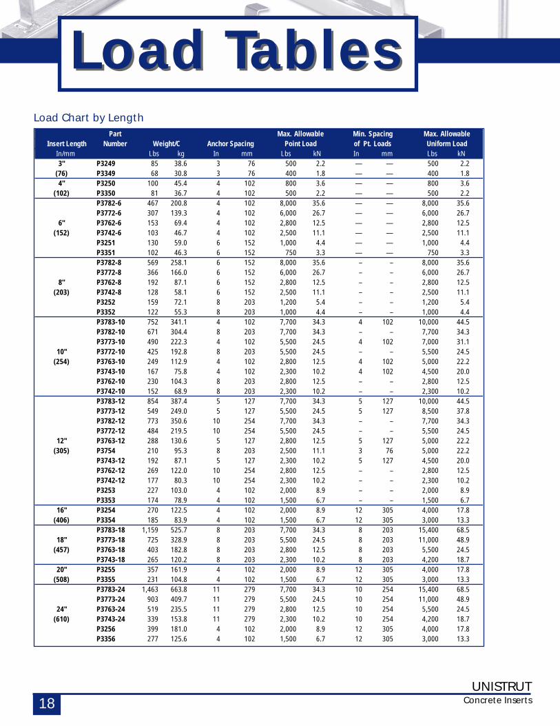
Load TablesLoad TablesPart Max. Allowable Min. Spacing Max. Allowable
Insert Length Number Weight/C Anchor Spacing Point Load of Pt. Loads Uniform LoadIn/mm Lbs kg In mm Lbs kN In mm Lbs kN3" P3249 85 38.6 3 76 500 2.2 — — 500 2.2
(76) P3349 68 30.8 3 76 400 1.8 — — 400 1.84" P3250 100 45.4 4 102 800 3.6 — — 800 3.6
(102) P3350 81 36.7 4 102 500 2.2 — — 500 2.2P3782-6 467 200.8 4 102 8,000 35.6 — — 8,000 35.6P3772-6 307 139.3 4 102 6,000 26.7 — — 6,000 26.7
6" P3762-6 153 69.4 4 102 2,800 12.5 — — 2,800 12.5(152) P3742-6 103 46.7 4 102 2,500 11.1 — — 2,500 11.1
P3251 130 59.0 6 152 1,000 4.4 — — 1,000 4.4P3351 102 46.3 6 152 750 3.3 — — 750 3.3P3782-8 569 258.1 6 152 8,000 35.6 – – 8,000 35.6P3772-8 366 166.0 6 152 6,000 26.7 – – 6,000 26.7
8" P3762-8 192 87.1 6 152 2,800 12.5 – – 2,800 12.5(203) P3742-8 128 58.1 6 152 2,500 11.1 – – 2,500 11.1
P3252 159 72.1 8 203 1,200 5.4 – – 1,200 5.4P3352 122 55.3 8 203 1,000 4.4 – – 1,000 4.4P3783-10 752 341.1 4 102 7,700 34.3 4 102 10,000 44.5P3782-10 671 304.4 8 203 7,700 34.3 – – 7,700 34.3P3773-10 490 222.3 4 102 5,500 24.5 4 102 7,000 31.1
10" P3772-10 425 192.8 8 203 5,500 24.5 – – 5,500 24.5(254) P3763-10 249 112.9 4 102 2,800 12.5 4 102 5,000 22.2
P3743-10 167 75.8 4 102 2,300 10.2 4 102 4,500 20.0P3762-10 230 104.3 8 203 2,800 12.5 – – 2,800 12.5P3742-10 152 68.9 8 203 2,300 10.2 – – 2,300 10.2P3783-12 854 387.4 5 127 7,700 34.3 5 127 10,000 44.5P3773-12 549 249.0 5 127 5,500 24.5 5 127 8,500 37.8P3782-12 773 350.6 10 254 7,700 34.3 – – 7,700 34.3P3772-12 484 219.5 10 254 5,500 24.5 – – 5,500 24.5
12" P3763-12 288 130.6 5 127 2,800 12.5 5 127 5,000 22.2(305) P3754 210 95.3 8 203 2,500 11.1 3 76 5,000 22.2
P3743-12 192 87.1 5 127 2,300 10.2 5 127 4,500 20.0P3762-12 269 122.0 10 254 2,800 12.5 – – 2,800 12.5P3742-12 177 80.3 10 254 2,300 10.2 – – 2,300 10.2P3253 227 103.0 4 102 2,000 8.9 – – 2,000 8.9P3353 174 78.9 4 102 1,500 6.7 – – 1,500 6.7
16" P3254 270 122.5 4 102 2,000 8.9 12 305 4,000 17.8(406) P3354 185 83.9 4 102 1,500 6.7 12 305 3,000 13.3
P3783-18 1,159 525.7 8 203 7,700 34.3 8 203 15,400 68.518" P3773-18 725 328.9 8 203 5,500 24.5 8 203 11,000 48.9
(457) P3763-18 403 182.8 8 203 2,800 12.5 8 203 5,500 24.5P3743-18 265 120.2 8 203 2,300 10.2 8 203 4,200 18.7
20" P3255 357 161.9 4 102 2,000 8.9 12 305 4,000 17.8(508) P3355 231 104.8 4 102 1,500 6.7 12 305 3,000 13.3
P3783-24 1,463 663.8 11 279 7,700 34.3 10 254 15,400 68.5P3773-24 903 409.7 11 279 5,500 24.5 10 254 11,000 48.9
24" P3763-24 519 235.5 11 279 2,800 12.5 10 254 5,500 24.5(610) P3743-24 339 153.8 11 279 2,300 10.2 10 254 4,200 18.7
P3256 399 181.0 4 102 2,000 8.9 12 305 4,000 17.8P3356 277 125.6 4 102 1,500 6.7 12 305 3,000 13.3
Load Chart by Length
UNISTRUTConcrete Inserts 19
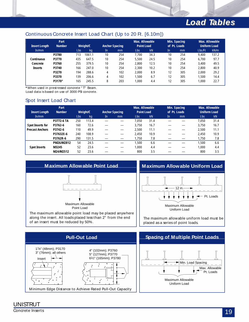
Part Max. Allowable Min. Spacing Max. AllowableInsert Length Number Weight/C Anchor Spacing Point Load of Pt. Loads Uniform Load
In/mm Lbs kg In mm Lbs kN In mm Lbs/Ft kN/mP3780 713 1061.1 10 254 7,700 34.3 10 254 9,400 137.2
Continuous P3770 435 647.5 10 254 5,500 24.5 10 254 6,700 97.7Concrete P3760 255 379.5 10 254 2,800 12.5 10 254 3,400 49.5Inserts P3740 166 247.0 10 254 2,300 10.2 10 254 2,800 40.9
P3270 194 288.6 4 102 2,000 8.9 12 305 2,000 29.2P3370 139 206.6 4 102 1,500 6.7 12 305 1,500 14.4P3170* 165 245.5 8 203 1,000 4.4 12 305 1,000 22.7
Continuous Concrete Insert Load Chart (Up to 20 Ft. [6.10m])
*When used in prestressed concrete “T” Beam.Load data is based on use of 3000 PSI concrete.
Part Max. Allowable Min. Spacing Max. AllowableInsert Length Number Weight/C Anchor Spacing Point Load of Pt. Loads Uniform Load
In/mm Lbs kg In mm Lbs kN In mm Lbs kNP3772-6 TA 250 113.4 — — 7,050 31.4 — — 7,050 31.4
Spot Inserts for P3762-6 160 72.6 — — 3,750 16.7 — — 3,750 16.7Precast Anchors P3742-6 110 49.9 — — 2,500 11.1 — — 2,500 11.1
P37632E-6 240 108.9 — — 2,450 10.9 — — 2,450 10.9P3762R-6 290 131.5 — — 1,750 7.8 — — 1,750 7.8PM26/M2812 54 24.5 — — 1,500 6.6 — — 1,500 6.6
Spot Inserts M3245 52 23.6 — — 1,000 4.4 — — 1,000 4.4M24/M2512 52 23.6 — — 800 3.5 — — 800 3.5
Spot Insert Load Chart
Load TablesLoad Tables
Pull-Out Load
Minimum Edge Distance to Achieve Rated Pull-Out Capacity
Maximum Allowable Point Load
The maximum allowable point load may be placed anywherealong the insert. All loads placed less than 2" from the endof an insert must be reduced by 50%.
Maximum Allowable Uniform Load
The maximum allowable uniform load must beplaced as a series of point loads.
Maximum AllowableUniform Load
Pt. Loads
12 in.
Spacing of Multiple Point Loads
Maximum AllowablePoint Load
Maximum AllowableUniform Load
Max. AllowablePt. Loads
Min. Load SpacingInsert
17⁄8" (48mm); P31703" (76mm); all others
4" (102mm); P37605" (127mm); P377061⁄2" (165mm); P3780
UCI-2 , Printed in USA, 5M, ©Copyright 1999, Unistrut Corporation
Unistrut Sales & Distribution1140 W. Thorndale Ave., Itasca, IL 60143
Tel: (800) 468-9510 • Fax: (630) 773-4214
Unistrut Manufacturing35660 Clinton Street, Wayne, MI 48184Tel: (800) 521-7730 • Fax: (734) 721-4106