programme book14-7-2006-d fileassoc. prof. dr. waluyo adi siswanto ... publication agung murti...
TRANSCRIPT
ISSN: 1823-3287
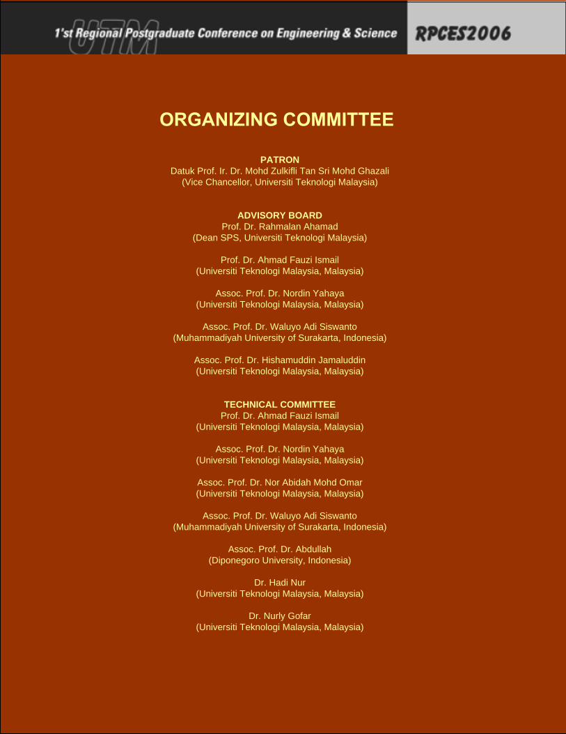
PATRONDatuk Prof. Ir. Dr. Mohd Zulkifli Tan Sri Mohd Ghazali
(Vice Chancellor, Universiti Teknologi Malaysia)
ADVISORY BOARDProf. Dr. Rahmalan Ahamad
(Dean SPS, Universiti Teknologi Malaysia)
Prof. Dr. Ahmad Fauzi Ismail(Universiti Teknologi Malaysia, Malaysia)
Assoc. Prof. Dr. Nordin Yahaya(Universiti Teknologi Malaysia, Malaysia)
Assoc. Prof. Dr. Waluyo Adi Siswanto(Muhammadiyah University of Surakarta, Indonesia)
Assoc. Prof. Dr. Hishamuddin Jamaluddin(Universiti Teknologi Malaysia, Malaysia)
TECHNICAL COMMITTEEProf. Dr. Ahmad Fauzi Ismail
(Universiti Teknologi Malaysia, Malaysia)
Assoc. Prof. Dr. Nordin Yahaya(Universiti Teknologi Malaysia, Malaysia)
Assoc. Prof. Dr. Nor Abidah Mohd Omar(Universiti Teknologi Malaysia, Malaysia)
Assoc. Prof. Dr. Waluyo Adi Siswanto(Muhammadiyah University of Surakarta, Indonesia)
Assoc. Prof. Dr. Abdullah(Diponegoro University, Indonesia)
Dr. Hadi Nur(Universiti Teknologi Malaysia, Malaysia)
Dr. Nurly Gofar(Universiti Teknologi Malaysia, Malaysia)
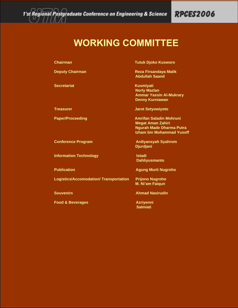
Chairman Tutuk Djoko Kusworo
Deputy Chairman Reza Firsandaya Malik Abdullah Saand
Secretariat Kusmiyati Norly Mazlan Ammar Yassin Al-Mukrary Denny Kurniawan
Treasurer Jarot Setyowiyoto
Paper/Proceeding Amrifan Saladin Mohruni Megat Aman Zahiri Ngurah Made Dharma Putra Izham bin Mohammad Yusoff
Conference Program Ardiyansyah Syahrom Djurdjani
Information Technology Istadi Dahliyusmanto
Publication Agung Murti Nugroho
Logistics/Accomodation/ Transportation Prijono Nugroho M. Ni’am Faiqun
Souvenirs Ahmad Nasirudin
Food & Beverages Azriyenni Salmiati
1st Regional Postgraduate Conference on Engineering & Science
D Advanced Material and Materials Processing Technology No. Title Authors Corresponding e-mail Corresponding
Address Page No
D1
Mode-I Interlaminar Fracture Toughness of Hand Lay-Up Plain-Weave Woven GFRP/Unsaturated Polyester Laminate
Mohd Aidy Faizal, Yeo Kiam Beng, Mohd Noh Dalimin
Center of Materials and Minerals (CMM) Universiti Malaysia Sabah, Beg Berkunci No. 2073, 88999 Kota Kinabalu, Sabah, Malaysia Tel. 088-320000 ext: 3543
287
D2 Fabrication of Polymer Light Emitting Diodes with ITO/PVK:TPP/Alq3/Al Structure
C.C. Yap, M. Yahaya and M.M. Salleh
Faculty of Science and TechnoloInstitute of Microengineering anNanoelectronics (IMEN) Universiti Kebangsaan Malaysi43600 Bangi, Selangor, MalaysTel:+60-3-89213560, Fax:+60-3-89213777,
293
D3
Identifying Meshing Characteristics To Model Crack Tip Region For Linear Fracture Mechanics Application
E.H. Lim*, K. B. Yeo, Mohamed Harimi
[email protected] or [email protected]
Centre of Materials and Minerals Universiti Malaysia Sabah, Locked Bag 2073, 88999 Kota Kinabalu, Sabah, Malaysia Tel: +6-088-320000, Ext: 3543
297
D4
Effect of Substrate Bias Voltage on The Surface Characterization of TiN coated HSS using CAPVD Technique
A. Mubarak, E. Hamzah, M. R. M. Toff
Department of Materials Engineering, Faculty of Mechanical Engineering, Universiti Teknologi Malaysia, 81310 Skudai, Johor, MALAYSIA. Tel. +60-7-5534653, Fax. +60-7-5576820,
301
D5 Strain-Induced recrystallization kinetics of Nb-high strength low alloy steel during hot rolling
E.S.Siradj [email protected]
Department Metallurgy and Materials Engineering Faculty University of Indonesia. Kampus UI Depok 16424, Tel( 021)7863510 Fax: 021 7872350
307
D6 The Properties and Kinetics of Carburized Duplex Stainless Steel
Nik Rozlin Nik Masdek, Iswadi Jauhari
Department of Mechanical Engineering, Faculty of Engineering, University of Malaya, 50603 Kuala Lumpur, Malaysia Tel: +019-3452554, Fax: +603-7967 5317
313
D7
The Pretreatments and Microwave Power Effects on Nucleation and Growth of Polycrystalline Diamond Coated Si3N4
E. Hamzah A Purniawan., M. R. M. Toff
Department of Materials Engineering, Faculty of Mechanical Engineering, Universiti Teknologi Malaysia, 81310 UTM Skudai, Johor Malaysia Telp: +60-7-5534563, Fax: +60-7-5576820
319
D8
An experimental investigation of coated ceramic cutting tools when hard turning cold work tool steel
M. A. Kamely, M. Y. Noordin, V. C. Venkatesh, D. Kurniawan
Faculty of Mechanical Engineering Universiti Teknologi Malaysia, 81310 UTM Skudai, Johor, Malaysia Tel: +60-7-5534697, Fax: +60-7-5566159,
325
D9
New Correlation between Karman Constant (�) and y-Intercept (B) for the Use of Clauser-Chart Technique to Estimate Wall Shear Stress
Sutardi [email protected]
Mechanical Engineering Department, Faculty of Industrial Technology ITS, Surabaya, Indonesia, 60111
331
vii
1st Regional Postgraduate Conference on Engineering & Science
D Advanced Material and Materials Processing Technology No. Title Authors Corresponding e-mail Corresponding
Address Page No Tel./Fac.: +62-31-5922941,
D10 Cutting Force Predictions Models in End Milling Titanium Alloy Ti-6Al-4V
A.S. Mohruni, S. Sharif, M.Y. Noordin [email protected].
Department of Mechanical Engineering, Faculty of Engineering Sriwijaya University, 30662 Indralaya, South Sumatra Indonesia Tel: +60-7-5534850, Fax: +60-7-5566159
337
D12 Additives in EDM Dielectric
Norliana Mohd Abbas, Darius G. Solomon and Md. Fuad Bahari
Faculty of Mechanical Engineering, Universiti Teknologi MARA (UiTM), Shah Alam, Selangor Darul Ehsan, Malaysia Tel: +603-5543 5159, Fax: +603-5543 5160
343
D13 The effect of moisture on the extraction rate of palm pressed fiber residue using press machine
Zainoor Hailmee Solihin, Ahmed Jaffar
Faculty of Mechanical Engineering, Universiti Teknologi MARA, 40450 Shah Alam, Selangor Darul Ehsan, MALAYSIA Tel: 6012-2646482
349
D14
A Modeling and Simulation of Process Improvement in Polyurethane Injection Manufacturing Line
Noriah Yusoff, Ahmed Jaffar [email protected]
Faculty of Mechanical Engineering University Technology MARA, 40450 Shah Alam, Selangor, Malaysia
355
D15 Taguchi Methodology-based Approach to Precision grinding of Silicon.
Alao Abdur-Rasheed, Konneh Mohamed 2
Manufacturing and Materials Engineering Department, International Islamic University Malaysia, 53100 Kuala Lumpur, Malaysia Tel: +6-0126865425, Fax: +60-3-61964568,
361
D16
Evaluation of a Material Flow Stress Model Adopted in Finite Element Modeling of Metal Cutting
M. N. Tamin, S. Izman, V. C. Venkatesh, T.T. Mon
Faculty of Mechanical Engineering, Universiti Teknologi Malaysia, 81310 UTM Skudai, Johor, Malaysia
369
D17 Microstructure and Creep Behaviour of AS-Cast Binary two phase Gamma TiAl.
E. Hamzah, 1M. Kanniah and 2M. Harun
Faculty of Mechanical Engineering, Universiti Teknologi Malaysia, 81310 Skudai, Johor Malaysia Tel: 07-5534563 Fax: 07-5566159
375
D18 Performance of wiper coated carbide tool when turning hardened stainless steel
M. Y. Noordin, D. Kurniawan, S. Sharif, Y. C. Tang
Faculty of Mechanical Engineering Universiti Teknologi Malaysia, 81310 UTM Skudai, Johor, Malaysia Tel: +60-7-5534697, Fax: +60-7-5566159
381
viii

Advanced Materials and Materials Processing Technology 337
Cutting Force Predictions Models in End Milling Titanium Alloy Ti-6Al-4V
A.S. Mohruni 1*2, S. Sharif 2, M.Y. Noordin 2
1 Department of Mechanical Engineering, Faculty of Engineering Sriwijaya University,30662 Indralaya, South Sumatra Indonesia
Tel: +60-7-5534850, Fax: +60-7-5566159, E-mail: [email protected].
2 Department of Manufacturing and Industrial Engineering Universiti Teknologi Malaysia, 81310 UTM Skudai, Johor, Malaysia
Tel: +60-7-5534850, Fax: +60-7-5566159, E-mail: [email protected]
Abstract
This paper presents a study of the development of predicted mathematical models for average tangential cutting force in end milling titanium alloy Ti-6Al-4V using uncoated solid carbide tools under flood conditions. In developing the cutting force models, the primary machining parameters such as cutting speed, feed and radial rake angle, were used as independent variables for factorial design of experiment coupled with response surface methodology (RSM). Results from the 3D-response surface contour showed that an almost constant level of cutting force was obtained during machining this advanced material. An optimum cutting conditions was also identified for a particular range of cutting force values. The models were tested by analysis of variances and were found to be adequate.
Keywords: Cutting force, End milling, Titanium Alloys, Factorial design, RSM.
1 Introduction
Titanium and its alloys are used extensively in the aerospace industry for turbine and compressor blades in the cooler parts of the engine. They are known to have excellent strength to weight ratios and corrosion resistance coupled with good elevated temperatures properties and an oxidation limit of ~ 600 oC. The α-β alloy, Ti-6Al-4V is the most common and accounts for over half of the world’s sales of titanium alloys.
Numerous studies have shown titanium and its alloys are difficult to machine, regardless of the various types of cutting tools used. This has been attributed to their low thermal conductivity, which concentrates heat in the cutting zone (typically less than 25% that of steel), retention of strength at elevated temperatures and high chemical affinity for all cutting tool materials.
Although the cutting forces generated are not excessively high (almost similar to those with steel), they are confined to a small area due to the short chip contact length which leads to high stresses. The combination of high stress and temperature resulted in plastic deformation of the tool edge. Depth of cut notching and chipping at the flank can also be a problem with intermittent cutting operations. [1]
End milling is one of the most widely used machining operation and the aerospace industry places heavy demand on this process due to both the shape and complexity of the parts and the dimensional accuracy required. Recent * Corresponding Author. E-mail: [email protected], Tel: +60-7-5534770, Fax: +60-7-5566159
approaches to the problem of designing a suitable data selection system for Computer Integrated Manufacturing (CIM) application are to use machinability database systems in the form of mathematical model which have considerable advantages over simple data retrieval systems [2]. For this purpose, an approach to develop a mathematical model for the average tangential cutting force in end milling Ti-6Al-4V by factorial design of experiment coupled with RSM was conducted.
2 Cutting Forces in End Milling
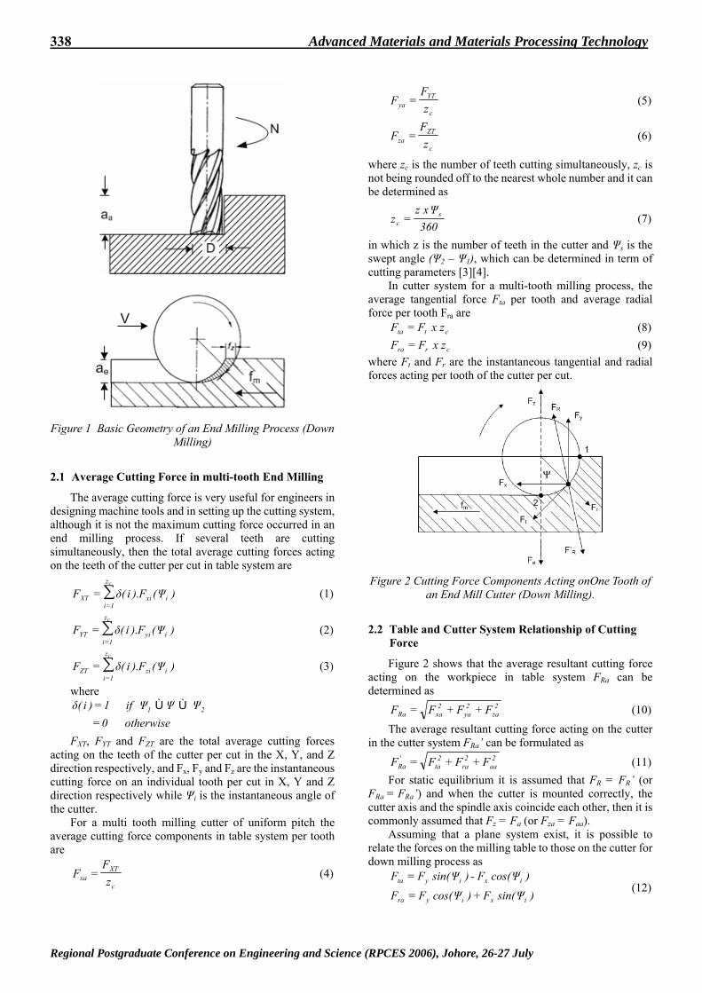
The basic geometry of the end milling process for down milling is presented in Figure 1. The cutting force components acting on one tooth of the end mill cutter are shown in Figure 2. There are two cutting force components system. The first is the table system (Fx, Fy, Fz, FR), its indices illustrated the direction of the cutting force in x-y-z coordinate respectively and the resultant force. The second is known as the cutter system of cutting forces which consists of four components Ft, Fr, Fa and FR’, they are tangential, radial, axial and projection of the resultant force respectively [3][4].
Regional Postgraduate Conference on Engineering and Science (RPCES 2006), Johore, 26-27 July
338 Advanced Materials and Materials Processing Technology
Figure 1 Basic Geometry of an End Milling Process (Down
Milling)
2.1 Average Cutting Force in multi-tooth End Milling
The average cutting force is very useful for engineers in designing machine tools and in setting up the cutting system, although it is not the maximum cutting force occurred in an end milling process. If several teeth are cutting simultaneously, then the total average cutting forces acting on the teeth of the cutter per cut in table system are
∑=
=cz
1iixiXT )(F).i(F Ψδ (1)
∑=
=cz
1iiyiYT )(F).i(F Ψδ (2)
∑=
=cz
1iiziZT )(F).i(F Ψδ (3)
where
otherwise 0 if 1)i( 21
=≤≤= ΨΨΨδ
FXT, FYT and FZT are the total average cutting forces acting on the teeth of the cutter per cut in the X, Y, and Z direction respectively, and Fx, Fy and Fz are the instantaneous cutting force on an individual tooth per cut in X, Y and Z direction respectively while Ψi is the instantaneous angle of the cutter.
For a multi tooth milling cutter of uniform pitch the average cutting force components in table system per tooth are
c
XTxa z
FF = (4)
c
YTya z
FF = (5)
c
ZTza z
FF = (6)
where zc is the number of teeth cutting simultaneously, zc is not being rounded off to the nearest whole number and it can be determined as
360 x z
z sc
Ψ= (7)
in which z is the number of teeth in the cutter and Ψs is the swept angle (Ψ2 – Ψ1), which can be determined in term of cutting parameters [3][4].
In cutter system for a multi-tooth milling process, the average tangential force Fta per tooth and average radial force per tooth Fra are
ctta z x FF = (8)
crra z x FF = (9) where Ft and Fr are the instantaneous tangential and radial forces acting per tooth of the cutter per cut.
Figure 2 Cutting Force Components Acting onOne Tooth of
an End Mill Cutter (Down Milling).
2.2 Table and Cutter System Relationship of Cutting Force
Figure 2 shows that the average resultant cutting force acting on the workpiece in table system FRa can be determined as
2za
2ya
2xaRa FFFF ++= (10)
The average resultant cutting force acting on the cutter in the cutter system FRa’ can be formulated as
2aa
2ra
2ta
'Ra FFFF ++= (11)
For static equilibrium it is assumed that FR = FR’ (or FRa = FRa’) and when the cutter is mounted correctly, the cutter axis and the spindle axis coincide each other, then it is commonly assumed that Fz = Fa (or Fza = Faa).
Assuming that a plane system exist, it is possible to relate the forces on the milling table to those on the cutter for down milling process as
)sin(F)cos(FF
)cos(F - )sin(FF
ixiyra
ixiyta
ΨΨ
ΨΨ
+=
= (12)
Regional Postgraduate Conference on Engineering and Science (RPCES 2006), Johore, 26-27 July
Advanced Materials and Materials Processing Technology 339
3 Development the Mathematical Model for Cutting Forces
In machinability study investigations, statistical design of experiment is used quite extensively. Statistical design of experiment refers to the process of planning the experiment so that the appropriate data can be analyzed by statistical methods, resulting in valid and objective conclusions. Design and method such as factorial design of experiment and RSM are nowadays widely used to replace one-factor-at-a-time experimental approach which is time and cost consuming.[5]
For this purpose, the mathematical model relating to the machining response and their factor were developed to facilitate the optimization of the machining process. They have been developed stepwise using 3F1-factorial design and RSM using experimental results.
3.1 Postulation of the Mathematical Models
It is assumed that the proposed model for the cutting force is merely a function of cutting speed V, feed fz and radial rake angle γ. Other factors such as machine tools stability, entry and exit condition etc are kept constant. Thus the proposed models for cutting force in end milling Ti-6Al-4V can be expressed as
'fCVF mlz
kta εγ= (13)
where Fta is the calculated average tangential cutting force (N), fz is the feed per tooth (mm.tooth-1), γ is the radial rake angle (o), ε’ is the experimental error and C, k, l, m are parameters to be estimated using experimental data.
By performing a natural logarithmic transformation equation 13 can be converted into first order polynomial as
'lnlnmflnlVlnkClnFln zta εγ ++++= (14)
which can also be formed as ε++++= 33221100 xbxbxbxby (15)
and finally can be written as
332211001 xbxbxbxb - yy +++== ε (16)
where y is the calculated average tangential force on a natural logarithmic scale, ŷ1 is the natural logarithmic value of predictive (estimated) tangential cutting force, x0 = 1 (a dummy variable), x1, x2 and x3 are the coded variables of V, fz, and γ respectively, ε = ln ε’ and b0, b1, b2 and b3 are the model parameters to be estimated using the experimental data. [6]
In extended observation region, the second-order model is also useful when the second order effect of V, fz, γ and the two way interactions amongst V, fz, and γ are significant. The second order can be extended from the first-order model in equation 16 as
2333
2222
2111
322331132112
33221100
2
xbxbxb
xxbxxbxxb xbxbxbxb
- yy
+++
++++++=
= ε
(17)
where the b values are the parameters, which are to be estimated by method of least squares and ŷ2 is the estimated
response on logarithmic scale. Validity of the models used for optimizing the process
parameters has to be tested using ANOVA.
3.2 Experimental Works
Before commencing the experimental trials, thorough planning was essential in order to obtain the relevant data in developing the mathematical models. By taking into consideration the factors for experimentation and analysis such as cutting speed, feed and radial rake angle, the design of experiments (DOE) were used stepwise from 23-factorial design to central composite design (CCD), which is easily gained by augmentation 23-design with replicated star points. 3.2.1 Experimental Design
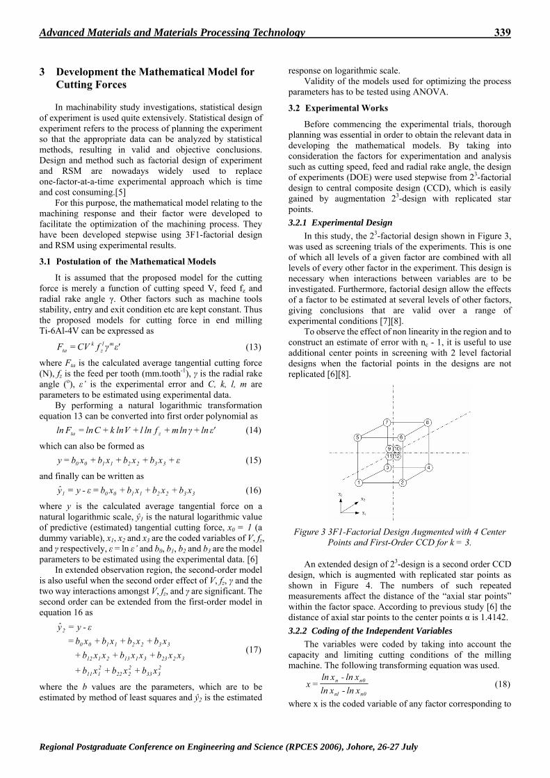
In this study, the 23-factorial design shown in Figure 3, was used as screening trials of the experiments. This is one of which all levels of a given factor are combined with all levels of every other factor in the experiment. This design is necessary when interactions between variables are to be investigated. Furthermore, factorial design allow the effects of a factor to be estimated at several levels of other factors, giving conclusions that are valid over a range of experimental conditions [7][8].
To observe the effect of non linearity in the region and to construct an estimate of error with nc - 1, it is useful to use additional center points in screening with 2 level factorial designs when the factorial points in the designs are not replicated [6][8].
Figure 3 3F1-Factorial Design Augmented with 4 Center
Points and First-Order CCD for k = 3.
An extended design of 23-design is a second order CCD design, which is augmented with replicated star points as shown in Figure 4. The numbers of such repeated measurements affect the distance of the “axial star points” within the factor space. According to previous study [6] the distance of axial star points to the center points α is 1.4142. 3.2.2 Coding of the Independent Variables
The variables were coded by taking into account the capacity and limiting cutting conditions of the milling machine. The following transforming equation was used.
0nnl
0nn
xln - xlnxln - xln
x = (18)
where x is the coded variable of any factor corresponding to
Regional Postgraduate Conference on Engineering and Science (RPCES 2006), Johore, 26-27 July
340 Advanced Materials and Materials Processing Technology
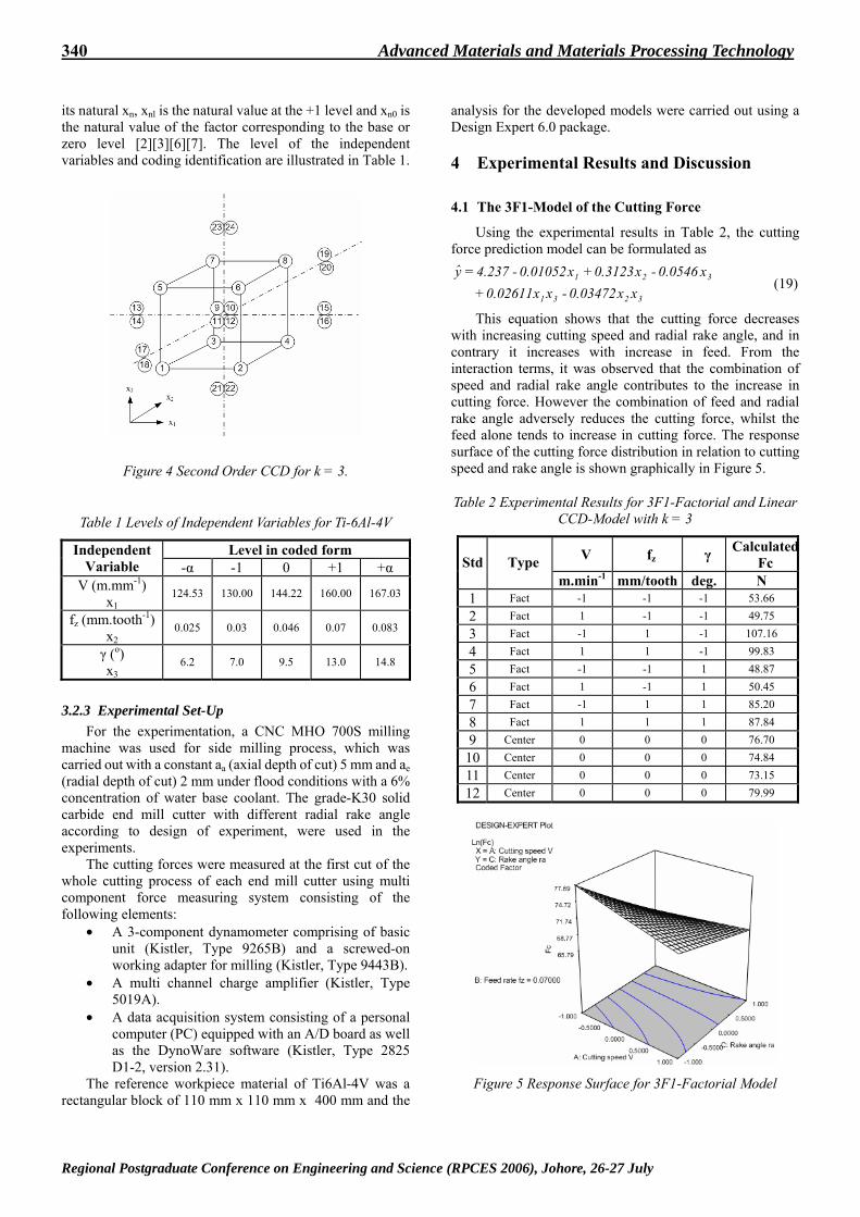
its natural xn, xnl is the natural value at the +1 level and xn0 is the natural value of the factor corresponding to the base or zero level [2][3][6][7]. The level of the independent variables and coding identification are illustrated in Table 1.
Figure 4 Second Order CCD for k = 3.
Table 1 Levels of Independent Variables for Ti-6Al-4V
Level in coded form Independent Variable -α -1 0 +1 +α
V (m.mm-1) x1
124.53 130.00 144.22 160.00 167.03
fz (mm.tooth-1) x2
0.025 0.03 0.046 0.07 0.083
γ (o) x3
6.2 7.0 9.5 13.0 14.8
3.2.3 Experimental Set-Up
For the experimentation, a CNC MHO 700S milling machine was used for side milling process, which was carried out with a constant aa (axial depth of cut) 5 mm and ae (radial depth of cut) 2 mm under flood conditions with a 6% concentration of water base coolant. The grade-K30 solid carbide end mill cutter with different radial rake angle according to design of experiment, were used in the experiments.
The cutting forces were measured at the first cut of the whole cutting process of each end mill cutter using multi component force measuring system consisting of the following elements:
• A 3-component dynamometer comprising of basic unit (Kistler, Type 9265B) and a screwed-on working adapter for milling (Kistler, Type 9443B).
• A multi channel charge amplifier (Kistler, Type 5019A).
• A data acquisition system consisting of a personal computer (PC) equipped with an A/D board as well as the DynoWare software (Kistler, Type 2825 D1-2, version 2.31).
The reference workpiece material of Ti6Al-4V was a rectangular block of 110 mm x 110 mm x 400 mm and the
analysis for the developed models were carried out using a Design Expert 6.0 package.
4 Experimental Results and Discussion
4.1 The 3F1-Model of the Cutting Force
Using the experimental results in Table 2, the cutting force prediction model can be formulated as
3231
321
xx03472.0 - xx02611.0 x0546.0 - x3123.0x01052.0 - 237.4y
++=
(19)
This equation shows that the cutting force decreases with increasing cutting speed and radial rake angle, and in contrary it increases with increase in feed. From the interaction terms, it was observed that the combination of speed and radial rake angle contributes to the increase in cutting force. However the combination of feed and radial rake angle adversely reduces the cutting force, whilst the feed alone tends to increase in cutting force. The response surface of the cutting force distribution in relation to cutting speed and rake angle is shown graphically in Figure 5.
Table 2 Experimental Results for 3F1-Factorial and Linear CCD-Model with k = 3
V fz γ CalculatedFc Std Type
m.min-1 mm/tooth deg. N 1 Fact -1 -1 -1 53.66 2 Fact 1 -1 -1 49.75 3 Fact -1 1 -1 107.16 4 Fact 1 1 -1 99.83 5 Fact -1 -1 1 48.87 6 Fact 1 -1 1 50.45 7 Fact -1 1 1 85.20 8 Fact 1 1 1 87.84 9 Center 0 0 0 76.70
10 Center 0 0 0 74.84 11 Center 0 0 0 73.15 12 Center 0 0 0 79.99
Figure 5 Response Surface for 3F1-Factorial Model
Regional Postgraduate Conference on Engineering and Science (RPCES 2006), Johore, 26-27 July
Advanced Materials and Materials Processing Technology 341
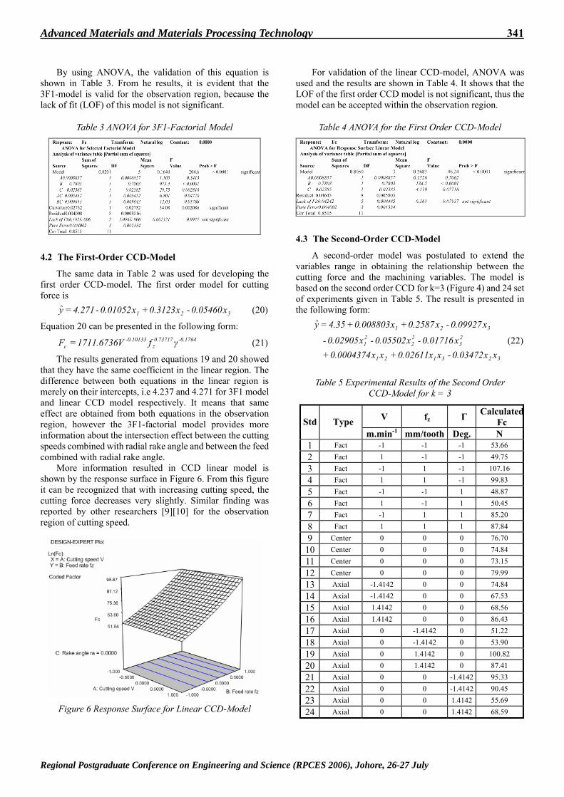
By using ANOVA, the validation of this equation is shown in Table 3. From he results, it is evident that the 3F1-model is valid for the observation region, because the lack of fit (LOF) of this model is not significant.
Table 3 ANOVA for 3F1-Factorial Model
4.2 The First-Order CCD-Model
The same data in Table 2 was used for developing the first order CCD-model. The first order model for cutting force is
321 x05460.0 - x3123.0x01052.0 - 271.4y += (20)
Equation 20 can be presented in the following form: 1764.0-73717.0
z10133.0-
c fV6736.1711F γ= (21)
The results generated from equations 19 and 20 showed that they have the same coefficient in the linear region. The difference between both equations in the linear region is merely on their intercepts, i.e 4.237 and 4.271 for 3F1 model and linear CCD model respectively. It means that same effect are obtained from both equations in the observation region, however the 3F1-factorial model provides more information about the intersection effect between the cutting speeds combined with radial rake angle and between the feed combined with radial rake angle.
More information resulted in CCD linear model is shown by the response surface in Figure 6. From this figure it can be recognized that with increasing cutting speed, the cutting force decreases very slightly. Similar finding was reported by other researchers [9][10] for the observation region of cutting speed.
Figure 6 Response Surface for Linear CCD-Model
For validation of the linear CCD-model, ANOVA was used and the results are shown in Table 4. It shows that the LOF of the first order CCD model is not significant, thus the model can be accepted within the observation region.
Table 4 ANOVA for the First Order CCD-Model
4.3 The Second-Order CCD-Model
A second-order model was postulated to extend the variables range in obtaining the relationship between the cutting force and the machining variables. The model is based on the second order CCD for k=3 (Figure 4) and 24 set of experiments given in Table 5. The result is presented in the following form:
323121
23
22
21
321
xx03472.0 - xx02611.0xx0004374.0 x0.01716 - x0.05502 - x02905.0 -
x09927.0 - x2587.0x008803.035.4y
++
++=
(22)
Table 5 Experimental Results of the Second Order CCD-Model for k = 3
V fz Γ CalculatedFc Std Type
m.min-1 mm/tooth Deg. N 1 Fact -1 -1 -1 53.66 2 Fact 1 -1 -1 49.75 3 Fact -1 1 -1 107.16 4 Fact 1 1 -1 99.83 5 Fact -1 -1 1 48.87 6 Fact 1 -1 1 50.45 7 Fact -1 1 1 85.20 8 Fact 1 1 1 87.84 9 Center 0 0 0 76.70
10 Center 0 0 0 74.84 11 Center 0 0 0 73.15 12 Center 0 0 0 79.99 13 Axial -1.4142 0 0 74.84 14 Axial -1.4142 0 0 67.53 15 Axial 1.4142 0 0 68.56 16 Axial 1.4142 0 0 86.43 17 Axial 0 -1.4142 0 51.22 18 Axial 0 -1.4142 0 53.90 19 Axial 0 1.4142 0 100.82 20 Axial 0 1.4142 0 87.41 21 Axial 0 0 -1.4142 95.33 22 Axial 0 0 -1.4142 90.45 23 Axial 0 0 1.4142 55.69 24 Axial 0 0 1.4142 68.59
Regional Postgraduate Conference on Engineering and Science (RPCES 2006), Johore, 26-27 July

342 Advanced Materials and Materials Processing Technology
It was interesting to observe that when the region was extended, the contour of cutting force in the cutting speed range changes from linear (Figure 6) to a slightly curve form (Figure 7). This was also confirmed by other researchers [9][10] for low and high cutting speeds region. They found that the cutting force was very high at low cutting speed and reduced rapidly at medium cutting speed and finally increased slightly with further increase in cutting speed. It was also observed in Figure 7 that there was a significant increase in cutting force with increase in feed.
Figure 7 Response Surface for the Second Order
CCD-Model
From ANOVA results, it was also found that the second order CCD model can be used as the mathematical model in the region of observation, since the LOF of this model is not significant as shown in Table 6.
Table 6 ANOVA for the Second Order CCD-Model
5 Conclusions
• There are three appropriate prediction models namely 3F1-, linear CCD and second order CCD model to formulate the relationship amongst the machining parameters such as cutting speed (130-160 m/min), feed (0.03-0.07 mm/tooth), radial rake angle (7-13 o).
• With increasing cutting speed, the cutting force decreases slightly in the region of observation.
• Feed is the most significant factor that influences the cutting force. It increases significantly with increasing feed in the observation region.
• Increasing the radial rake angle gradually reduced the cutting force.
Acknowledgements
The authors wish to thank the research Management Center, UTM and the Ministry of Science, Technology and Innovation Malaysia for their financial support to the above project through the IRPA funding 03-02-02-0068 PR0074/03-01 – Vote no. 74545.
References
[1]. Niemann, H.; Eu-gene Ng.; Loftus, H.; Sharman, A.; Dewes, R. and Aspinwall, D. 2002, The Effect of Cutting Environment and Tool Coating when High Speed Ball Nose End Milling titanium Alloy, In Metal Cutting and High Speed Machining, edited by Dudzinski, D.; Molinari, A.; Schulz, H., Kluwer Academic/Plenum Publisher.
[2]. Alauddin, M.; El Baradie, M.A.; Hashmi, M.S.J. 1996, Modelling of Cutting Force in End Milling Inconel 718, Journal of Material Processing Technology 58: 100-108.
[3]. Alauddin, M. 1993, End Milling Machinability of Steel, a Nickel-base Alloy (Inconel 718) and a Metal Matrix Composite. PhD Thesis, Dublin City University.
[4]. Paucksch, E. 11th eds. 1996, Zerspantechnik, Viewegs- Fachbuecher der Technik, Braunschweig.
[5]. Noordin, M.Y.; Venkatesh, V.C.; Sharif, S.; Elting, S.; Abdullah, A. 2004, Application of Response Surface Methodology in Describing the Performance of Coated Carbide Tools when Turning AISI 1045 Steel, Journal of Materials Processing Technology 145: 46–58.
[6]. Sharif, S.; Mohruni, A.S.; Noordin, M.Y. 2006, Modeling of Tool life when End Milling on Titanium Alloy (Ti-6Al-4V) using Response Surface Methodology, In Proceeding of the 1st International Conference & 7th AUN/SEED-Net Fieldwise Seminar on Manufacturing and Material Processing, 14-15 March: 127-132.
[7]. Choudhury, I.A.; El-Baradie, M.A. 1999, Machinability assessment of Inconel 718 by Factorial Design of Experiment Coupled with Response Surface Methodology, Journal of Materials Processing Technology, 95: 30-39.
[8]. Meyrs, R.H.; Montgomery, D.C. 2nd eds. 2002, Response Surface Methodology: Process and Product Optimization using Designed Experiments, John Wiley & Sons, Inc.
[9]. Trent, E.M.; Wright, P.K. 4th eds. 2000, Metal Cutting, Butterworth-Heinemann
[10]. Xu, J.H.; Ren, K.Q.; Geng, G.S. 2004, Cutting Forces in High Speed Milling of a Close Alpha Titanium Alloy, In Key Engineering Materials Vols. 259-260: 451-455.
Regional Postgraduate Conference on Engineering and Science (RPCES 2006), Johore, 26-27 July