nursy afikah binti f arakkasi this report is submitted in...
TRANSCRIPT

CHARACTERIZATION OF 5G ANTENNA AT 38 GHz
NURSY AFIKAH BINTI F ARAKKASI
This Report is submitted in Partial Fulfilment of Requirement for Award of
Bachelor of Electronic Engineering (Electronic Telecommunication) With Honours
Faculty of Electronics and Computer Engineering
Universiti Teknikal Malaysia Melaka
JUNE 2016

Tajuk Projek
Sesi Pengajian 1
UNIVERSTI TEKNIKAL MALAYSIA MELAKA FAKULTI KEJURUTERAAN ELEKTRONIK DAN KEJURUTERAAN KOMPUTER
5
BORANG PENGESAHAN STATUS LAPORAN
PROJEK SARJANA MUDA II
I 1 6
(HURUF BESAR)
mengaku membenarkan L aporan Projek Sarjana Muda ini disimpan di Perpustakaan dengan syarat- syarat kegunaan seperti berikut:
1. Laporan adalah hakmilik Universiti Teknikal Malaysia Melaka.
2. Perpustakaan dibenarkan membuat salinan untuk tujuan pengajian sahaja . 3. Perpustakaan dibenarkan membuat salinan laporan ini sebagai bahan pertukaran antara institusi
pengajian tinggi . 4. Sila tandakan ( 1/ ) :
D SULIT*
D TERHAD**
D TIDAK TERHAD
7 {TANDATANGAN PENULIS)
Tarikh: 15 Jun 2016
* (Mengandungi maklumat yang berdarjah keselamatan atau kepentingan Malaysia seperti yangtermaktub di dalam AKTA
RAHSIA RASMI1972)
* * (Mengandungi maklumat terhad yang telah ditentukan oleh
organisasi/badan di mana penyelidikan dijalankan)
Disahkan oleh :
/ {COP DAN TANDATANGAN PENYELIA)
.... I..,. Bln llohd Ibrahim s.rtior L~Uffl'f
fMIIitr Eilc:lrDnic: end Computer Engineenng (FKEtv, , 1Jn1YW1111i Te&nikal Walaysla Melaka (UTeM )
H4lnCI Tuah Jaye 71110 DuRell T~ ......
Tarikh : 15 Jun 2016

"I hereby declare that the work in this project is my own except for summaries and
quotations which have been duly acknowledging."
Signature : .. .... ... .. ... / .............. .
Author : NURSY AFIKAH BINTI F ARAKKASI
Date : 15THJUNE2Ql6
iii

iv
"I acknowledge that I have read this report and in my opinion, this report is sufficient
in term of scope and quality for the award of Bachelor of Electronic Engineering
(Electronic Telecommunication) with Honours ."
Signature : .. ~- . . .. ..... . ... . . ... . . .
Supervisor' s Name :DR IMRAN BIN MOHD IBRAHIM
Date : 15TH JUNE 2016

v
DEDICATION
Special dedication to my lovely parents, Farakkasi bin Labundu and Isawami binti
Lateddu, my siblings, my kind hearted supervisor Dr. Imran bin Mohd Ibrahim, all
lectures in Faculty of Electronic and Computer Engineering and to my dearest friend.
vi
ACKNOWLEDGEMENT
Alhamdulillah, all Praise to thank Allah SWT the Almighty for giving me the
Rahmah to finish my Project Sarjana Muda. Thanks to Allah because I manage to
complete my final year project without a major hiccup. I am indebted to my supervisor,
Dr. Imran Mohamad Ibrahim of his priceless effort in assisting me whenever I find
difficulties in completing my task and for reviewing my report and comments for
improving this report. I specially thank to my family, especially my lovely parents,
Farakkasi Labundu and Isawami Lattedu for the continuous support throughout my
day and to my friends for their time, concern, efforts and always encouraging me when
preparing this report. A word of thanks to everybody that involve in my project directly
or indirectly. Not forget to Universiti Teknikal Malaysia Melaka (UTeM) for the
opportunity given. I pray to Allah SWT may He bless all of you.

vii
ABSTRACT
Nowadays, the antenna is very important in wireless communication system. This
project is designing microstrip antenna array by using millimetre wave technology.
Microstrip patch antenna have a low profile, simple and low cost. This type of antenna
can be used in many application such as satellite, radar, and wireless communication.
The purpose of this project to design high gain antenna used for the 50 application.
This project started analyses the single patch antenna then follow by 2x2, 4x4, and 8x8
antenna array. The design of 2x2, 4x4, and 8X8 microstrip array antenna at 38 GHz
using transmission line model and coaxial feed. The antenna simulated using CST
software. The length of the gap and substrate thickness are adjusted to meet desired
frequency. The gain and beam width of 8x8 microstrip array is 22.7 dBi and 8 degrees
respectively.
viii
ABSTRAK
Sejak kebelakangan ini, antenna memainkan peranan penting dalam komunikasi tanpa
wayar. Projek ini direkabentuk dengan mengunakan teknologi gelombang milimeter.
Mikrojalur antenna mempunyai ciri-ciri seperti kos rendah, mudah dan 'low profile'.
Antenna j en is ini ban yak di gunakan dalam aplikasi satelit, radar dan komunikasi tanpa
wayar. Tujuan projek ini adalah untuk menghasilkan antenna gandaan yang tinggi
untuk di gunakan pada aplikasi 5G. Projek ini bermula dengan menganalisis satu
antena mikrojalur di ikuti dengan 2x2, 4x4 dan 8x8 antena mikrojalur. Rekabentuk
2x2, 4x4 dan 8x8 antena pada frekuensi 38 GHz menggunakan transmisi model dan
teknik coaxial. Simulasi antenna ini adalah menggunakan perisian CST. Panjang 'gap '
antenna dan ketebalan substrat boleh mengawal frekuensi yang ditetapkan. gandaan
dan alur lebar antenna mikrojalur 8x8 adalah masing-masing 22.7 dBi dan 8°.

ix
TABLE OF CONTENT
CHAPTER TITLE PAGE
PROJECT TITLE
PSM STATUS VERIFICATION ii
STUDENT DECLARATION iii
SUPERVISOR DECLARATION iv
DEDICATION v
ACKNOWLEDGEMENT vi
ABSTRACT vii
ABSTRAK viii
TABLE OF CONTENT ix
LIST OF TABLES xiv
LIST OF FIGURES XV
LIST OF ABBREVIATION xviii
LIST OF APPENDICES XX
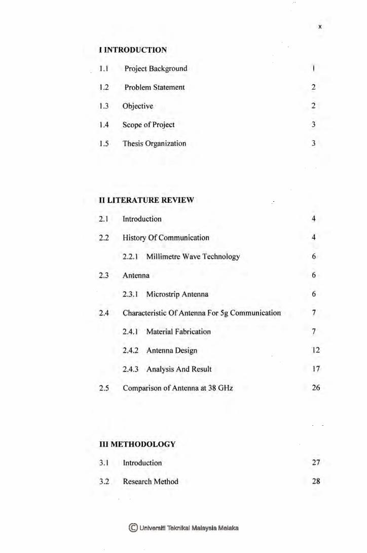
I INTRODUCTION
1.1 Project Background
1.2 Problem Statement
1.3 Objective
1.4 Scope of Project
1.5 Thesis Organization
II LITERATURE REVIEW
2.1 Introduction
2.2 History Of Communication
2.2.1 Millimetre Wave Technology
2.3 Antenna
2.3.1 Microstrip Antenna
2.4 Characteristic Of Antenna For 5g Communication
2.4.1 Material Fabrication
2.4.2 Antenna Design
2.4.3 Analysis And Result
2.5 Comparison of Antenna at 38 GHz
III METHODOLOGY
3.1
3.2
Introduction
Research Method
X
2
2
3
3
4
4
6
6
6
7
7
12
17
26
27
28

xi
3.2.1 Project Methodology 29
3.3 Antenna Design 30
3.3.1 Design Specification 30
3.3.1.1 Type Of Substrate 31
3.3.1.2 Feed Technique 31
3.3.1.3 Method Of Analysis 31
3.3.1.4 Design Parameter 32
3.3.2 Calculation of Microstrip Antenna 34
3.3.3 The Antenna Array 34
3.4 Simulation 38
IV RESULT AND DISCUSSION
4.1 Introduction 46
4.2 Results 46
4.2.1 Simulation Single Microstrip Antenna 47
4.2.1 .1 Return Loss 47
. 4.2.1.2 Gain 48
4.2.1.3 Radiation Pattern 50
4.2.2 Simulation of 2x2 Antenna Array 51
4.2.2.1 Return Loss 52
4.2.2.2 Gain 53
4.2.2.3 Radiation Pattern 54
4.2.3 Simulation of 4x4 Antenna Array 55

4.2.3.1 Return Loss
4.2.3 .2 Gain
4.2.3.3 Radiation Pattern
4.2.4 Simulation of 8x8 Antenna Array
4.2.4.1 Return Loss
4.2.4.2 Gain
4.2.4.3 Radiation Pattern
4.3 Discussion
4.2.1 Comparison S 11 Parameter
4.3.2 Comparison Gain Parameter
4.3.3 Comparison of Radiation Pattern
4.3.4 Comparison of Efficiency
4.3.5 Comparison of Bandwidth
4.3.6 Effect of Thickness Substrate On 8x8
Antenna Array
V CONCLUSION AND FUTURE WORK
5.1
5.2
5.3
Introduction
Conclusion
Future Work
REFERENCES
xii
55
56
57
59
59
60
62
63
63
65
66
67
68
69
70
70
72
73

xiii
APPENDIX 76
xiv
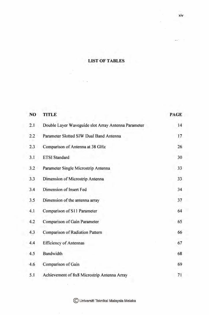
LIST OF TABLES
NO TITLE PAGE
2.1 Double Layer Waveguide slot Array Antenna Parameter 14
2.2 Parameter Slotted SIW Dual Band Antenna 17
2.3 Comparison of Antenna at 38 GHz 26
3.1 ETSI Standard 30
3.2 Parameter Single Microstrip Antenna 33
3.3 Dimension of Microstrip Antenna 33
3.4 Dimension of Insert Fed 34
3.5 Dimension of the antenna array 37
4.1 Comparison of S 11 Parameter 64
4.2 Comparison of Gain Parameter 65
4.3 Comparison ofRadiation Pattern 66
4.4 Efficiency of Antennas 67
4.5 Bandwidth 68
4.6 Comparison of Gain 69
5.1 Achievement of 8x8 Microstrip Antenna Array 71

XV
LIST OF FIGURES
NO TITLE PAGE
2.1 History of communication 5
2.2 Microstrip patch antenna 7
2.3 Lithium Niobate 8
2.4 Antenna Coupled Modulator 9
2.5 Plate Copper 9
2.6 Antenna with Shielding Wall 10
2.7 Dual band array antenna 11
2.8 Material of SIW II
2.9 Printed Yagi Uda Antenna 12
2.10 Printed Yagi Uda Antenna 13
2.11 Double Layer Waveguide slot Array Antenna 14
2.12 : H Shape slot Antenna 15
2.13 Slotted SIW Dual Band Antenna 16
2.14 1 x4 Slotted SIW Dual Band Antenna 16
2.15 Analysis 1 18
xvi
2.16 Analysis 2 19
2.17 NoQPM 19
2.18 With QPM 20
2.19 Conversion Efficiency on Fabricated Device 20
2.20 Analysis 3 21
2.21 Return Loss and Gain 22
2.22 Analysis 4 22
2.23 Analysis 5 23
2.24 Return Loss 24
2.25 Radiation Pattern 24
2.26 Return Loss 25
2.27 Radiation Pattern 25
3.1 Project Methodology 29
3.2 Transmission Line 32
3.3 : Single Patch Antenna 32
3.4 Feed Network 36
3.5 Quarter Wavelength 37
3.6 Workflow 38
3.7 Time Domain 39
3.8 Unit 40
3.9 Setting 41
3.10 Modelling 42
3.11 Transform 43
3.12 Boolean 43

xvii
3.13 Waveguide Port 44
3.14 Time Domain solver Parameter 45
4.1 Microstrip Patch Antenna at 38 GHz 47
4.2 Return Loss of Single Microstrip Antenna 48
4.3 Gain in 3D 49
4.4 Gain in 20 49
4.5 Radiation pattern for Single Microstrip Antenna 50
4.6 2X2 Microstrip Array Antenna 51
4.7 Return Loss for 2x2 Microstrip Array Antenna 52
4.8 Gain of2x2 Microstrip Array Antenna 53
4.9 Linear power pattern of2x2 Microstrip Array Antenna 54
4.10 4x4 Microstrip Array Antenna 55
4.11 Return Loss of 4x4 Microstrip Array Antenna 56
4.12 Gain of 4x4 Microstrip Array Antenna 57
4.13 Radiation Pattern of 4x4 Microstrip Array Antenna 58
4.14 8x8 Microstrip Array Antenna 59
4.15 Return Loss 8x8 Microstrip Antenna Array 60
4.16 Gain of 8x8 Microstrip Antenna Array 61
4.17 Radiation Pattern 8x8 Microstrip Antenna Array 62
4.18 Comparison ofFrequency 63
4.19 Antenna Gain in 3D 65
lG
2G
3G
4G
5G
CST
CPW
EO
ETSI
FNBW
HPBW
LTE
METIS
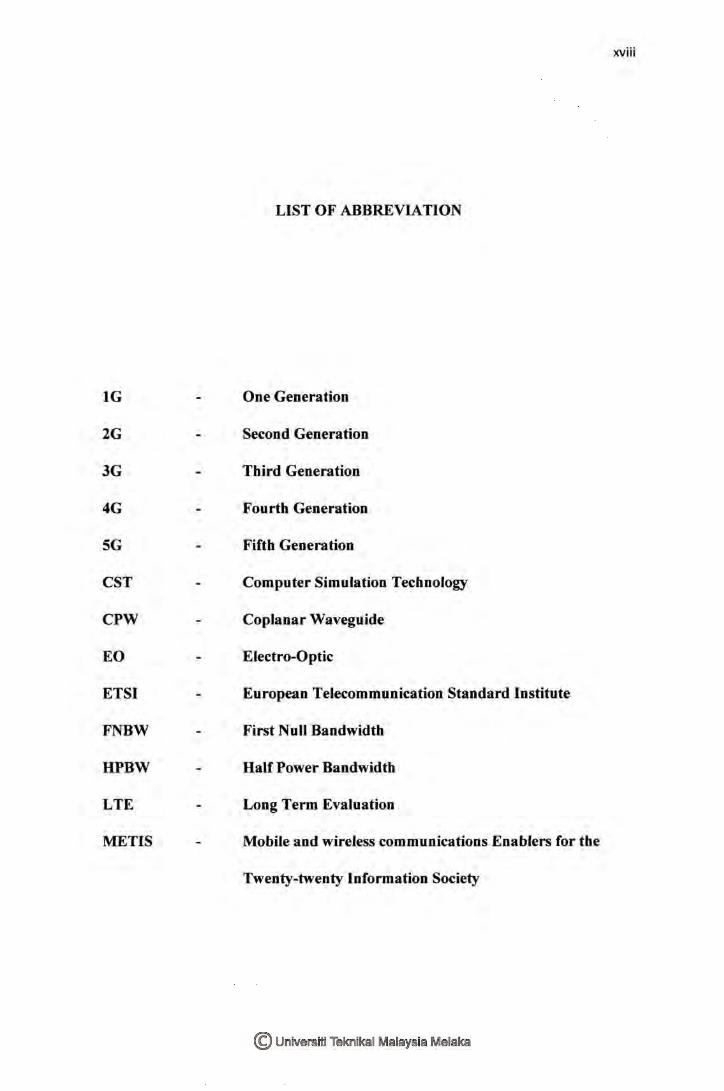
LIST OF ABBREVIATION
One Generation
Second Generation
Third Generation
Fourth Generation
Fifth Generation
Computer Simulation Technology
Coplanar Waveguide
Electro-Optic
European Telecommunication Standard Institute
First Null Bandwidth
Half Power Bandwidth
Long Term Evaluation
Mobile and wireless communications Enablers for the
Twenty-twenty Information Society
xviii

QPM
SIW
Quasi-Phase Matching
Substrate Integral Waveguide
xix

LIST OF APPENDICES
NO TITLE
A Inotek Poster
B RT Duroid Data Sheet
XX
PAGE
76
77
1
CHAPTER I
INTRODUCTION
1.1 Project Background
Communication technology has grown to become a part of our lives. This
technology has changes our lives dramatically from 1 G to 4G communication. Now
we are trying to come out with 5G communication to enhance the previous
communication technology. 5G communication will be commercialized in 2020 and it
has the ability to send Giga Byte data per second and faster than 4G communication.
For the future communication technology, people can use a smartphone to work
anywhere and anytime. In this project, we are focusing on basic antenna theory to
understand how it operates.
A lot of research in order to produce 5G communication. METIS is one of the
biggest projects with objective toward 5G building and system [1] funded by European
Commission which is a start in November 2012. This study focusing of millimetre
waves antenna system. This system operates at high frequency.
2
To make our imagination become reality, we are trying to design an antenna
for 5G communication at 38 GHz. This project using Computer Simulation
Technology (CST), it will analysis the important part of the antenna such as return
loss, radiation pattern and so on. By designing an antenna 5G communication, we can
analyse the performance characteristic of antenna 5G communication at 38 GHz.
1.2 Problem Statement
Communication technology is the most vital technology. Today the world is
facing 4G communication in many countries which is provided a lot of advantages to
the user, for example, the LTE service. However, the user' s demand on the high data
rate, high speed, and low latency. This technology required larger bandwidth, high
gain, narrow beam and high-efficiency Hence to fulfill the 5G technology, future
antenna 5G is needed. The frequency of 38 GHz was been choose to increase the
capacity as well as to increase the antenna gain which is larger than 20 dBi. The
microstrip antenna is used due to the low cost, simple, and easy to fabricate. Therefore,
by designing microstrip antenna array it will help to solve this problem.
1.3 Objective
The objective of the project is to design the Microstrip Antenna Array with
high gain (>20 dBi) for 5G application at 38 GHz.
3
1.4 Scope of Project
To design microstrip antenna array for 5G application at 38 GHz, the studies
are based on basic microstrip antenna and millimeter wave technology. The project
developing using Computer Simulation Technology (CST). This project includes
calculation, design, and simulation to get the specification of 5G antenna. This design
refers to European Telecommunication Standard Institute. Finally, design and analyse
microstrip antenna array to get high gain (>20 dBi).
1.5 Thesis Organization
This study consists of five chapter. Chapter one talk about the introduction of
the antenna at 38 GHz for 5G communication. This concern leads to study on
fundamental of the antenna in order to design it. Next, chapter two basically focus on
previous study or literature review on designing 5G antenna. Chapter three discuss
methodology. This chapter includes simulation of 5G antenna at 38 GHz. After that,
chapter four focused on result and discussion from simulation and compare them.
Conclusion for this project and future developments were briefly on chapter five.
4
CHAPTER II
LITERATURE REVIEW
2.1 Introduction
A literature review is a text of a scholarly paper, which includes the current
knowledge, including substantive findings, as well as theoretical and methodological
contributions to this project. This chapter reviews of articles, books and journals to
understand the concept that needs to know in order to complete this project.
2.2 History of Communication
The brick phone was launched in 1973. It is the first generation (1 G) phone,
the start of personal mobile communication which is in the analog signal. Second
generation (2G) communication debuted in 1991. 2G is a digital signal that allowed
the user to transmit data like a text message. In 2001 , the third generation (3G) start to