managing voltage fluctuation issues in distribution system
TRANSCRIPT
Jurnal Kejuruteraan SI 2(1) 2019: 27-33https://doi.org/10.17576/jkukm-2019-si2(1)-04
Managing Voltage Fluctuation Issues in Distribution System Connected with Distributed Generation Using Decentralized Power Factor Control
(Menangani Isu Turun Naik Voltan di dalam Sistem Pembahagian Tersambung Penjana Teragih menggunakan Kaedah Faktor Kuasa Tidak Berpusat)
Tengku Juhana Tengku Hashim*
Department of Electrical Power Engineering, Universiti Tenaga Nasional, Malaysia
Nofri Yenita Dahalan Faculty of Electrical Engineering, Universiti Teknologi MARA, Malaysia
*Corresponding author: [email protected]
Received 11th August 2018, Received in revised form 28 March 2019 Accepted 24 April 2019, Available online 30 June 2019
ABSTRACT
Power quality issues has evidently become one of the crucial issues in power system studies. With the integration of distributed generations (DGs) in the power system, the issue of voltage control has become very important as the power system has become dynamic due to the bidirectional power flow. Delivering power while maintaining acceptable voltage limits has become very challenging for the distribution network operators (DNOs). In order to maintain power delivery to the customers whilst maintaining good power quality, the DNOs has undertaken several measures including implementing several voltage control methods to guarantee that the voltage limits in the power system are within permissible limits. This includes the centralized and decentralized voltage control techniques in the system connected with DGs. The DGs are connected to buses 9 and 14 of the test system where these two buses have been identified as the weakest bus. The decentralized voltage control method has also become an acceptable option due to its ease in having limited communication and lower costs in the system. One of the decentralized voltage control method which has been widely used is the power factor control (PFC) method. The IEEE 14 bus distribution test system has been used and integrated with DGs to show the effectiveness of the PFC method in managing the voltage fluctuation issues in the distribution system.
Keywords: Distributed generations; decentralized voltage control; power quality; power factor control; distribution system
ABSTRAK
Isu kualiti kuasa sudah terbukti menjadi salah satu isu penting di dalam kajian sistem kuasa. Bersama integrasi penjana teragih (PT) di dalam sistem kuasa, isu kawalan voltan sudah menjadi semakin penting disebabkan sistem kuasa berubah dinamik disebabkan pengaliran kuasa dua arah. Penghantaran kuasa di samping mengekalkan had voltan yang dibenarkan menjadi cabaran kepada Pengendali Rangkaian Pembahagian (PRP). Untuk mengekalkan penghantaran kuasa di samping memastikan kualiti kuasa yang baik, pihak PRP telah mengambil beberapa langkah termasuk melaksanakan beberapa kaedah kawalan voltan untuk memastikan had voltan di dalam sistem kuasa berada di tahap yang dibenarkan. Ini termasuk kaedah kawalan voltan berpusat dan kaedah kawalan voltan tidak berpusat di dalam sistem tersambung penjanaan agihan. Penjana teragih disambungkan ke bas 9 dan 14 ujian di mana kedua-dua bas telah dikenalpasti sebagai bas paling lemah. Kaedah kawalan tidak berpusat menjadi pilihan yang boleh diterimapakai disebabkan kemudahan dari segi penggunaan komunikasi terhad dan kos yang lebih rendah. Salah satu kaedah kawalan voltan tidak berpusat yang digunakan secara meluas adalah kaedah kawalan faktor kuasa (KFK). Sistem agihan jejari IEEE 14 bas telah digunakan dan disambung dengan penjana teragih (PT) untuk membuktikan keberkesanan kaedah KFK dalam menangani isu turun naik voltan di dalam sistem pembahagian.
Kata kunci: Penjana teragih; kaedah kawalan voltan tidak berpusat; kualiti kuasa; kawalan faktor kuasa; sistem pembahagian
JK SI 2(1) Bab 4.indd 27 5/23/2019 10:06:22 AM
28
INTRODUCTION
The existence of distributed generations (DGs) in distribution system has produced various problems and drawbacks in several aspects such as power quality, protection issues as well as voltage quality issues. The successful conveyance of power accordingly can minimize the issues of power quality and losses in distribution system. Therefore, the distribution network operators (DNOs) that is in charge of making sure that the voltage delivered are at its allowable limits is in the obligation to sustain the conveyance of power to consumers. DG or usually known as distributed generation is an electrical generation or storage connected to the distribution system. Integration of DGs in the power system network has resulted in bidirectional power flow and this network is also known as active distribution system. Voltage will rise above the allowable limits with high penetration of DGs in the system. Voltage rise issue is one of the main issues which have received widespread attention in a distribution system connected with DGs (Masters 2002). The issue of voltage rise is critical when there is no demand in the system, as all the generations are exported back to the system. Hence, there is a need for implementing good management and voltage control strategies to address the voltage variation issue so as to ensure the voltage do not exceed the permissible limits.
VOlTAGe CONTROl MeTHODS IN DISTRIBUTION SYSTeM CONNeCTeD wITH DG
In order to mitigate the voltage rise problem due to the implementation of DG units in distribution network, there are a few techniques proposed. These techniques are proposed in order to enable maximum power export from DG units, and at the same time, maintaining voltage at the load buses to be in the permissible range of values allowed by the Distribution Network Operators (DNOs). These voltage control methods can be classified into different strategies. There are known as centralized or coordinated and decentralized or distributed voltage control strategies (Sansawatt et al. 2009). Centralized control strategies provides control to the whole distribution network from a center, usually a substation. This means that a very good communication must be established between the center and the entire network. Hence, the maintenance costs if the communication between the networks for the centralized voltage control can be quite high. examples of centralized voltage control methods includes centralized Distribution Management System (DMS) control, as well as coordination of distribution network components which includes on load tap changer (OlTC) and other reactive compensation devices. On the other hand, the decentralized voltage control strategies independently control voltage at some particular bus by using local information provided in each bus. Decentralized voltage control is more cost efficient since less investment is required on communication system and coordination. There have been a few decentralized voltage control methods that have been identified and implemented to control voltage in the distribution system connected with DGs. This includes
on load tap changer control, reactive power compensation using reactive power control devices such as shunt capacitors, power factor control and power curtailment methods. These methods are suggested and implemented in order to allow higher power to be transmitted from DG and keep the load buses voltage level to be kept within permissible limits in between 0.95 per unit (p.u) and 1.05 per unit (p.u).
eFFeCT OF DISTRIBUTeD GeNeRATION ON SYSTeM’S VOlTAGe
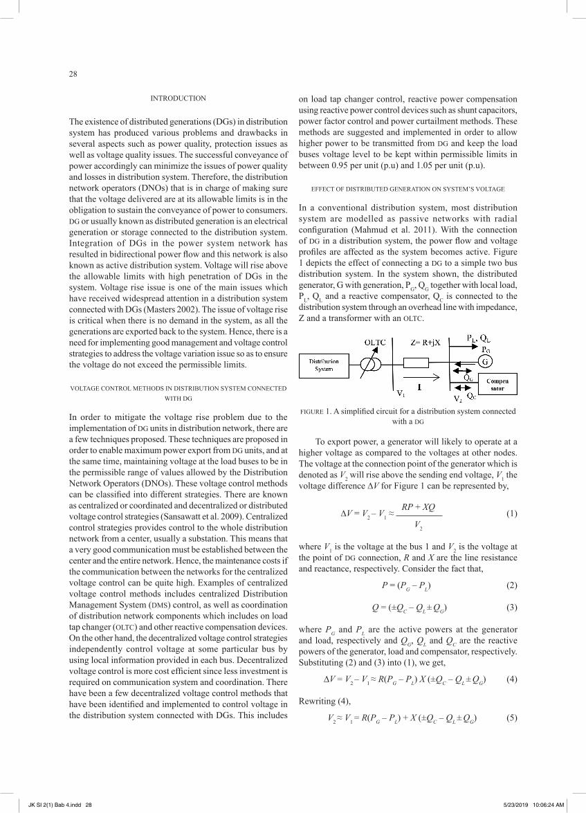
In a conventional distribution system, most distribution system are modelled as passive networks with radial configuration (Mahmud et al. 2011). With the connection of DG in a distribution system, the power flow and voltage profiles are affected as the system becomes active. Figure 1 depicts the effect of connecting a DG to a simple two bus distribution system. In the system shown, the distributed generator, G with generation, PG, QG together with local load, Pl, Ql and a reactive compensator, QC is connected to the distribution system through an overhead line with impedance, Z and a transformer with an OlTC.
FIGURe 1. A simplified circuit for a distribution system connected with a DG
To export power, a generator will likely to operate at a higher voltage as compared to the voltages at other nodes. The voltage at the connection point of the generator which is denoted as V2 will rise above the sending end voltage, V1 the voltage difference ∆V for Figure 1 can be represented by,
RP + XQ ∆V = V2 – V1 ≈ (1)
V2
where V1 is the voltage at the bus 1 and V2 is the voltage at the point of DG connection, R and X are the line resistance and reactance, respectively. Consider the fact that,
P = (PG – PL) (2)
Q = (±QC – QL ± QG) (3)
where PG and PL are the active powers at the generator and load, respectively and QG, QL and QC are the reactive powers of the generator, load and compensator, respectively. Substituting (2) and (3) into (1), we get,
∆V = V2 – V1 ≈ R(PG – PL) X (±QC – QL ± QG) (4)
Rewriting (4),
V2 ≈ V1 = R(PG – PL) + X (±QC – QL ± QG) (5)
JK SI 2(1) Bab 4.indd 28 5/23/2019 10:06:24 AM

29
equation (5) can be used to qualitatively analyze the relationship between the voltage at bus 2 and the amount of distributed generation that can be connected, as well as the impact of the alternative control actions to manage the voltage rise (Strbac et al. 2002).
MeTHODOlOGY
POweR FACTOR CONTROl
Power factor is the ratio between the real power, kw and apparent power, kVA which used in a power system which ranges from the value between 0 to 1. It is a method which is being used to measure power efficiency where the higher the value of the power factor, the more efficient the power usage is. low power factor should be avoided since low power factor values will reduce the lifetime of electrical equipment. This happens as lower power factor actually draws more current compared to higher power factor at the same real power value. Based on the power triangle, power factor can be maximized by lowering the reactive power. Therefore, at no reactive power, apparent power will be equal to the real power. Based on the power factor equation, when real power value is equal to the apparent power value, the power factor is at unity. Unity power factor is the maximum value of power factor coefficient which is 1, which means that power is being used at maximum efficiency. However, in reality, unity power factor is not possible because most of our equipment today are not purely resistive. Most of the power system facilities such as transformer, inductive motors and any inductive load consist of wound coil. This coil acts as an inductor in a circuit and causes lagging power factor, which in return causes power losses and less efficiency to the power system. A capacitive load, however does the opposite of an inductive load. By adding a capacitive load into the circuit, the capacitive load causes leading power factor. Therefore, in order to improve power factor, some industrial sites would install a capacitor bank to compensate the inductive load. By compensating the inductive load, the power factor can be improved (Tenaga Nasional Berhad 2014).
According to (Vovos et al. 2007), it is the responsibility of the network operators in ensuring that all DGs which are connected to the distribution system to operate under the power factor control (PFC) method. The ratio of the real power against the reactive power is kept constant in power factor control (PFC). The main reason of applying PFC is that it is more stable compared to using other network devices, such as the shunt capacitors. On the other hand, the main disadvantage of using PFC is that there is only a certain limit of generation that is allowed to be connected to the system, where if this limit is violated, the voltage will rise above the allowable limit. There are usually three different states of operation that is usually implemented for power factor control with DG. These includes a) unity power factor, b) leading power factor and c) lagging power factor. According to (Jenkins et al. 2000), the terms exporting or importing real and reactive powers is easier to be used rather than using the
terms leading/lagging power factors. The combination of voltage control combined with power factor control is very important in order to ensure that the voltage limits and the power factor for the DG is maintained during light and heavy demand. The operation of both voltage control and power factor control is described by referring to Figure 2.
From the figure, the operating point which is the tip of vector, V always moves along the thick, dashed line. when the voltage approaches its maximum allowable limits, Vmin or Vmax, the PFC will not be used and the DG adjusts the production of reactive power to support the voltage. The generator decreases the P/Q ratio when the voltage drops to the lower threshold, Vmin
PFC. On the other hand, the generator increases the P/Q ratio when the voltage reaches the upper threshold Vmax
PFC. Clearly, by altering the P/Q ratio, the power factor is being changed. However, the operation of the power factor is kept within the minimum (PFmin) and maximum (PFmax) operating power factors.
There are a number of proposed power factor based voltage control methods which have been implemented. One of the methods is the power factor-voltage control (PFC-VC). The PFC-VC is a method which combines two voltage control techniques. As a result of this combination, the control method obtained the advantages of both methods combined (Kiprakis & wallace, 2004). This method combines the behaviour of the DGs operation in two ways, which are the PFC method and voltage control (VC) method. At normal condition, where the measured voltage is within the maximum and minimum allowable limits, the generator will operate in constant PFC mode. On the other hand, when the voltage obtained have breached the allowable limits, the generator will use the voltage control option, which is done by varying the excitation of the automatic voltage regulator. This method which combines the advantages of automatic voltage regulator and PFC is also termed as automatic voltage/power factor control method. According to the regulations set, there are three different modes of power factor operation, namely, unitary, capacitive or inductive power factor adopted by generators to tackle the voltage fluctuation problem (Freitas et al. 2005).
FIGURe 2. Vector diagram representing the generator voltage and current
JK SI 2(1) Bab 4.indd 29 5/23/2019 10:06:25 AM
30
According to (Ochoa et al. 2009) an adaptive PFC has also been implemented as part of an active management work. In this research, it has been proven that the method is able to control voltage while maximising wind power generation. According to (Sansawatt et al. 2009) and (Sansawatt et al. 2010), the input generation to the network is increased while maintaining a fixed unity power factor in order to maintain the voltage level in the system. Several other works which utilizes PFC for voltage regulation includes the work done in (Rahimi et al. 2017). In this work, the Volt-VAR control is applied and compared with PFC in managing voltage rise issues in a distribution system connected with Distributed Renewable energy Resources (DeRs). Other than that, PFC is applied in the work carried out by (Camacho et al. 2013) whereby a more advanced control using effective power factor that is utilizing the control strategy of obtaining the desired reactive power support to control unbalanced grid voltage. In It was found out that the control method is able to successfully maintain maximum active power and able to keep a unity power factor despite the variation in load. In another work, an optimal power flow procedure was done in a medium voltage distribution network with high penetration of DG (Gatta et al. 2015) utilizing the regulation of reactive power generation to ensure that the power factor is maintained at its optimal level. A coordinated voltage control of lRT and DG power factors in distribution network was carried out in (Kamigaich et al. 2016) and it was concluded that the coordination has been
successful in managing the bus voltage magnitudes. On the other hand, an intelligent method of using multi agent system was carried out to perform voltage control in a distribution system by utilizing the coordination of power factors of distributed generators (Shinya & Nagata 2016).
MODellING AND SIMUlATION OF THe Ieee 14 BUS TeST SYSTeM CONNeCTeD wITH DISTRIBUTeD GeNeRATION
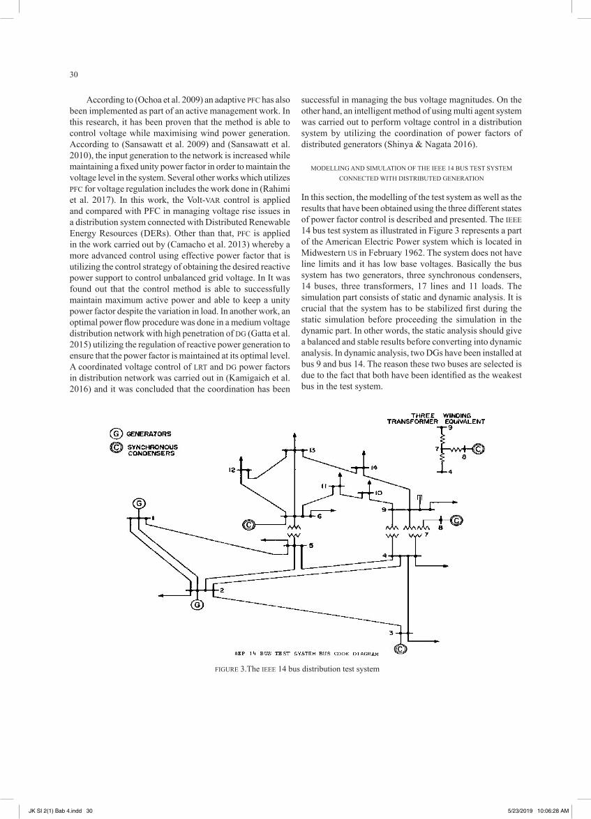
In this section, the modelling of the test system as well as the results that have been obtained using the three different states of power factor control is described and presented. The Ieee 14 bus test system as illustrated in Figure 3 represents a part of the American electric Power system which is located in Midwestern US in February 1962. The system does not have line limits and it has low base voltages. Basically the bus system has two generators, three synchronous condensers, 14 buses, three transformers, 17 lines and 11 loads. The simulation part consists of static and dynamic analysis. It is crucial that the system has to be stabilized first during the static simulation before proceeding the simulation in the dynamic part. In other words, the static analysis should give a balanced and stable results before converting into dynamic analysis. In dynamic analysis, two DGs have been installed at bus 9 and bus 14. The reason these two buses are selected is due to the fact that both have been identified as the weakest bus in the test system.
FIGURe 3.The Ieee 14 bus distribution test system
JK SI 2(1) Bab 4.indd 30 5/23/2019 10:06:28 AM
31
ReSUlTS AND DISCUSSION
BASe CASe SIMUlATION
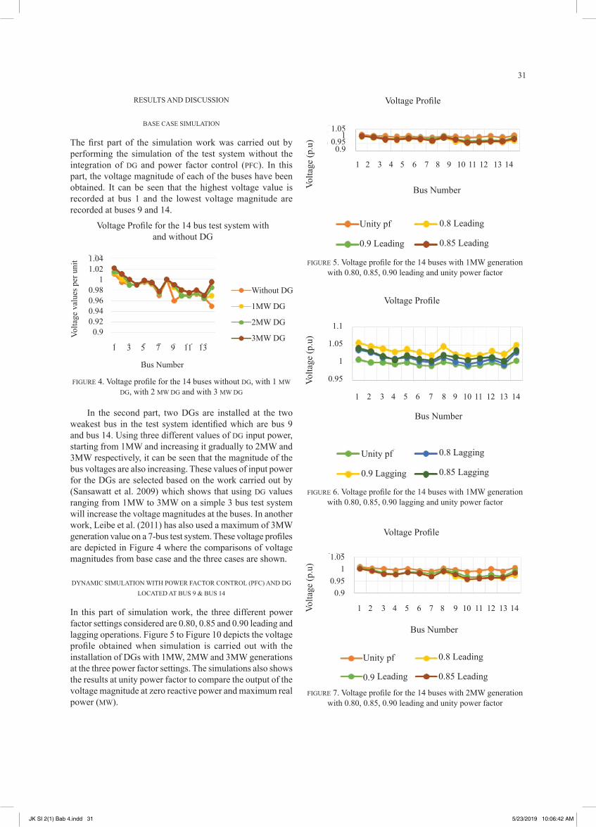
The first part of the simulation work was carried out by performing the simulation of the test system without the integration of DG and power factor control (PFC). In this part, the voltage magnitude of each of the buses have been obtained. It can be seen that the highest voltage value is recorded at bus 1 and the lowest voltage magnitude are recorded at buses 9 and 14.
Voltage Profile for the 14 bus test system with and without DG
1.041.02
10.980.960.940.920.9
1 3 5 7 9 11 13
Bus Number
without DG
1Mw DG
2Mw DG
3Mw DGVolta
ge v
alue
s per
uni
t
FIGURe 4. Voltage profile for the 14 buses without DG, with 1 Mw DG, with 2 Mw DG and with 3 Mw DG
In the second part, two DGs are installed at the two weakest bus in the test system identified which are bus 9 and bus 14. Using three different values of DG input power, starting from 1Mw and increasing it gradually to 2Mw and 3Mw respectively, it can be seen that the magnitude of the bus voltages are also increasing. These values of input power for the DGs are selected based on the work carried out by (Sansawatt et al. 2009) which shows that using DG values ranging from 1Mw to 3Mw on a simple 3 bus test system will increase the voltage magnitudes at the buses. In another work, leibe et al. (2011) has also used a maximum of 3Mw generation value on a 7-bus test system. These voltage profiles are depicted in Figure 4 where the comparisons of voltage magnitudes from base case and the three cases are shown.
DYNAMIC SIMUlATION wITH POweR FACTOR CONTROl (PFC) AND DG lOCATeD AT BUS 9 & BUS 14
In this part of simulation work, the three different power factor settings considered are 0.80, 0.85 and 0.90 leading and lagging operations. Figure 5 to Figure 10 depicts the voltage profile obtained when simulation is carried out with the installation of DGs with 1Mw, 2Mw and 3Mw generations at the three power factor settings. The simulations also shows the results at unity power factor to compare the output of the voltage magnitude at zero reactive power and maximum real power (Mw).
1.051
0.950.9
1 2 3 4 5 6 7 8 9 10 11 12 13 14
Voltage Profile
Bus NumberVolta
ge (p
.u)
Unity pf
0.9 leading
0.8 leading
0.85 leading
FIGURe 5. Voltage profile for the 14 buses with 1MW generation with 0.80, 0.85, 0.90 leading and unity power factor
1.1
1.05
1
0.95
1 2 3 4 5 6 7 8 9 10 11 12 13 14
Voltage Profile
Bus Number
Volta
ge (p
.u)
Unity pf
0.9 lagging
0.8 lagging
0.85 lagging
FIGURe 6. Voltage profile for the 14 buses with 1MW generation with 0.80, 0.85, 0.90 lagging and unity power factor
Voltage Profile
Volta
ge (p
.u)
1.051
0.950.9
1 2 3 4 5 6 7 8 9 10 11 12 13 14
Bus Number
Unity pf
0.9 leading
0.8 leading
0.85 leading
FIGURe 7. Voltage profile for the 14 buses with 2MW generation with 0.80, 0.85, 0.90 leading and unity power factor
JK SI 2(1) Bab 4.indd 31 5/23/2019 10:06:42 AM
32
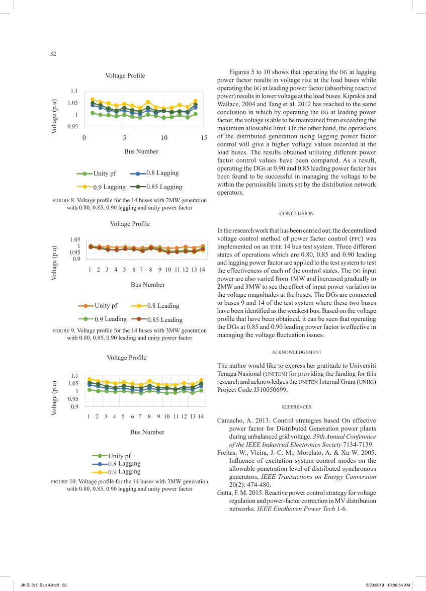
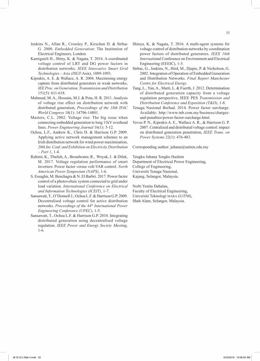
Figures 5 to 10 shows that operating the DG at lagging power factor results in voltage rise at the load buses while operating the DG at leading power factor (absorbing reactive power) results in lower voltage at the load buses. Kiprakis and wallace, 2004 and Tang et al. 2012 has reached to the same conclusion in which by operating the DG at leading power factor, the voltage is able to be maintained from exceeding the maximum allowable limit. On the other hand, the operations of the distributed generation using lagging power factor control will give a higher voltage values recorded at the load buses. The results obtained utilizing different power factor control values have been compared. As a result, operating the DGs at 0.90 and 0.85 leading power factor has been found to be successful in managing the voltage to be within the permissible limits set by the distribution network operators.
CONClUSION
In the research work that has been carried out, the decentralized voltage control method of power factor control (PFC) was implemented on an Ieee 14 bus test system. Three different states of operations which are 0.80, 0.85 and 0.90 leading and lagging power factor are applied to the test system to test the effectiveness of each of the control states. The DG input power are also varied from 1Mw and increased gradually to 2Mw and 3Mw to see the effect of input power variation to the voltage magnitudes at the buses. The DGs are connected to buses 9 and 14 of the test system where these two buses have been identified as the weakest bus. Based on the voltage profile that have been obtained, it can be seen that operating the DGs at 0.85 and 0.90 leading power factor is effective in managing the voltage fluctuation issues.
ACKNOwleDGeMeNT
The author would like to express her gratitude to Universiti Tenaga Nasional (UNITeN) for providing the funding for this research and acknowledges the UNITeN Internal Grant (UNIIG) Project Code J510050699.
ReFeReNCeS
Camacho, A. 2013. Control strategies based On effective power factor for Distributed Generation power plants during unbalanced grid voltage. 39th Annual Conference of the IEEE Industrial Electronics Society 7134-7139.
Freitas, w., Vieira, J. C. M., Morelato, A. & Xu w. 2005. Influence of excitation system control modes on the allowable penetration level of distributed synchronous generators, IEEE Transactions on Energy Conversion 20(2): 474-480.
Gatta, F. M. 2015. Reactive power control strategy for voltage regulation and power-factor correction in MV distribution networks. IEEE Eindhoven Power Tech 1-6.
Voltage Profile
Volta
ge (p
.u)
1.1
1.05
1
0.95
Bus Number
Unity pf
0.9 lagging
0.8 lagging
0.85 lagging
0 5 10 15
FIGURe 8. Voltage profile for the 14 buses with 2MW generation with 0.80, 0.85, 0.90 lagging and unity power factor
Voltage Profile
Volta
ge (p
.u)
1.051
0.950.9
Bus Number
Unity pf
0.9 leading
0.8 leading
0.85 leading
1 2 3 4 5 6 7 8 9 10 11 12 13 14
FIGURe 9. Voltage profile for the 14 buses with 3MW generation with 0.80, 0.85, 0.90 leading and unity power factor
Voltage Profile
Volta
ge (p
.u)
Bus Number
1 2 3 4 5 6 7 8 9 10 11 12 13 14
1.11.05
10.950.9
Unity pf0.8 lagging0.9 lagging
FIGURe 10. Voltage profile for the 14 buses with 3MW generation with 0.80, 0.85, 0.90 lagging and unity power factor
JK SI 2(1) Bab 4.indd 32 5/23/2019 10:06:54 AM
33
Jenkins N., Allan R., Crossley P., Kirschen D. & Strbac G. 2000. Embedded Generation: The Institution of electrical engineers, london.
Kamigaich H., Shiny, K. & Nagata, T. 2016. A coordinated voltage control of lRT and DG power factors in distribution networks. IEEE Innovative Smart Grid Technologies - Asia (ISGT-Asia), 1089-1093.
Kiprakis, A. e. & wallace, A. R. 2004. Maximising energy capture from distributed generators in weak networks, IEE Proc. on Generation, Transmission and Distribution 151(5): 611-618.
Mahmud, M. A., Hossain, M.J. & Pota, H. R. 2011. Analysis of voltage rise effect on distribution network with distributed generation, Proceedings of the 18th IFAC World Congress 18(1): 14796-14801.
Masters, C.l. 2002. Voltage rise: The big issue when connecting embedded generation to long 11kV overhead lines. Power Engineering Journal 16(1): 5-12.
Ochoa, l.F., Andrew K., Chris D. & Harrison G.P. 2009. Applying active network management schemes to an Irish distribution network for wind power maximisation, 20th Int. Conf. and Exhibition on Electricity Distribution – Part 1, 1-4.
Rahimi, K., Tbaileh, A., Broadwater, R., woyak, J. & Dilek, M. 2017. Voltage regulation performance of smart inverters: Power factor versus volt-VAR control. North American Power Symposium (NAPS), 1-6.
S. essaghir, M. Benchagra & N. el Barbri. 2017. Power factor control of a photovoltaic system connected to grid under load variation. International Conference on Electrical and Information Technologies (ICEIT), 1-7.
Sansawatt, T., O’Donnell J., Ochoa l.F. & Harrison G.P. 2009. Decentralised voltage control for active distribution networks. Proceedings of the 44th International Power Engineering Conference (UPEC), 1-5.
Sansawatt, T., Ochoa l.F. & Harrison G.P. 2010. Integrating distributed generation using decentralised voltage regulation. IEEE Power and Energy Society Meeting, 1-6.
Shinya, K. & Nagata, T. 2016. A multi-agent systems for voltage control of distribution networks by coordination power factors of distributed generators. IEEE 16th International Conference on environment and electrical engineering (eeeIC), 1-5.
Strbac, G., Jenkins, N., Hird, M., Djapic, P. & Nicholson, G. 2002. Integration of Operation of embedded Generation and Distribution Networks. Final Report Manchester Centre for Electrical Energy.
Tang, l., Yan, A., Marti, l. & Fuerth, J. 2012. Determination of distributed generation capacity from a voltage regulation perspective, Ieee PeS Transmission and Distribution Conference and Exposition (T&D), 1-8.
Tenaga Nasional Berhad. 2014. Power factor surcharge. Available: http://www.tnb.com.my/business/charges-and-penalties/power-factor-surcharge.html.
Vovos P. N., Kiprakis A. e., wallace A. R., & Harrison G. P. 2007. Centralized and distributed voltage control: impact on distributed generation penetration, IEEE Trans. on Power Systems 22(1): 476-483.
Corresponding author: [email protected]
Tengku Juhana Tengku HashimDepartment of electrical Power engineering,College of engineering,Universiti Tenaga Nasional,Kajang, Selangor, Malaysia.
Nofri Yenita Dahalan,Faculty of electrical engineering,Universiti Teknologi MARA (UiTM),Shah Alam, Selangor, Malaysia.
JK SI 2(1) Bab 4.indd 33 5/23/2019 10:06:55 AM