conceptual design of harvesting energy system for road ... · dalam pendidikan dan latihan teknikal...
TRANSCRIPT
Persidangan Pendidikan (Penyelidikan dan Inovasi) Dalam Pendidikan Dan Latihan Teknikal Dan Vokasional (CiE-TVET 2013) Nombor Prosiding 081
Conceptual Design of Harvesting Energy System for Road Application
Kamarul Faiz bin Mihaj
Kolej Komuniti Segamat 2 Email: [email protected]
Dr. Kok Boon Ching
Universiti Tun Hussein Onn Malaysia Email: [email protected]
Abstract Energy harvesting becomes more and more important in our life. It refers to the practice of acquiring energy from the environment which would be otherwise wasted and converting it into usable electric energy. For this, every kind of energy can be exploited such as solar, wind or strain and kinetic energy. The idea is to propose a conceptual design that will carry out a suitable energy harvesting conversion to be applied for road application. However, harvesting energy using piezoelectric generators has been chosen for this project. The project is conducting a simulation analysis using a piezoelectric generator based on a model by S Roundy et al. The data applied from a 15 mm x 3.2 mm x 0.14 mm single layer piezoelectric bending element which produce 950 μW with a 1.727e6 Nm-2 of input stress. The simulation is done using MATLAB-Simulink-SimPowerSystems. Keywords: Energy harvesting, piezoelectric generator 1.0 Introduction
Energy has always been a most important thing for the development of economy and social growth in country. There are two long-term energy challenges are being faced. One of them is undertaking climate change by mitigating Carbon Dioxide (CO2) emissions and the other one is ensuring a secure clean and affordable energy. As we can see, the usage of fossil fuel for power generation grows each year. These alternative sources are defined as renewable energy. In Malaysia, we are quite familiar with solar panel or photovoltaic which convert the sun’s energy into electrical energy by using a solar cell(s). Recently, renewable energy also comes from non-natural resources which used another technique of energy harvesting. Energy harvesting or power harvesting refers to the practice of acquiring energy from the environment which would be otherwise wasted and converting it into usable electric energy [1].
Energy can also harvested from ambient environment such as mechanical, thermal, light, electromagnetic and also human body to replace traditional sources. Moreover, thermal energy due to temperature gradients and ambient vibrations constitute some of the major sources of energy that has a lot of potential for being harvested. Generally, the first energy harvesting procedure is capturing the energy (resources), storing
1146 | CiE-TVET2013
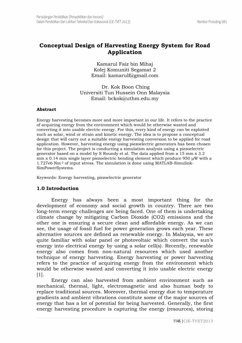
Persidangan Pendidikan (Penyelidikan dan Inovasi) Dalam Pendidikan Dan Latihan Teknikal Dan Vokasional (CiE-TVET 2013) Nombor Prosiding 081 of energy using batteries or other kind of system, and finally the energy will supply power to nearby grid or system as shown in Figure 1.
Figure 1: Energy Harvesting Principle 2.0 Energy Harvesting for Road Application
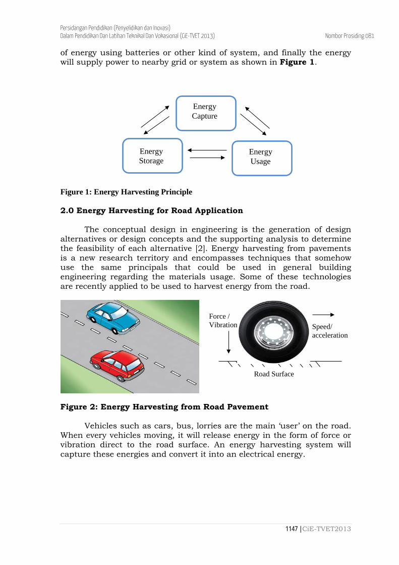
The conceptual design in engineering is the generation of design alternatives or design concepts and the supporting analysis to determine the feasibility of each alternative [2]. Energy harvesting from pavements is a new research territory and encompasses techniques that somehow use the same principals that could be used in general building engineering regarding the materials usage. Some of these technologies are recently applied to be used to harvest energy from the road. Figure 2: Energy Harvesting from Road Pavement
Vehicles such as cars, bus, lorries are the main ‘user’ on the road. When every vehicles moving, it will release energy in the form of force or vibration direct to the road surface. An energy harvesting system will capture these energies and convert it into an electrical energy.
Energy Capture
Energy Storage
Energy Usage
Speed/ acceleration
Road Surface
Force / Vibration
1147 | CiE-TVET2013
Persidangan Pendidikan (Penyelidikan dan Inovasi) Dalam Pendidikan Dan Latihan Teknikal Dan Vokasional (CiE-TVET 2013) Nombor Prosiding 081 2.1 Solar Energy
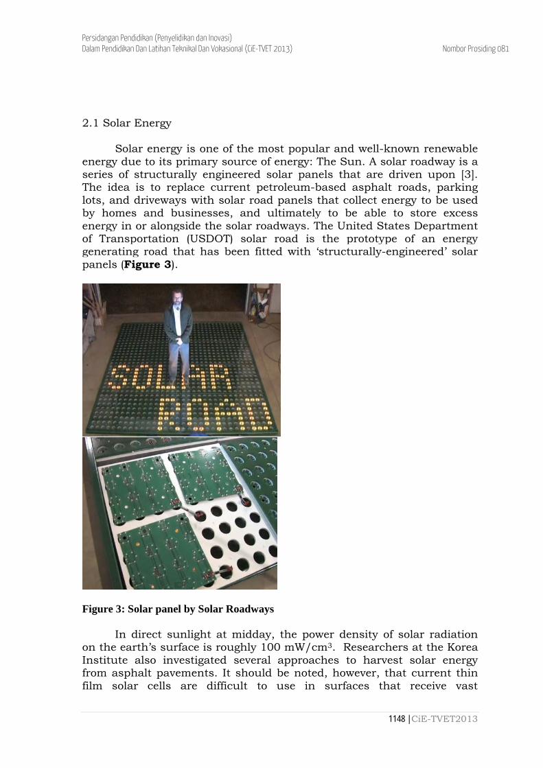
Solar energy is one of the most popular and well-known renewable energy due to its primary source of energy: The Sun. A solar roadway is a series of structurally engineered solar panels that are driven upon [3]. The idea is to replace current petroleum-based asphalt roads, parking lots, and driveways with solar road panels that collect energy to be used by homes and businesses, and ultimately to be able to store excess energy in or alongside the solar roadways. The United States Department of Transportation (USDOT) solar road is the prototype of an energy generating road that has been fitted with ‘structurally-engineered’ solar panels (Figure 3).
Figure 3: Solar panel by Solar Roadways
In direct sunlight at midday, the power density of solar radiation on the earth’s surface is roughly 100 mW/cm3. Researchers at the Korea Institute also investigated several approaches to harvest solar energy from asphalt pavements. It should be noted, however, that current thin film solar cells are difficult to use in surfaces that receive vast
1148 | CiE-TVET2013
Persidangan Pendidikan (Penyelidikan dan Inovasi) Dalam Pendidikan Dan Latihan Teknikal Dan Vokasional (CiE-TVET 2013) Nombor Prosiding 081 mechanical load cycles and environmental conditioning could cause premature corrosion and wear. [4] 2.2 Wind Energy
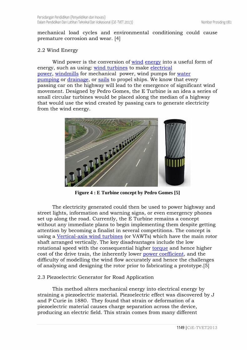
Wind power is the conversion of wind energy into a useful form of energy, such as using: wind turbines to make electrical power, windmills for mechanical power, wind pumps for water pumping or drainage, or sails to propel ships. We know that every passing car on the highway will lead to the emergence of significant wind movement. Designed by Pedro Gomes, the E Turbine is an idea a series of small circular turbines would be placed along the median of a highway that would use the wind created by passing cars to generate electricity from the wind energy.
Figure 4 : E Turbine concept by Pedro Gomes [5]
The electricity generated could then be used to power highway and
street lights, information and warning signs, or even emergency phones set up along the road. Currently, the E Turbine remains a concept without any immediate plans to begin implementing them despite getting attention by becoming a finalist in several competitions. The concept is using a Vertical-axis wind turbines (or VAWTs) which have the main rotor shaft arranged vertically. The key disadvantages include the low rotational speed with the consequential higher torque and hence higher cost of the drive train, the inherently lower power coefficient, and the difficulty of modelling the wind flow accurately and hence the challenges of analysing and designing the rotor prior to fabricating a prototype.[5] 2.3 Piezoelectric Generator for Road Application
This method alters mechanical energy into electrical energy by straining a piezoelectric material. Piezoelectric effect was discovered by J and P Curie in 1880. They found that strain or deformation of a piezoelectric material causes charge separation across the device, producing an electric field. This strain comes from many different
1149 | CiE-TVET2013
Persidangan Pendidikan (Penyelidikan dan Inovasi) Dalam Pendidikan Dan Latihan Teknikal Dan Vokasional (CiE-TVET 2013) Nombor Prosiding 081 sources. For example, the sources could be from human motion, low frequency seismic vibrations and acoustic noise. Moreover, piezoelectricity has the ability of some elements such as crystals and some types of ceramics, to generate an electric potential from a mechanical stress [6].
(a) (b)
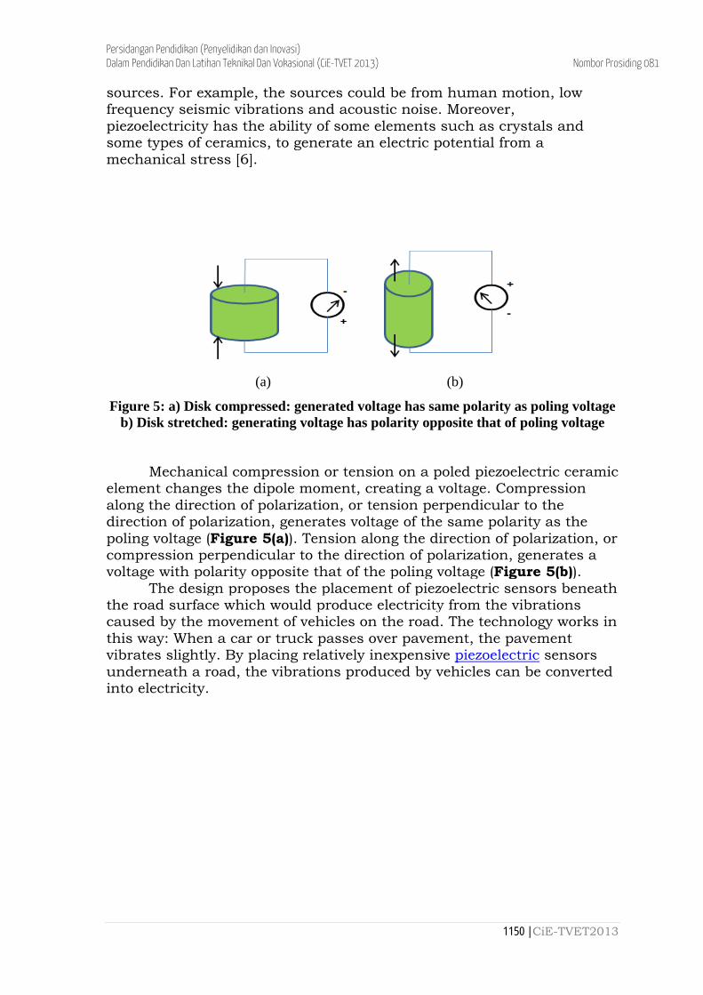
Figure 5: a) Disk compressed: generated voltage has same polarity as poling voltage b) Disk stretched: generating voltage has polarity opposite that of poling voltage
Mechanical compression or tension on a poled piezoelectric ceramic element changes the dipole moment, creating a voltage. Compression along the direction of polarization, or tension perpendicular to the direction of polarization, generates voltage of the same polarity as the poling voltage (Figure 5(a)). Tension along the direction of polarization, or compression perpendicular to the direction of polarization, generates a voltage with polarity opposite that of the poling voltage (Figure 5(b)).
The design proposes the placement of piezoelectric sensors beneath the road surface which would produce electricity from the vibrations caused by the movement of vehicles on the road. The technology works in this way: When a car or truck passes over pavement, the pavement vibrates slightly. By placing relatively inexpensive piezoelectric sensors underneath a road, the vibrations produced by vehicles can be converted into electricity.
1150 | CiE-TVET2013
Persidangan Pendidikan (Penyelidikan dan Inovasi) Dalam Pendidikan Dan Latihan Teknikal Dan Vokasional (CiE-TVET 2013) Nombor Prosiding 081
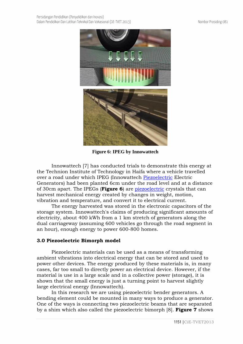
Figure 6: IPEG by Innowattech
Innowattech [7] has conducted trials to demonstrate this energy at
the Technion Institute of Technology in Haifa where a vehicle travelled over a road under which IPEG (Innowattech Piezoelectric Electric Generators) had been planted 6cm under the road level and at a distance of 30cm apart. The IPEGs (Figure 6) are piezoelectric crystals that can harvest mechanical energy created by changes in weight, motion, vibration and temperature, and convert it to electrical current.
The energy harvested was stored in the electronic capacitors of the storage system. Innowattech's claims of producing significant amounts of electricity, about 400 kWh from a 1 km stretch of generators along the dual carriageway (assuming 600 vehicles go through the road segment in an hour), enough energy to power 600-800 homes. 3.0 Piezoelectric Bimorph model
Piezoelectric materials can be used as a means of transforming ambient vibrations into electrical energy that can be stored and used to power other devices. The energy produced by these materials is, in many cases, far too small to directly power an electrical device. However, if the material is use in a large scale and in a collective power (storage), it is shown that the small energy is just a turning point to harvest slightly large electrical energy (Innowattech).
In this research we are using piezoelectric bender generators. A bending element could be mounted in many ways to produce a generator. One of the ways is connecting two piezoelectric beams that are separated by a shim which also called the piezoelectric bimorph [8]. Figure 7 shows
1151 | CiE-TVET2013
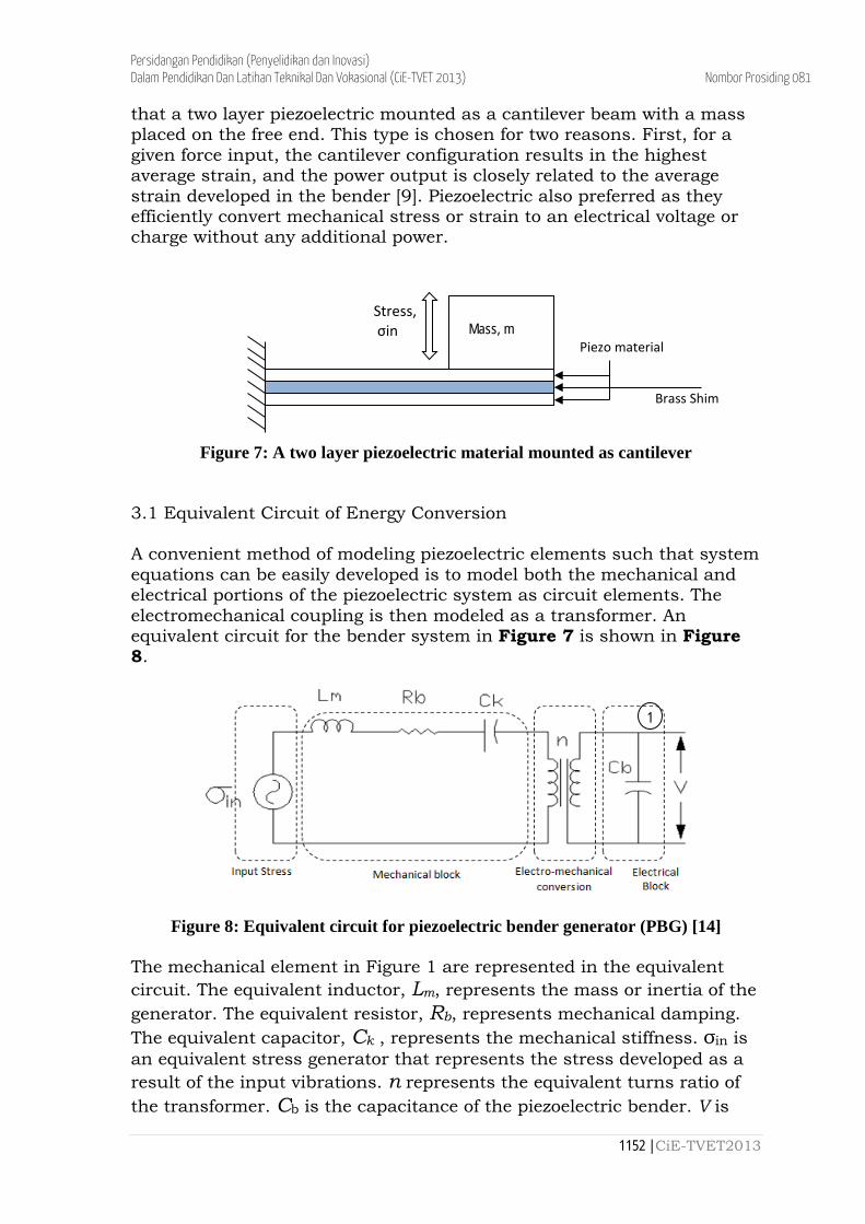
Persidangan Pendidikan (Penyelidikan dan Inovasi) Dalam Pendidikan Dan Latihan Teknikal Dan Vokasional (CiE-TVET 2013) Nombor Prosiding 081 that a two layer piezoelectric mounted as a cantilever beam with a mass placed on the free end. This type is chosen for two reasons. First, for a given force input, the cantilever configuration results in the highest average strain, and the power output is closely related to the average strain developed in the bender [9]. Piezoelectric also preferred as they efficiently convert mechanical stress or strain to an electrical voltage or charge without any additional power.
Figure 7: A two layer piezoelectric material mounted as cantilever 3.1 Equivalent Circuit of Energy Conversion A convenient method of modeling piezoelectric elements such that system equations can be easily developed is to model both the mechanical and electrical portions of the piezoelectric system as circuit elements. The electromechanical coupling is then modeled as a transformer. An equivalent circuit for the bender system in Figure 7 is shown in Figure 8.
Figure 8: Equivalent circuit for piezoelectric bender generator (PBG) [14] The mechanical element in Figure 1 are represented in the equivalent circuit. The equivalent inductor, Lm, represents the mass or inertia of the generator. The equivalent resistor, Rb, represents mechanical damping. The equivalent capacitor, Ck , represents the mechanical stiffness. σin is an equivalent stress generator that represents the stress developed as a result of the input vibrations. n represents the equivalent turns ratio of the transformer. Cb is the capacitance of the piezoelectric bender. V is
Mass, m Piezo material
Brass Shim
Stress, σin
1
1152 | CiE-TVET2013
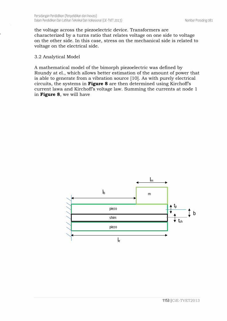
Persidangan Pendidikan (Penyelidikan dan Inovasi) Dalam Pendidikan Dan Latihan Teknikal Dan Vokasional (CiE-TVET 2013) Nombor Prosiding 081 the voltage across the piezoelectric device. Transformers are characterized by a turns ratio that relates voltage on one side to voltage on the other side. In this case, stress on the mechanical side is related to voltage on the electrical side. 3.2 Analytical Model A mathematical model of the bimorph piezoelectric was defined by Roundy at el., which allows better estimation of the amount of power that is able to generate from a vibration source [10]. As with purely electrical circuits, the systems in Figure 8 are then determined using Kirchoff’s current lawa and Kirchoff’s voltage law. Summing the currents at node 1 in Figure 8, we will have
piezo
shim
piezo
m
lm
lb
tp
tsh
b
le
1153 | CiE-TVET2013

Persidangan Pendidikan (Penyelidikan dan Inovasi) Dalam Pendidikan Dan Latihan Teknikal Dan Vokasional (CiE-TVET 2013) Nombor Prosiding 081 Where m is the proof mass and
is the input vibration and k1 is the constant which can be determined by
1154 | CiE-TVET2013
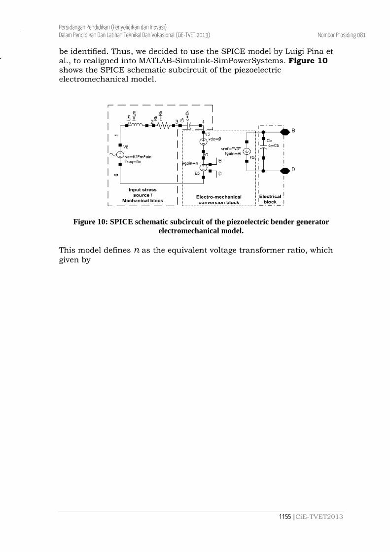
Persidangan Pendidikan (Penyelidikan dan Inovasi) Dalam Pendidikan Dan Latihan Teknikal Dan Vokasional (CiE-TVET 2013) Nombor Prosiding 081 be identified. Thus, we decided to use the SPICE model by Luigi Pina et al., to realigned into MATLAB-Simulink-SimPowerSystems. Figure 10 shows the SPICE schematic subcircuit of the piezoelectric electromechanical model.
Figure 10: SPICE schematic subcircuit of the piezoelectric bender generator electromechanical model.
This model defines n as the equivalent voltage transformer ratio, which given by
1155 | CiE-TVET2013
Persidangan Pendidikan (Penyelidikan dan Inovasi) Dalam Pendidikan Dan Latihan Teknikal Dan Vokasional (CiE-TVET 2013) Nombor Prosiding 081 will also execute the same value to maintain or determine the approximate value which can represent the energy harvesting system. Note that the bimorph prototype is made of two layers of PZT-5H (lead zirconate titanate) with a brass center shim. The center shim is an economical approach to produce a rugged actuator [11]. The data used as below:
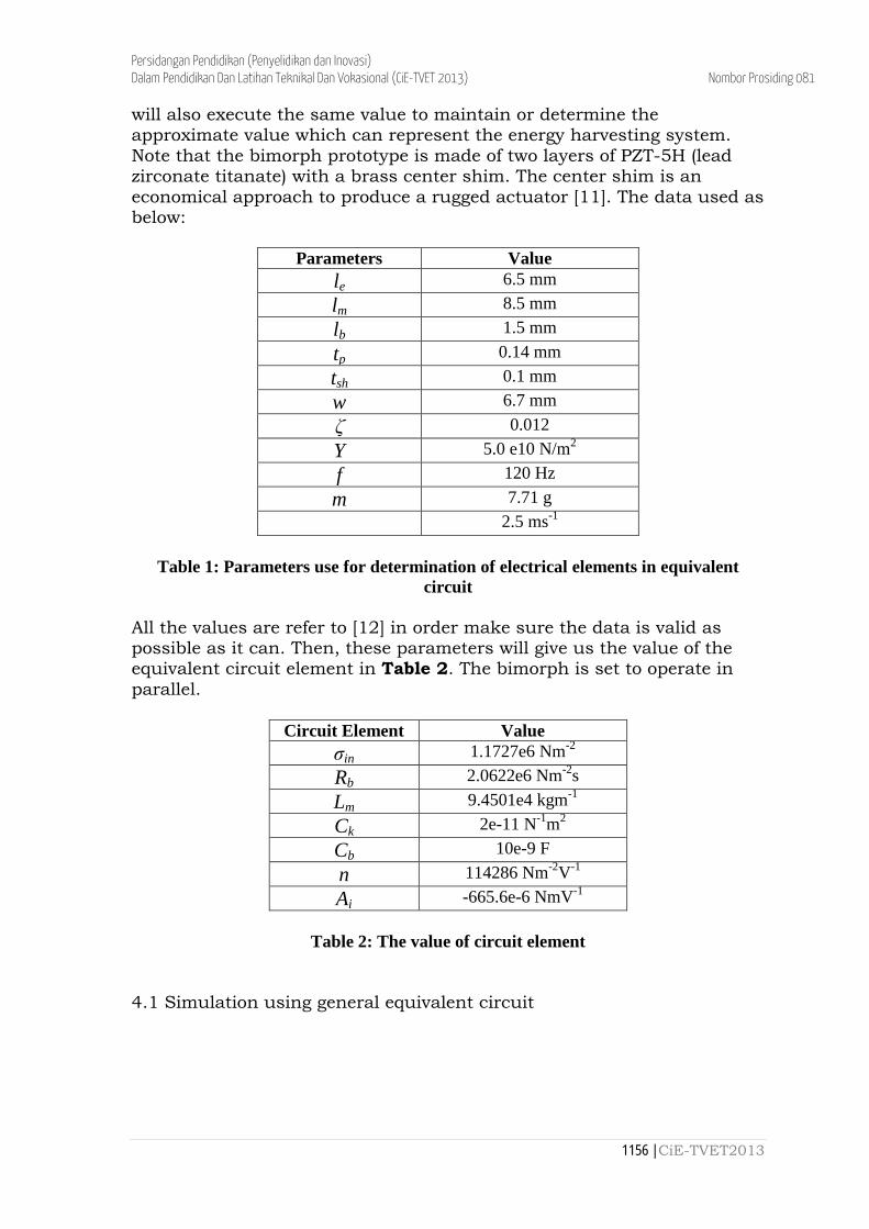
Parameters Value le 6.5 mm lm 8.5 mm lb 1.5 mm tp 0.14 mm tsh 0.1 mm w 6.7 mm ζ 0.012 Y 5.0 e10 N/m2
f 120 Hz m 7.71 g
2.5 ms-1
Table 1: Parameters use for determination of electrical elements in equivalent
circuit All the values are refer to [12] in order make sure the data is valid as possible as it can. Then, these parameters will give us the value of the equivalent circuit element in Table 2. The bimorph is set to operate in parallel.
Circuit Element Value σin 1.1727e6 Nm-2
Rb 2.0622e6 Nm-2s Lm 9.4501e4 kgm-1
Ck 2e-11 N-1m2 Cb 10e-9 F n 114286 Nm-2V-1 Ai -665.6e-6 NmV-1
Table 2: The value of circuit element
4.1 Simulation using general equivalent circuit
1156 | CiE-TVET2013
Persidangan Pendidikan (Penyelidikan dan Inovasi) Dalam Pendidikan Dan Latihan Teknikal Dan Vokasional (CiE-TVET 2013) Nombor Prosiding 081
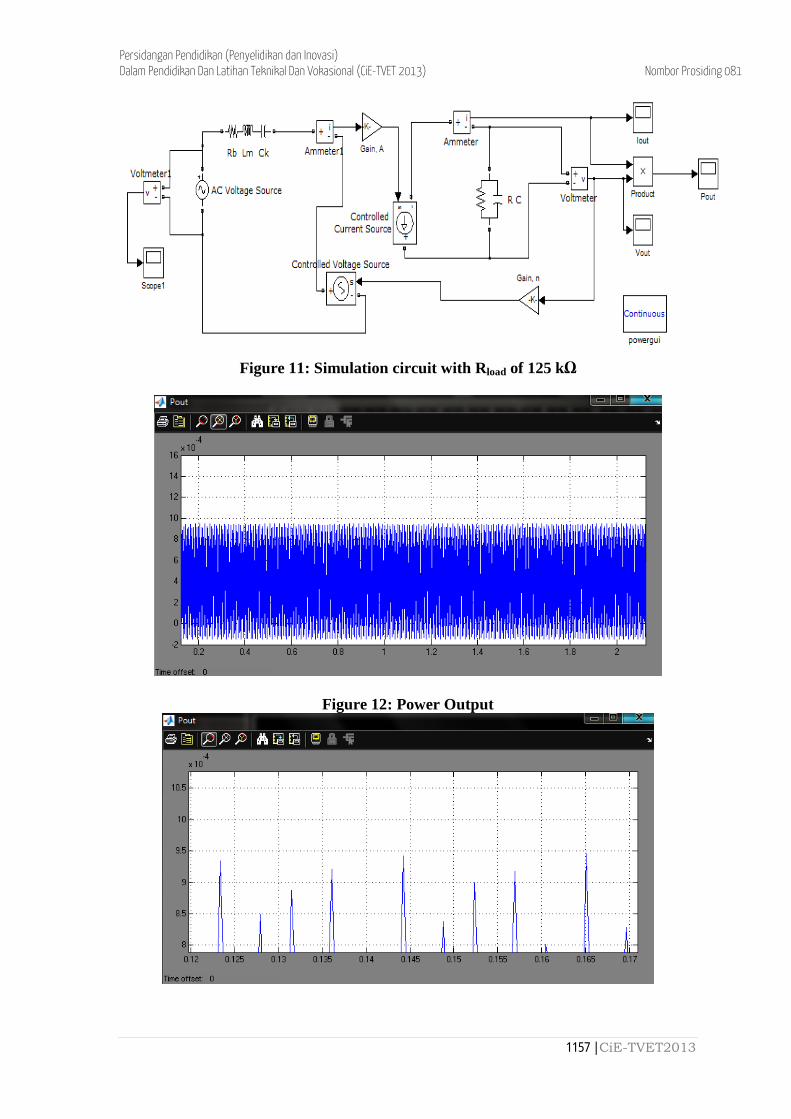
Figure 11: Simulation circuit with Rload of 125 kΩ
Figure 12: Power Output
1157 | CiE-TVET2013
Persidangan Pendidikan (Penyelidikan dan Inovasi) Dalam Pendidikan Dan Latihan Teknikal Dan Vokasional (CiE-TVET 2013) Nombor Prosiding 081
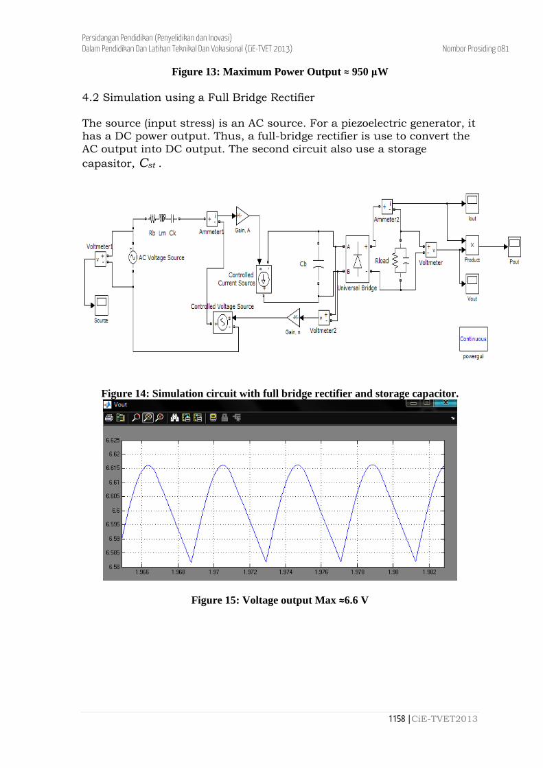
Figure 13: Maximum Power Output ≈ 950 μW 4.2 Simulation using a Full Bridge Rectifier The source (input stress) is an AC source. For a piezoelectric generator, it has a DC power output. Thus, a full-bridge rectifier is use to convert the AC output into DC output. The second circuit also use a storage capasitor, Cst .
Figure 14: Simulation circuit with full bridge rectifier and storage capacitor.
Figure 15: Voltage output Max ≈6.6 V
1158 | CiE-TVET2013
Persidangan Pendidikan (Penyelidikan dan Inovasi) Dalam Pendidikan Dan Latihan Teknikal Dan Vokasional (CiE-TVET 2013) Nombor Prosiding 081
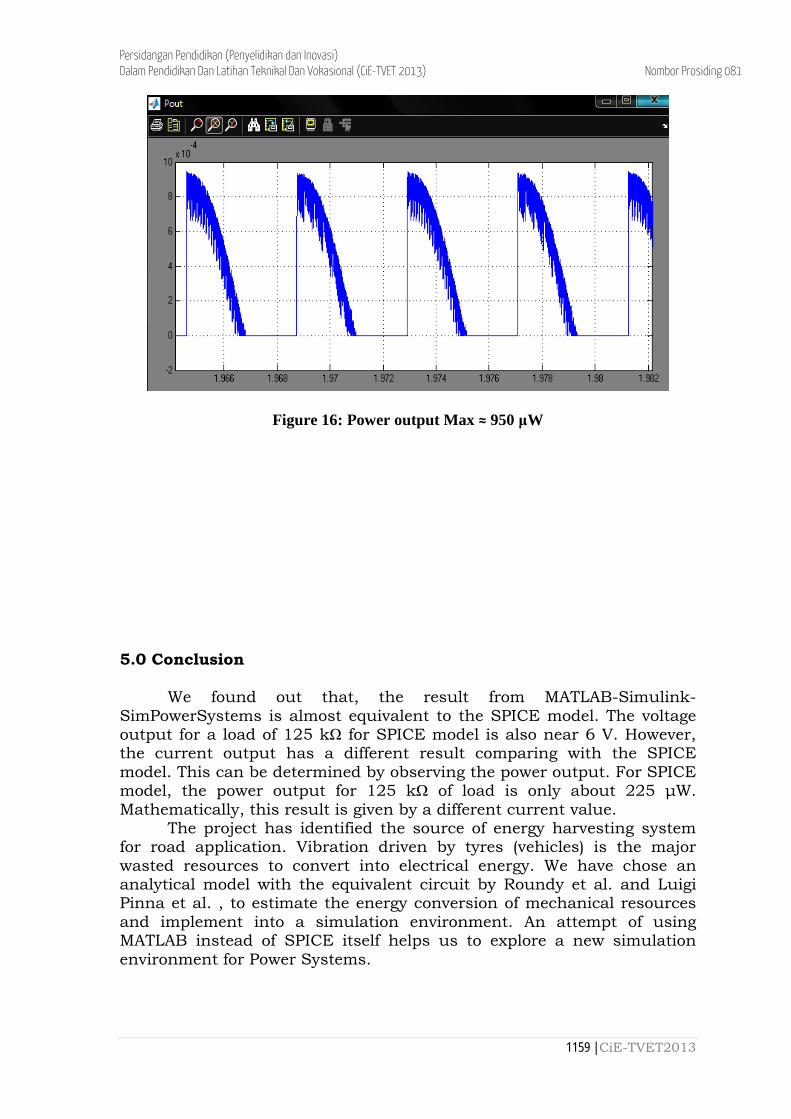
Figure 16: Power output Max ≈ 950 μW 5.0 Conclusion
We found out that, the result from MATLAB-Simulink-SimPowerSystems is almost equivalent to the SPICE model. The voltage output for a load of 125 kΩ for SPICE model is also near 6 V. However, the current output has a different result comparing with the SPICE model. This can be determined by observing the power output. For SPICE model, the power output for 125 kΩ of load is only about 225 μW. Mathematically, this result is given by a different current value.
The project has identified the source of energy harvesting system for road application. Vibration driven by tyres (vehicles) is the major wasted resources to convert into electrical energy. We have chose an analytical model with the equivalent circuit by Roundy et al. and Luigi Pinna et al. , to estimate the energy conversion of mechanical resources and implement into a simulation environment. An attempt of using MATLAB instead of SPICE itself helps us to explore a new simulation environment for Power Systems.
1159 | CiE-TVET2013

Persidangan Pendidikan (Penyelidikan dan Inovasi) Dalam Pendidikan Dan Latihan Teknikal Dan Vokasional (CiE-TVET 2013) Nombor Prosiding 081 6.0 Suggestion We found out that, technical reports on large scale of piezoelectric usage are seldom found in the power generation field. Future work would involve: i. Indepth analysis for the energy conversion using others applicable model ii. Analysis of energy from tyres (vehicles); force, vibration, frequency etc. iii. Compatibility of the energy to suit the piezoelectric generator; robust, resilience etc. iv. Experimental work for piezoelectric on road pavement; maintenance, environment etc.
1160 | CiE-TVET2013
Persidangan Pendidikan (Penyelidikan dan Inovasi) Dalam Pendidikan Dan Latihan Teknikal Dan Vokasional (CiE-TVET 2013) Nombor Prosiding 081 References [1] Y C Shu, I C Lien, Analysis of power output for piezoelectric energy harvesting systems, Institue of Physics Publishing, Smart Material and Stuctures vol 15, 2006 [2] Klipsch School of Electrical & Computer Engineering, Engineering Design Notes III-Conceptual Design, New Mexico State University, 2007 [3] Solar Roadway, http://en.wikipedia.org/wiki/Solar_roadway [4] Andriopoulou Symeoni, A Review on Energy Harvesting from Roads, http://kth.diva-portal.org/smash/get/diva2:549685/FULLTEXT01, 2012 [5] Michael C Brower, Nicholas M Robinson et al, Wind Flow Modeling Uncertainty, Aws Truepower, New York 2010 [6] Faruk Yildiz, Potential Ambient Energy-Harvesting Sources and
Techniques, The Journal of Technology Studies, Sam Houston State
University, Huntsville Texas
[7] Innowattech Energy Harvesting System, www.innowattech.co.il [8] Mahmoud Al Ahmad, Amro M. Elshurafa et al, Determination of Maximum Power Transfer Conditions of Bimorph Piezoelectric Energy Harvesters, King Abdullah University of Science & Technology, Saudi Arabia, 2012 [9] S Roundy, P K Wright, A Piezoelectric vibration based generator for wirelesss electronics, University of California, USA, 2004 [10] Luigi Pinna et al., SPICE Model for Piezoelectric Bender Generators, University of Genoa, Italy, 2009 [11] Brass Reinforced Piezoelectric Bending Sensors (Generators), http://piezo.com/prodbg1brass.html [12] Shadrach Joseph Roundy, Energy Scavenging for Wireless Sensor Nodes with a Focus on Vibration to Electricity Conversion, PhD Thesis, The University of California, Berkeley, 2003
1161 | CiE-TVET2013