zulfadli bin kasmani -...
TRANSCRIPT
SIMULATION OF AUTOMATIC STEERING SYSTEM
ZULFADLI BIN KASMANI
UNIVERSITI TEKNIKAL MALAYSIA MELAKA
‘Saya/Kami* akui bahawa telah membaca
karya ini dan pada pandangan saya/kami* karya ini
adalah memadai dari segi skop dan kualiti untuk tujuan penganugerahan
Ijazah Sarjana Muda Kejuruteraan Mekanikal (Automotif)
Tandatangan :
Nama Penyelia 1 :
Tarikh :
Tandangan :
Nama Penyelia 2 :
Tarikh :
* Potong yang mana tidak berkenaan
SIMULATION OF AUTOMATIC STEERING SYSTEM
ZULFADLI BIN KASMANI
Laporan ini dikemukan sebagai
memenuhi sebahagian daripada syarat penganugerahan
Ijazah Sarjana Muda Kejuruteraan Mekanikal (Automotif)
Fakulti Kejuruteraan Mekanikal
Universiti Teknikal Malaysia Melaka
APRIL 2010
ii
“I admit that this report is from my own work and idea except for the summary and a
few sections which were extracted from other resources as being mention”
Signature :……………………..
Writer Name :……………………..
Date :……………………..
iii
This final year project report is dedicated to my lovely parents, who has given
countless efforts in motivating me during my 4 years undergraduate studies. and also
to all my friends burning the midnight oil for countless nights in order to fulfill the
project requirements. may we someday materializing our dreams in becoming
successful engineers. ameen.
iv
ACKNOWLEDGEMENT
I would like to express my highest gratitude to my project supervisor, Dr.
Khizbullah Hudha for his countless guidelines and motivation to ensure the
completion of the project. Not to forget his constant financial support in order to
materialize the requirement of the project. This project cannot be completed without
the assistance of master students, Mr. Zubir and Mr. Em Poh Ping and I should thank
them personally for all the informations regarding the project.
Cooperation from my friends, lecturers, or laboratory technicians directly or
indirectly in assisting me during the project is greatly appreciated. Hopefully this
final year project report successfully serves as a valuable source and guidelines for
junior students.
v
ABSTRAK
Sistem stereng automotif telah mengalami revolusi selama beberapa dekad
berikutan aplikasi elektronik yang telah mengubah rekabentuk sistem stereng biasa.
Kemajuan sistem stereng yang telah membawa kepada penciptaan stereng automatik
dimulakan dengan sistem stereng hidraulik yang diubahsuai kepada sistem stereng
elektrohidraulik kepada penciptaan sistem stereng elektrik dan akhirnya kepada
stereng dengan wayar (SBW). Stereng automatik telah menukar kesemua sistem
tersebut dengan menyingkirkan hubungan mekanikal antara stereng syaf dengan
stereng rack. Skop kajian projek ini berkisar tentang permodelan matematik sistem
stereng automatic dengan menggunakan model Simulink di MATLAB dan untuk
mengesahkan ciri-ciri stereng automatik. Walaubagaimanapun, kerana tiada model
ujian yang telah direkabentuk, projek ini juga berkisar tentang rekabentuk model
ujian untuk sistem stereng automatic. Kerana kos dan rekabentuk yang mudah,
sistem stereng dan suspensi Perodua Kancil telah dipilih untuk eksperimen. Projek
ini diteruskan dengan permodelan kenderaan 9 DOF berdasarkan beberapa jurnal dan
seminar persidangan. Untuk mengesahkan permodelan kenderaan yang dicadangkan,
CarSim telah dipilih sebagai tujuan perbandingan. Permodelan pemandu beserta
kawalan PID telah dibangunkan dan projek seterusnya diteruskan dengan
menganalisis dan mengesahkan ciri-ciri stereng automatik daripada permodelan
kenderaan yang dicadangkan di dalam MATLAB Simulink. Keputusan simulasi
telah mengesahkan bahawa permodelan kenderaan yang dicadangkan telah
menunjukkan ciri-ciri stereng automatik di dalam MATLAB Simulink.
vi
ABSTRACT
The automotive steering system has been evolved for several decades due to
the electronics revolution which has changed completely the landscape of
conventional steering system. The development of steering system that leads to the
creation of automatic steering system can be portrayed as pure mechanical steering
system developed to hydraulic power steering to electrohydraulic power steering to
electric power steering (EPS) and finally to SBW system. Automatic steering system
has changed completely the aforementioned systems by eliminating the mechanical
connection of steering shaft to the steering rack. The scope of the research project is
to construct the mathematical modeling of automatic steering system using Simulink
Models in MATLAB for simulation and to verify the automatic steering behavior of
simulated vehicle model in MATLAB Simulink. Although the project scope lies
between mathematical modeling and simulation, the project also covers the design of
automatic steering test rig since there is no existing test rig to be experimented. Due
to the simplicity of steering system mechanisms and lower cost, Perodua Kancil
steering and suspension system has been chosen to be experimented. The design
development of automatic steering test rig covers the conceptual design phases
before final design is produced to be fabricated. The project continues with the
development of 9 DOF vehicle model derived from several journals and conference
proceedings. To verify the proposed vehicle model, CarSim has been chosen for
comparison purpose. The driver model integrated with PID controllers which
functions as the vehicle model controller is developed before the automatic steering
behavior of simulated vehicle model is analyzed and verified in MATLAB Simulink.
Simulation results have verified that the proposed vehicle model has shown the
automatic steering behavior in MATLAB Simulink.
vii
TABLE OF CONTENT
CHAPTER TITLE PAGE
CONFESSION ii
DEDICATION iii
ACKNOWLEDGEMENT iv
ABSTRAK v
ABSTRACT vi
CONTENTS vii
LIST OF TABLE xii
LIST OF FIGURES xiii
LIST OF APPENDICES xvii
CHAPTER 1 INTRODUCTION 1
1.1 Background 1
1.2 Problem Statement 2
1.3 Objective 3
1.4 Scope 3
viii
CHAPTER 2 LITERATURE REVIEW 4
2.1 Evolution of Automotive Steering 4
System
2.1.1 Hydraulic Power Assisted Steering 5
2.1.2 Electrohydraulic Power Assisted 6
Steering
2.1.3 Electronically-Controlled Power 7
Assisted Steering
2.1.4 Electric Power Assisted Steering 8
2.2 Steer by Wire (SBW) 9
2.2.1 Active Steering- The Pathway to SBW 9
2.2.2 Introduction to Steer by Wire (SBW) 11
2.2.3 Basic Structure of SBW 12
2.2.4 Previous Research Analysis of SBW 15
System
2.2.5 Technical Advantages of SBW System 17
2.2.6 Constraints of SBW System 19
2.3 Automatic Steering Sytem 20
2.3.1 The Control Structure of Automatic 20
Steering System
2.3.2 The Advantages of Automatic Steering 22
System
ix
CHAPTER 3 METHODOLOGY 23
3.1 Flowchart and Task Explanation 23
3.2 Equipment and Technical Specifications 27
3.2.1. Perodua Kancil Steering System 27
3.2.2 Perodua Kancil Suspension System 27
3.2.3 Automatic Steering System Test Rig 28
3.2.4 DC Stepping Motor 29
3.3 Instrumentation 30
3.3.1 TR1 Accu-Coder 30
3.3.2 Linear Variable Displacement 31
Transducer (LVDT)
3.3.3 Laboratory DC Power Supply 32
3.3.4 Personal Computer (PC) 33
3.3.5 DAQ Module 33
3.4 Experimental Setup and Procedures 34
3.5 Development of Automatic Steering 35
System Test Rig
3.5.1 Conceptual Design 35
3.5.2 Design Criterions 35
3.5.3 Conceptual Design Evaluation 36
3.5.4 Scoring Matrix 39
x
3.5.5 Detail Design of Automatic Steering 40
Test Rig
3.6 Overview of Closed Loop Control Systems 41
3.7 Development of Automatic Steering Control 42
System
3.7.1 Development of Vehicle Model 43
3.7.2 Ride Model 44
3.7.3 Handling Model 45
3.7.4 Calspan Tire Model 47
3.7.5 Tire Sideslip Model 49
3.7.6 Roll and Pitch Model 50
3.7.7 X-Trajectory and Y-Trajectory Model 51
3.8 Description of Simulation Model 52
3.8.1 9 DOF Vehicle Model 52
3.8.2 Driver Model 53
CHAPTER 4 RESULTS 54
4.1 Detail Design of SBW Test Rig 54
4.2 Simulation Results of Vehicle Model 57
4.3 Verification of Vehicle Model 61
4.4 Simulation Results of Automatic Steering System 65
xi
CHAPTER 5 DISCUSSION 67
5.1 Simulation Results of Vehicle Model 67
5.2 Verification of Vehicle Model 69
5.3 Simulation Results of Automatic Steering System 70
CHAPTER 6 CONCLUSION 72
6.0 Overview 72
6.1 Recommendation 73
REFERENCES 74
BIBLIOGRAPHY 76
APPENDIX 77
xii
LIST OF TABLES
NO TITLE
PAGE
3.1 Technical Specifications of DC 29
Stepping Motor
3.2 LVDT Technical Specifications 32
3.3 Concept Designs Scoring Matrix 39
xiii
LIST OF FIGURES
NO TITLE
PAGE
2.1 Automotive Applications For By 5
Wire Technology
2.2 Hydraulic Power Steering System 6
2.3 Speed-Dependent Power Assisted Steering 7
2.4 Schematic Diagram of Electric Power 8
Steering
2.5 BMW Active Steering System 10
2.6 1972 F-8 DFBW in Flight 11
2.7 Conversion between Conventional Steering 12
System and SBW System
2.8 Basic Architecture of SBW System 14
2.9 Basic Control Diagram for SBW 14
2.10 Rack-Actuating Steer by Wire System 15
2.11 Comparison between Conventional Steering and 17
Active Steering
xiv
2.12 The Effect of Lateral Forces under Automatic 19
Steering Correction
2.13 The Complete Structure of Automatic Steering System 21
3.1 Flowchart 25
3.2 Rack & Pinion Steering System 27
and Specifications
3.3 Perodua Kancil Front Suspension System 28
3.4 Automatic Steering System Test Rig 28
3.5 2 Phase DC 3A Vexta Stepping Motor 29
and Driver
3.6 2 Phase DC 3A Vexta Stepping Motor 30
Dimension
3.7 TR1 Accu-Coder 30
3.8 TR1 Accu-Coder Dimension 31
3.9 LVDT 31
3.10 Laboratory DC Power Supply Unit 32
3.11 Personal Computer (PC) 33
3.12 List of Some Common Phenomenon 33
and Transducers
3.13 DAQ Module 34
3.14 Schematic Diagram of Experimental Setup 34
3.15 Concept Design 1 36
3.16 Concept Design 2 37
3.17 Concept Design 3 37
3.18 Concept Design 4 38
xv
3.19 Overview of Closed Loop Control System 41
3.20 The Proposed Control Structure of Automatic Steering 42
3.21 The Proposed Inner Loop Controller of Automatic 43
Steering
3.22 SAE Vehicle Axis System 43
3.23 Graphical Representation of Vehicle Ride Model 44
3.24 7 DOF Vehicle Handling Model 45
3.25 SAE Tire Coordinate System 47
3.26 Tire Slip Angle 49
3.27 The Complete 9 DOF Vehicle Model 52
3.28 The Complete Control Structure of Automatic Steering 53
4.1 Isometric View of SBW Test Rig 54
4.2 Top View of SBW Test Rig 55
4.3 Front View of SBW Test Rig 55
4.4 Left View of SBW Test Rig 56
4.5 Graph of x-trajectory against time 58
4.6 Graph of y-trajectory against time 58
4.7 Graph of lateral acceleration against time 59
4.8 Graph of yaw angle against time 59
4.9 Graph of roll angle against time 60
4.10 Graph of x-trajectory against time 62
4.11 Graph of y-trajectory 62
4.12 Graph of lateral acceleration against time 63
4.13 Graph of yaw angle against time 63
xvi
4.14 Graph of roll angle against time 64
4.15 Graph of y-trajectory against time 65
4.16 Graph of positioning error against time 66
4.17 Graph of y-trajectory against time 66
xvii
LIST OF APPENDICES
Appendix 1 Calspan Tire Model Parameters 77
Appendix 2 Vehicle Model Simulation Parameters 77
Appendix 3 PID Controller Parameters 78
Appendix 4 Schematic Drawing of ISO 3888-1 Double 78
Lane Change Test Course
Appendix 5 Predefined Double Lane Change Maneuver 78
Path in Lookup Table Obtained from CarSim
at 80 km/h Constant Speed
1
CHAPTER 1
INTRODUCTION
1.1 Background
The purpose of this project is to investigate and evaluate automatic steering
system of driverless vehicle by means of simulation through the development of
mathematical model of Automatic Steering System in MATLAB.
The purpose of steering system is to turn the front wheels. It also helps
maneuvering the vehicles in desired lateral directions such as switching lanes,
rounding sharp turns, and avoiding roadway obstacles. In some cases, steering
system can also be used to turn the rear wheels, as recent technological development
have shown that Four Wheel Steering (4WS) is practically viable in automotive
steering system. However, as the project is focused primarily on front wheel steering,
Four Wheel Steering (4WS) will not be presented on this paper.
Automobile steering systems can be classified under two systems, which are
the less commonly used recirculating ball steering system and rack and pinion
steering system which can be considered the most commonly found in automobile.
Focusing on rack and pinion steering system, we could discover that various
technological advancements have been implemented into the system such as
2
hydraulic assisted rack and pinion steering system, electrohydraulic steering system,
electric power steering, and the recent state-of-the-art active steering system.
However, those aforementioned systems still retaining mechanical linkages
found in conventional steering system such as steering column and steering shaft.
Automatic Steering System presents a major challenge as well as major breakthrough
discoveries in automotive steering technology by eliminating completely mechanical
connection found in conventional steering system. The pinion shaft of the steering
wheel that produces steering rack displacement has been substituted by an electric
motor that controls the front wheels angle. For general definition, automatic steering
system of driverless vehicle can be defined as an autonomous motion of the vehicle
which is following the desired trajectory path specified by the driver.
1.2 Problem Statement
One of the contributing factors that mobilize me to choose Automatic
Steering System as final year research is due to its various future advantages that
eliminate various drawbacks regarding conventional steering system. Since
Automatic Steering System uses electric motor to produce road wheel rotation, it is
different from conventional hydraulic steering system which causes major
inefficiency to the engine since the hydraulic pump is a constant engine driven pump
regardless whether the car is stationary or in motion. Additionally, the steering shaft
is also a major problem in terms of safety since the impact from frontal crash will
exert the force to the steering wheel via steering shaft, injuring or killing the driver
instantly. By the introduction of Automatic Steering System, which eliminates
completely mechanical connection (steering shaft) found in conventional steering
system, it has a potential to improve the safety of automobile. Various advantages of
implementing the automatic steering system of driverless vehicle such as the
implementation of driver model, ITS (intelligent transportation system), and
automobile safety related issues will be discussed further in this paper.
3
1.3 Objective
• To develop the driver model with PID controller.
• To verify the automatic steering behavior of simulated vehicle model in
MATLAB Simulink.
1.4 Scope
• Development of 9 Degree of Freedom (9 DOF) vehicle model in
MATLAB Simulink.
• Verification of vehicle model with Carsim Educational Vehicle
Dynamics Software.
• Development of driver model with PID controllers which function as
vehicle model controller.
• Verify the automatic steering behavior of simulated vehicle model in
MATLAB Simulink.
4
CHAPTER 2
LITERATURE REVIEW
2.1 Evolution of Automotive Steering System
The steering mechanisms can be defined as converting the driver’s rotational
input at the steering wheel into a change in steering angle of the vehicle steering road
wheels. According to Paul Yih (2005), the basic design in automotive steering
system began with the invention of steering wheel on which the driver’s steering
input is transmitted by a shaft through some type of gear reduction mechanisms
(generally refers to rack & pinion steering system). This system that will later
generate steering motion at the front wheels can be precisely described as purely
mechanical steering system.
However, advances in electronics have revolutionized many aspects of
automotive engineering, especially in the areas of engine combustion management
and vehicle safety systems such as Anti-Lock Braking System (ABS), Electronic
Stability Control (ESC), and Adaptive Cruise Control (ACC). Various benefits have
been identified by applying electronic technology for automotive application:
improved performance, safety, and reliability with reduced manufacturing and
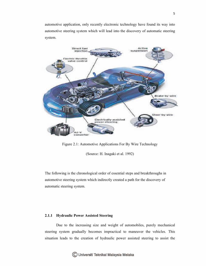
operating costs. Unlike Throttle By Wire (also known as Electronic Throttle Control)
and Brake By Wire (also known as Electrohydraulic Brakes, EHB/Electromechanical
Brakes, EMB) as described in figure 2.1 which have been implemented in
5
automotive application, only recently electronic technology have found its way into
automotive steering system which will lead into the discovery of automatic steering
system.
Figure 2.1: Automotive Applications For By Wire Technology
(Source: H. Inagaki et al. 1992)
The following is the chronological order of essential steps and breakthroughs in
automotive steering system which indirectly created a path for the discovery of
automatic steering system.
2.1.1 Hydraulic Power Assisted Steering
Due to the increasing size and weight of automobiles, purely mechanical
steering system gradually becomes impractical to maneuver the vehicles. This
situation leads to the creation of hydraulic power assisted steering to assist the