the implementation of sinusoidal pwm on...
TRANSCRIPT
THE IMPLEMENTATION OF SINUSOIDAL PWM ON SINGLE PHASE
5-LEVEL CASCADED H-BRIDGE MULTILEVEL INVERTER
MUHAMAD FAIZAL BIN YAAKUB
A project report submitted in partial fulfillment of the requirements for the award
of Master of Electrical Engineering
Faculty of Electrical and Electronic Engineering
Universiti Tun Hussein Onn Malaysia
FEBRUARY 2013
v
ABSTRACT
In the new millennium era of technology, modern industrial devices are mostly based on
electronic devices that are very sensitive to harmonics. The needs for a free-harmonics
and high rating power source is extremely increased in the past few years to meet the
requirement from the industries. An inverter which converts DC power to AC power is
one of the power electronic devices that have been in the researchers’ radar for further
improvement to generate a clean power source. An inverter can be broadly classified
into single level inverter and multilevel inverter. A multilevel inverter as compared to a
single level inverter has advantages like minimum harmonics distortion and higher
power output. An implementation of cascaded h-bridge topology and a sinusoidal pulse-
width modulation, synthesize a higher quality output power especially with multilevel
configuration.

vi
ABSTRAK
Dalam era teknologi alaf baru, peralatan industri moden kebanyakannya adalah
berasaskan kepada peranti elektronik yang mana amat sensetif kepada harmonik.
Keperluan kepada bekalan kuasa yang bebas harmonik serta mempunyai kadar kuasa
tinggi meningkat secara mendadak semenjak beberapa tahun kebelakangan ini untuk
memenuhi permintaan yang tinggi daripada penggiat industri. Pengubah yang berfungsi
menukar kuasa arus terus kepada kuasa ulang alik merupakan salah satu peralatan yang
telah menjadi tumpuan para penyelidik untuk tujuan menaik taraf keyupayaannya serta
untuk tujuan penjaanan kuasa elektrik yang berkualiti. Pengubah secara asasnya boleh
diklasifikasikan kepada dua, iaitu pengubah satu peringkat dan pengubah pelbagai
peringkat. Pegubah pelbagai peringakt mempunyai pelbagai kelebihan jika dibandingkan
dengan pengubah satu peringkat. Contohnya, gangguan harmonik yang rendah serta
kuasa keluaran yang lebih tinggi. Dengan menggunakan kaedah topologi Cascaded H-
bridge dan sinusoidal pulse-width modulation, konfigurasi pengubah pelbagai peringkat
dapat menghasilkan kuasa keluaran yang lebih berkualiti.

vii
CONTENTS
TITLE i
DECLARATION ii
DEDICATION iii
ACKNOWLEDGEMENT iv
ABSTRACT v
ABSTRAK vi
TABLE OF CONTENTS vii
LIST OF TABLES x
LIST OF FIGURES xi
LIST OF ABBREVIATIONS & SYMBOLS xiv
LIST OF APPENDICES xvi
CHAPTER 1 INTRODUCTION 1
1.0 Chapter Overview 1
1.1 The Work 1
1.2 Multilevel Converter 2
1.3
1.4
1.5
1.6
1.7
1.8
Multilevel Inverter Applications
Merits and Demerits of Multilevel Inverter
The Switching
Problem Statement
The Aims
Project Scope
3
6
6
7
8
8
viii
1.9 Thesis Outline 8
CHAPTER 2 LITERATURE REVIEW 10
2.0
2.1
Chapter Overview
The Inverter and Multilevel Inverter
10
10
2.1.1 The Inverter 10
2.1.2 The Multilevel Inverter 11
2.1.3 Cascaded H-bridge Multilevel Inverter 14
2.2
2.3
Sinusoidal Pulse Width Modulation
Previous Research
16
19
CHAPTER 3 METHODOLOGY 23
3.0 Chapter Overview 23
3.1 Milestone 1: Inverter Modelling 23
3.2 Milestone 2: Control Scheme and Algorithm
Development
24
3.3 Milestone 3: Hardware Development 25
3.4 Milestone 4: System Integration and Data Collection 26
CHAPTER 4 MODELLING AND SIMULATION 27
4.0 Simulink SimPowerSystem 27
4.1 Simulink S-Function 28
4.2 System Overview 29
4.2.1 Control Block 32
4.2.2 Inverter Circuit Block 32
4.2.3 Measurement 33
CHAPTER 5 HARDWARE DEVELOPMENT 34
5.0 System Overview 34
5.1 Cascaded H-Bridge Inverter 35
ix
5.2
5.3
Gate Driver
TMS320F28335
37
40
CHAPTER 6 RESULT AND ANALYSIS 42
6.0
6.1
Voltage and Current
Total Harmonic Distortion
42
45
CHAPTER 7 CONCLUSION AND SUGGESSION 47
7.0
7.1
Conclusion
Suggestion
48
REFERENCES
49
APPENICES 52
APPENDIX A 52
APPENDIX B 55
APPENDIX C 56
x
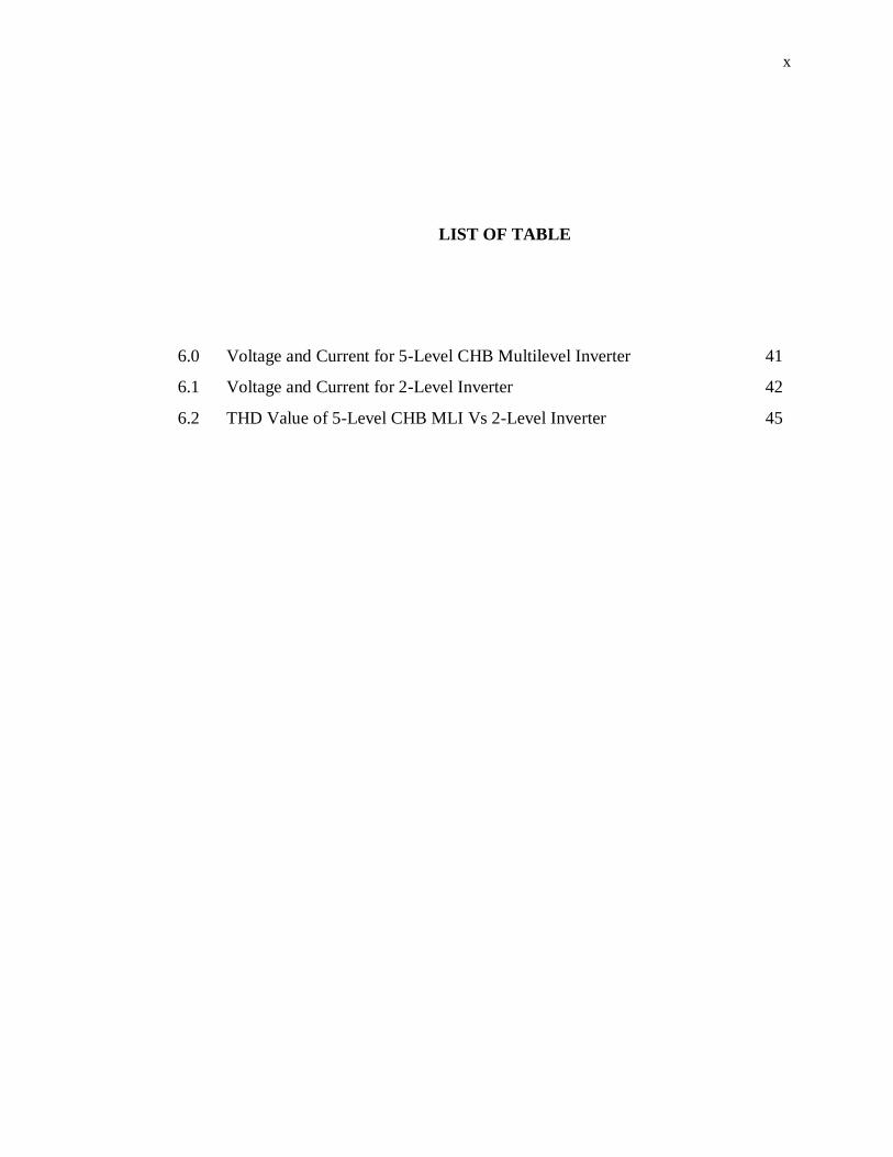
LIST OF TABLE
6.0 Voltage and Current for 5-Level CHB Multilevel Inverter 41
6.1 Voltage and Current for 2-Level Inverter 42
6.2 THD Value of 5-Level CHB MLI Vs 2-Level Inverter 45
xi
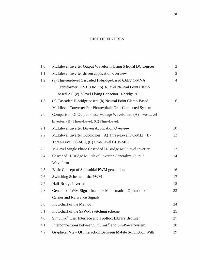
LIST OF FIGURES
1.0 Multilevel Inverter Output Waveform Using 5 Equal DC sources 2
1.1 Multilevel Inverter driven application overview 3
1.2 (a) Thirteen-level Cascaded H-bridge-based 6.6kV 1-MVA
Transformer STSTCOM. (b) 3-Level Neutral Point Clamp
based AF. (c) 7-level Flying Capacitor H-bridge AF.
4
1.3
2.0
(a) Cascaded H-bridge based. (b) Neutral Point Clamp Based
Multilevel Converter For Photovoltaic Grid-Connected System
Comparison Of Output Phase Voltage Waveforms: (A) Two-Level
Inverter, (B) Three-Level, (C) Nine-Level.
6
2.1 Multilevel Inverter Driven Application Overview 10
2.2 Multilevel Inverter Topologies: (A) Three-Level DC-MLI, (B)
Three-Level FC-MLI, (C) Five-Level CHB-MLI
12
2.3 M-Level Single Phase Cascaded H-Bridge Multilevel Inverter 13
2.4 Cascaded H-Bridge Multilevel Inverter Generalize Output
Waveform
14
2.5 Basic Concept of Sinusoidal PWM generation 16
2.6 Switching Scheme of the PWM 17
2.7 Half-Bridge Inverter 18
2.8 Generated PWM Signal from the Mathematical Operation of
Carrier and Reference Signals
23
3.0 Flowchart of the Method 24
3.1 Flowchart of the SPWM switching scheme 25
4.0 Simulink® User Interface and Toolbox Library Browser 27
4.1 Interconnections between Simulink® and SimPowerSystem 28
4.2 Graphical View Of Interaction Between M-File S-Function With 29
xii
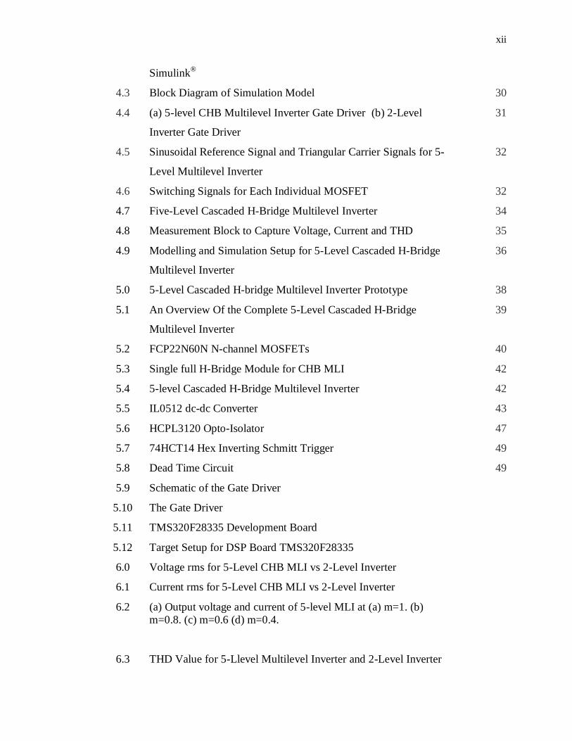
Simulink®
4.3 Block Diagram of Simulation Model 30
4.4 (a) 5-level CHB Multilevel Inverter Gate Driver (b) 2-Level
Inverter Gate Driver
31
4.5 Sinusoidal Reference Signal and Triangular Carrier Signals for 5-
Level Multilevel Inverter
32
4.6 Switching Signals for Each Individual MOSFET 32
4.7 Five-Level Cascaded H-Bridge Multilevel Inverter 34
4.8 Measurement Block to Capture Voltage, Current and THD 35
4.9 Modelling and Simulation Setup for 5-Level Cascaded H-Bridge
Multilevel Inverter
36
5.0 5-Level Cascaded H-bridge Multilevel Inverter Prototype 38
5.1 An Overview Of the Complete 5-Level Cascaded H-Bridge
Multilevel Inverter
39
5.2 FCP22N60N N-channel MOSFETs 40
5.3 Single full H-Bridge Module for CHB MLI 42
5.4 5-level Cascaded H-Bridge Multilevel Inverter 42
5.5 IL0512 dc-dc Converter 43
5.6 HCPL3120 Opto-Isolator 47
5.7 74HCT14 Hex Inverting Schmitt Trigger 49
5.8 Dead Time Circuit 49
5.9 Schematic of the Gate Driver
5.10 The Gate Driver
5.11 TMS320F28335 Development Board
5.12 Target Setup for DSP Board TMS320F28335
6.0 Voltage rms for 5-Level CHB MLI vs 2-Level Inverter
6.1 Current rms for 5-Level CHB MLI vs 2-Level Inverter
6.2 (a) Output voltage and current of 5-level MLI at (a) m=1. (b) m=0.8. (c) m=0.6 (d) m=0.4.
6.3 THD Value for 5-Llevel Multilevel Inverter and 2-Level Inverter

xiii
B.1 5-level Cascaded H-bridge Multilevel Inverter Output Waveform. Green Line is the Filtered Waveform.
xiv
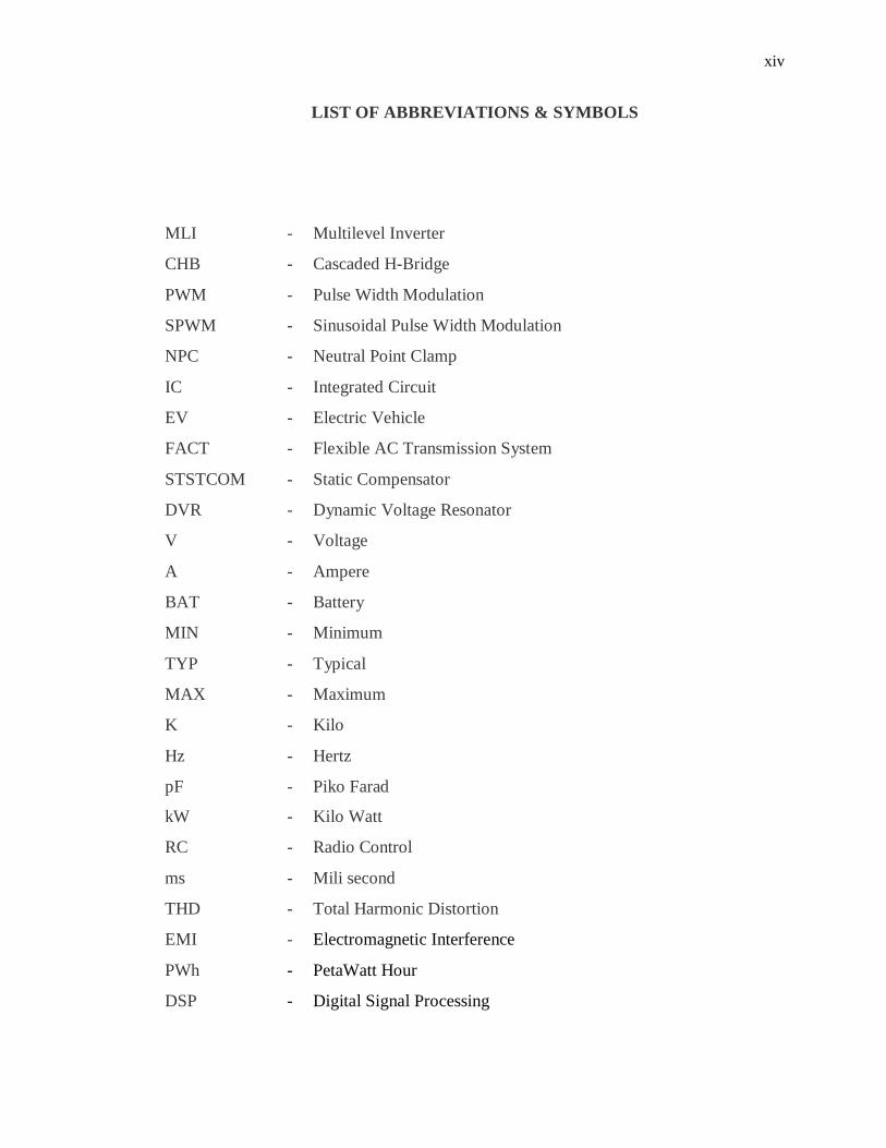
LIST OF ABBREVIATIONS & SYMBOLS
MLI - Multilevel Inverter
CHB - Cascaded H-Bridge
PWM - Pulse Width Modulation
SPWM - Sinusoidal Pulse Width Modulation
NPC - Neutral Point Clamp
IC - Integrated Circuit
EV - Electric Vehicle
FACT - Flexible AC Transmission System
STSTCOM - Static Compensator
DVR - Dynamic Voltage Resonator
V - Voltage
A - Ampere
BAT - Battery
MIN - Minimum
TYP - Typical
MAX - Maximum
K - Kilo
Hz - Hertz
pF
kW
- Piko Farad
- Kilo Watt
RC - Radio Control
ms - Mili second
THD - Total Harmonic Distortion
EMI - Electromagnetic Interference
PWh - PetaWatt Hour
DSP - Digital Signal Processing
xv
AC - Alternating Current
DC - Direct Current
VSI - Voltage Source Inverter
CSI - Current Source Inverter
HVDC - High Voltage Direct Current
UPS - Uninterruptable Power Supplies
NPC - Neutral Point Clamp
FC - Flying Capacitor
MOB - Multi-output Boost
SVM - Space Vector Modulation
THIPWM - Third Harmonic Injection Pulse Width Modulation
FPGA - Field Programmable Grid Array

xvi
LIST OF APPENDICS
APPENDIX TITTLE PAGE
A Program Source Code 52
B Figure of CHB-MLI 55
C Data Sheet 56
1
CHAPTER 1
INTRODUCTION
1.0 Chapter Overview
The following chapter serves several purposes. Section 1.1 provides a brief
discussion of the research project presented in this thesis. General idea of multilevel
inverter is presented in section 1.2. Section 1.3 discusses some of the application of
multilevel inverter in real situation. Merit and demerits of multilevel are briefly
discussed in section 1.4. A comparison of multilevel fundamental switching over
PWM switching is discussed in section 1.5. In section 1.6, problem statements of the
research is presented and followed by objectives of research and its scope of work in
section 1.7 and 1.8 respectively. Thesis outline and chapter summary are concluded
in section 1.9.
1.1 The Work
In this research, a multilevel inverter with an equal direct current (DC) sources is
studied and developed. The common switching method is used to control the power
transistor.
The implementation of Pulse Width Modulation (PWM)
method as a control technique was modeled and simulated in five levels and two
levels scheme to see the different properties of harmonics and power output of the
inverters in an ideal environment. The resultant form the simulation is then
compared with an actual hardware and experiment setup.
2
Using the idea of mathematical operation of sinusoidal signal and triangle
signals, the algorithm is developed to get switching pulses for the inverters. This
algorithm is considered as a core element in the development of the inverter model
and the experimental hardware.
1.2 Multilevel Converter
Three main multilevel converter topologies which have been mostly applied in
engineering application are known as the cascaded h-bridge converter with separated
dc sources, the diode clamp and the flying capacitor and
Here, it seems important to discuss the different between the terms
‘multilevel converters’ and ‘multilevel inverter’. The word ‘multilevel converter’
refers to the converter itself. The implication of the term reflects that the power can
flow in one of two directions. Power which flow from the ac side to the dc side of
the multilevel converter is operated in rectification mode. Vice-versa, the power also
can flow from the dc side to the ac side of the converter. This mode is called as
inverting mode of operation. The ‘multilevel inverter’ term basically is a ‘multilevel
converter’ that uses the inverting mode of operation.
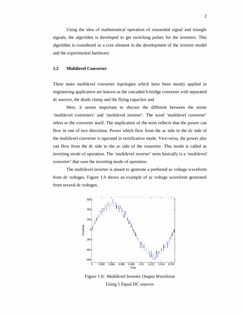
The multilevel inverter is meant to generate a preferred ac voltage waveform
from dc voltages. Figure 1.0 shows an example of ac voltage waveform generated
from several dc voltages.
Figure 1.0: Multilevel Inverter Output Waveform
Using 5 Equal DC sources
3
In above figure, five 120 V dc source produce a pulse waveform with a peak-
to-peak voltage of 1200V. Here, the multilevel inverter produces a fair
approximation to a sinusoidal waveform. This approximation will get better and
better once the amount of dc sources increase. Ideally, once the number of dc
sources reach infinity, the pulse waveform will become a pure desired sinusoidal.
Considering a switching scheme, there are many techniques has been develop
to be implemented on a multilevel inverter. For example, Sinusoidal PWM, Space
Vector PWM, and Selective Harmonic Elimination PWM.
One of the merits of using multilevel inverter is the better total harmonic
distortion over the well-known conventional two level inverters. This can be proven
by undergo a simulation and experimental exercise.
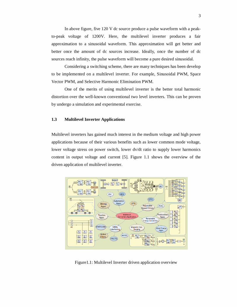
1.3 Multilevel Inverter Applications
Multilevel inverters has gained much interest in the medium voltage and high power
applications because of their various benefits such as lower common mode voltage,
lower voltage stress on power switch, lower dv/dt ratio to supply lower harmonics
content in output voltage and current [5]. Figure 1.1 shows the overview of the
driven application of multilevel inverter.
Figure1.1: Multilevel Inverter driven application overview
4
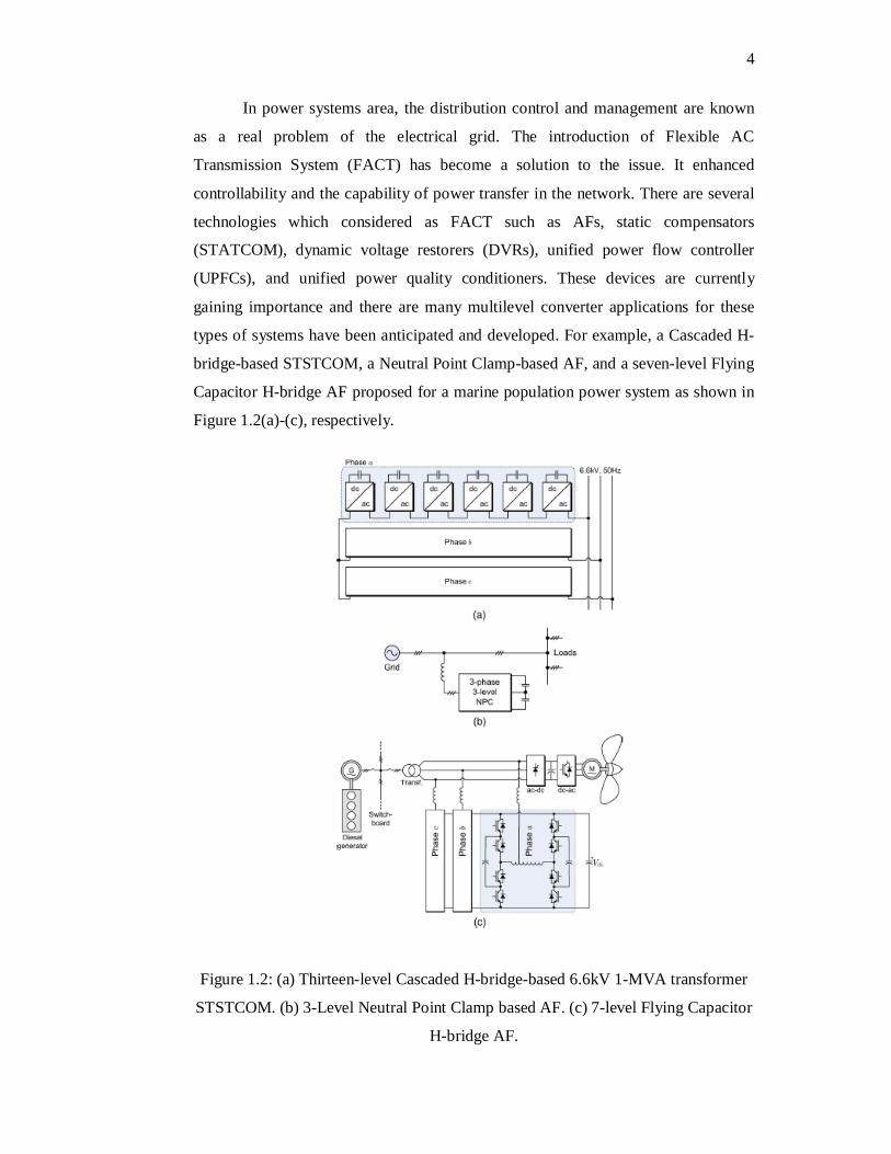
In power systems area, the distribution control and management are known
as a real problem of the electrical grid. The introduction of Flexible AC
Transmission System (FACT) has become a solution to the issue. It enhanced
controllability and the capability of power transfer in the network. There are several
technologies which considered as FACT such as AFs, static compensators
(STATCOM), dynamic voltage restorers (DVRs), unified power flow controller
(UPFCs), and unified power quality conditioners. These devices are currently
gaining importance and there are many multilevel converter applications for these
types of systems have been anticipated and developed. For example, a Cascaded H-
bridge-based STSTCOM, a Neutral Point Clamp-based AF, and a seven-level Flying
Capacitor H-bridge AF proposed for a marine population power system as shown in
Figure 1.2(a)-(c), respectively.
Figure 1.2: (a) Thirteen-level Cascaded H-bridge-based 6.6kV 1-MVA transformer
STSTCOM. (b) 3-Level Neutral Point Clamp based AF. (c) 7-level Flying Capacitor
H-bridge AF.
5
Environmental concerns are increasing recently. People are now talking
about carbon emission to the air by internal combustion engine vehicles. This lead to
the massive research and development to a new eco-friendly vehicle like electric
vehicles (EV) and hybrid type vehicles. Although they are experiencing great
development recently, however, multilevel inverters/converters have not played a
key-role in this area due to the fact that they are out of the range of high-power.
However, due to its capability in having a superior power quality, better efficiency,
and significantly benefit from independent dc source such as batteries have motivate
numerous researchers to propose some interesting concept toward multilevel inverter
applications in EVs and hybrid vehicles in automotive applications.
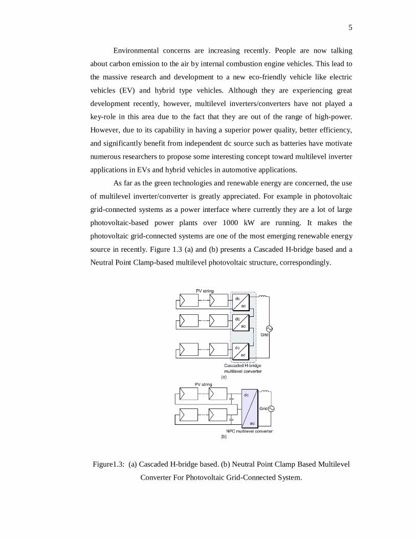
As far as the green technologies and renewable energy are concerned, the use
of multilevel inverter/converter is greatly appreciated. For example in photovoltaic
grid-connected systems as a power interface where currently they are a lot of large
photovoltaic-based power plants over 1000 kW are running. It makes the
photovoltaic grid-connected systems are one of the most emerging renewable energy
source in recently. Figure 1.3 (a) and (b) presents a Cascaded H-bridge based and a
Neutral Point Clamp-based multilevel photovoltaic structure, correspondingly.
Figure1.3: (a) Cascaded H-bridge based. (b) Neutral Point Clamp Based Multilevel
Converter For Photovoltaic Grid-Connected System.
6
1.4 Merit and Demerit of Multilevel Inverter
Obviously, in recent years multilevel inverter has gained an attention from many
areas due to its advantages over the conventional inverters. The ability of the
multilevel inverter to utilize a large number of dc sources is one of the merits that it
holds. This makes multilevel inverters able to generate high voltages and thus high
power ratings. Due to this, the use of bulky and expensive transformers to produces
high voltages with conventional 12, 24 and 48-pulse inverter can be abandoned.
Another advantage of multilevel inverter is that it has a reduced Total
Harmonic Distortion (THD) with low switching frequencies. Furthermore, due to its
lower voltage steps, the value of EMI is lesser and because of its capability to utilize
multiple levels on the dc bus, the multilevel inverters able to trim down the voltage
stress on each power devices. Additionally, multilevel inverters have higher
efficiency because the devices can be switched at low frequency.
Nevertheless, there is still a pitfalls on everything created in this world
including multilevel inverter. One of the demerits of multilevel inverters is the
isolated power supplies required for each one of the multiconverter. Furthermore,
number of components is increased in multilevel inverter compared to traditional
inverters. The idea of having larger number of components also means the
probability of a device failure will increase.
1.5 The Switching
There are many ways and techniques have been developed to control multilevel
inverter switching, from the very basic fundamental switching up to the most
advance space vector pulse width modulation switching scheme. But, the most
famous and applied by industries out there is the PWM switching control scheme.
PWM switching control scheme comes with advantages over the traditional
multilevel fundamental switching scheme.
One benefit of PWM methods employing much higher switching frequencies
concerns harmonics. The harmonics filtering exercise is much easier and cheaper
due to the fact that the undesirable harmonics occur at much higher switching
frequencies. Also, the produced harmonics might be above the bandwidth of some
actual system. This means that there is no power dissipation caused by the
7
harmonics. On the contrary, multilevel fundamental switching scheme creates
harmonics at lower switching frequencies and this increased the complexity of the
filtering activity.
1.6 Problem Statement
Ever since the industrial revolution in 1800, the demand for energy is increased
dramatically, especially in developing countries in-line with the economy growth.
Modern industrial machineries, electric vehicles, home appliances and public
healthcare contribute to the high demand of energy. The recent policies situation in
World Energy Outlook 2012 (WEO 12) revealed that “several fundamental trends
persist: energy demand and CO2 emission rise even higher; energy market dynamics
are increasingly determine by emerging economies; fossil fuels remain the dominant
source; and providing universal energy access to the world's poor countries
continues to be an elusive goal”.
WEO 12 highlights that electricity generation increases form 21.5 PWh in
2010 to 36.6 PWh in 2035, with average price increase of 15% in real terms. As the
nuclear capacity projection reduced for 2035, the renewable are likely to become the
world’s second largest source of power generation by 2015 with electricity
generation share increase from 20% in 2010 to 31% by 2035. This is true as the
researches are aggressively looking into other environmental friendly source even
before the Japan nuclear incident in 2011. A renewable energy technology has
become a prime agenda which mainly focusing on wind, solar and energy efficiency
technologies in order to reduce increasing demands.
As far as the solar power is concerned, there is still a lot of work has to be
done to bring the technology become a major player in electricity generation. Not
only the efficiency of the PV cell, but also related instruments required by the system
as the highest PV efficiency now is just around 40%. This will justify how important
the other instrument to be at best efficiency to achieve optimum energy from the sun.
One of the important components in the system is the inverter which
converts the DC energy stored in the battery banks to AC energy which will then
used by consumer or connected to power grid. As the current trend required cleaner
power source, higher output power, less losses and almost free harmonics, people are
looking forward for better inverter. Thus, a conventional single level inverter is no
8
more relevant to cope with the current trend. Nowadays, industries, researches are
focusing to come out with inverter that can overcome the above mentioned issues.
As a result a multilevel inverter is created and first published by Nabae in 1980s.
1.7 The Objectives
There are three objective have been set for this work to be achieved at the end of the
activities.
To simulate the modelled Cascaded H-Bridge Multilevel Inverter (CHB-
MLI) performance with the implementation of Sinusoidal PWM control
technique
To implement DSP based Sinusoidal PWM controller on develop CHB-MLI
hardware.
To analyse the multilevel inverter performance in term of THD, output
voltage level between multilevel inverter and conventional h-bridge inverter.
1.8 Project Scope
The work is focusing on the development of a single phase five-level multilevel
inverter only. The developed multilevel inverter is based on the Cascaded H-bridge
Multilevel Inverter (CHB-MLI) topology and the switching is controlled by the
implementation of sinusoidal pulse width modulation scheme (SPWM). In-term of
analysis, the works are limited to the comparison of total harmonic distortion
between conventional inverter and multilevel inverter and its output voltage.
1.9 Thesis outline
In chapter 1, several topics were discussed. The brief summary of the work to be
presented in this thesis was first described. The introductory of basic knowledge of
multilevel converter was discussed. Also, the typical applications of multilevel
inverter were also given. The discussion came along with the merits and demerits of
using multilevel inverter as well as the switching method. Furthermore, problem
statement, project scope and its objective were also discussed in this chapter.
9
Chapter 2, discussions were focus on the inverter, multilevel inverter and also
the selected topology used in the project, the Cascaded H-bridge Multilevel Inverter.
This chapter also discussed in depth on sinusoidal pulse width modulation technique.
Previous work by other researchers also discussed here.
Methodologies that have been carried out to run this research were revealed
in Chapter 3. Four milestones were discussed.
To further discuss on modelling and simulation works, Chapter 4 provides
information of the works done. Induction on SimPowerSystem, S-function and
related blocks used in the modelling and simulation were discussed in this chapter.
Chapter 5 will discuss more on hardware development. The circuitries,
components and related items were presented here.
Results and analysis from the research were discussed in Chapter 6. The
discussions were mainly focused on voltage and current rms produced by the
multilevel inverter. Moreover, total harmonic distortion values come out from the
inverters were also compared and analysed.
Chapter 7 were basically concluded all the works and results obtained from
the research. Some suggestions for future improvement were also included in this
chapter.
10
CHAPTER 2
LITERATURE REVIEW
2.0 Chapter Overview
In this chapter, several topics on core theories behind the research will be discussed.
Section 2.1 provides information on the inverter and the Cascaded H-bridge
multilevel inverter which has been used in the research. Later, a control technique
sinusoidal pulse width modulation is discussed in section 2.2 in more details. In
section 2.3, researches that have been done previously by others which closely
related to this research are revealed and discussed.
2.1 The Inverter and Multilevel Inverter
2.1.1 The Inverter
A device that converts DC power into AC power at desired output voltage and
frequency is called an Inverter. Phase controlled converters when operated in the
inverter mode are called line commutated inverters. But line commutated inverters
require at the output terminals an existing AC supply which is used for their
commutation. This means that line commutated inverters cannot function as isolated
AC voltage sources or as variable frequency generators with DC power at the input.
Therefore, voltage level, frequency and waveform on the AC side of the line
commutated inverters cannot be changed. On the other hand, force commutated
inverters provide an independent AC output voltage of adjustable voltage and

11
adjustable frequency and have therefore much wider application. Based on their
operation the inverters can be broadly classified into
Voltage Source Inverters(VSI)
Current Source Inverters(CSI)
A voltage source inverter is one where the independently controlled ac
output is a voltage waveform. A current source inverter is one where the
independently controlled ac output is a current waveform. Some industrial
applications of inverters are for adjustable- speed ac drives, induction heating, stand
by air-craft power supplies, UPS uninterruptible power supplies) for computers,
HVDC transmission lines etc. An inverter changes DC voltage from batteries or
solar panels, into standard household AC voltage so that it can be used by common
tools and appliances. Essentially, it does the opposite of what a battery charger or
"converter" does. DC is usable for some small appliances, lights, and pumps, but not
much else. Some DC appliances are available, but with the exception of lights, fans
and pumps there is not a wide selection. Most other 12 volt items we have seen are
expensive and/or poorly made compared to their AC cousins. The most common
battery voltage inputs for inverters are 12, 24, and 48 volts DC - a few models also
available in other voltages. There is also a special line of inverters called a utility
intertie or grid tie, which does not usually use batteries - the solar panels or wind
generator feeds directly into the inverter and the inverter output is tied to the grid
power. The power produced is either sold back to the power company or (more
commonly) offsets a portion of the power used. These inverters usually require a
fairly high input voltage - 48 volts or more. Some, like the Sunny Boy, go up to 600
volts DC input.
2.1.2 The Multilevel Inverter
Among available inverter in today market, multilevel inverter comes with great
advantages. This is also true if a comparison done to a well-known two-level inverter
[2]. Basically these advantages are focused on improvements in the output signal
quality and a nominal power increase in the inverters. The term multilevel inverter
was first introduced back in 1981 by Nabae [3]. By increasing the numbers of levels
in the inverter, the output voltages have more steps generating a staircase waveform,
12
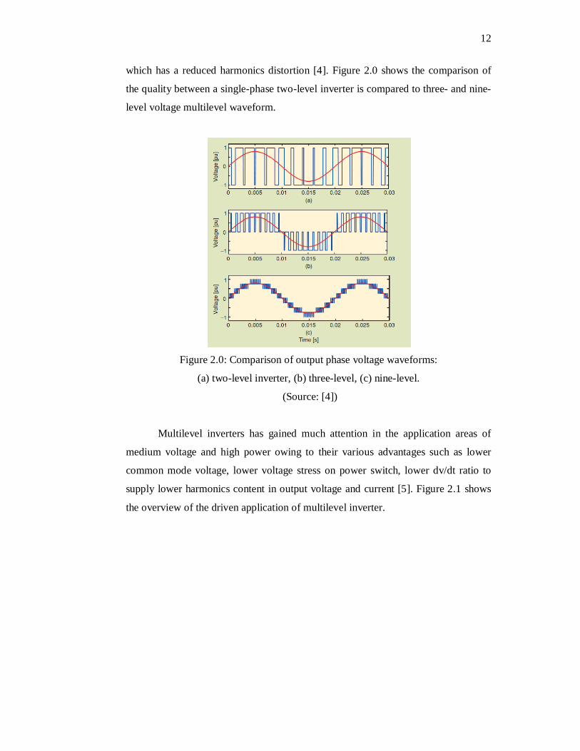
which has a reduced harmonics distortion [4]. Figure 2.0 shows the comparison of
the quality between a single-phase two-level inverter is compared to three- and nine-
level voltage multilevel waveform.
Figure 2.0: Comparison of output phase voltage waveforms:
(a) two-level inverter, (b) three-level, (c) nine-level.
(Source: [4])
Multilevel inverters has gained much attention in the application areas of
medium voltage and high power owing to their various advantages such as lower
common mode voltage, lower voltage stress on power switch, lower dv/dt ratio to
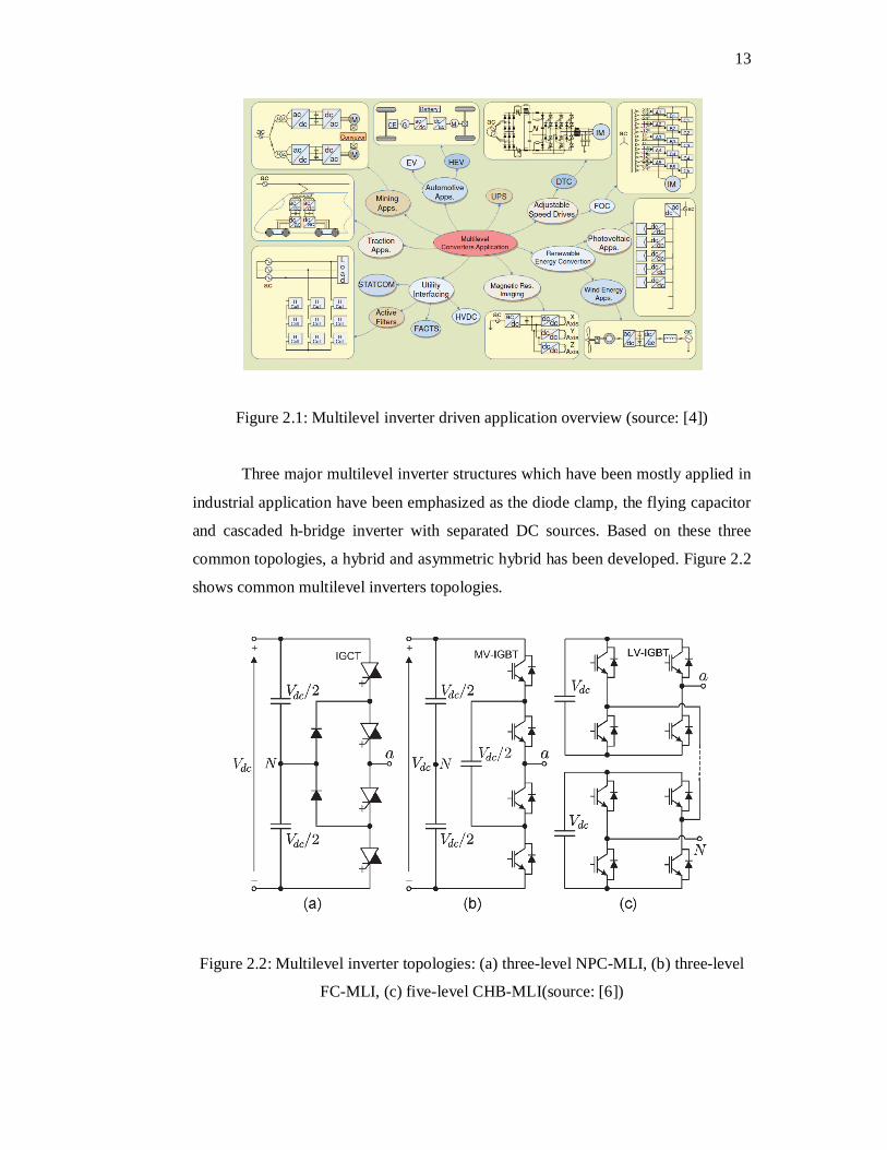
supply lower harmonics content in output voltage and current [5]. Figure 2.1 shows
the overview of the driven application of multilevel inverter.
13
Figure 2.1: Multilevel inverter driven application overview (source: [4])
Three major multilevel inverter structures which have been mostly applied in
industrial application have been emphasized as the diode clamp, the flying capacitor
and cascaded h-bridge inverter with separated DC sources. Based on these three
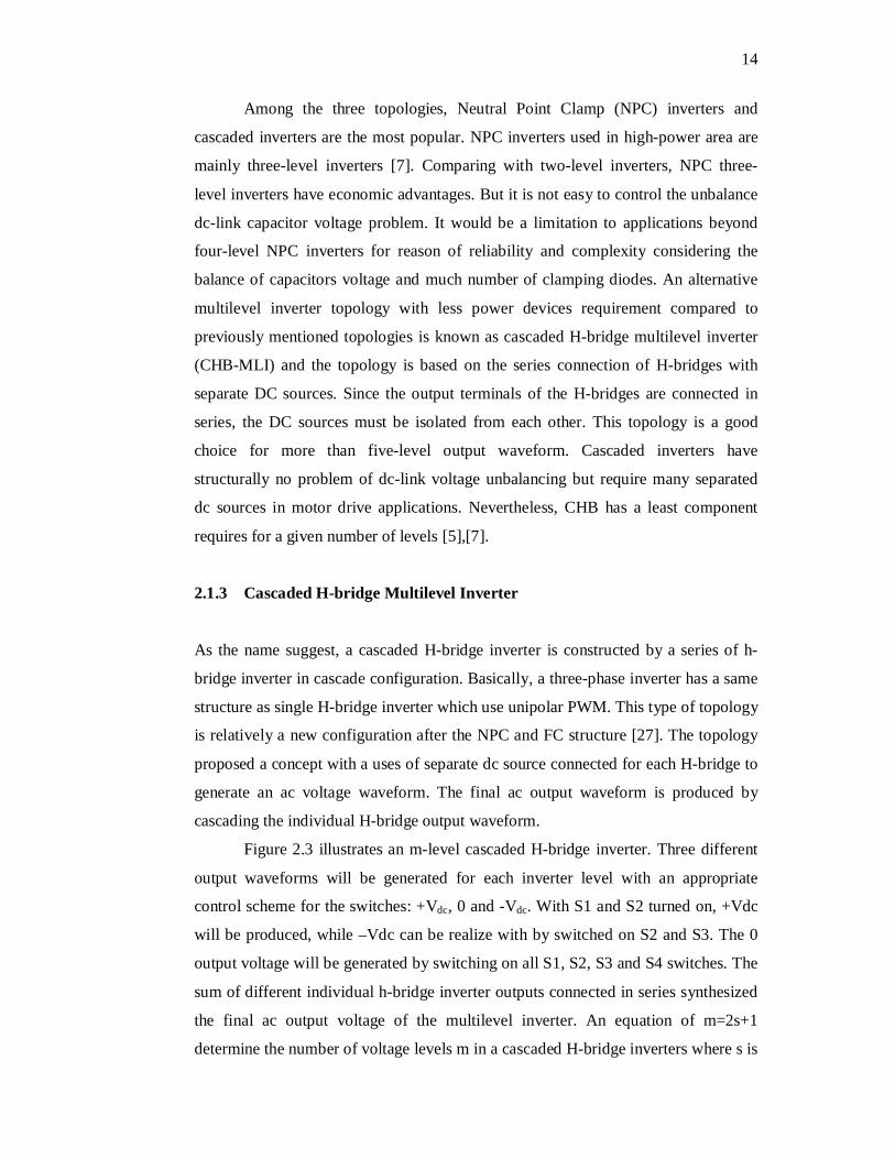
common topologies, a hybrid and asymmetric hybrid has been developed. Figure 2.2
shows common multilevel inverters topologies.
Figure 2.2: Multilevel inverter topologies: (a) three-level NPC-MLI, (b) three-level
FC-MLI, (c) five-level CHB-MLI(source: [6])
14
Among the three topologies, Neutral Point Clamp (NPC) inverters and
cascaded inverters are the most popular. NPC inverters used in high-power area are
mainly three-level inverters [7]. Comparing with two-level inverters, NPC three-
level inverters have economic advantages. But it is not easy to control the unbalance
dc-link capacitor voltage problem. It would be a limitation to applications beyond
four-level NPC inverters for reason of reliability and complexity considering the
balance of capacitors voltage and much number of clamping diodes. An alternative
multilevel inverter topology with less power devices requirement compared to
previously mentioned topologies is known as cascaded H-bridge multilevel inverter
(CHB-MLI) and the topology is based on the series connection of H-bridges with
separate DC sources. Since the output terminals of the H-bridges are connected in
series, the DC sources must be isolated from each other. This topology is a good
choice for more than five-level output waveform. Cascaded inverters have
structurally no problem of dc-link voltage unbalancing but require many separated
dc sources in motor drive applications. Nevertheless, CHB has a least component
requires for a given number of levels [5],[7].
2.1.3 Cascaded H-bridge Multilevel Inverter
As the name suggest, a cascaded H-bridge inverter is constructed by a series of h-
bridge inverter in cascade configuration. Basically, a three-phase inverter has a same
structure as single H-bridge inverter which use unipolar PWM. This type of topology
is relatively a new configuration after the NPC and FC structure [27]. The topology
proposed a concept with a uses of separate dc source connected for each H-bridge to
generate an ac voltage waveform. The final ac output waveform is produced by
cascading the individual H-bridge output waveform.
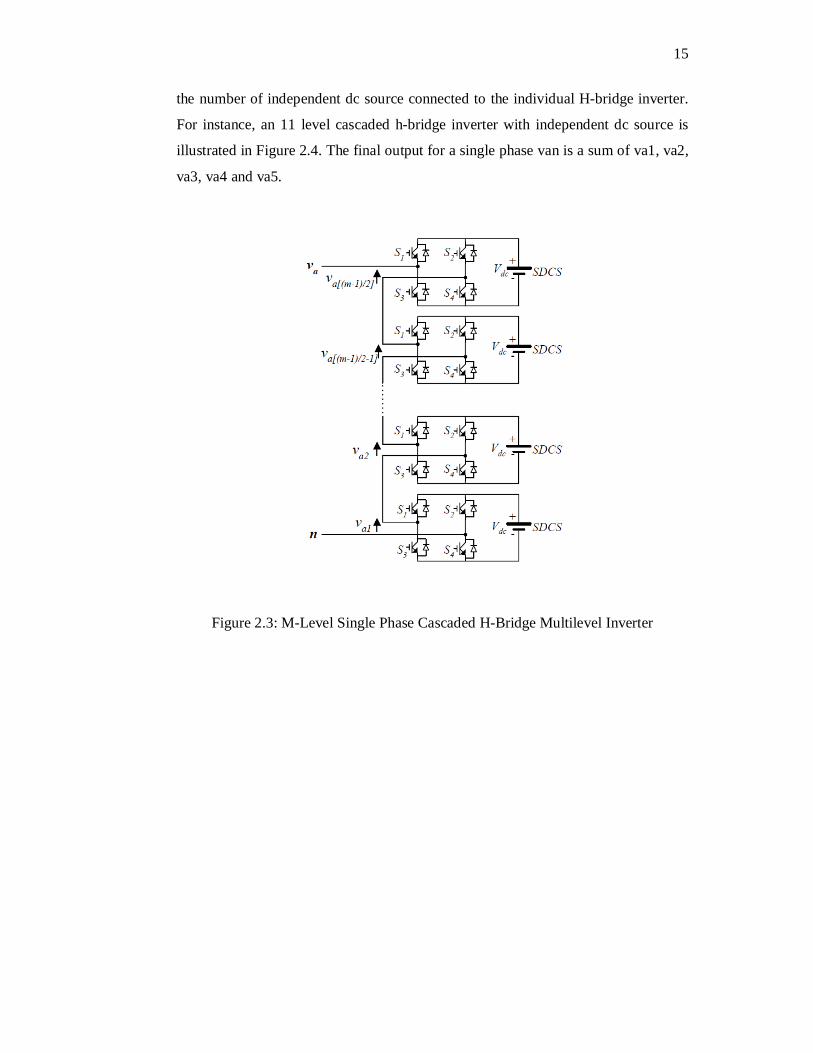
Figure 2.3 illustrates an m-level cascaded H-bridge inverter. Three different
output waveforms will be generated for each inverter level with an appropriate
control scheme for the switches: +Vdc, 0 and -Vdc. With S1 and S2 turned on, +Vdc
will be produced, while –Vdc can be realize with by switched on S2 and S3. The 0
output voltage will be generated by switching on all S1, S2, S3 and S4 switches. The
sum of different individual h-bridge inverter outputs connected in series synthesized
the final ac output voltage of the multilevel inverter. An equation of m=2s+1
determine the number of voltage levels m in a cascaded H-bridge inverters where s is
15
the number of independent dc source connected to the individual H-bridge inverter.
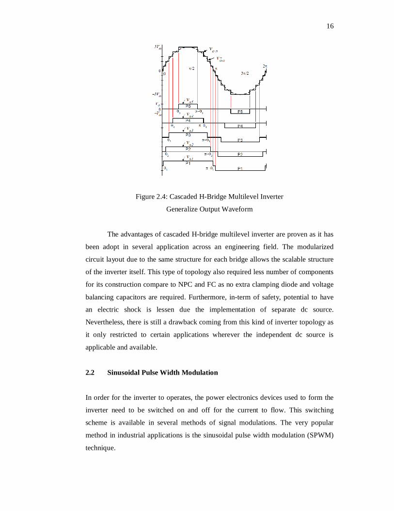
For instance, an 11 level cascaded h-bridge inverter with independent dc source is
illustrated in Figure 2.4. The final output for a single phase van is a sum of va1, va2,
va3, va4 and va5.
Figure 2.3: M-Level Single Phase Cascaded H-Bridge Multilevel Inverter
16
Figure 2.4: Cascaded H-Bridge Multilevel Inverter
Generalize Output Waveform
The advantages of cascaded H-bridge multilevel inverter are proven as it has
been adopt in several application across an engineering field. The modularized
circuit layout due to the same structure for each bridge allows the scalable structure
of the inverter itself. This type of topology also required less number of components
for its construction compare to NPC and FC as no extra clamping diode and voltage
balancing capacitors are required. Furthermore, in-term of safety, potential to have
an electric shock is lessen due the implementation of separate dc source.
Nevertheless, there is still a drawback coming from this kind of inverter topology as
it only restricted to certain applications wherever the independent dc source is
applicable and available.
2.2 Sinusoidal Pulse Width Modulation
In order for the inverter to operates, the power electronics devices used to form the
inverter need to be switched on and off for the current to flow. This switching
scheme is available in several methods of signal modulations. The very popular
method in industrial applications is the sinusoidal pulse width modulation (SPWM)
technique.
17
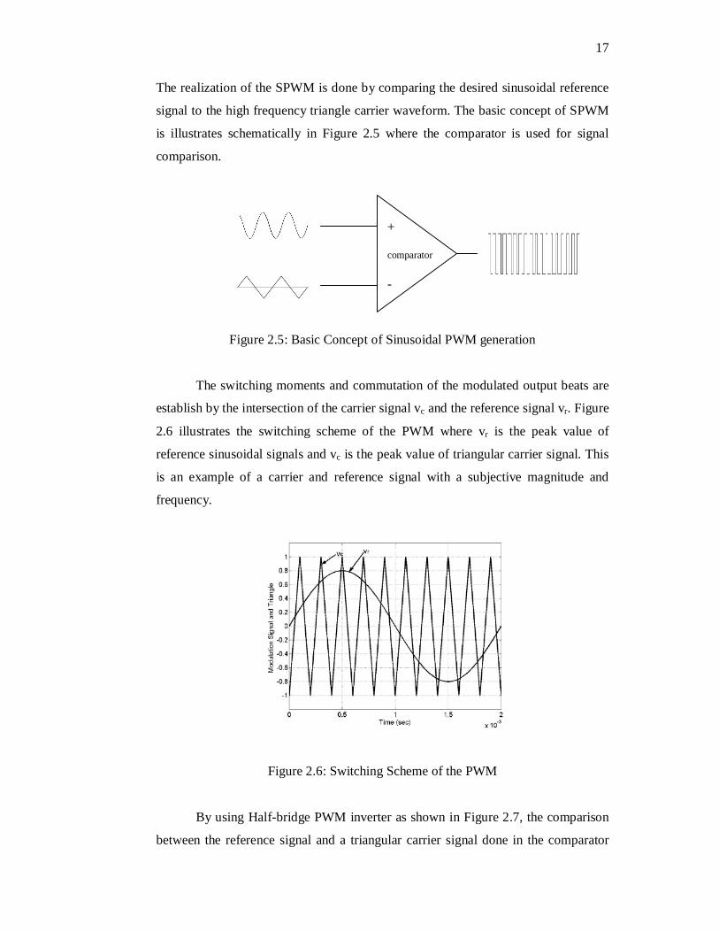
The realization of the SPWM is done by comparing the desired sinusoidal reference
signal to the high frequency triangle carrier waveform. The basic concept of SPWM
is illustrates schematically in Figure 2.5 where the comparator is used for signal
comparison.
Figure 2.5: Basic Concept of Sinusoidal PWM generation
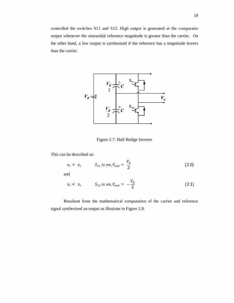
The switching moments and commutation of the modulated output beats are
establish by the intersection of the carrier signal vc and the reference signal vr. Figure
2.6 illustrates the switching scheme of the PWM where vr is the peak value of
reference sinusoidal signals and vc is the peak value of triangular carrier signal. This
is an example of a carrier and reference signal with a subjective magnitude and
frequency.
Figure 2.6: Switching Scheme of the PWM
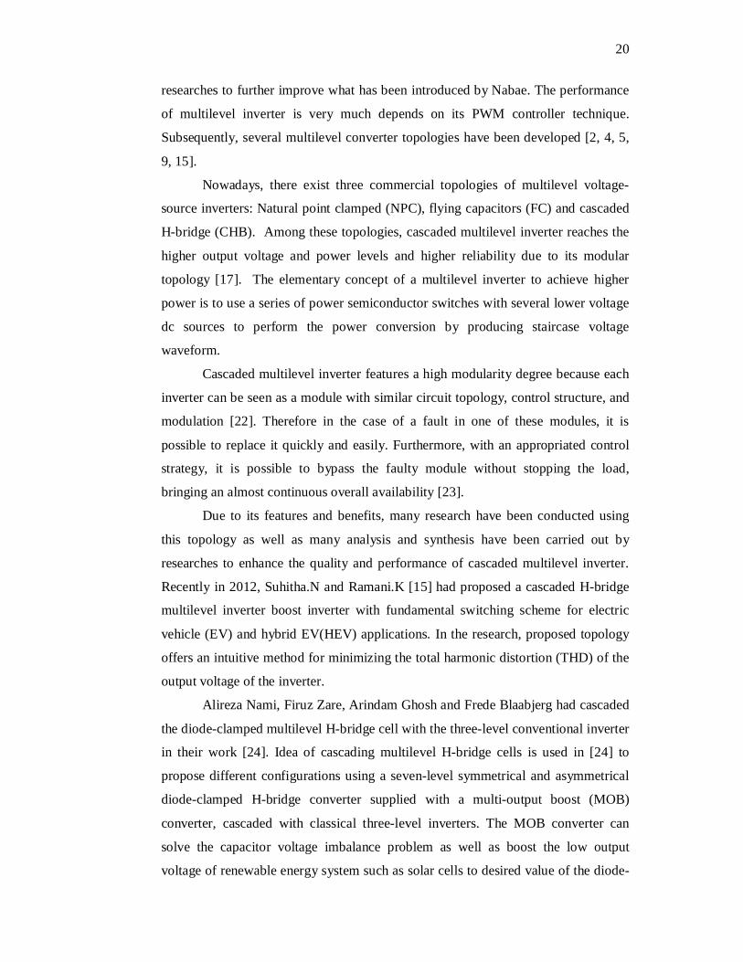
By using Half-bridge PWM inverter as shown in Figure 2.7, the comparison
between the reference signal and a triangular carrier signal done in the comparator
+ comparator -
18
controlled the switches S11 and S12. High output is generated at the comparator
output whenever the sinusoidal reference magnitude is greater than the carrier. On
the other hand, a low output is synthesized if the reference has a magnitude lowers
than the carrier.
Figure 2.7: Half-Bridge Inverter
This can be described as:
푣 > 푣 푆 푖푠표푛,푉 = 푉2 (2.0)
and
푣 < 푣 푆 푖푠표푛,푉 = −푉2 (2.1)
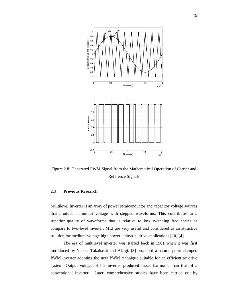
Resultant from the mathematical computation of the carrier and reference
signal synthesized an output as illustrate in Figure 2.8.
19
Figure 2.8: Generated PWM Signal from the Mathematical Operation of Carrier and
Reference Signals
2.3 Previous Research
Multilevel Inverter is an array of power semiconductor and capacitor voltage sources
that produce an output voltage with stepped waveforms. This contributes to a
superior quality of waveforms that is relative to low switching frequencies as
compare to two-level inverter. MLI are very useful and considered as an attractive
solution for medium-voltage high power industrial drive applications [10],[4].
The era of multilevel inverter was started back in 1981 when it was first
introduced by Nabae, Takahashi and Akagi. [3] proposed a natural point clamped
PWM inverter adopting the new PWM technique suitable for an efficient ac drive
system. Output voltage of the inverter produced lesser harmonic than that of a
conventional inverter. Later, comprehensive studies have been carried out by
20
researches to further improve what has been introduced by Nabae. The performance
of multilevel inverter is very much depends on its PWM controller technique.
Subsequently, several multilevel converter topologies have been developed [2, 4, 5,
9, 15].
Nowadays, there exist three commercial topologies of multilevel voltage-
source inverters: Natural point clamped (NPC), flying capacitors (FC) and cascaded
H-bridge (CHB). Among these topologies, cascaded multilevel inverter reaches the
higher output voltage and power levels and higher reliability due to its modular
topology [17]. The elementary concept of a multilevel inverter to achieve higher
power is to use a series of power semiconductor switches with several lower voltage
dc sources to perform the power conversion by producing staircase voltage
waveform.
Cascaded multilevel inverter features a high modularity degree because each
inverter can be seen as a module with similar circuit topology, control structure, and
modulation [22]. Therefore in the case of a fault in one of these modules, it is
possible to replace it quickly and easily. Furthermore, with an appropriated control
strategy, it is possible to bypass the faulty module without stopping the load,
bringing an almost continuous overall availability [23].
Due to its features and benefits, many research have been conducted using
this topology as well as many analysis and synthesis have been carried out by
researches to enhance the quality and performance of cascaded multilevel inverter.
Recently in 2012, Suhitha.N and Ramani.K [15] had proposed a cascaded H-bridge
multilevel inverter boost inverter with fundamental switching scheme for electric
vehicle (EV) and hybrid EV(HEV) applications. In the research, proposed topology
offers an intuitive method for minimizing the total harmonic distortion (THD) of the
output voltage of the inverter.
Alireza Nami, Firuz Zare, Arindam Ghosh and Frede Blaabjerg had cascaded
the diode-clamped multilevel H-bridge cell with the three-level conventional inverter
in their work [24]. Idea of cascading multilevel H-bridge cells is used in [24] to
propose different configurations using a seven-level symmetrical and asymmetrical
diode-clamped H-bridge converter supplied with a multi-output boost (MOB)
converter, cascaded with classical three-level inverters. The MOB converter can
solve the capacitor voltage imbalance problem as well as boost the low output
voltage of renewable energy system such as solar cells to desired value of the diode-
21
clamp dc link voltage. From this, a nineteen output voltage levels performance was
achieved, which has more voltage levels as well as lower voltage, and current THD
rather than using a symmetrical diode-clamped inverter with the same configuration
and equivalent number of power component.
Due to the fact that nowadays most of the modern industrial devices are
based on electronic devices, they are very sensitive to disturbance and less tolerant to
power quality problems. In 2011, N.Chellammal, K.N.V Prasad, S.S Dash, Y.S Anil
Kumar and A.Murali Krishna had done a performance analysis of three phase
cascaded H-bridge multilevel inverter for under voltage and over voltage conditions
[25]. The work involved a design of closed loop control system using PI controller
in order to maintain load voltage constant for under voltage and over voltage
conditions. The triggering pulses to cascaded H-bridge multilevel inverter is given
using multi carrier phase shift technique.
In the researches of multilevel inverters, its corresponding PWM control
strategies are one of the research hot points. Therefore several works were carried
out to compare and analyze on different type or technique to control the switching of
the multilevel inverters. V.Kumar Chinnaiyan, Jovitha Jerome, J.Karpagam and
T.Suresh had proposed a comparison between different switching strategies for
cascaded multilevel inverters, based on sinusoidal pulse width modulation (SPWM)
and space vector modulation (SVM) [8]. The work is based on simulation of 5-level
cascaded multilevel inverter using Matlab and Simulink® software. The research
reveal that the gain of the inverter is increased when using THIPWM, but a third
order harmonic is present in the phase voltage, which causes serious problems when
the neutral point is grounded. What have been done by a group of researchers from
Greater India also carried out by Berrezzek Farid and Omeiri Amar. In [26], they are
using new types of modulation in order to increase the output voltages of the inverter
for the same continuous voltage supply. The so-called new modulation technique
involves SPWM, THIPWM and SVPWM. The comparison studies show reveals that
SVPWM and THIPWM technique give a better performance compared to
conventional SPWM method.
Based on above review a conclusion on the advantages of multilevel inverter
are clear. Several researches reveal that the use of CHB-MLI has advantages over
other multilevel inverter topologies and obviously better when the higher degree of

22
levels in introduced. With the implementation of cascaded H-bridge topology and
SPWM method, it is believe that a better and efficient inverter shall be produced.
23
CHAPTER 3
METHODOLOGY
3.0 Chapter Overview
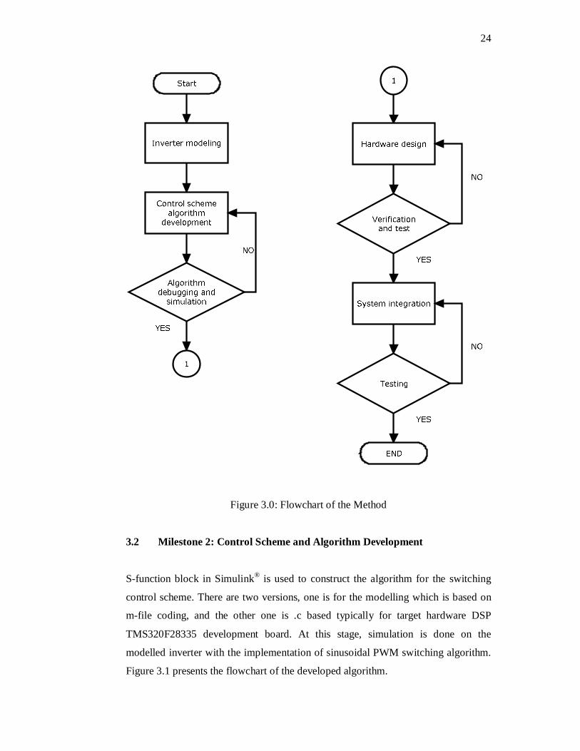
Milestones for the project completion are discussed in this chapter. Figure 3.0
illustrates the project methodology flowchart. Regardless of the literature, the
methodology involves modelling, simulation, hardware development and
experimental work.
The diagram in Figure 3.0 clarifies that the methodology is mainly divided
into two main tasks; the modelling and the hardware development/experimental. To
make it more specific, there are divided into four milestones as per section 3.1 to
section 3.4.
3.1 Milestone 1: Inverter modelling
Several topologies has been studied and based on the literature review, cascaded h-
bridge has a several advantages compared to others. With Simulink® / Matlab, 5-
level multilevel inverter and single level h-bridge inverter were modelled.
SimPowerSystem toolbox, signal processing toolbox and s-function block are
involves for the modelling.
24
Figure 3.0: Flowchart of the Method
3.2 Milestone 2: Control Scheme and Algorithm Development
S-function block in Simulink® is used to construct the algorithm for the switching
control scheme. There are two versions, one is for the modelling which is based on
m-file coding, and the other one is .c based typically for target hardware DSP
TMS320F28335 development board. At this stage, simulation is done on the
modelled inverter with the implementation of sinusoidal PWM switching algorithm.
Figure 3.1 presents the flowchart of the developed algorithm.
49
REFERENCES
[1] K. V. Kumar, P. A. Michael, J. P. John, S. S. Kumar, “Simulation and
comparison of spwm and svpwm control for three phase inverter,” in
APRN journal of Eng. And App. Sci., vol. 5, no. 7, pp. 61-74, jul. 2010.
[2] Jose Rodriguez, J. S. Lai, F. Z. Peng, “multilevel Inverter: A survey of
topologies, control, and applications,” in IEEE Trans. Ind. Elect. , vol. 49,
no 4, pp.724-738, aug. 2002.
[3] A.Nabae, I. Takahashi, and H. Akagi, “A new neutral-point clamped pwm
inverter,” in IEEE Trans. Ind. Appl., vol. IA-I7, no.5,pp.518-523, sep./oct.
1981
[4] Leopoldo G, Jose Rodriguez, Jose I. Leon, Samir Kouro, Ramon Portillo,
Maria A.M. Prats, “The age of multilevel converters arrives,” in IEEE
Industrial Electronics Megazine, June. 2008.
[5] Ilhami Colak, Ersan Kabalci, Ramazan Bayindir, “Review of multilevel
voltage inverter topologies and control schemes,” in Energy Conversion
And Management 52(2011) 1114-1128, Sep. 2010.
[6] S.Kuoro, M.Malinowski, K.Gopakumar, J.Pou, L.G.Franquelo, B.Wu,
J.Rodriguez, M.A.Perez, J.I.Leon, “ Recent Advance & Industrial
Applications of Multilevel Converter”, in IEEE Trans. On Industrial
Electronic, vol.57,no.8,aug 2010, pp.2553-2580.
[7] S. X. Tao, W. F. Jiang, S. Li, “A new multilevel space vector pwm
technique for h-bridge cascaded inverter,” in 2007 second IEEE Conf. On
Ind. Elec. And Appl., pp.2427 -2430
[8] V.Kumar Chinnaiyan, J.Jerome, J.Karpagam, T.Suresh, “Control
Techniques for Multilevel Voltage Source Inverter”, in the 8th
International Power Engineering Conference(PEC 2007)
[9] Surin Khomfoi, Leon M. Tolbert, “Chapter 31 Multilevel Power
Converter”, book chapter, The university of Tennesse.
50
[10] A. K. Gupta, A. M. Khambadkone, “A general space vector pwm
algorithm for multilevel inverter, including operation in overmodulation
range,” in IEEE Trans. Pow. Elect. , vol. 22, no. 2,pp. 517-526, mar. 2007.
[11] Anish. T, M. R. Baiju, “SVPWM Controller for multilevel inverter,” in
10th Conference on Technological Trends (NCTT09) pp. 218-223, nov.
2009,
[12] P. S. Kumar, J. Amarnath, S. V. L. Narasimham, “An effective space
vector pwm method for multilevel inverter based on two level inverter,” in
Int. Journal of Comp. And Elec. Eng., vol. 2, no. 2, pp. 243-250, apr.
2010.
[13] Ilhami Colak, Ramazan Bayindir, Ersan Kabalci, “ A Modified Harmonic
Mitigation Analysis Using Third Harmonic Injection PWM in Multilevel
Inverter Control”, in 14th International Power Electronic and Motion
Control Conference, EPE-PEMC2010, T2.215-T2.220.
[14] M.A.A Younis, N.A.Rahim, S.Mekhilef, “Harmonic Reduction in Three
Phase parallel Connected Inverter”, in World Academy of Science,
Engineering and Technology 50, 2009, pp.944-949.
[15] Sujita.N, Ramani.K, “A new Hybrid Cascaded H-Bridge Multilevel
Inverter-Performance Analysis”, in IEEE International Conference on
Advance in Engineering, Science and Management(ICAESM-2012),
March 2012, pp.46-50
[16] G. Pandian, S.R. Reddy, “Implementation of multilevel inverter-fed
induction motor drive,’ in Journal of Ind. Tech., Vol. 24,num. 1, june.
2008.
[17] Mariusz Malinowski, Jose Rodriguez, K.Gopakumar, Marcelo A.Perez,
“A Survay on Cascaded Multilevel Inverter”, in IEEE Trans. On
Industrial Electronics,vol.57,no.7,july 2010, pp.2197-2206
[18] Sumit K.Chattopadhyay, Chandran Chakraborty, “Third Harmonic
Injected Binary Hybrid Multilevel Inverter for Grid Connected
Photovoltaic System”, in IEEE International Symposium on Industrial
Electronics(ISIE), 2011, pp. 1154-1159.
[19] Shaojun Xie, Yu Tang, Chaohua Zhang, “Research on Third Harmonic
Injection Control Strategy of Improved Z-source Inverter”, in IEEE
Energy Conversion Congress and Exposition, 2009, ECCE, pp.3853-3858
51
[20] M.A.A Younis, N.A.Rahim, S.Mekhilef, “High Efficiency THIPWM
Three Phase Inverter for Grid Connected System”, in IEEE Symposium on
Industrial Electronic and Applications(ISIEA 2010), oct 3-5, 2010.
[21] M.R. Arahal, M.J.Duran, F.Barrero, S.L. Toral, “ Stability Analysis of
Five-Phase Induction Motor Drives with Variable Third Harmonic
Injection”, in Electric Power System Research 80, pp.1459-1468, 2010.
[22 J.Wen, K.M.Smedly,” Synthesis of Multilevel Converter based on Single
–and/or Three Phase Converter Building Block”, in IEEE Trans. Power
Electron., vol.23, no.3,pp.1247-1256, may 2008.
[24] Alireza Nami, Firuz Zare, Arindam Ghosh, Frede Blaabjerg, “ A Hybrid
Cascade Converter Topology With Series-Connected Symmetrical and
Asymmtrical Diode-Clamped H-Bridge H-Bridge Cells”, in IEEE Trans.
on Power Electronics, vol.26,no.1,Jan 2011, pp.51-65
[25] N.Chellammall, K.N.V Prasad, S.S.Dash, Y.S Anil Kumar, A.Murali
Krishna, “Performance Analysis of Three Phase Cascaded H-Bridge
Multilevel Inverter for under Voltage and Over Voltage Condition”, in
Chennai and Dr.MGR University Second International Conference on
Sustainability Energy and Intelligent System(SEICON 2011),July 2011
[26] C.Aghion, O.Ursaru, M. Lucanu, C.Pavaluta, O.Botez, “Motor Control
Strategy based on ISCPWM and THIPWM”, in 10th International
Symposium on Signal, Circuit and System(ISSCS), 2011, pp.1-4.
[27] J. S. Lai, F. Z. Peng, “Multilevel Converters - A New Breed of Power
Converters,” IEEE Transactions on Industry Applications, vol. 32, no. 3,
May 1996, pp. 509-517.