skee 3732 basic control laboratory - fke.utm.my position... · skee 3732 - makmal kawalan asas ......
TRANSCRIPT

Fakulti: FAKULTI KEJURUTERAAN ELEKTRIK
Nama Matapelajaran : MAKMAL TAHUN TIGA UMUM Kod Matapelajaran : SKEE 3732
Semakan
Tarikh Keluaran
Pindaan Terakhir
No. Prosedur
: 3
: Sept 2016
: Sept 2017
: PK-UTM-FKE-(O)-08
FAKULTI KEJURUTERAAN ELEKTRIK
UNIVERSITI TEKNOLOGI MALAYSIA
KAMPUS SKUDAI
JOHOR
SKEE 3732
BASIC CONTROL LABORATORY (Experiment 2)
ANGULAR POSITION CONTROL
Recommended References:
1. Norman S. Nise, Control Systems Engineering (6th Edition), John Wiley and Sons, 2008
2. Katsuhiko Ogata, Modern Control Engineering (4th Edition). Pearson Education International, Inc., 2002.
Disediakan oleh:
1. Dr Shahdan Sudin
2. Dr Sophan Wahyudi Nawawi
3. Prof Madya Zamani Md Zain
4. Prof Dr Yahaya Md Sam
5. Prof Madya Dr Zaharudin Mohamed
Tandatangan P.A.M: Cop:
Tarikh:
Disahkan oleh:
Tandatangan K.J.: Cop:
Tarikh:
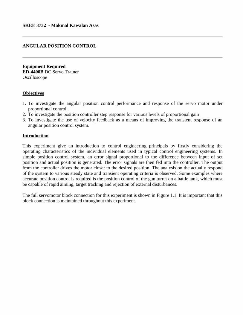
SKEE 3732 - Makmal Kawalan Asas
ANGULAR POSITION CONTROL
Equipment Required ED-4400B DC Servo Trainer
Oscilloscope
Objectives
1. To investigate the angular position control performance and response of the servo motor under
proportional control.
2. To investigate the position controller step response for various levels of proportional gain
3. To investigate the use of velocity feedback as a means of improving the transient response of an
angular position control system.
Introduction
This experiment give an introduction to control engineering principals by firstly considering the
operating characteristics of the individual elements used in typical control engineering systems. In
simple position control system, an error signal proportional to the difference between input of set
position and actual position is generated. The error signals are then fed into the controller. The output
from the controller drives the motor closer to the desired position. The analysis on the actually respond
of the system to various steady state and transient operating criteria is observed. Some examples where
accurate position control is required is the position control of the gun turret on a battle tank, which must
be capable of rapid aiming, target tracking and rejection of external disturbances.
The full servomotor block connection for this experiment is shown in Figure 1.1. It is important that this
block connection is maintained throughout this experiment.
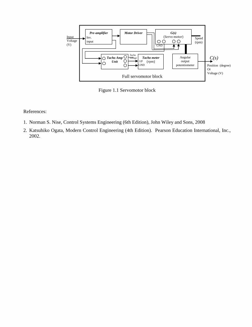
Figure 1.1 Servomotor block
References:
1. Norman S. Nise, Control Systems Engineering (6th Edition), John Wiley and Sons, 2008
2. Katsuhiko Ogata, Modern Control Engineering (4th Edition). Pearson Education International, Inc.,
2002.
Full servomotor block
G(s)
(Servo motor)
C(s)
Speed
(rpm)
Motor Driver Pre-amplifier
Input
Voltage
(V)
Angular
output
potentiometer Position (degree) Or
Voltage (V)
Inv.
input
GND
Tacho meter
(rpm) Tacho Amp
Unit
GND
I/P
Tacho
voltage
Procedure
In this laboratory, there are four experiments need to be performed.
A. Basic Tests and Dead Zones
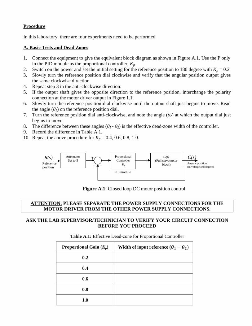
1. Connect the equipment to give the equivalent block diagram as shown in Figure A.1. Use the P only
in the PID module as the proportional controller, Kp
2. Switch on the power and set the initial setting for the reference position to 180 degree with Kp = 0.2
3. Slowly turn the reference position dial clockwise and verify that the angular position output gives
the same clockwise direction.
4. Repeat step 3 in the anti-clockwise direction.
5. If the output shaft gives the opposite direction to the reference position, interchange the polarity
connection at the motor driver output in Figure 1.1.
6. Slowly turn the reference position dial clockwise until the output shaft just begins to move. Read
the angle (θ1) on the reference position dial.
7. Turn the reference position dial anti-clockwise, and note the angle (θ2) at which the output dial just
begins to move.
8. The difference between these angles (θ1 - θ2) is the effective dead-zone width of the controller.
9. Record the difference in Table A.1.
10. Repeat the above procedure for Kp = 0.4, 0.6, 0.8, 1.0.
Figure A.1: Closed loop DC motor position control
ATTENTION: PLEASE SEPARATE THE POWER SUPPLY CONNECTIONS FOR THE
MOTOR DRIVER FROM THE OTHER POWER SUPPLY CONNECTIONS.
ASK THE LAB SUPERVISOR/TECHNICIAN TO VERIFY YOUR CIRCUIT CONNECTION
BEFORE YOU PROCEED
Table A.1: Effective Dead-zone for Proportional Controller
Proportional Gain (Kp) Width of input reference (
0.2
0.4
0.6
0.8
1.0
Attenuator
Set to 5 Reference position
+
_
Proportional
Controller
Kp
C(s) Angular position
(in voltage and degree)
G(s)
(Full servomotor
block)
R(s)
PID module

B. Angular Position Transducer Calibration
1. Use the same connection as in part A. 2. Switch on the power and set the initial setting for the output potentiometer position to 180 degree.
Record the corresponding voltage.
3. Slowly turn the servomotor output shaft until the output potentiometer gives a specified angle.
4. Choose 5 positive and 5 negative angles for the output potentiometer, and record the corresponding
position sensor output in Table B.1.
Table B.1: Output shaft angular position sensor calibration
Indicated angle of Output
shaft (degree)
Position sensor output
(V)
0
Decreasing negative angle value
Increasing positive angle value
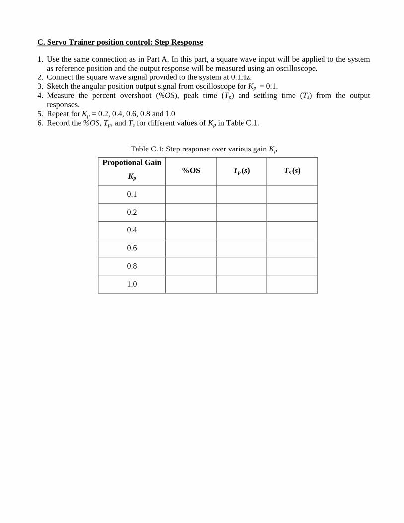
C. Servo Trainer position control: Step Response
1. Use the same connection as in Part A. In this part, a square wave input will be applied to the system
as reference position and the output response will be measured using an oscilloscope.
2. Connect the square wave signal provided to the system at 0.1Hz.
3. Sketch the angular position output signal from oscilloscope for Kp = 0.1.
4. Measure the percent overshoot (%OS), peak time (Tp) and settling time (Ts) from the output
responses.
5. Repeat for Kp = 0.2, 0.4, 0.6, 0.8 and 1.0
6. Record the %OS, Tp, and Ts for different values of Kp in Table C.1.
Table C.1: Step response over various gain Kp
Propotional Gain
Kp %OS Tp (s) Ts (s)
0.1
0.2
0.4
0.6
0.8
1.0

D. Angular Position Control: Velocity Feedback
1. Connect the equipment corresponds to the block diagram shown in Figure D.1. The difference is just
an additional minor feedback loop as compared to the connection in Part C.
Figure D.1: Closed loop DC motor Position control with velocity feedback
2. Set the Proportional controller, Kp = 0.2 and the velocity feedback gain, Kv = 1.
3. Sketch the angular position output signal read from oscilloscope.
4. Measure %OS, Tp, and Ts, from the output response.
5. Repeat for Kp = 0.2, 0.4, 0.6, 0.8 and 1.0
6. Record the %OS, Tp, and Ts for different values of Kp in Table D.1.
Table D.1: Step response (using velocity feedback) over various gain Kp
Propotional Gain
Kp %OS Tp (s) Ts (s)
0.2
0.4
0.6
0.8
1.0
Square wave reference position
+
_
Proportional Controller
Kp
R(s)
Kv
Tacho signal
C(s) Angular position
(in voltage and degree)
G(s)
(Full servomotor
block) _ + Attenuator
Set to 5
Discussion and general conclusion
1) From Experiment B:
a. Plot the graph using the data from Table B.1.
b. Calculate the angle sensor constant, V
K
c. Describe the relationship between the indicated angle and the position sensor output voltage.
2) From Experiment C:
a. Discuss the relative performance of the controller with various gains Kp.
b. Sketch the output waveform from the oscilloscope.
3) From Experiment D:
a. Explain why the velocity feedback has a beneficial effect on the system transient response.
b. Sketch the output waveform from the oscilloscope.
For long report.
1. In your own words, explain the relationship between the voltage and the position angle of the
DC motor.
2. Draw in details, the output response of the system for different gains.
3. Carry out the time domain analysis on the system output response.
4. Discuss the effect of velocity feedback on the system transient response.
5. By using Matlab, compare your simulation results with experimental results.