polyaniline composite membranes synthesis in … composite membranes synthesis in presence of...
TRANSCRIPT
Jurnal Kejuruteraan (UKM Engineering Journal) 29(2)2017: 13 pages, In Press
ISSN:0128-0198 E-ISSN:2289-7526
1
Polyaniline Composite Membranes Synthesis in Presence of Various Acid
Dopants for Pressure Filtration
(Sintesis Membran Komposit Polyanilin dengan Kehadiran Pelbagai Jenis Asid Dopan untunk Penursan
Tekanan)
Rosiah Rohani*, Izzati Izni Yusoff, Farah Adlyna Mey Efdi & Mohd Usman Mohd Junaidi
Faculty of Engineering & Built Environment, Universiti Kebangsaan Malaysia, Malaysia
Asif Ali Qaiser
University of Engineering & Technology, Pakistan
ABSTRACT
Polyaniline is a conductive polymer that is recently used as a material in producing a pressure filtration
membrane. Polyaniline can be doped in various acids as dopants of different sizes and shapes to modify its
inherent properties to produce membrane with high flux and rejection. This work is aimed to fabricate
polyaniline composite membrane in presence of different acids as dopants namely hydrochloric acid, maleic
acid, poly(methyl vinylether) acid (PMVEA) and polyacrylic acid (PAA). This polyaniline was coated onto
microporous polyvinylidene fluoride (PVDF) support by using a specially fabricated two compartment cell. The
field emission scanning electron microscope (FESEM) results show that the morphology of the coated
polyaniline on PVDF membrane support is in globular shapes, which elongates at different sizes depending to
the acid used. From the thermal analysis, the melting point of polyaniline coated PVDF membrane remains at
260 °C, similar as obtained in the pristine microporous PVDF indicating no thermal change upon polyaniline
coating. From all membranes prepared, the doped polyaniline membrane possessed a good conductivity value
except for polyaniline-PMVEA membrane, which has the lowest value. In terms of the membrane filtration
performance, which was measured based on the flux of pure water and polyethylene glycol (PEG) rejection,
polyaniline-PMVEA membrane has a high flux and the highest PEG rejection. This result indicates that the
conductivity does not influence much on the membrane filtration performance, but rather due to the physical
coating itself. Different acid dopants present during polyaniline coating will lead to different filtration
performance.
Keywords: Polyaniline; Composite Membrane; Chemical Polymerization; Acid Dopant; Pressure Filtration
INTRODUCTION
Membrane technology has recently evolved in many industries by implying the recovery and reuse or sale of
previously wasted materials (Rohani et al. 2011). This practice enables these industries to be more
environmental friendly by decreasing the amount of waste and become more cost-effective, as some high-value
materials can be recovered from the waste stream. The water and wastewater treatment industry is one of the
main industries that dependent on membrane technology as one of the treatment and recovery technology.
However, commercially used membranes such as polysulfone (PSf) have limitations where they have fixed
separation selectivity (Yusoff et al. 2016). This requires development of new membrane to allow changeable
separation selectivity. Additionally, effective removal of uncharged contaminants from wastewater is
problematic using low pressure membrane operation, which required additional chemical treatment steps
(Pignatello et al. 2006). Thus, the introduction of conducting polymer (CP) in the manufacturing of a pressure
filtration membrane is attractive due to its high electrical conductivity and mechanical flexibility (Yusoff et al.
2016), which is very promising to overcome commercial membrane problems.
CP such as polyaniline has been extensively investigated to elucidate their intrinsic transport properties
owing to their low dimensionality, light weight, biological compatibility for ease of cost and manufacturing
(Kumar et al. 2004; Richard et al. 2014). In future, membrane fabricated from CP material could improve the
complex molecular separations that enable by existing selective polymer membrane (Baker 2000). Besides
having desirable properties, CP can be tuned with various electrolytes to influence the membrane free volume,
which controls permeance diffusivity (Anderson et al. 1991; Rohani et al. 2016). Hence, the selectivity can be
controlled by manipulating the electrical conductivity on the membrane (Stassen et al. 1995; Sairam et al. 2006).
According to Sairam et al. (Sairam et al. 2006), they have introduced and investigated polyaniline as a potential
Jurnal Kejuruteraan (UKM Engineering Journal) 29(2)2017: 13 pages, In Press
ISSN:0128-0198 E-ISSN:2289-7526
2
CP, used to fabricate a pressure filtration membrane. Polyaniline is of interest as it can easily form free-standing
film and it can be used in various applications such as fuel cells, batteries, and sensors (Ekarat & Stephen 2009;
Ghani et al. 2012). Moreover, unique characteristics and low manufacturing cost of polyaniline are the main
reasons to develop polyaniline based membranes (Kolla et al. 2005; Thanpitcha et al. 2008; Xu et al. 2015; Lv et
al. 2016).
Previously, there are several methods that can be applied in polyaniline membranes fabrication including
non-solvent induced phase separation (Liao et al. 2014), flash welding (Liao et al. 2013) and polymer blending
(McVerry et al. 2013; Lv et al. 2016) to increase its conductivity and hydrophilicity. According to Mansouri et
al. (Mansouri et al. 2010), polyaniline membrane fabricated with high electrical conductivity and great
hydrophilicity properties tend to have better resistance towards organic and biological fouling. Another potential
approach in polyaniline fabrication applied in the recent works (Pournaghi-Azar et al. 2007; Lu et al. 2011) is by
using electrochemical polymerization to promote the development of polyaniline coating composite membranes
with higher electrical conductivity and improved mechanical properties. However, free standing polyaniline in
the form of continuous flat membrane is relatively less durable than the present commercial membranes.
Therefore, polyaniline composite membranes were prepared to improve its mechanical strength and filtration
performance.
Various strategies have been explored by controlling the parameters involved during the chemical
polymerization of polyaniline such as different acid dopants used, polymerization temperatures times, etc
(Chowdhury & Saha 2005). The presence of acid dopant has found to influence the CP in terms of polymer
structure and the polymerization reaction rate. Desilvestro et al. (Desilvestro & Scheifele 1993) observed that
polymerization rate of polyaniline from acidic solutions was influenced by the acid dopant in which it was
fabricated with the polymerization reaction has occurred faster in sulfuric acid (H2SO4) solution than in HCl.
The polymerization rate has also influenced the morphologicak properties of the synthesized polyaniline
membranes. Polyaniline fabricated by Desilvestro et al. (Desilvestro & Scheifele 1993) using HCl dopant was
found to be in a fibrils packed network with diameters of 0.2 - 0.3 µm. Meanwhile, polyaniline membrane
polymerized in H2SO4 dopant appeared in short fibrous stumps with typically length less than 0.5 µm. This
shows that different acid dopants presence during polymerization may results in different polyaniline membrane
microstructures.
Therefore, the aim of this work is to fabricate pressure filtration membranes from polyaniline by coating it
onto microporous polyvinylidene fluoride (PVDF) as the membrane support in presence of various acid
dopants. The chemical polymerization of polyaniline from aniline and ammonium persulfate (APS) was
conducted in a specially fabricated two-compartment cell where the aniline and APS acidic solution were filled
in each compartment that was separated by the microporous PVDF in between them. Apart from different types
of acid dopant effect, the effects of polymerization times during chemical polymerization were also investigated.
The synthesized membranes were characterized by using Fourier Transform Infrared (FTIR) spectroscopy for
their chemical properties, thermal properties by differential scanning calorimetry (DSC) while surface
morphology of the membranes was analysed via field emission scanning electron microscopy (FESEM). The
membrane electrical conductivity was measured by Inductance, Capacitance and Resistance meter (LCR meter)
and the filtration performance of the membranes were tested via flux and rejection of Polyethylene glycol (PEG)
at different molecular weights (MW) through the membranes in a dead-end filtration unit.
MATERIALS AND METHODS
Materials
The microporous polyvinylidene fluoride (PVDF) support of 0.01 µm porosity was purchased from Hangzhou
ANOW Microfiltration Co. Ltd., China. Aniline monomer, ammonium persulfate (APS), poly(methyl vinyl
ether-alt-maleic acid) (PMVEA) (MW 216, 000 g/mol) and maleic acid (MA) (MW 116.07 g/mol) were
purchased from Sigma-Aldrich Chemical, USA. All these chemicals including Polyacrylic acid (PAA) (MW
651.94 g/mol, Alfa Aesar, USA) and hydrochloric acid (HCl) (Merck) were used as received.
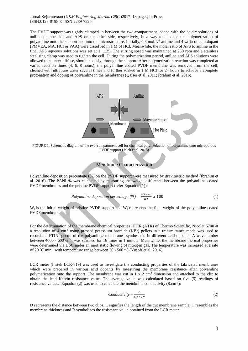
Preparation of Polyaniline Composite Membranes
Polyaniline membranes were synthesized onto microporous PVDF supports in presence of various acid dopants
to enhance the performance of the membranes for application in a pressure filtration unit especially in the
ultrafiltration (UF) and nanofiltration (NF) ranges. The polymerization of polyaniline was performed by
chemical polymerization reaction via diffusion cell technique in a specially fabricated two-compartment cell.
Subsequently, the PVDF was sandwiched between the solution of aniline and APS aqueous solutions at two
different compartments in the cell. The schematic diagram of the two-compartment cell is presented in Figure 1.
Jurnal Kejuruteraan (UKM Engineering Journal) 29(2)2017: 13 pages, In Press
ISSN:0128-0198 E-ISSN:2289-7526
3
The PVDF support was tightly clamped in between the two-compartment loaded with the acidic solutions of
aniline on one side and APS on the other side, respectively, in a way to enhance the polymerization of
polyaniline onto the support and into the microstructure. Initially, 0.8 mol.L-1 aniline and 4 wt.% of acid dopant
(PMVEA, MA, HCl or PAA) were dissolved in 1 M of HCl. Meanwhile, the molar ratio of APS to aniline in the
final APS aqueous solutions was set at 1: 1.25. The stirring speed was maintained at 250 rpm and a stainless
steel ring clamp was used to tighten the cell. During the polymerization period, aniline and APS solutions were
allowed to counter-diffuse, simultaneously, through the support. After polymerization reaction was completed at
varied reaction times (4, 6, 8 hours), the polyaniline coated PVDF membrane was removed from the cell,
cleaned with ultrapure water several times and further soaked in 1 M HCl for 24 hours to achieve a complete
protonation and doping of polyaniline in the membranes (Qaiser et al. 2011; Ibrahim et al. 2016).
FIGURE 1. Schematic diagram of the two-compartment cell for chemical polymerization of polyaniline onto microporous
PVDF support (Jaleh et al. 2015)
Membrane Characterization
Polyaniline deposition percentage (%) on the PVDF support were measured by gravimetric method (Ibrahim et
al. 2016). The PANI % was calculated by measuring the weight difference between the polyaniline coated
PVDF membranes and the pristine PVDF support (refer Equation (1)):
Polyaniline deposition percentage (%) = 𝑊𝑓−𝑊𝑖
𝑊𝑓 𝑥 100 (1)
Wi is the initial weight of pristine PVDF support and Wf represents the final weight of the polyaniline coated
PVDF membrane.
For the determination of the membrane chemical properties, FTIR (ATR) of Thermo Scientific, Nicolet 6700 at
a resolution of 4 cm-1 using pressed potassium bromide (KBr) pellets in a transmittance mode was used to
record the FTIR spectra of the polyaniline membranes synthesized in different acid dopants. A wavenumber
between 4000 - 600 cm-1 was scanned for 16 times in 1 minute. Meanwhile, the membrane thermal properties
were determined via DSC under an inert static flowing of nitrogen gas. The temperature was increased at a rate
of 20 oC min-1 with temperature range between 30 - 500 oC (Yusoff et al. 2016).
LCR meter (Instek LCR-819) was used to investigate the conducting properties of the fabricated membranes
which were prepared in various acid dopants by measuring the membrane resistance after polyaniline
polymerization onto the support. The membrane was cut in 1 x 2 cm2 dimension and attached to the clip to
obtain the lead Kelvin resistance value. The average value was calculated based on five (5) readings of
resistance values. Equation (2) was used to calculate the membrane conductivity (S.cm-1):
Conductivity = D
L x T x R (2)
D represents the distance between two clips, L signifies the length of the cut membrane sample, T resembles the
membrane thickness and R symbolizes the resistance value obtained from the LCR meter.
Jurnal Kejuruteraan (UKM Engineering Journal) 29(2)2017: 13 pages, In Press
ISSN:0128-0198 E-ISSN:2289-7526
4
FESEM of Gemini, SUPRA 55VP-ZEISS equipped with an Energy Dispersive X-ray Analysis (EDX) system
where this system was used to observe the surface and cross sectional morphology of the polyaniline coated
PVDF membrane doped in different acid dopants. During the sample preparation, the membrane sample was
dried, cut and mounted onto a metal stud. It was then gold sputtered. Finally, the prepared sample was being
observed under the FESEM at 3 kV and 10 kV accelerating voltage.
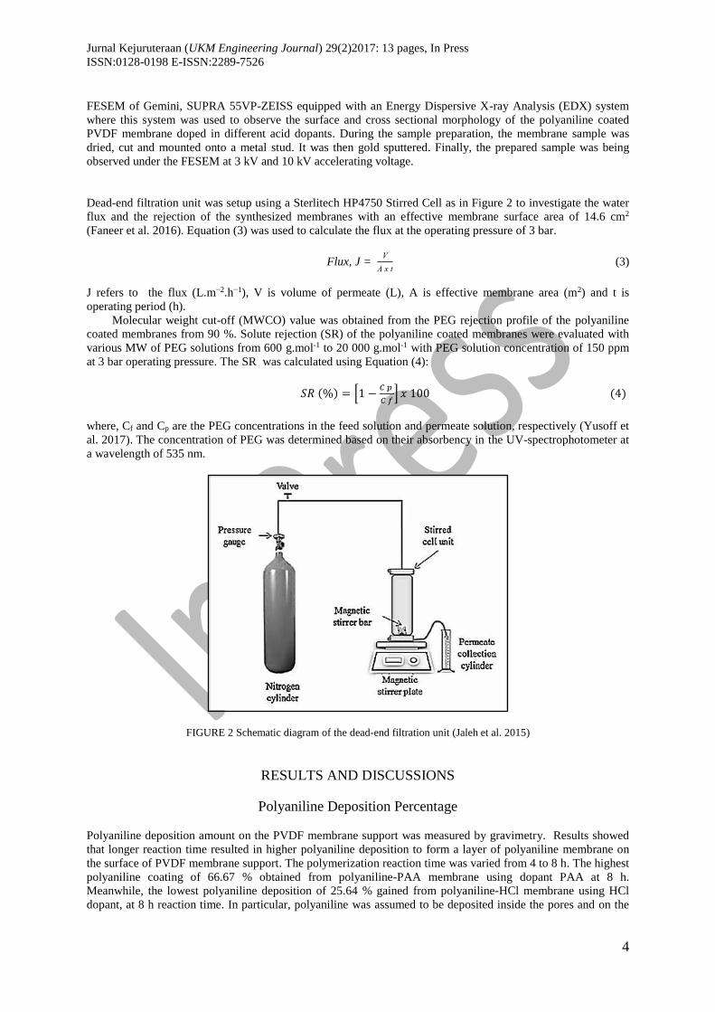
Dead-end filtration unit was setup using a Sterlitech HP4750 Stirred Cell as in Figure 2 to investigate the water
flux and the rejection of the synthesized membranes with an effective membrane surface area of 14.6 cm2
(Faneer et al. 2016). Equation (3) was used to calculate the flux at the operating pressure of 3 bar.
Flux, J = V
A x t (3)
J refers to the flux (L.m−2.h−1), V is volume of permeate (L), A is effective membrane area (m2) and t is
operating period (h).
Molecular weight cut-off (MWCO) value was obtained from the PEG rejection profile of the polyaniline
coated membranes from 90 %. Solute rejection (SR) of the polyaniline coated membranes were evaluated with
various MW of PEG solutions from 600 g.mol-1 to 20 000 g.mol-1 with PEG solution concentration of 150 ppm
at 3 bar operating pressure. The SR was calculated using Equation (4):
𝑆𝑅 (%) = [1 −𝐶 𝑝
𝐶 𝑓] 𝑥 100 (4)
where, Cf and Cp are the PEG concentrations in the feed solution and permeate solution, respectively (Yusoff et
al. 2017). The concentration of PEG was determined based on their absorbency in the UV-spectrophotometer at
a wavelength of 535 nm.
FIGURE 2 Schematic diagram of the dead-end filtration unit (Jaleh et al. 2015)
RESULTS AND DISCUSSIONS
Polyaniline Deposition Percentage
Polyaniline deposition amount on the PVDF membrane support was measured by gravimetry. Results showed
that longer reaction time resulted in higher polyaniline deposition to form a layer of polyaniline membrane on
the surface of PVDF membrane support. The polymerization reaction time was varied from 4 to 8 h. The highest
polyaniline coating of 66.67 % obtained from polyaniline-PAA membrane using dopant PAA at 8 h.
Meanwhile, the lowest polyaniline deposition of 25.64 % gained from polyaniline-HCl membrane using HCl
dopant, at 8 h reaction time. In particular, polyaniline was assumed to be deposited inside the pores and on the
Jurnal Kejuruteraan (UKM Engineering Journal) 29(2)2017: 13 pages, In Press
ISSN:0128-0198 E-ISSN:2289-7526
5
surface of the PVDF membrane during the polymerization period in the two-compartment cell. Polyaniline has
formed in bulk membrane by the counter-diffusion of aniline and APS oxidant through the PVDF support
(Qaiser et al. 2011). During the polymerization process, polyaniline deposition was initiated on the aniline-
facing side of the membrane and maintained its asymmetric growth in the bulk membrane throughout the
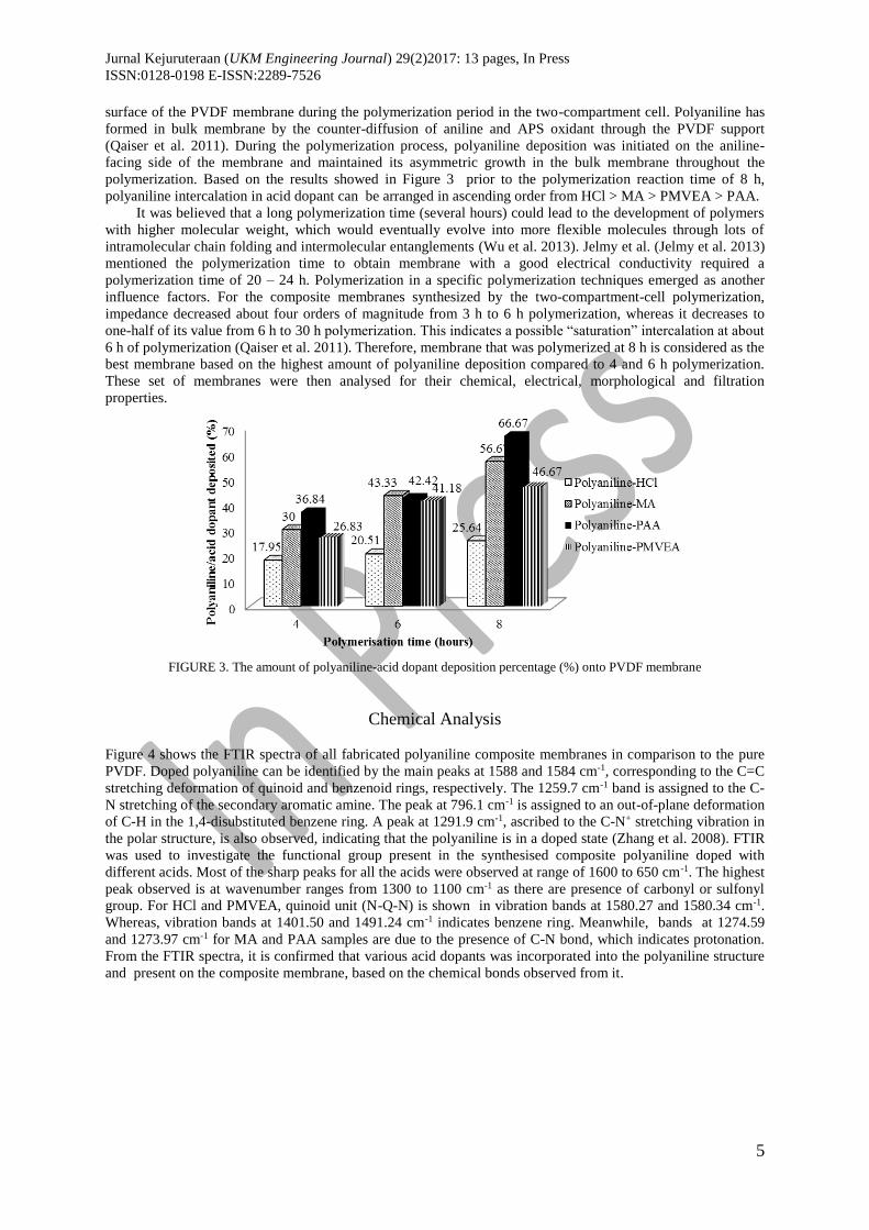
polymerization. Based on the results showed in Figure 3 prior to the polymerization reaction time of 8 h,
polyaniline intercalation in acid dopant can be arranged in ascending order from HCl > MA > PMVEA > PAA.
It was believed that a long polymerization time (several hours) could lead to the development of polymers
with higher molecular weight, which would eventually evolve into more flexible molecules through lots of
intramolecular chain folding and intermolecular entanglements (Wu et al. 2013). Jelmy et al. (Jelmy et al. 2013)
mentioned the polymerization time to obtain membrane with a good electrical conductivity required a
polymerization time of 20 – 24 h. Polymerization in a specific polymerization techniques emerged as another
influence factors. For the composite membranes synthesized by the two-compartment-cell polymerization,
impedance decreased about four orders of magnitude from 3 h to 6 h polymerization, whereas it decreases to
one-half of its value from 6 h to 30 h polymerization. This indicates a possible “saturation” intercalation at about
6 h of polymerization (Qaiser et al. 2011). Therefore, membrane that was polymerized at 8 h is considered as the
best membrane based on the highest amount of polyaniline deposition compared to 4 and 6 h polymerization.
These set of membranes were then analysed for their chemical, electrical, morphological and filtration
properties.
FIGURE 3. The amount of polyaniline-acid dopant deposition percentage (%) onto PVDF membrane
Chemical Analysis
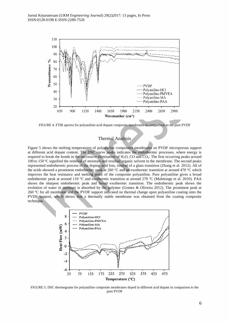
Figure 4 shows the FTIR spectra of all fabricated polyaniline composite membranes in comparison to the pure
PVDF. Doped polyaniline can be identified by the main peaks at 1588 and 1584 cm-1, corresponding to the C=C
stretching deformation of quinoid and benzenoid rings, respectively. The 1259.7 cm-1 band is assigned to the C-
N stretching of the secondary aromatic amine. The peak at 796.1 cm-1 is assigned to an out-of-plane deformation
of C-H in the 1,4-disubstituted benzene ring. A peak at 1291.9 cm-1, ascribed to the C-N+ stretching vibration in
the polar structure, is also observed, indicating that the polyaniline is in a doped state (Zhang et al. 2008). FTIR
was used to investigate the functional group present in the synthesised composite polyaniline doped with
different acids. Most of the sharp peaks for all the acids were observed at range of 1600 to 650 cm-1. The highest
peak observed is at wavenumber ranges from 1300 to 1100 cm-1 as there are presence of carbonyl or sulfonyl
group. For HCl and PMVEA, quinoid unit (N-Q-N) is shown in vibration bands at 1580.27 and 1580.34 cm-1.
Whereas, vibration bands at 1401.50 and 1491.24 cm-1 indicates benzene ring. Meanwhile, bands at 1274.59
and 1273.97 cm-1 for MA and PAA samples are due to the presence of C-N bond, which indicates protonation.
From the FTIR spectra, it is confirmed that various acid dopants was incorporated into the polyaniline structure
and present on the composite membrane, based on the chemical bonds observed from it.
Jurnal Kejuruteraan (UKM Engineering Journal) 29(2)2017: 13 pages, In Press
ISSN:0128-0198 E-ISSN:2289-7526
6
FIGURE 4. FTIR spectra for polyaniline-acid dopant composite membranes in comparison to the pure PVDF
Thermal Analysis
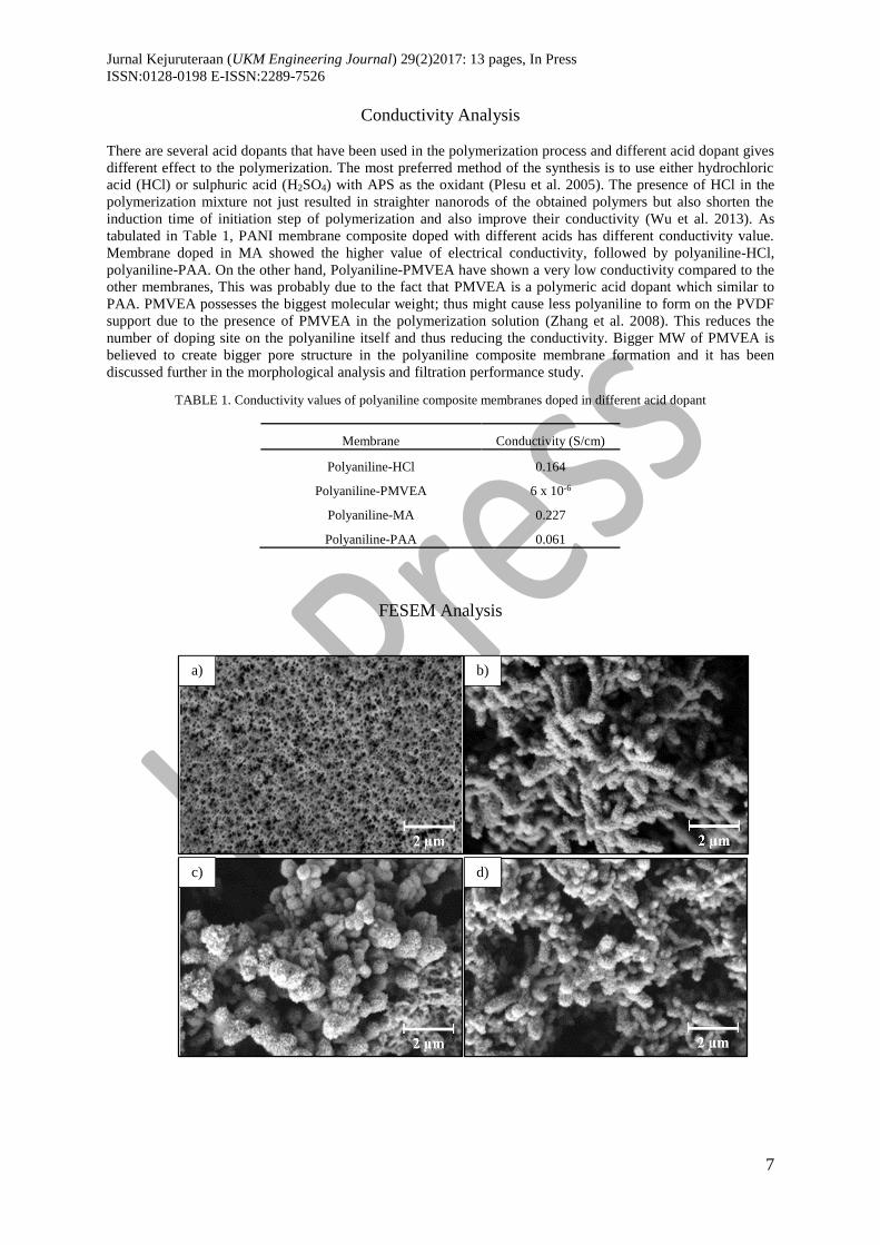
Figure 5 shows the melting temperatures of polyaniline composites membranes on PVDF microporous support
at different acid dopant content. The DSC curve peaks indicates the endothermic processes, where energy is
required to break the bonds in the successive elimination of H2O, CO and CO2. The first occurring peaks around
100 to 150 oC signified the removal of moisture and residual organic solvent in the membrane. The second peaks
represented endothermic process of the doping acid loss, instead of a glass transition (Zhang et al. 2012). All of
the acids showed a prominent endothermic peak at 260 oC and an exothermic transition at around 470 oC which
improves the heat resistance and melting point of the composite polyaniline. Pure polyaniline gives a broad
endothermic peak at around 110 oC and exothermic transition at around 270 oC (Malmonge et al. 2010). PAA
shows the sharpest endothermic peak and broad exothermic transition. The endothermic peak shows the
evolution of water in moisture is absorbed by the polymer (Gomes & Oliveira 2012). The prominent peak at
260 °C for all membrane and the PVDF support indicated no thermal change upon polyaniline coating onto the
PVDF support, which shows that a thermally stable membrane was obtained from the coating composite
technique.
FIGURE 5. DSC thermograms for polyaniline composite membranes doped in different acid dopant in comparison to the
pure PVDF
Jurnal Kejuruteraan (UKM Engineering Journal) 29(2)2017: 13 pages, In Press
ISSN:0128-0198 E-ISSN:2289-7526
7
Conductivity Analysis
There are several acid dopants that have been used in the polymerization process and different acid dopant gives
different effect to the polymerization. The most preferred method of the synthesis is to use either hydrochloric
acid (HCl) or sulphuric acid (H2SO4) with APS as the oxidant (Plesu et al. 2005). The presence of HCl in the
polymerization mixture not just resulted in straighter nanorods of the obtained polymers but also shorten the
induction time of initiation step of polymerization and also improve their conductivity (Wu et al. 2013). As
tabulated in Table 1, PANI membrane composite doped with different acids has different conductivity value.
Membrane doped in MA showed the higher value of electrical conductivity, followed by polyaniline-HCl,
polyaniline-PAA. On the other hand, Polyaniline-PMVEA have shown a very low conductivity compared to the
other membranes, This was probably due to the fact that PMVEA is a polymeric acid dopant which similar to
PAA. PMVEA possesses the biggest molecular weight; thus might cause less polyaniline to form on the PVDF
support due to the presence of PMVEA in the polymerization solution (Zhang et al. 2008). This reduces the
number of doping site on the polyaniline itself and thus reducing the conductivity. Bigger MW of PMVEA is
believed to create bigger pore structure in the polyaniline composite membrane formation and it has been
discussed further in the morphological analysis and filtration performance study.
TABLE 1. Conductivity values of polyaniline composite membranes doped in different acid dopant
Membrane Conductivity (S/cm)
Polyaniline-HCl 0.164
Polyaniline-PMVEA 6 x 10⁻⁶
Polyaniline-MA 0.227
Polyaniline-PAA 0.061
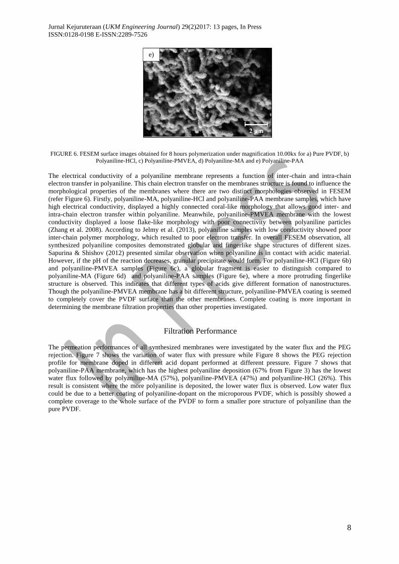
FESEM Analysis
a)
d) c)
b)
Jurnal Kejuruteraan (UKM Engineering Journal) 29(2)2017: 13 pages, In Press
ISSN:0128-0198 E-ISSN:2289-7526
8
FIGURE 6. FESEM surface images obtained for 8 hours polymerization under magnification 10.00kx for a) Pure PVDF, b)
Polyaniline-HCl, c) Polyaniline-PMVEA, d) Polyaniline-MA and e) Polyaniline-PAA
The electrical conductivity of a polyaniline membrane represents a function of inter-chain and intra-chain
electron transfer in polyaniline. This chain electron transfer on the membranes structure is found to influence the
morphological properties of the membranes where there are two distinct morphologies observed in FESEM
(refer Figure 6). Firstly, polyaniline-MA, polyaniline-HCl and polyaniline-PAA membrane samples, which have
high electrical conductivity, displayed a highly connected coral-like morphology that allows good inter- and
intra-chain electron transfer within polyaniline. Meanwhile, polyaniline-PMVEA membrane with the lowest
conductivity displayed a loose flake-like morphology with poor connectivity between polyaniline particles
(Zhang et al. 2008). According to Jelmy et al. (2013), polyaniline samples with low conductivity showed poor
inter-chain polymer morphology, which resulted to poor electron transfer. In overall FESEM observation, all
synthesized polyaniline composites demonstrated globular and fingerlike shape structures of different sizes.
Sapurina & Shishov (2012) presented similar observation when polyaniline is in contact with acidic material.
However, if the pH of the reaction decreases, granular precipitate would form. For polyaniline-HCl (Figure 6b)
and polyaniline-PMVEA samples (Figure 6c), a globular fragment is easier to distinguish compared to
polyaniline-MA (Figure 6d) and polyaniline-PAA samples (Figure 6e), where a more protruding fingerlike
structure is observed. This indicates that different types of acids give different formation of nanostructures.
Though the polyaniline-PMVEA membrane has a bit different structure, polyaniline-PMVEA coating is seemed
to completely cover the PVDF surface than the other membranes. Complete coating is more important in
determining the membrane filtration properties than other properties investigated.
Filtration Performance
The permeation performances of all synthesized membranes were investigated by the water flux and the PEG
rejection. Figure 7 shows the variation of water flux with pressure while Figure 8 shows the PEG rejection
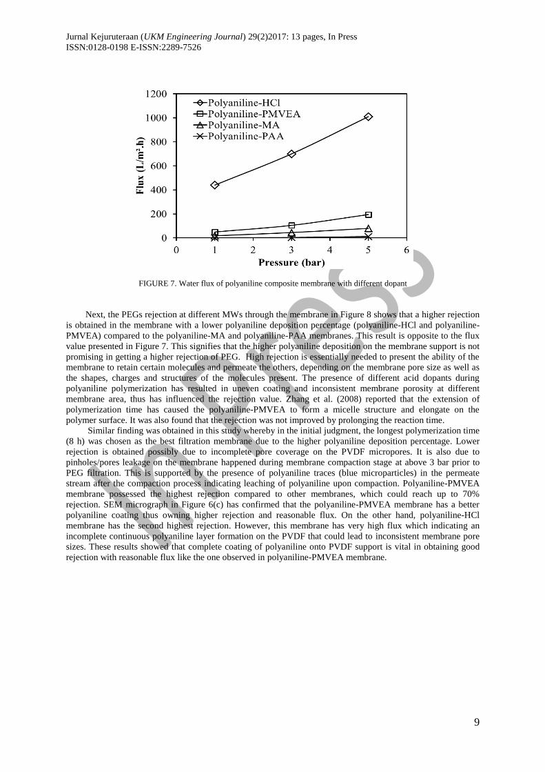
profile for membrane doped in different acid dopant performed at different pressure. Figure 7 shows that
polyaniline-PAA membrane, which has the highest polyaniline deposition (67% from Figure 3) has the lowest
water flux followed by polyaniline-MA (57%), polyaniline-PMVEA (47%) and polyaniline-HCl (26%). This
result is consistent where the more polyaniline is deposited, the lower water flux is observed. Low water flux
could be due to a better coating of polyaniline-dopant on the microporous PVDF, which is possibly showed a
complete coverage to the whole surface of the PVDF to form a smaller pore structure of polyaniline than the
pure PVDF.
e)
Jurnal Kejuruteraan (UKM Engineering Journal) 29(2)2017: 13 pages, In Press
ISSN:0128-0198 E-ISSN:2289-7526
9
FIGURE 7. Water flux of polyaniline composite membrane with different dopant
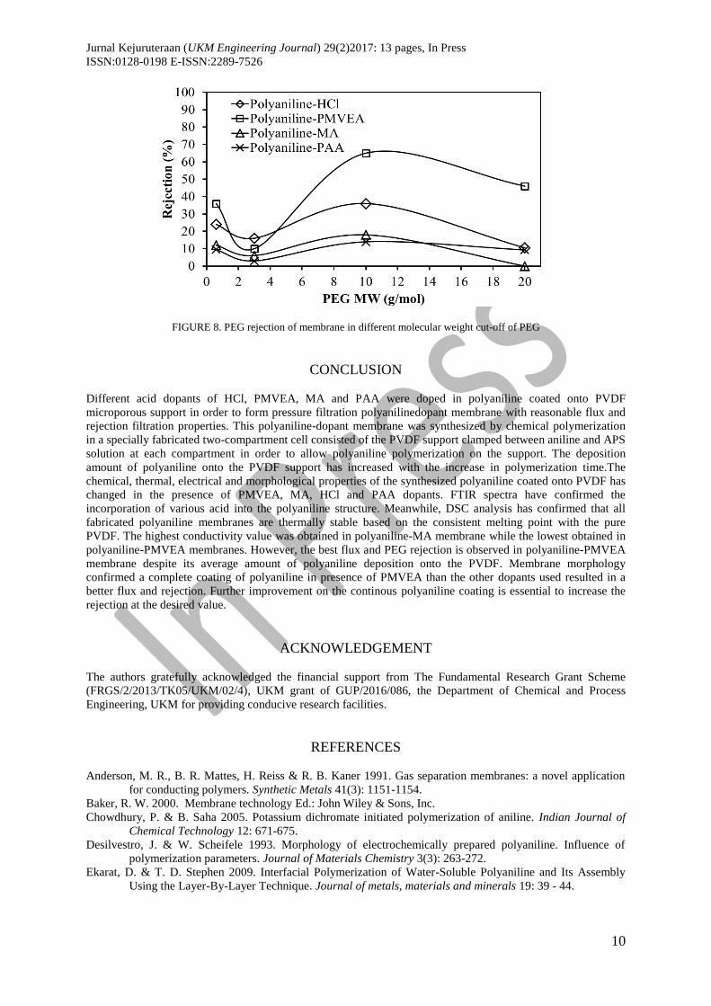
Next, the PEGs rejection at different MWs through the membrane in Figure 8 shows that a higher rejection
is obtained in the membrane with a lower polyaniline deposition percentage (polyaniline-HCl and polyaniline-
PMVEA) compared to the polyaniline-MA and polyaniline-PAA membranes. This result is opposite to the flux
value presented in Figure 7. This signifies that the higher polyaniline deposition on the membrane support is not
promising in getting a higher rejection of PEG. High rejection is essentially needed to present the ability of the
membrane to retain certain molecules and permeate the others, depending on the membrane pore size as well as
the shapes, charges and structures of the molecules present. The presence of different acid dopants during
polyaniline polymerization has resulted in uneven coating and inconsistent membrane porosity at different
membrane area, thus has influenced the rejection value. Zhang et al. (2008) reported that the extension of
polymerization time has caused the polyaniline-PMVEA to form a micelle structure and elongate on the
polymer surface. It was also found that the rejection was not improved by prolonging the reaction time.
Similar finding was obtained in this study whereby in the initial judgment, the longest polymerization time
(8 h) was chosen as the best filtration membrane due to the higher polyaniline deposition percentage. Lower
rejection is obtained possibly due to incomplete pore coverage on the PVDF micropores. It is also due to
pinholes/pores leakage on the membrane happened during membrane compaction stage at above 3 bar prior to
PEG filtration. This is supported by the presence of polyaniline traces (blue microparticles) in the permeate
stream after the compaction process indicating leaching of polyaniline upon compaction. Polyaniline-PMVEA
membrane possessed the highest rejection compared to other membranes, which could reach up to 70%
rejection. SEM micrograph in Figure 6(c) has confirmed that the polyaniline-PMVEA membrane has a better
polyaniline coating thus owning higher rejection and reasonable flux. On the other hand, polyaniline-HCl
membrane has the second highest rejection. However, this membrane has very high flux which indicating an
incomplete continuous polyaniline layer formation on the PVDF that could lead to inconsistent membrane pore
sizes. These results showed that complete coating of polyaniline onto PVDF support is vital in obtaining good
rejection with reasonable flux like the one observed in polyaniline-PMVEA membrane.
Jurnal Kejuruteraan (UKM Engineering Journal) 29(2)2017: 13 pages, In Press
ISSN:0128-0198 E-ISSN:2289-7526
10
FIGURE 8. PEG rejection of membrane in different molecular weight cut-off of PEG
CONCLUSION
Different acid dopants of HCl, PMVEA, MA and PAA were doped in polyaniline coated onto PVDF
microporous support in order to form pressure filtration polyanilinedopant membrane with reasonable flux and
rejection filtration properties. This polyaniline-dopant membrane was synthesized by chemical polymerization
in a specially fabricated two-compartment cell consisted of the PVDF support clamped between aniline and APS
solution at each compartment in order to allow polyaniline polymerization on the support. The deposition
amount of polyaniline onto the PVDF support has increased with the increase in polymerization time.The
chemical, thermal, electrical and morphological properties of the synthesized polyaniline coated onto PVDF has
changed in the presence of PMVEA, MA, HCl and PAA dopants. FTIR spectra have confirmed the
incorporation of various acid into the polyaniline structure. Meanwhile, DSC analysis has confirmed that all
fabricated polyaniline membranes are thermally stable based on the consistent melting point with the pure
PVDF. The highest conductivity value was obtained in polyaniline-MA membrane while the lowest obtained in
polyaniline-PMVEA membranes. However, the best flux and PEG rejection is observed in polyaniline-PMVEA
membrane despite its average amount of polyaniline deposition onto the PVDF. Membrane morphology
confirmed a complete coating of polyaniline in presence of PMVEA than the other dopants used resulted in a
better flux and rejection. Further improvement on the continous polyaniline coating is essential to increase the
rejection at the desired value.
ACKNOWLEDGEMENT
The authors gratefully acknowledged the financial support from The Fundamental Research Grant Scheme
(FRGS/2/2013/TK05/UKM/02/4), UKM grant of GUP/2016/086, the Department of Chemical and Process
Engineering, UKM for providing conducive research facilities.
REFERENCES
Anderson, M. R., B. R. Mattes, H. Reiss & R. B. Kaner 1991. Gas separation membranes: a novel application
for conducting polymers. Synthetic Metals 41(3): 1151-1154.
Baker, R. W. 2000. Membrane technology Ed.: John Wiley & Sons, Inc.
Chowdhury, P. & B. Saha 2005. Potassium dichromate initiated polymerization of aniline. Indian Journal of
Chemical Technology 12: 671-675.
Desilvestro, J. & W. Scheifele 1993. Morphology of electrochemically prepared polyaniline. Influence of
polymerization parameters. Journal of Materials Chemistry 3(3): 263-272.
Ekarat, D. & T. D. Stephen 2009. Interfacial Polymerization of Water-Soluble Polyaniline and Its Assembly
Using the Layer-By-Layer Technique. Journal of metals, materials and minerals 19: 39 - 44.
Jurnal Kejuruteraan (UKM Engineering Journal) 29(2)2017: 13 pages, In Press
ISSN:0128-0198 E-ISSN:2289-7526
11
Faneer, K. A., R. Rohani & A. W. Mohammad 2016. Polyethersulfone Nanofiltration Membrane Incorporated
With Silicon Dioxide Prepared by Phase Inversion Method for Xylitol Purification. Polymers &
Polymer Composites 24: 803-808.
Ghani, S. A., A. Zakaria, A. Y. M. Shakaff, M. N. Ahmad & A. H. Abdullah 2012. Enhancing Conductive
Polymer Performance Using Eggshell for Ammonia Senso. Journal of Physical Science 23(2): 73 - 83.
Gomes, E. C. & M. A. S. Oliveira 2012. Chemical Polymerization of Aniline in Hydrochloric Acid (HCl) and
Formic Acid (HCOOH) Media. Differences Between the Two Synthesized Polyanilines. American
Journal of Polymer Science 2(2): 5-13.
Ibrahim, F., R. Rohani & A. W. Mohammad 2016. Polyaniline Multi-Coated onto Polyvinylidene Fluoride and
Silicon Elastomer for Pressure Filtration Membranes. Malaysian Journal of Analytical Science 20(6):
1498-1509.
Jaleh, B., N. Gavary, P. Fakhri, N. Muensit & S. M. Taheri 2015. Characteristics of PVDF membranes
irradiated by electron beam. Membranes (Basel) 5(1): 1-10.
Jelmy, E. J., S. Ramakrishnan, S. Devanathan, M. Rangaranjan & N. K. Kothurkar 2013. Optimization of the
Conductivity and Yield of Chemically Synthesized Polyaniline Using a Design of Experiments.
Journal of Applied Polymer Science: 1047 - 1057.
Kolla, H. S., S. P. Surwade, X. Zhang, A. G. MacDiarmid & S. K. Manohar 2005. Absolute molecular weight of
polyaniline. Journal of the American Chemical Society 127(48): 16770-16771.
Kumar, S., S. Kumar & S. K. Chakarvarti 2004. Non-galvanic synthesis of nanowalled polypyrrole
microtubules in ion track membranes. Physics Letters A 327(2): 198-201.
Liao, Y., T. P. Farrell, G. R. Guillen, M. Li, J. A. Temple, X. G. Li & R. B. Kaner 2014. Highly dispersible
polypyrrole nanospheres for advanced nanocomposite ultrafiltration membranes. Materials Horizons
1(1): 58-64.
Liao, Y., D. G. Yu, X. Wang, W. Chain, X. G. Li, E. M. Hoek & R. B. Kaner 2013. Carbon nanotube-templated
polyaniline nanofibers: synthesis, flash welding and ultrafiltration membranes. Nanoscale 5(9): 3856-
3862.
Lu, H., Y. Zhou, S. Vongehr, K. Hu & X. Meng 2011. Electropolymerization of PANI coating in nitric acid for
corrosion protection of 430 SS. Synthetic Metals 161(13): 1368-1376.
Lv, P., Y. Zhao, F. Liu, G. Li, X. Dai, X. Ji, Z. Dong & X. Qiu 2016. Fabrication of polyaniline/polyimide
composite fibers with electrically conductive properties. Applied Surface Science 367: 335-341.
Malmonge, L. F., S. D. C. Langiano, J. M. M. Cordeiro, L. H. C. Mattoso & J. A. Malmonge 2010. Thermal and
mechanical properties of PVDF/PANI blends. Materials Research 13(4): 465-470.
Mansouri, J., S. Harrisson & V. Chen 2010. Strategies for controlling biofouling in membrane filtration
systems: challenges and opportunities. Journal of Materials Chemistry 20(22): 4567-4586.
McVerry, B. T., J. A. Temple, X. Huang, Marsh, K. L., , E. M. Hoek & R. B. Kaner 2013. Fabrication of low-
fouling ultrafiltration membranes using a hydrophilic, self-doping polyaniline additive. Chemistry of
Materials 25(18): 3597-3602.
Pignatello, J. J., E. Oliveros & A. MacKay 2006. Advanced oxidation processes for organic contaminant
destruction based on the Fenton reaction and related chemistry. Critical reviews in environmental
science and technology 36(1): 1-84.
Plesu, N., G. Ilia, G. Bandur & S. Popa 2005. Chemical polymerization of aniline in phenylphosphinic acid.
Journal of the Serbian Chemical Society 70(10): 1169-1182.
Pournaghi-Azar, M. H. & B. Habibi 2007. Electropolymerization of aniline in acid media on the bare and
chemically pre-treated aluminum electrodes: A comparative characterization of the polyaniline
deposited electrodes. Electrochimica acta 52(12): 4222-4230.
Qaiser, A. A., M. M. Hyland & D. A. Patterson 2011. Membrane potential and impedance studies of polyaniline
composite membranes: Effects of membrane morphology. Journal of Membrane Science 385-386: 67-
75.
Richard, B., J. C. Nigel & H. C. Sarah 2014. Conductive polymers: Towards a smart biomaterial for tissue
engineering. Acta Biomaterialia 10: 2341-2353.
Rohani, R., M. Hyland & D. Patterson 2011. A refined one-filtration method for aqueous based nanofiltration
and ultrafiltration membrane molecular weight cut-off determination using polyethylene glycols.
Journal of Membrane Science 382(1-2): 278-290.
Rohani, R., M. Hyland & D. A. Patterson 2016. Effects of process parameters on polyaniline nanofiltration
membranes synthesis via phase inversion-immersion precipitation method. Journal of Engineering
Science and Technology 11: 16-35.
Sairam, M., S. K. Nataraj, T. M. Aminabhavi, S. Roy & C. D. Madhusoodana 2006. Polyaniline Membranes for
Separation and Purification of Gases, Liquids, and Electrolyte Solutions. . Separation & Purification
Reviews 35(4): 249-283.
Jurnal Kejuruteraan (UKM Engineering Journal) 29(2)2017: 13 pages, In Press
ISSN:0128-0198 E-ISSN:2289-7526
12
Sapurina, I. Y. & J. Stejskal 2012. Oxidation of aniline with strong and weak oxidants. Russian Journal of
General Chemistry 82(2): 256-275.
Stassen, I., T. Sloboda & G. Hambitzer 1995. Membrane with controllable permeability for drugs. . Synthetic
Metals 7(1): 249-283.
Thanpitcha, T., A. Sirivat, A. M. Jamieson & R. Rujiravanit 2008. Synthesis of polyaniline nanofibrils using an
in situ seeding technique. Synthetic Metals 158(17-18): 695-703.
Wu, Y.-J., K.-S. Ho, Y.-W. Cheng, L. Chao, Y.-Z. Wang, T.-H. Hsieh, T.-H. Ho & Y.-K. Han 2013. Studies on
the synthesis of low molecular weight, one-dimensional polyanilines prepared by fast emulsion
polymerization using (n-dodecylbenzenesulfonic acid)/HCl emulsifiers. Polymer International 62(4):
581-590.
Xu, H., X. Li & G. Wang 2015. Polyaniline nanofibers with a high specific surface area and an improved pore
structure for supercapacitors. Journal of Power Sources 294: 16-21.
Yusoff, I. I., R. Rohani & A. W. Mohammad 2016. Investigation of the formation characteristics of polyaniline
and its application in forming free-standing pressure filtration membranes. Journal of Polymer
Research 23(177): 1-13.
Yusoff, I. I., R. Rohani & A. W. Mohammad 2016. Pressure driven conducting polymer membranes derived
from layer by layer formation and characterization: A review. Journal of Engineering Science and
Technology 11(8): 1183-1206.
Yusoff, I. I., R. Rohani & A. W. Mohammad 2017. Molecular weight cut-off determination of pressure filtration
membranes via colorimetric detection method. Malaysian Journal of Analytical Sciences 21: 484-495.
Zhang, L., H. Peng, J. Sui, P. A. Kilmartin & J. Travas-Sejdic 2008. Polyaniline nanotubes doped with
polymeric acids. Current Applied Physics 8(3-4): 312-315.
Zhang, X., J. Zhu, N. Haldolaarachchige, J. Ryu, D. P. Young, S. Wei & Z. Guo 2012. Synthetic process
engineered polyaniline nanostructures with tunable morphology and physical properties. Polymer
International 53(10): 2109-2120.
*Rosiah Rohani, Izzati Izni Yusoff, Farah Adlyna Mey Efdi, Mohd Usman Mohd Junaidi
Department of Chemical and Process Engineering,
Faculty of Engineering and Built Environment,
Universiti Kebangsaan Malaysia, 43600
UKM Bangi, Selangor, Malaysia.
Asif Ali Qaiser
Department of Polymer & Process Engineering
Director Student Affairs
University of Engineering & Technology (UET) Lahore, Pakistan.
*Corresponding author; email: [email protected]
Received Date: 1st August 2017
Accepted Date: 28th November 2017
In Press date: 15th December 2017
Published date: XX