neutronic approach on puspati triga … triga reactor upgrading: ... panel design with expert ......
TRANSCRIPT

International Conference on Research Reactors: Safe Management and Effective Utilization, Rabat, Morocco, 14-18 November 2011
PUSPATI TRIGA REACTOR UPGRADING: TOWARDS THE SAFE OPERATION &
FEASIBILITY OF NEUTRONIC APPROACH
Julia Abdul Karim Malaysia Nuclear Agency
43000 Kajang Selangor MALAYSIA
Email: [email protected]
PUSPATI TRIGA REACTOR UPGRADING: TOWARDS THE SAFE OPERATION &
FEASIBILITY OF NEUTRONIC APPROACH

Objectives
To develop capacity building in planning for a high power reactor and its application in the sense of:
– To develop expertises in Reactor Physics, Thermal Hydraulic, Instrumentation & Control
To share among the participant relevant activities prior to the PUSPATI TRIGA Reactor upgrading
towards the safe operations manner and feasibility of neutronics approach

Contents
Introduction
PUSPATI TRIGA Reactor (RTP)
RTP Description
RTP Operation
Strategies To Enhance Safety
Conclusion
RTP Upgrading Roadmap

Introduction
• PUSPATI TRIGA Reactor (RTP) is located at Malaysian Nuclear Agency complex.
• The one and only research reactor in Malaysia.
• First criticality on 28 June 1982.
• Used for various irradiation of samples for NAA, radioisotope production, beam experiments and education & trainings

PUSPATI TRIGA Reactor (RTP)
• Collaboration with local universities & other research institute to enhance the utilization of RTP through Reactor Interest Group (RIG) platform

RTP Description
Items Description
Name PUSPATI TRIGA Reactor (RTP)
Purpose NAA, Beam Experiment, Isotope Production, Education and Trainings
Type Pool type
First Criticality 28 June 1982
Maximum Thermal Power 1MW
Pulsing Peak Power 1200MW (pulse width, 11ms)
Typical Neutron Flux 1 x 10¹² n/cm2/s
Maximum Thermal Neutron Flux 1 x 10¹³n/cm2/s
Coolant Light water
Moderator Light water
Number & Type of Control Rod 3FFCRs, 1AFCR & B4C
Reflector Graphite
Shape of fuel element Rod type
Fuel material UZrH1.6 (standard TRIGA fuel)
Enrichment of U-235 19.9%

Fuel Description
Description Nominal Value
Fuel Moderator material H/Zr ratio Uranium content Enrichment (U-235) Diameter Length Graphite end reflectors Diameter Length Cladding Material Wall thickness Length End fixtures Overall element Outside diameter cladding Length Weight
1.6 8.5wt %, 12 wt %, 20wt% 20% 1.43 inch 15 inch Upper Lower 1.35 inch 1.35 inch 2.6 inch 3.7 inch 304 stainless steel 0.020 inch 22.10 inch 304 stainless steel 1.47 inch 29.6 inch ~7 lb

RTP Operation
Accumulative operation time 24,042.03 hours
Accumulative energy release 16,044.00MWhrs
The average operating hours and energy release for the past ten years is around 340.60MWhrs and 506.59 hrs respectively

•Finalized the Control
Panel design with expert • Tender spec ready for bid
• Control panel design from
analog to digital •Study on the RTP
core design • Reactor
operator training • QA/QC, SAR • Technical visit •Spent Fuel Pond • Fuel Transfer
Cask
2010
2011
2012
2013
2015
RTP Upgrading Roadmap
HCD for NPP in the
field of I&C,
thermal hydraulic,
safety, neutronics
• RTP Core upgrading in RMK10
and TTP • Installation of New Beam Instruments
Comprehensive study on reactor core upgrading
• Finalised the core design with expert
• Commissioning new I&C • TTP in I&C Technology
Upgrading RTP Begin : • Upgrade Heat Exchanger to
Plate Type • Tech assessment workshop
Upgraded RTP with new core,
I&C and cooling system
Techno-economic
•PUSPATI TRIGA Reactor (RTP)
Upgrading • Thermo hydraulics • Neutronics
• I&C •Safety
assessment • Utilization Assessment
• Infrastructure and Support
2008 -2009

Strategies To Enhance Safety
PUSPATI TRIGA
Upgrading
Refurbishment of RTP Primary Cooling System
Refurbishment of RTP
Instrumentation and Control
Quality Assurance
Programme
Ageing Management Programme
Neutronics & Thermal Hydraulic Analysis
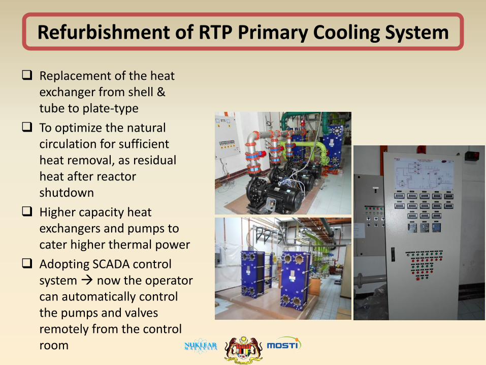
Refurbishment of RTP Primary Cooling System
Replacement of the heat exchanger from shell & tube to plate-type
To optimize the natural circulation for sufficient heat removal, as residual heat after reactor shutdown
Higher capacity heat exchangers and pumps to cater higher thermal power
Adopting SCADA control system now the operator can automatically control the pumps and valves remotely from the control room

Refurbishment of RTP Instrumentation and Control
• There are an increased in system instability, errors on system’s indicators , non-functional functions, intermittent signals which had led to the increment of downtime and maintenance time after 25 years of operation.
• Maintenance of the console faced a major difficulty due to ageing factors, spare parts procurements and lack of support by the manufacturer.
• The process of tender for the new console is still ongoing and expected to start by 2012.

Quality Assurance Programme
• Adopted from the SS50C/SG-Q • Covers :
– the entire operations and maintenance of the reactor,
– the management review, – the control of modifications of
installations, – control of experimental and
testing programmes and treatment,
– storage and transport of fissile and radioactive material.
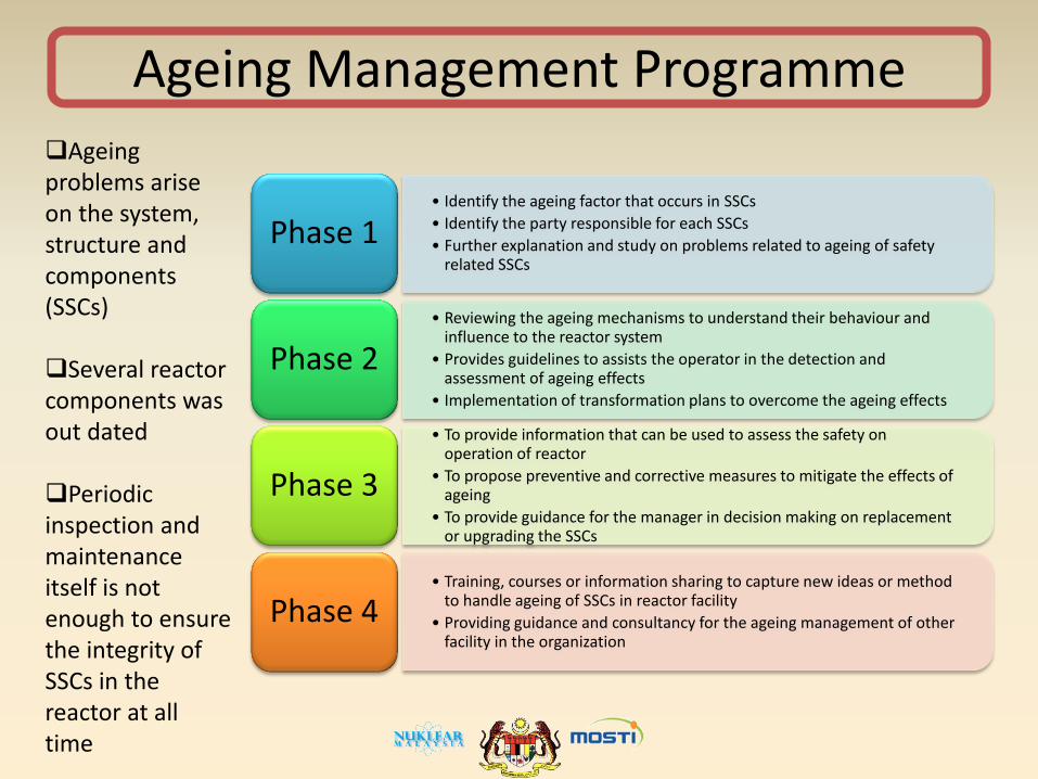
Ageing Management Programme
• Identify the ageing factor that occurs in SSCs
• Identify the party responsible for each SSCs
• Further explanation and study on problems related to ageing of safety related SSCs
Phase 1
• Reviewing the ageing mechanisms to understand their behaviour and influence to the reactor system
• Provides guidelines to assists the operator in the detection and assessment of ageing effects
• Implementation of transformation plans to overcome the ageing effects
Phase 2
• To provide information that can be used to assess the safety on operation of reactor
• To propose preventive and corrective measures to mitigate the effects of ageing
• To provide guidance for the manager in decision making on replacement or upgrading the SSCs
Phase 3
• Training, courses or information sharing to capture new ideas or method to handle ageing of SSCs in reactor facility
• Providing guidance and consultancy for the ageing management of other facility in the organization
Phase 4
Ageing problems arise on the system, structure and components (SSCs)
Several reactor components was out dated
Periodic inspection and maintenance itself is not enough to ensure the integrity of SSCs in the reactor at all time

Neutronics & Thermal Hydraulic Analysis
ANALYSIS
• 2MW- RING-119FE- Central flux trap- Natural convection flow (upward)
• 3MW- RING-119FE- Central flux trap- Natural convection flow (upward)
• 3MW- RING-119FE- Central flux trap- Forced flow (Downward)
Thermal Hydraulic • Using PARET and RELAP • PARET to calculate
coolant and fuel temperature
• RELAP to deliver flowrate in PARET calculation
Neutronics • Using MCNP • MCNP to calculate keff,
power distribution, peaking factor, shutdown margin

Neutronic Analysis MCNP core configuration with 119 FE and central flux trap 119 fuel element, 8.5% standard TRIGA kcode: 1000000 nps & 1000 histories of neutron error <0.01 neutron flux & power normalization constants for 2MW: F = 1.53E+17 (1/k_eff) , P = 2.45E+4 (1/k_eff)

Neutronic Analysis
Reactivity results:
i. Keff : 1.06584
ii. Shutdown margin: (CR worth – core reactivity excess must be positive)
iii. Neutron flux: (2MW)
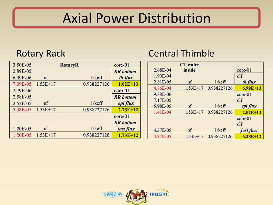
Axial Power Distribution
Rotary Rack Central Thimble

Power and PPF Distribution in Fuel Rings- Radial
Histogram correspond to power and peaking factor
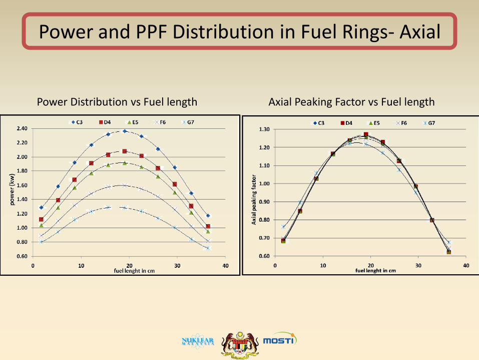
Power and PPF Distribution in Fuel Rings- Axial
Power Distribution vs Fuel length Axial Peaking Factor vs Fuel length
Thermal Hydraulic Analysis
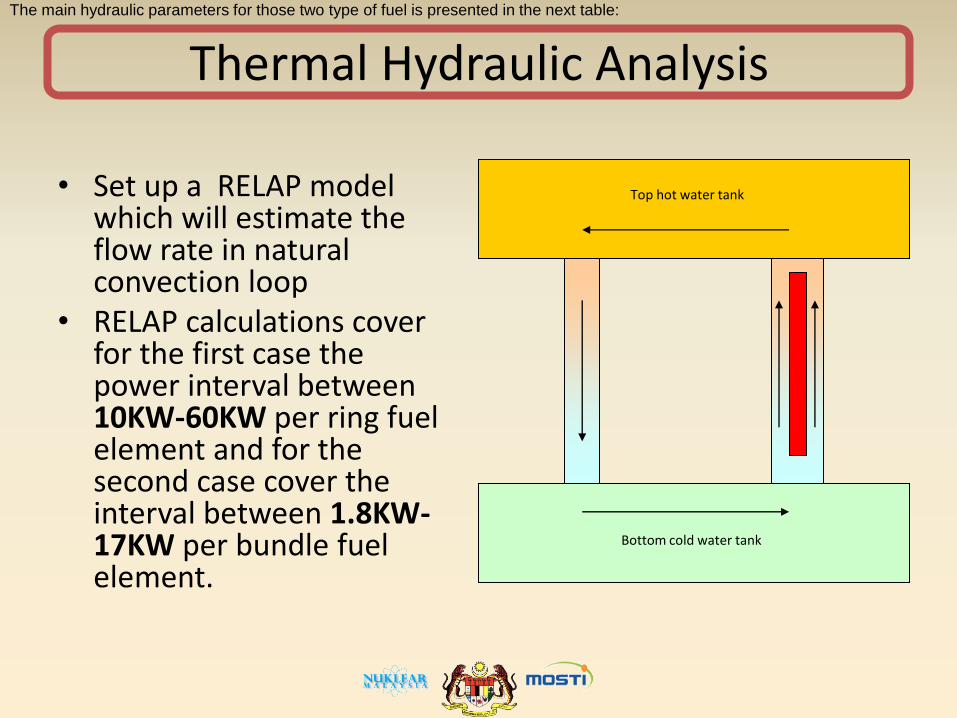
• Set up a RELAP model which will estimate the flow rate in natural convection loop
• RELAP calculations cover for the first case the power interval between 10KW-60KW per ring fuel element and for the second case cover the interval between 1.8KW-17KW per bundle fuel element.
The main hydraulic parameters for those two type of fuel is presented in the next table:
Bottom cold water tank
Top hot water tank

Hydraulic Parameters
Dim. (cm; cm2; cm3) Ring fuel element
Bundle fuel element
Fuel radius 1.8224 0.6467
Gap radius 1.8262 0.6473 Clad radius 1.8770 0.6883 Water channel radius 2.3000 0.9201 Lateral clad area 449.33 164.77 Fuel volume/FE 397.52 50.058 Flow area/FE 5.6250 1.1458 Fuel height 38.100 38.100 Clad xsection area 11.068 1.4883
The main hydraulic parameters for two types of fuel
Ring reactor natural convection flow rate
0
50
100
150
200
250
300
350
0 10000 20000 30000 40000 50000 60000 70000
P/FE (W)
Flo
w R
ate
(K
g/m
2/s)
Bundle reactor natural convection flow rate
0
50
100
150
200
250
300
350
0 2000 4000 6000 8000 10000 12000
P/FE (W)
Flo
w r
ate
(kg
/m2/s
)

PARET Analysis
• The three main parameters in SAR are: – Total flow rate of the core 6.7 kg/s – Maximum fuel temperature 415C – Another derived parameter from above two
is the water temperature evolution for the average channel. (32C-67C SAR prediction)
• The flow rate for the average channel (P=12500W : Flow area 450cm2) was determined in above calculations using RELAP5 (7.1kg/s),
• This is in very good agreement with original SAR .
• In order to calculate all these parameters, two PARET inputs has been made: – Average cannel – Maximum channel
Restrictions:
Maximum fuel temperature -
900C (SAR)
Maximum DNB Heat Flux –
127W/cm2 (SAR, natural
convection)
Maximum Clad temperature –
400C (SAR, However
temperature of the clad is
situated under DNB Heat flux
due to corrosion problems
<150 C)
Exit coolant temperature <
90C (avoiding boiling and
flow instabilities)

PARET for SAR using 80FE-average
AXIAL LIQUID(VAPOR) CLAD SURFACE FUEL SURFACE FUEL CENTER MASS FLOW MODERATOR NODE TEMPERATURE TEMPERATURE TEMPERATURE TEMPERATURE RATE REGIME (DEG. C) (DEG. C) (DEG. C) (DEG. C) KG/S*M**2) 1 32.0000 118.0678 160.6136 269.5145 155.00 LIQUID 2 34.4281 118.9735 160.5193 269.4202 155.00 NUCLEATE BOIL. 3 36.0468 118.9735 160.5193 269.4202 155.00 NUCLEATE BOIL. 4 37.6641 118.9735 160.5193 269.4202 155.00 NUCLEATE BOIL. 5 39.2814 118.9735 160.5193 269.4202 155.00 NUCLEATE BOIL. 6 40.8987 118.9735 160.5193 269.4202 155.00 NUCLEATE BOIL. 7 42.5151 118.9735 160.5193 269.4202 155.00 NUCLEATE BOIL. 8 44.1309 118.9735 160.5193 269.4202 155.00 NUCLEATE BOIL. 9 45.7468 118.9735 160.5193 269.4202 155.00 NUCLEATE BOIL. 10 47.3623 118.9735 160.5193 269.4202 155.00 NUCLEATE BOIL. 11 48.9766 118.9735 160.5193 269.4202 155.00 NUCLEATE BOIL. 12 50.5909 118.9735 160.5193 269.4202 155.00 NUCLEATE BOIL. 13 52.2052 118.9735 160.5193 269.4202 155.00 NUCLEATE BOIL. 14 53.8182 118.9735 160.5193 269.4202 155.00 NUCLEATE BOIL. 15 55.4309 118.9735 160.5193 269.4202 155.00 NUCLEATE BOIL. 16 57.0435 118.9735 160.5193 269.4202 155.00 NUCLEATE BOIL. 17 58.6556 118.9735 160.5193 269.4202 155.00 NUCLEATE BOIL. 18 60.2666 118.9735 160.5193 269.4202 155.00 NUCLEATE BOIL. 19 61.8775 118.9735 160.5193 269.4202 155.00 NUCLEATE BOIL. 20 63.4885 118.9735 160.5193 269.4202 155.00 NUCLEATE BOIL. 21 65.9024 118.9735 160.5193 269.4202 155.00 NUCLEATE BOIL.
Paret main output parameters for SAR 80FE Ring reactor Average channel Natural Convection (SAR water exit 67C) Power =1MW Subchannel power 12500w PPF=1. APF=1. CPF=1. Qmax.=27.01W/cm2 Results: Exit temperature 66C very good agreement with SAR

PARET for SAR using 80FE-maximum
AXIAL LIQUID(VAPOR) CLAD SURFACE FUEL SURFACE FUEL CENTER MASS FLOW MODERATOR
NODE TEMPERATURE TEMPERATURE TEMPERATURE TEMPERATURE RATE REGIME
(DEG. C) (DEG. C) (DEG. C) (DEG. C) (KG/S*M**2)
1 32.0000 119.2542 173.9933 316.5068 185.00 LIQUID
2 34.4840 119.7516 174.4675 317.8899 185.00 NUCLEATE BOIL.
3 36.3857 120.1299 181.9502 343.9947 185.00 NUCLEATE BOIL.
4 38.5043 120.4452 188.5389 367.0274 185.00 NUCLEATE BOIL.
5 40.8133 120.7045 194.1991 386.8447 185.00 NUCLEATE BOIL.
6 43.2826 120.9142 198.9373 403.4532 185.00 NUCLEATE BOIL.
7 45.8853 121.0806 202.8013 417.0093 185.00 NUCLEATE BOIL.
8 48.5921 121.2033 205.7076 427.2119 185.00 NUCLEATE BOIL.
9 51.3749 121.2880 207.7450 434.3677 185.00 NUCLEATE BOIL.
10 54.2054 121.3345 208.8716 438.3258 185.00 NUCLEATE BOIL.
11 57.0563 121.3452 209.1316 439.2391 185.00 NUCLEATE BOIL.
12 59.8993 121.3184 208.4817 436.9557 185.00 NUCLEATE BOIL.
13 62.7060 121.2521 206.8781 431.3228 185.00 NUCLEATE BOIL.
14 65.4480 121.1504 204.4499 422.7962 185.00 NUCLEATE BOIL.
15 68.0986 121.0063 201.0652 410.9171 185.00 NUCLEATE BOIL.
16 70.6290 120.8207 196.8081 395.9878 185.00 NUCLEATE BOIL.
17 73.0112 120.5861 191.5880 377.6996 185.00 NUCLEATE BOIL.
18 75.2185 120.3032 185.5302 356.5045 185.00 NUCLEATE BOIL.
19 77.2219 119.9582 178.4963 331.9376 185.00 NUCLEATE BOIL.
20 78.9952 119.5442 170.5626 304.2928 185.00 NUCLEATE BOIL.
21 81.2667 119.0392 161.6237 273.2471 185.00 NUCLEATE BOIL.
Paret main output parameters for SAR 80FE Ring reactor Maximum channel Natural Convection(SAR max fuel temperature 415C) Power =1MW Subchannel power 26500W PPF=1.7 APF=1.25 CPF=2.12 Qmax.=56.7
Results: Maximum exit temperature=81.2C Maximum clad temperature=121.3C Maximum fuel center temperature=439C Nucleate boil
PARET for 2MW using 119FE-maximum
AXIAL LIQUID(VAPOR) CLAD SURFACE FUEL SURFACE FUEL CENTER MASS FLOW MODERATOR
NODE TEMPERATURE TEMPERATURE TEMPERATURE TEMPERATURE RATE REGIME
(DEG. C) (DEG. C) (DEG. C) (DEG. C) (KG/S*M**2)
1 32.0000 119.6941 193.5664 386.3688 220.00 LIQUID
2 34.8098 120.7096 194.3122 387.2408 220.00 NUCLEATE BOIL.
3 36.9605 121.1443 204.3035 422.2821 220.00 NUCLEATE BOIL.
4 39.3571 121.5065 213.1046 453.2033 220.00 NUCLEATE BOIL.
5 41.9685 121.8043 220.6677 479.8103 220.00 NUCLEATE BOIL.
6 44.7610 122.0452 227.0002 502.1104 220.00 NUCLEATE BOIL.
7 47.7045 122.2364 232.1653 520.3131 220.00 NUCLEATE BOIL.
8 50.7651 122.3773 236.0506 534.0134 220.00 NUCLEATE BOIL.
9 53.9115 122.4747 238.7747 543.6226 220.00 NUCLEATE BOIL.
10 57.1119 122.5281 240.2811 548.9377 220.00 NUCLEATE BOIL.
11 60.3345 122.5404 240.6287 550.1642 220.00 NUCLEATE BOIL.
12 63.5491 122.5097 239.7597 547.0979 220.00 NUCLEATE BOIL.
13 66.7206 122.4334 237.6157 539.5337 220.00 NUCLEATE BOIL.
14 69.8204 122.3167 234.3692 528.0838 220.00 NUCLEATE BOIL.
15 72.8152 122.1511 229.8445 512.1328 220.00 NUCLEATE BOIL.
16 75.6748 121.9379 224.1544 492.0865 220.00 NUCLEATE BOIL.
17 78.3662 121.6684 217.1785 467.5316 220.00 NUCLEATE BOIL.
18 80.8599 121.3433 209.0852 439.0761 220.00 NUCLEATE BOIL.
19 83.1232 120.9469 199.6911 406.0970 220.00 NUCLEATE BOIL.
20 85.1266 120.4714 189.1001 368.9911 220.00 NUCLEATE BOIL.
21 87.6916 119.8912 177.1749 327.3282 220.00 NUCLEATE BOIL.
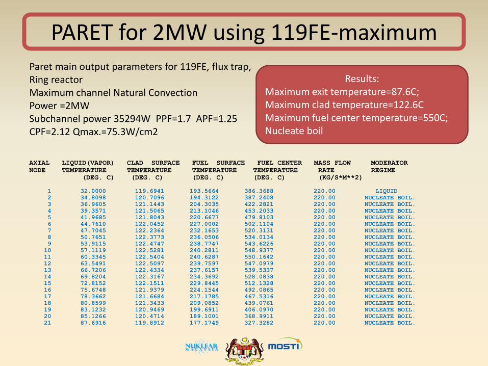
Paret main output parameters for 119FE, flux trap, Ring reactor Maximum channel Natural Convection Power =2MW Subchannel power 35294W PPF=1.7 APF=1.25 CPF=2.12 Qmax.=75.3W/cm2
Results: Maximum exit temperature=87.6C; Maximum clad temperature=122.6C Maximum fuel center temperature=550C; Nucleate boil

PARET for 3MW using 119FE-maximum, natural convection
AXIAL LIQUID(VAPOR) CLAD SURFACE FUEL SURFACE FUEL CENTER MASS FLOW MODERATOR
NODE TEMPERATURE TEMPERATURE TEMPERATURE TEMPERATURE RATE REGIME
(DEG. C) (DEG. C) (DEG. C) (DEG. C) (KG/S*M**2)
1 32.0000 121.3068 231.6154 520.8190 260.00 NUCLEATE BOIL.
2 35.5663 122.2544 232.6584 522.0514 260.00 NUCLEATE BOIL.
3 38.2951 122.7800 247.5188 574.4868 260.00 NUCLEATE BOIL.
4 41.3369 123.2179 260.6150 620.7632 260.00 NUCLEATE BOIL.
5 44.6491 123.5780 271.8730 660.5869 260.00 NUCLEATE BOIL.
6 48.1923 123.8692 281.3017 693.9669 260.00 NUCLEATE BOIL.
7 51.9254 124.1003 288.9937 721.2155 260.00 NUCLEATE BOIL.
8 55.8068 124.2707 294.7806 741.7247 260.00 NUCLEATE BOIL.
9 59.7963 124.3885 298.8384 756.1101 260.00 NUCLEATE BOIL.
10 63.8539 124.4530 301.0825 764.0674 260.00 NUCLEATE BOIL.
11 67.9381 124.4678 301.6003 765.9036 260.00 NUCLEATE BOIL.
12 72.0104 124.4307 300.3057 761.3130 260.00 NUCLEATE BOIL.
13 76.0294 124.3385 297.1119 749.9888 260.00 NUCLEATE BOIL.
14 79.9552 124.1973 292.2762 732.8480 260.00 NUCLEATE BOIL.
15 83.7472 123.9971 285.5373 708.9696 260.00 NUCLEATE BOIL.
16 87.3670 123.7394 277.0642 678.9623 260.00 NUCLEATE BOIL.
17 90.7740 123.4136 266.6788 642.2086 260.00 NUCLEATE BOIL.
18 93.9279 123.0206 254.6334 599.6198 260.00 NUCLEATE BOIL.
19 96.7926 122.5414 240.6577 550.2665 260.00 NUCLEATE BOIL.
20 99.3246 121.9665 224.9096 494.7461 260.00 NUCLEATE BOIL.
21 102.5691 121.2651 207.1906 432.4206 260.00 NUCLEATE BOIL.
Paret main output parameters for 119FE, flux trap, Ring reactor, Maximum channel Natural Convection Power =3MW, Subchannel power 53941W PPF=1.7 APF=1.25 CPF=2.12 Qmax.=113.42W/cm2
Results Maximum exit temperature=102.6C; Maximum clad temperature=124.4C Maximum fuel center temperature=765C; Nucleate boil
PARET for 3MW using 119FE-maximum, forced flow
AXIAL LIQUID(VAPOR) CLAD SURFACE FUEL SURFACE FUEL CENTER MASS FLOW MODERATOR
NODE TEMPERATURE TEMPERATURE TEMPERATURE TEMPERATURE RATE REGIME
(DEG. C) (DEG. C) (DEG. C) (DEG. C) (KG/S*M**2)
1 36.6163 76.5765 170.8851 418.0887 -4000.00 LIQUID
2 36.3847 83.2674 193.6713 483.0644 -4000.00 LIQUID
3 36.2073 89.2665 214.0053 540.9733 -4000.00 LIQUID
4 36.0096 94.5630 231.9602 592.1085 -4000.00 LIQUID
5 35.7940 99.1223 247.4174 636.1313 -4000.00 LIQUID
6 35.5632 102.9438 260.3763 673.0415 -4000.00 LIQUID
7 35.3199 106.0603 270.9536 703.1754 -4000.00 LIQUID
8 35.0667 108.3967 278.9067 725.8508 -4000.00 LIQUID
9 34.8063 110.0212 284.4712 741.7429 -4000.00 LIQUID
10 34.5413 110.8932 287.5227 750.5076 -4000.00 LIQUID
11 34.2742 111.0440 288.1765 752.4798 -4000.00 LIQUID
12 34.0077 110.4321 286.3071 747.3144 -4000.00 LIQUID
13 33.7445 109.0157 281.7891 734.6660 -4000.00 LIQUID
14 33.4872 106.8993 274.9782 715.5500 -4000.00 LIQUID
15 33.2384 103.9683 265.5085 688.9408 -4000.00 LIQUID
16 33.0007 100.2919 253.6167 655.5148 -4000.00 LIQUID
17 32.7768 95.7931 239.0583 614.5880 -4000.00 LIQUID
18 32.5693 90.5799 222.1928 567.1792 -4000.00 LIQUID
19 32.3807 84.5406 202.6568 512.2656 -4000.00 LIQUID
20 32.2139 77.7491 180.6922 450.5287 -4000.00 LIQUID
21 32.0000 70.0893 156.0149 381.2449 -4000.00 LIQUID
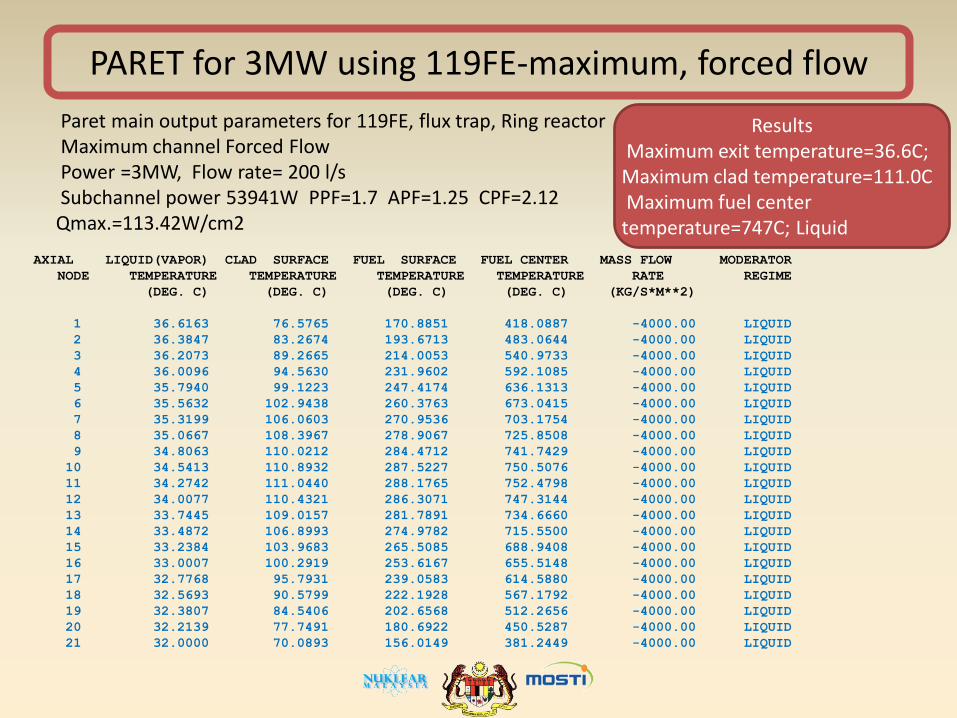
Paret main output parameters for 119FE, flux trap, Ring reactor Maximum channel Forced Flow Power =3MW, Flow rate= 200 l/s Subchannel power 53941W PPF=1.7 APF=1.25 CPF=2.12 Qmax.=113.42W/cm2
Results Maximum exit temperature=36.6C; Maximum clad temperature=111.0C Maximum fuel center temperature=747C; Liquid

Conclusion
• The safety approaches that were implemented for RTP has ensured the prolong operations and safety of the reactor.
• The introduction of Ageing Management Programme has contributed very significantly towards to enhance the safe operation of the reactor and increase the efficiency of every system in RTP.
• The reactor instrumentation and control upgrading project that is expected to begin in 2012 will become the stepping stone for RTP to provide a continuous utilization in various field.
• The RTP upgrading work continues by taking into accounts on the expert recommendation and safety assessment of the reactor.
• The objective of increasing the human capability and capacity building in the sense of to develop expertises in Reactor Physics, Thermal Hydraulic, Instrumentation & Cont was achieved through the upgrading exercises

Last but not least..
• Highly appreciation to the person that contribute into this presentation material and work

THANK YOU