lay cii - ir.unimas.my of a single storey house using steel... · sarawak dengan syarat-syarat...
TRANSCRIPT
LAY ci"i
ý
º
mm I I J-! j
DESIGN OF A SINGLE STOREY HOUSE USING STEEL STRUCTURAL ELEMENTS
Sitihanafiah Binti Ruasin
TA 684 Bachelor of Engineering with Honours S623 (Civil Engineering) 2006 2006
Universiti Malaysia Sarawak
fk
BORANG PENYERAHAN LAPORAN PROJEK TAHUN AKHIR
Judul: DESIGN OF A SINGLE STOREY HOUSE USING STEEL STRUCTURAL ELEMENTS
SESI PENGAJIAN: 2002-2006
Saya SITIHANAFIAH BINTI RUASIN
(HURUF BESAR)
mengaku membenarkan tesis ini disimpan di Pusat Khidmat Maklumat Akademik, Universiti Malaysia Sarawak dengan syarat-syarat kegunaan seperti berikut:
I. Hakmilik kertas projek adalah di bawah nama penulis melainkan penulisan sebagai projek bersama dan dibiayai oleh UNIMAS, hakniiliknya adalah kepunyaan UNIMAS.
2. Naskhah salinan di dalam bentuk kertas atau mikro hanya boleh dibuat dengan kebenaran bertulis daripada penulis.
3. Pusat Khidmat Maklumat Akademik, UNIMAS dibenarkan membuat salinan untuk pengajian mereka. 4. Kertas projek hanya botch diterbitkan dengan kebenaran penulis. Bayaran royalti adalah mengikut kadar
yang dipersetujui kelak. 5. * Saya membenarkan/tidak membenarkan Perpustakaan membuat salinan kertas projek ini sebagai bahan
pertukaran di antara institusi pengajian tinggi. 6. ** Sila tandakan ( X ) di mana kotak yang berkenaan
I
ýý
0
SULIT
TERHAD
TIDAK TERHAD
(Mengandungi maklumat yang berdarjah keselamatan atau kepentingan Malaysia seperti yang termaktub di dalam AKTA RAHSIA RASMI 1972).
(Mengandungi maklumat TERHAD yang telah ditentukan oleh organisasi/ hadan di mana penyelidikan dijalankan).
(TANDATANGAN PENULIS)
Alamat tetap: PETI SURAT 736,
Tarikh:
KG. LOHAN SKIM 2,
89308 RANAU, SABAH
17 NºA7 Zoa. 6
ELIA)
PUAN AZIDA RASHIDI
( Nama Penyelia)
Tarikh: [2 74NI5 9ý&D(ý
CATATAN * Potong yang tidak berkenaan. ** Jika Kertas Projek ini SULZT atau TERHAD, sila lampirkan surat daripada pihak berkuasa/
organisasi berkenaan dengan menyertakan sekali tempoh kertas projek. Ini perlu dikelaskan sebagai SUI IT atau TERHAD.
This final year project attached here;
Title
Author's name
Matric Number
Design of a Single Storey House Using Steel Structural
Elements
Sitihanafiah Binti Ruasin
9110
Has been read and approved by;
ý)- UuK Im(Date)
P. KNIDMAT MAKLUMAT AKADEMIK III'IIII
UNIMAS
ý II11II1 IIIII IIII III 1000165995
Pusat Khidmat Makiumat AKademrjL UMVERSITI MALAYSIA SARAWAK
DESIGN OF A SINGLE STOREY HOUSE USING STEEL STRUCTURAL ELEMENTS
SITIHANAFIAH BINTI RUASIN
This project is submitted in partial fulfillment of the requirements for the degree of Bachelor of Science with Honours
(Civil Engineering)
Faculty of Engineering UNIVERSITY MALAYSIA SARAWAK
2006
ACKNOWLEDGEMENT
Bismillahirrahmanirrahim
Very sincere thanks to my supervisor Puan Azida Rashidi for the support,
guidance, advices, and knowledge that has been given throughout finishing this final
year project. This project will never complete without your guidance and
encouragement.
To my beloved mother and father, very deep thanks from bottom of my heart for
all your support, pray and love that encouraging me. With your support and
encouragement I finally finish this project.
Last but not least, i also would like to thank to my lecturers for all the
knowledge that they have teach me and to all my friend thanks for the kindness in
giving support and help to complete this project.
1
ABSTRACT
This research is about designing a single storey house using steel structural
elements. This research is done by using hand calculation in the analysis and design of
the steel structural member with accordance to BS5950-1: 2000.
Simple design method is used in designing the house. As the general principal of
design is to insure that the structure is capable to sustain the loads through its life span
limit state design principle is applied in the analysis of this project. The member must
satisfy the design criteria such as shear strength, moment capacity, deflection and other
criteria that must take into consideration.
The scope of this study is only concentrating in designing the steel beam,
column and column baseplate which there is no reinforced concrete design included in
the analysis and design. This study only considering dead load and imposed load and
also only considering hot rolled section.
The result of this research shows that the proposed member size is adequate
according to design code BS 5950: Part 1 - 2000. UB 127x67x13, UB 203x102x23, UB
305x127x48 and UB 305x127x42 were found adequate sizes for the beams howeverUB
305x 127x48 and UB 305x 127x42 is quite large; which is not suitable for the single
storey house. Column size UC 152x152x23 and column baseplate size 250x250xl5mm
were found adequate for the single storey house construction.
The feasibility of using steel in residential house construction also discussed in
this study.
ii
ABSTRAK
Kajian ini adalah berkenaan dengan merekabentuk rumah setingkat dengan
menggunakan bahan keluli. Analisis dan rekabentuk rumah setingkat ini dilakukan
dengan menggunakan kaedah penggiraan tanpa menggunakan sebarang perisian
komputer tetapi berpandukan kod rekabentuk struktur keluli BS5950 -1: 2000.
Kaedah rekabentuk yang digunakan dalam kajian ini ialah 'Simple design
method'. Prinsip umum dalam rekabentuk bangunan adalah untuk memastikan struktur
bangunan dapat menampung beban yang ditanggung. Bahan struktur keluli yang
digunakan mesti menepati criteria yang ditentukan didalam kod rekabentuk. Ruang
lingkup kajian ini hanya memfokuskankan rekabentuk rasuk, tiang dan tapak tiang dan
tiada rekabentuk konkrit prategasan dilakukan dalam kajian ini. Limitasi kajian ini juga
hanya mempertimbangkan beban mati (dead load) dan beban hidup (live load) dan
bahan struktur keluli yang dibuncangkan hanya 'hot rolled section'.
Berdasarkan kepada kajian, didapati saiz rasuk yang dicadangkan iaitu UB
127x67x13, UB 203x102x23, UB 305x127x48 and UB 305x127x42 menepati standard
kod rekabentuk struktur keluli. Walaubagimanapun didapati bahawa UB 305x127x48
and UB 305x127x42 adalah saiz yang kurang sesuai digunakan kerana terlalu besar. UC
152x152x23 untuk tiang dan tapak tiang saiz 250mmx250mmx15mm adalah sesuai.
Selain daripada analisis dan rekabentuk yang telah dijalankan, kajian ini juga
merangkumi kajian terhadap kebarangkalian dan kebolehan struktur bahan keluli
sebagai bahan dalam pembinaan rumah.
111
Pusal Khidml Maklumlc Akaacmlk UN1 VERS 1'TI MALAYSIA SARAWAIC.
LIST OF CONTENTS
ACKNOWLEDGEMENT
ABSTRACT
ABSTRAK
LIST OF CONTENT
LIST OF TABLES
LIST OF FIGURES
NOTATIONS
CHAPTER1: INTRODUCTION
1.1 Introduction
1.2 Background of study
1.3 Scope of study
1.4 Significant of study
1.5 Objective
1.6 Conclusion
CHAPTER 2: LITERATURE REVIEW
2.1 Introduction
2.2 Steel background
2.3 Design method 2.3.1 Simple design
2.3.2 Rigid design
2.3.3 Semi rigid design
2.4 Loading
2.5 Factor of safety
2.6 Design of structural member procedure
2.6.1 Initial section selection
1
ii
iii
iv
Vll
Vll
ix
1
1
3
4
5
6
7
7
8
8
9
9
9
10
10
12
iv
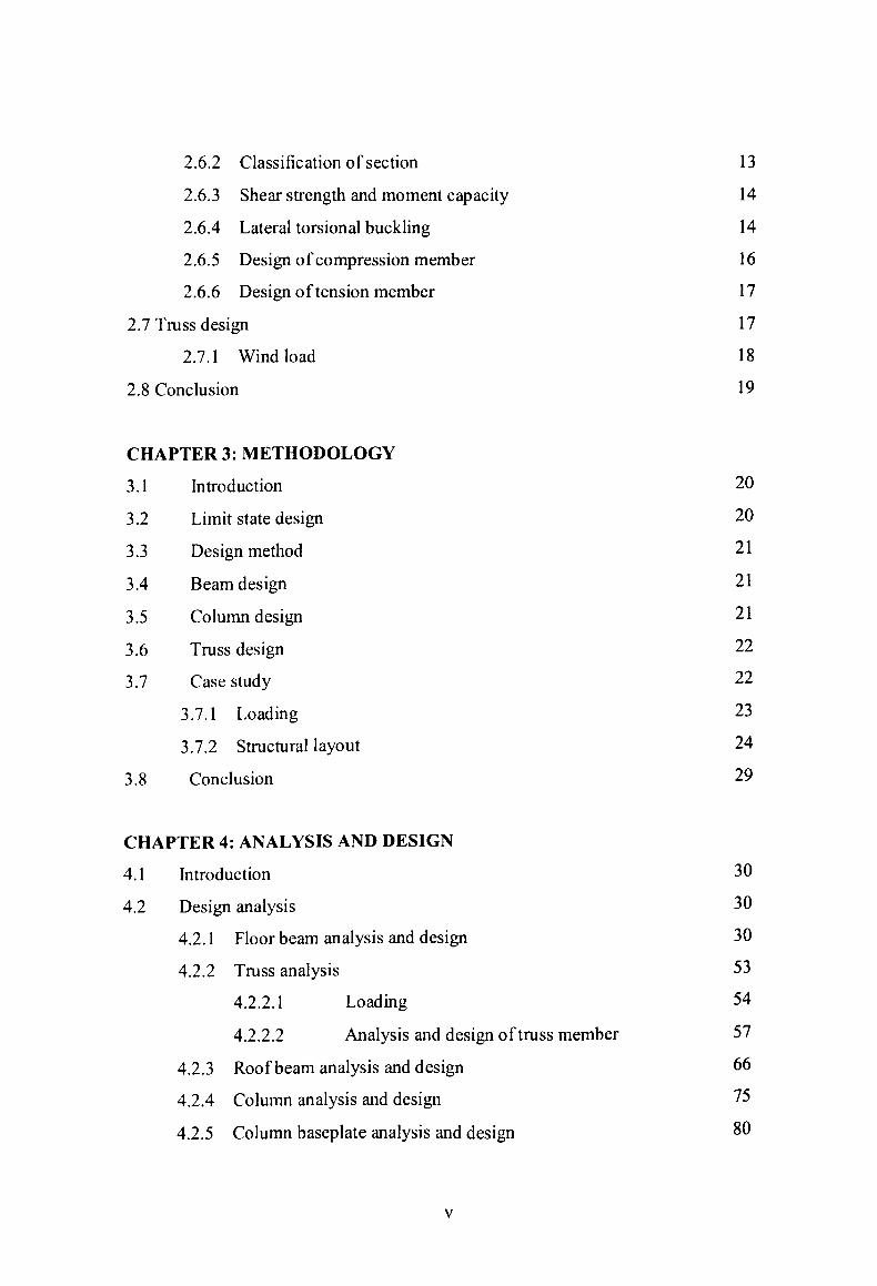
2.6.2 Classification of section 2.6.3 Shear strength and moment capacity
2.6.4 Lateral torsional buckling
2.6.5 Design of compression member
2.6.6 Design of tension member
2.7 Truss design
2.7.1 Wind load
2.8 Conclusion
CHAPTER 3: METHODOLOGY
3.1 Introduction
3.2 Limit state design
3.3 Design method
3.4 Beam design
3.5 Column design
3.6 Truss design
3.7 Case study
3.7.1 Loading
3.7.2 Structural layout
3.8 Conclusion
CHAPTER 4: ANALYSIS AND DESIGN
4.1 Introduction
4.2 Design analysis
4.2.1 Floor beam analysis and design
4.2.2 Truss analysis
4.2.2.1 Loading
4.2.2.2 Analysis and design of truss member
4.2.3 Roof beam analysis and design
4.2.4 Column analysis and design
4.2.5 Column baseplate analysis and design
13
14
14
16
17
17
18
19
20
20
21
21
21
22
22
23
24
29
30
30
30
53
54
57
66
75
80
V
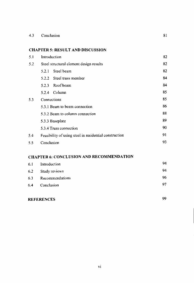
4.3 Conclusion 81
CHAPTER 5: RESULT AND DISCUSSION
5.1 Introduction 82
5.2 Steel structural element design results 82
5.2.1 Steel beam 82
5.2.2 Steel truss member 84
5.2.3 Roof beam 84
5.2.4 Column 85
5.3 Connections 85
5.3.1 Beam to beam connection 86
5.3.2 Beam to column connection 88
5.3.3 Baseplate 89
5.3.4 Truss connection 90
5.4 Feasibility of using steel in residential construction 91
5.5 Conclusion 93
CHAPTER 6: CONCLUSION AND RECOMMENDATION
6.1 Introduction
6.2 Study reviews
6.3 Recommendations
6.4 Conclusion
94
94
96
97
REFERENCES 99
vi
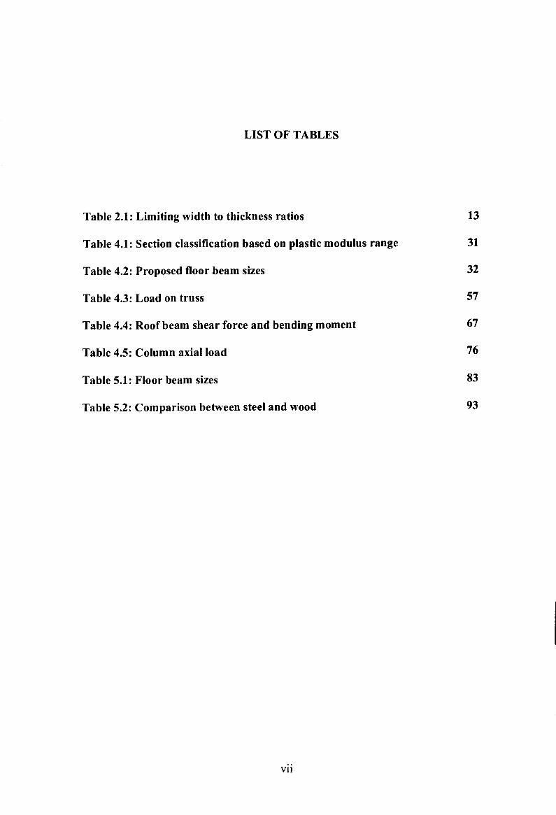
LIST OF TABLES
Table 2.1: Limiting width to thickness ratios 13
Table 4.1: Section classification based on plastic modulus range 31
Table 4.2: Proposed floor beam sizes 32
Table 4.3: Load on truss 57
Table 4.4: Roof beam shear force and bending moment 67
Table 4.5: Column axial load 76
Table 5.1: Floor beam sizes 83
Table 5.2: Comparison between steel and wood 93
vii
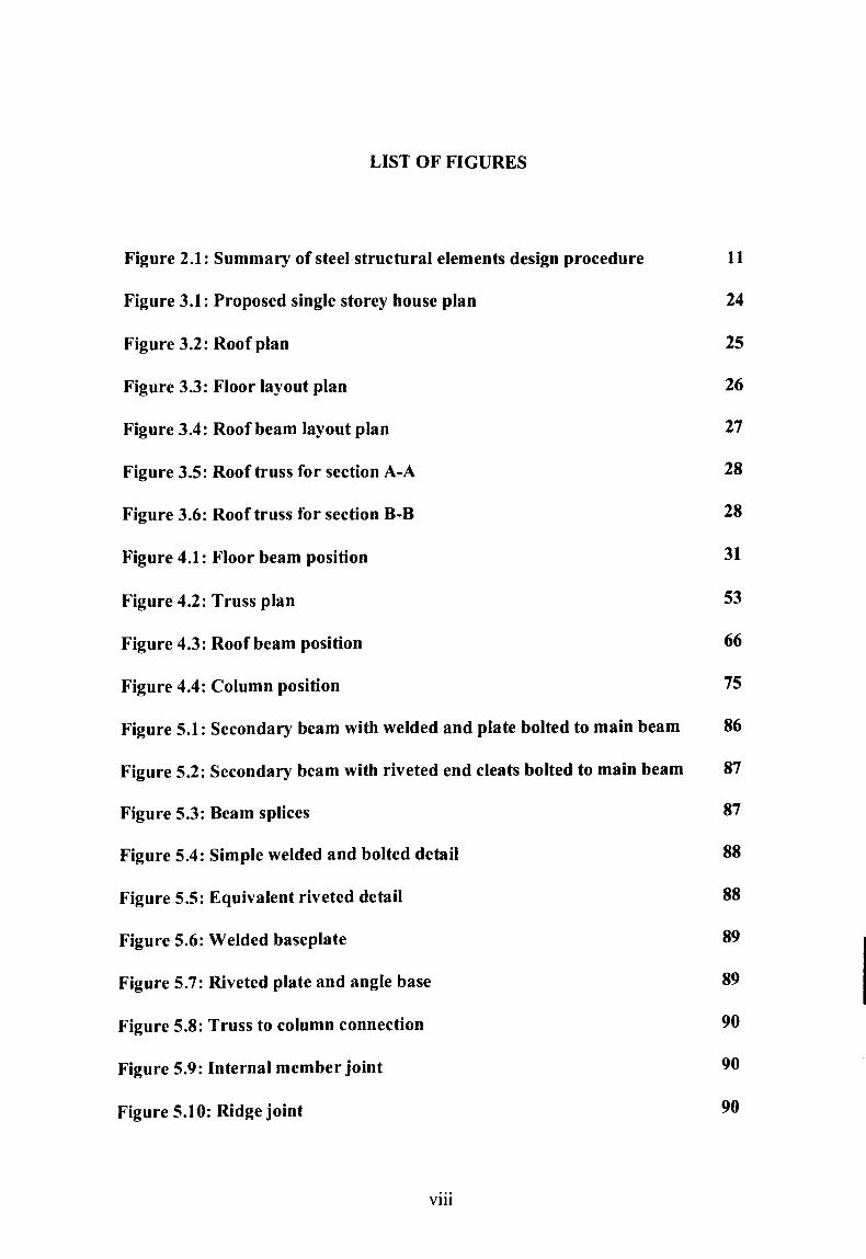
LIST OF FIGURES
Figure 2.1: Summary of steel structural elements design procedure 11
Figure 3.1: Proposed single storey house plan 24
Figure 3.2: Roof plan 25
Figure 3.3: Floor layout plan 26
Figure 3.4: Roof beam layout plan 27
Figure 3.5: Roof truss for section A-A 28
Figure 3.6: Roof truss for section B-B 28
Figure 4.1: Floor beam position 31
Figure 4.2: Truss plan 53
Figure 4.3: Roof beam position 66
Figure 4.4: Column position 75
Figure 5.1: Secondary beam with welded and plate bolted to main beam 86
Figure 5.2: Secondary beam with riveted end cleats bolted to main beam 87
Figure 5.3: Beam splices 87
Figure 5.4: Simple welded and bolted detail 88
Figure 5.5: Equivalent riveted detail 88
Figure 5.6: Welded baseplate 89
Figure 5.7: Riveted plate and angle base 89
Figure 5.8: Truss to column connection 90
Figure 5.9: Internal member joint 90
Figure 5.10: Ridge joint 90
viii
NOTATIONS
A - Area of section
Abe - Effective area of baseplate
Ag - Gross sectional area of steel section
A,, - Shear area
B - Breadth of section
b - Outstand of flange
c - Largest perpendicular distance from the edge of the effective
portion of the baseplate to the face of the column cross-section
D - Depth of section
d - Depth of web
E - Modulus of elasticity
Fc - Ultimate applied axial load
IX, Iy - Second moment area about the major and minor axes
L - Actual length
Le - Effective length
M - Design moment or large end moment
Mb - Buckling resistance moment
MC - Moment capacity
MCX, MCy - Moment capacity of section about the major and minor axes in
the absence of axial load
ix
MX - Maximum major axis moment
MLT - Maximum major axis moment in the segment between restraint
against lateral torsional buckling
mi. - Equivalent uniform moment factor for lateral torsional buckling
P,, - Shear capacity of a section
PC - Compressive strength of steel
Pb - Bending dtrength of steel
Py - Design strength of steel
pyE, - Design strength of baseplate
r,, ry - Radius of gyration of a member about its major and minor axes
Sx, Sy - Plastic modulus about major and mionr axes T - Thickness of flange
t - Thickness of web
tp - Thickness of baseplate
u - Buckling parameter of the section
x - Torsional index of section
Z,, Zy - Elastic modulus about major and minor axes
n - Slenderness factor for beam
ßW - A Ratio for lateral torsional buckling
k - Slenderness ratio
- Equivalent slenderness ratio
w - Pressure under the baseplate
X
CHAPTER 1
INTRODUCTION
1.1 Introduction
This chapter discussed the introduction to the project that had been carried out.
The scope of study, objectives of the study and the significant of study are included in
this chapter.
1.2 Background of study
Building construction is the erection of various types of materials to form
building. There were stages that should be followed to construct any projects. Design
stage is a part of it and can be said as the most critical and important stage whereby the
design of the structure will be performed and analysis will take place to confirm that the
design is adequate for construction.
1
Designing is an important stage that required to be satisfactory and acceptable
by the clients and surely by engineers in order to produce a safe structure. Design
process is both creative and technical and requires a fundamental knowledge of material
properties and the laws of mechanics which govern material response (R. C. Hibbeler,
2002). Good and well designed project produce good quality of work and product
besides reduce the project cost.
Analysis is part of the design process but only take place after the basic form of
the structure has been decided. A particular structure will be analyzed or investigated to
determine the distribution of its force throughout the various members that make up that
structure, determine the distribution of stress and other required calculation to insure the
design is adequate. The analysis of structure is necessary to prove that the structure is
strong enough to support the loads as the aim of it is to get as close as possible to
correct solution in order to avoid the various factors that can affect the structure.
Selection of types of materials that is going to be used must be really taken into
consideration such the properties and the performance of the materials. It is necessary to
know the material's behavior if the safety, reliability and durability are concern.
Although materials that is strong and cheap are desirable for construction but it is really
necessary to examine various factors that can affect the safety and durability of
structure.
2
1.3 Scope of study
The objective of design is to provide the information necessary for the
construction of a single storey house including drawing, plan, detailing of connection
and others. According to Frederick S. Merritt, the ultimate objective of design is
production of drawings or a plan, showing what is going to be constructed, specification
stating what materials and equipment are to be incorporated in the building, and a
construction contract between client and a contractor (1994). But for this study, the
equipment specification and construction are not discussed. Plans are produced to
specify the proposed design of the house that is going to be design.
In this study the scope of the project is limited which is only to design the steel
beam, column and column baseplate. There is no reinforced concrete design involved in
this study. The loads that was taken into consideration is only the dead load and the
imposed load which is defined at clause 2.4.1.2 of BS5950 which mean the wind load is
not affecting the house structure. Only hot rolled formed steel section is considered in
this study.
Inadequate design of any construction project can bring to unsuccessful and
sometimes disastrous product. Through the analysis of this design project study, the
adequacy of design will be achieved. Actually, in the process of designing, several
studies are required before adopting the most suitable structural form for the specified
project.
3
1.4 Significant of study
Design process is involving several of procedure. Even though only the analysis
procedure was discuss in this study but it has create intention that design work must be
really done in proper way as to insure that the structure is safe and anyone that carry out
any building or other construction should aware and responsible to create safety
structure for the end users. Design not only fulfilling the client requirement but also
meeting the cost provided, quality of product and safety beside the time consuming for
the completion of the project.
Some knowledge concerning the behavior of materials is vital if, safe, reliable
and long-lasting structures are result (Derek Seward, 1998). Study on properties of
structural materials gave better understanding of how selection of materials is very
important, through the design process which can affect the structure. Properties such
strength and stiffness of the materials, it's durability, fatigue, brittle fracture and other
properties was really take into consideration. This can be use as guidance in choosing
materials for the structure that is going to be constructed. Thus any failure can be
avoided.
Apart from the analysis and design, this study also see the feasibility of using
steel structural element in residential construction by considering some issue that
promoting steel to become the material for house construction.
4
As the study focus on steel design, it is hope that this study can be used as a
source of reference for future study and perhaps encourages other people who involved
in this industry to deliver better quality of work by do good quality of design project
towards producing good quality of structure.
1.5 Objective
The objective of this study is to analyze and design the residential house. Below
are the main objectives that have to be achieved in this study.
1. To analyze and design the structural elements that commonly used in residential
or domestic construction.
2. To identify the steel structural elements in designing the project study according
to BS 5950: Part 1.
3. To study the detailing and connection of the steel elements in a single storey
house.
4. Determine the feasibility study of using steel for house construction.
5
1.6 Conclusion
This chapter began with the introduction of the design project which indicates
the scope of the study and the objective of this study. The next chapter will discuss
about the theory and other literature review that relevant to this study.
6
CHAPTER 2
LITERATURE REVIEW
2.1 Introduction
This chapter will discuss about the theory, concept and literature reviews that
related with the steel structural elements design and analysis.
2.2 Steel background
Steel is iron alloyed with small amount of carbon. Various types of steel are
produced by varying the percentage of carbon. Besides the quantity of carbon added,
other factors such as the cooling rate influence the properties of steel produced. To
produce consistent and reliable steel for structural purpose quality control are required.
High strength, high fracture toughness, longer fatigue life, high corrosion
resistance and better weldability are the user demands for new constructional steel
(Yuhshi Fukumoto, 1990). The common type of steel used is mild steel because apart
7
from the properties mentioned it is also cheaper. High yield steel is a stronger grade and
commonly used for reinforcing bars in concrete. It has irregular surface pattern to
improve bond in the concrete. There were also some special types of steel for special
purpose such as stainless steel which has high corrosion resistance.
2.3 Design method
British Standard codes of practice for structural steelwork BS5950: Part 1: 2000
`Structural use of steelwork in Building' will be used for the design analysis of the
structural elements. The method for designing will be focused on the limit state design.
The concept of limit state design is to produce a safe and economical structure that
fulfills its required purpose.
In accordance to clause 2.1.2 of BS5950 the design method for building are
carried out by three design methods.
2.3.1 Simple design
In this method, the connection between members is assumed not to
develop moment that affecting either the member and or the whole structure.
The structure is assumed to be pin jointed for analysis. The structure should
8
laterally restrained both in-plane and out-plane to resist horizontal stability and
provide sway stability.
2.3.2 Rigid design
Rigid design is also known as continuous design which elastic and
plastic analysis method can be used for the analysis. The connections are
assumed to be capable resist the moment and forces resulting from the analysis.
2.3.3 Semi-rigid design
This method which also known as semi continuous design may be used
where the connection have some degree of strength and stiffness which means it
can transmit some moment and elastic and plastic analysis.
2.4 Loading
In structural design the loading needs to be estimated for the life span of the
structure.
9
The types of loads carried by structural member are
(i) Dead load from self weight of beam, slabs, finishes and other load that the
beam should be carry.
(ii) Imposed loads from people, fittings, snow on roof and others
(iii) Wind loads mainly purlins and sheeting rails.
The characteristic dead and imposed loads can be obtained from BS 6399: Parts
1 and 3. Wind load should be determined from BS 6399: Part 2 or from CP3: Chapter
V: Part 2. Clause 2.4.1.2 of BS5950 state the principal of loads combination.
2.5 Factor of safety
Clause 2.1.3 of BS 5950: Parts 1 stated that structures should be designed by
considering the limit states which the structure become unfit for their intended use. To
obtain design loading at ultimate limit state the characteristic load is multiplied by a
load factor, yf. For dead load the load factor is 1.4 and for imposed load is 1.6.
2.6 Design of steel structural member procedure
The design of steel structural member procedures is as stated in section 4 of
BS5950: Part 1.
10