development of an extremely robust automotive … · laporan akhir penyelidikan tajuk projek :...
TRANSCRIPT
DEVELOPMENT OF AN EXTREMELY ROBUST AUTOMOTIVE
SUSPENSION SYSTEM USING INTELLIGENT ACTIVE FORCE
CONTROL
(PEMBANGUNAN SISTEM SUSPENSI KENDERAAN LASAK
MENGGUNAKAN KAWALAN DAYA AKTIF PINTAR)
MUSA MAILAH
HISHAMUDDIN JAMALUDDIN
MOHD ZARHAMDY MOHD ZAIN
GIGIH PRIYANDOKO
MOHAMAD AKMAL BAHRAIN ABDUL RAHIM
RESEARCH VOTE NO: 74221
RESEARCH MANAGEMENT CENTRE UNIVERSITI TEKNOLOGI MALAYSIA
2007
UNIVERSITI TEKNOLOGI MALAYSIA
UTM/RMC/F/0024 (1998)
BORANG PENGESAHAN
LAPORAN AKHIR PENYELIDIKAN
TAJUK PROJEK : DEVELOPMENT OF AN EXTREMELY ROBUST AUTOMOTIVE
SUSPENSION SYSTEM USING INTELLIGENT ACTIVE FORCE
CONTROL
Saya _________________________MUSA BIN MAILAH_ ___________________________ (HURUF BESAR)
Mengaku membenarkan Laporan Akhir Penyelidikan ini disimpan di Perpustakaan Universiti Teknologi Malaysia dengan syarat-syarat kegunaan seperti berikut :
1. Laporan Akhir Penyelidikan ini adalah hakmilik Universiti Teknologi Malaysia.
2. Perpustakaan Universiti Teknologi Malaysia dibenarkan membuat salinan untuk tujuan rujukan sahaja.
3. Perpustakaan dibenarkan membuat penjualan salinan Laporan Akhir
Penyelidikan ini bagi kategori TIDAK TERHAD.
4. * Sila tandakan ( / )
SULIT (Mengandungi maklumat yang berdarjah keselamatan atau Kepentingan Malaysia seperti yang termaktub di dalam AKTA RAHSIA RASMI 1972). TERHAD (Mengandungi maklumat TERHAD yang telah ditentukan oleh Organisasi/badan di mana penyelidikan dijalankan). TIDAK TERHAD
TANDATANGAN KETUA PENYELIDIK
PROFESOR MADYA DR. MUSA MAILAH Nama & Cop Ketua Penyelidik Tarikh : 10 APRIL 2007
/
CATATAN : * Jika Laporan Akhir Penyelidikan ini SULIT atau TERHAD, sila lampirkan surat daripada pihak berkuasa/organisasi berkenaan dengan menyatakan sekali sebab dan tempoh laporan ini perlu dikelaskan sebagai SULIT dan TERHAD.
Lampiran 20
iii
DEDICATIONS
To all Intelligent Active Force Control Research Group
(IAFCRG) members – a big thank you for all your
contributions and participation……

iv
ACKNOWLEDGEMENTS
We would like to express our sincere gratitude and appreciation to the
Ministry of Science Technology and Innovation (MOSTI), Malaysia, for providing
the project research grant (Project No.: 03-02-06-0123EA001) and the Universiti
Teknologi Malaysia (UTM) for their full support in terms of accommodating the
research infrastructures and facilities. Special thanks go to Abdul Rahim Mohamad,
Ahmad Faisal and Ahmad Shahrizam from the Systems & Control Laboratory for
their meaningful contribution in assisting some of the works related to this project.
Last but not least to everyone who has in one way or another contributed to the
success of this project.
v
ABSTRACT
This report describes both theoretical and experimental studies of a quarter-car
vehicle suspension system that incorporates a number of control schemes in which a
number of responses or characteristics were rigorously investigated. Particular focus is
on the application of a very practical robust control scheme known as active force
control (AFC) that is expected to render any forms of disturbances on the system to be
effectively compensated. These disturbances are mostly in the form of various modelled
road profiles (terrains) that the unsprung mass (tyre or wheel) comes in direct contact
with and which in turn are transmitted to the sprung mass (body) of the system causing
undesirable vibration or shaking that may cause discomfort to the ‘passenger’. Thus, it is
the main aim of this study to come up with solution/s that can minimise this discomfort
condition (thereby improved the riding comfort) in such a way that the body of the
vehicle shall remain almost indifferent to the introduced disturbances. In other words,
the sprung mass (body) of the vehicle is extremely robust to the vibration or other
external forces. A direct measure would be the significant reduction in the body
acceleration and displacement. Intelligent techniques employing neural network (NN),
adaptive fuzzy logic (AFCL) and their hybrids were value-added contributions that were
deliberately and primarily introduced into the AFC schemes to approximate the virtual
estimated mass of the system that is vital to trigger the AFC mechanism. Indeed,
simulation results have shown the extreme robust nature of the AFC-based schemes embedded
with a number of intelligent methods in countering and nullifying the induced vibration effects
and other adverse conditions. The simulation results were then consequently validated by
experiments conducted on a working prototype which is mechatronically designed and
developed in a laboratory. The body acceleration and displacement of the system were
considerably reduced to more than 70% compared to a passive control system and about 50% to
a closed-loop proportional-integral-derivative (PID) control, thereby exhibiting the robust
performance of the proposed AFC-based methods.
vi
ABSTRAK
Laporan ini menerangkan secara teori dan juga ujikaji terhadap suatu sistem suspensi
kenderaan suku-kereta yang memuatkan beberapa skema kawalan di mana sambutan atau ciri
sistem dikaji secara mendalam. Tumpuan lebih menjurus kepada aplikasi suatu teknik praktikal
yang lasak serta dikenali sebagai kawalan daya aktif (AFC) yang boleh mengakibatkan sebarang
gangguan terhadap sistem dipampas atau dihindarkan dengan amat baik. Gangguan ini
sebahagian besarnya berpunca dari keadaan permukaan jalan di mana ia bersentuhan dengan
jisim tak berspring (tayar atau roda) menyebabkan berlakunya getaran tak diingini pada jisim
berspring (badan) kenderaan dan seterusnya boleh mendatangkan kesan tidak selesa terhadap
pengguna. Maka, adalah menjadi tujuan utama projek ini dirangkakan untuk mencari jalan
penyelesaian terhadap keadaan ketidakselesaan (dengan demikian, meningkatkan keselesaan
pemanduan) begitu rupa sehingga badan sistem kenderaan masih tidak terkesan dengan sebarang
gangguan yang dikenakan pada sistem. Dengan perkataan lain, badan kenderaan adalah sangat
lasak terhadap sebarang kesan getaran atau tindakan daya luaran. Suatu ukuran yang
menunjukkan keberkesanan ini ialah kadar penurunan pecutan dan anjakan badan. Beberapa
teknik pintar menggunakan rangkaian neural (NN), logik kabur boleh suai (AFL) serta hibridnya
merupakan sumbangan yang dapat menambah-nilai kajian di mana ia digunakan terutama sekali
untuk mendapatkan nilai jisim maya anggaran yang diperlukan untuk menjalankan mekanisme
AFC. Hasil kajian simulasi menunjukkan ciri amat lasak skema berasaskan AFC yang
dimuatkan dengan teknik kawalan pintar di mana ia dapat mengatasi dan mengurangkan kesan
getaran dan beberapa keadaaan yang ‘memudaratkan’. Hasil kajian simulasi juga dapat
ditentusahkan melalui ujikaji sebenar terhadap prototaip yang telah direka bentuk dan
dibangunkan menggunakan pendekatan mekatronik di dalam makmal. Pecutan dan anjakan
badan yang diperoleh menunjukkan pengurangan sehingga sebanayak 70% berbanding dengan
sistem pasif manakala ianya adalah kira-kira 50% jika dibandingkan dengan sistem kawalan
berkadaran-kamiran-terbitan (PID), seterusnya mengesahkan keberkesanan teknik berasaskan
AFC.

vii
CONTENTS
CHAPTER SUBJECTS PAGE
TITLE PAGE i
DEDICATION iii
ACKNOWLEDGEMENTS iv
ABSTRACT v
ABSTRAK vi
CONTENTS vii
LIST OF TABLES xii
LIST OF FIGURES xiii
LIST OF SYMBOLS / ABBREVIATIONS xvi
LIST OF APPENDICES xix
CHAPTER 1 INTRODUCTION 1
1.1 General Introduction
1.2 Outline of Research
1.3 Objective of Research
1.4 Scope of Research
1.5 Research Methodology
1.6 Organization of Report
viii
CHAPTER 2 CONTROL DESIGN OF A QUARTER CAR
SUSPENSION SYSTEM USING FUZZY LOGIC
ACTIVE FORCE CONTROL 8
2.1 Abstract
2.2 Introduction
2.2 Dynamics of An Active Suspension System
2.3 Dynamics of A Double Acting Hydraulic Strut
2.4 Active Force Control
2.5 Knowledge Based System
2.6 Fuzzy Logic Controller
2.7 Simulation, Results and Discussion
2.8 Conclusion
CHAPTER 3 FUZZY LOGIC ARTIFICIAL NEURAL
NETWORK ACTIVE FORCE CONTROL
FOR AN ACTIVE SUSPENSION OF
A QUARTER CAR 17
3.1 Abstract
3.2 Introduction
3.3 Dynamics Equations of An Active
Suspension System
3.4 Dynamics Equations of A Hydraulic Actuator
3.5 Active Force Control
3.6 Neural Network
3.7 Fuzzy Logic Controller
3.8 Simulation, Results and Discussion
3.9 Conclusion
ix
CHAPTER 4 PARTICLE SWARM OPTIMIZATION
NEURAL NETWORK BASED MODELLING
OF VEHICLE SUSPENSION SYSTEM 23
4.1 Abstract
4.2 Introduction
4.2 Quarter Car Vehicle Suspension
4.3 Neural Network
4.4 Particle Swarm Optimization
4.7 Results and Discussion
4.8 Conclusion
CHAPTER 5 SIMULATION OF A SUSPENSION SYSTEM
WITH ADAPTIVE FUZZY ACTIVE FORCE
CONTROL 30
5.1 Abstract
5.2 Introduction
5.2 Active Suspension Model
5.3 Hydraulic Actuator Model
5.4 Adaptive Fuzzy Control
5.5 Active Force Control
5.6 Design of Proposed AF-AFC Scheme
5.7 Simulation
5.8 Results and Discussion
5.9 Conclusion
CHAPTER 6 HYBRID CONTROL SCHEME INCORPORATING
AFC AND INPUT SHAPING TECHNIQUE FOR A
SUSPENSION SYSTEM 44
x
6.1 Abstract
6.2 Introduction
6.3 Dynamics Equation of An Active
Suspension
6.4 Dynamics Equations of A Hydraulic System
6.5 Control Schemes
6.6 Results and Discussion
6.9 Conclusion
CHAPTER 7 VEHICLE ACTIVE SUSPENSION SYSTEM
USING SKYHOOK ADAPTIVE NEURO ACTIVE
FORCE CONTROL 51
7.1 Abstract
7.2 Introduction
7.3 Dynamic Model of An Active Suspension
7.4 Dynamic Model of A Pneumatic Actuator
7.5 Implementation of Control Methods and
Neural Network
7.6 Experimental System
7.7 Results and Discussion
7.8 Conclusion
CHAPTER 8 CONCLUSIONS AND RECOMMENDATIONS 75
8.1 Conclusions
8.2 Recommendations for Future Works
REFERENCES 77
xi
APPENDICES
APPENDIX A: Results 83
APPENDIX B: Photographs of Rig 92
APPENDIX C: List of Publications 96
APPENDIX D: Achievements / Outputs 98
xii
LIST OF TABLES
TABLE. NO TITLE PAGE
7.1 Vehicle suspension and pneumatic parameters 67

xiii
LIST OF FIGURES
FIGURE. NO TITLE PAGE
2.1 A quarter car active suspension 10
2.2 A double acting hydraulic strut 11
2.3 The schematic diagram of an AFC scheme 12
2.4 Fuzzy logic controller 13
2.5 A Simulink diagram of the FLAFC scheme 14
2.6 Road surface represented by a single bump with 4 cm height 14
2.7 Step response of FLAFC scheme, fuzzy logic
and passive suspensions
(a) sprung mass displacement (b) suspension deflection
(c) sprung mass acceleration (d) tyre deflection 15
3.1 A Quarter Car Active Suspension 18
3.2 Double Acting Hydraulic Actuator 19
3.3 A Schematic Diagram of AFC Strategy 20
3.4 Neural Network Structure 20
3.5 Fuzzy Logic Controller 20
3.6 A Schematic Diagram of FNAFC Strategy 21
3.7 Road Profile Used in the Study 21
3.8 Estimated Mass 21
3.9 Sprung Mass Displacement 21
3.10 Suspension Deflection 21
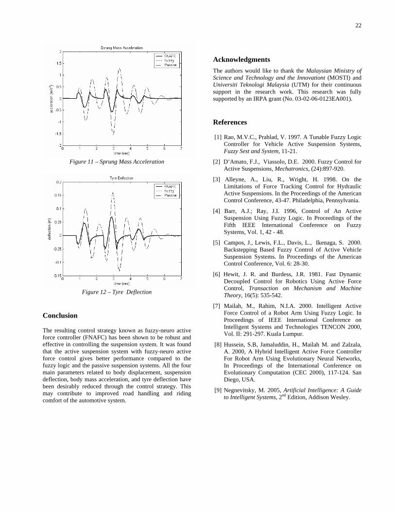
3.11 Sprung Mass Acceleration 22
3.12 Tyre Deflection 22
4.1 Quarter Car Vehicle Suspension 28
xiv
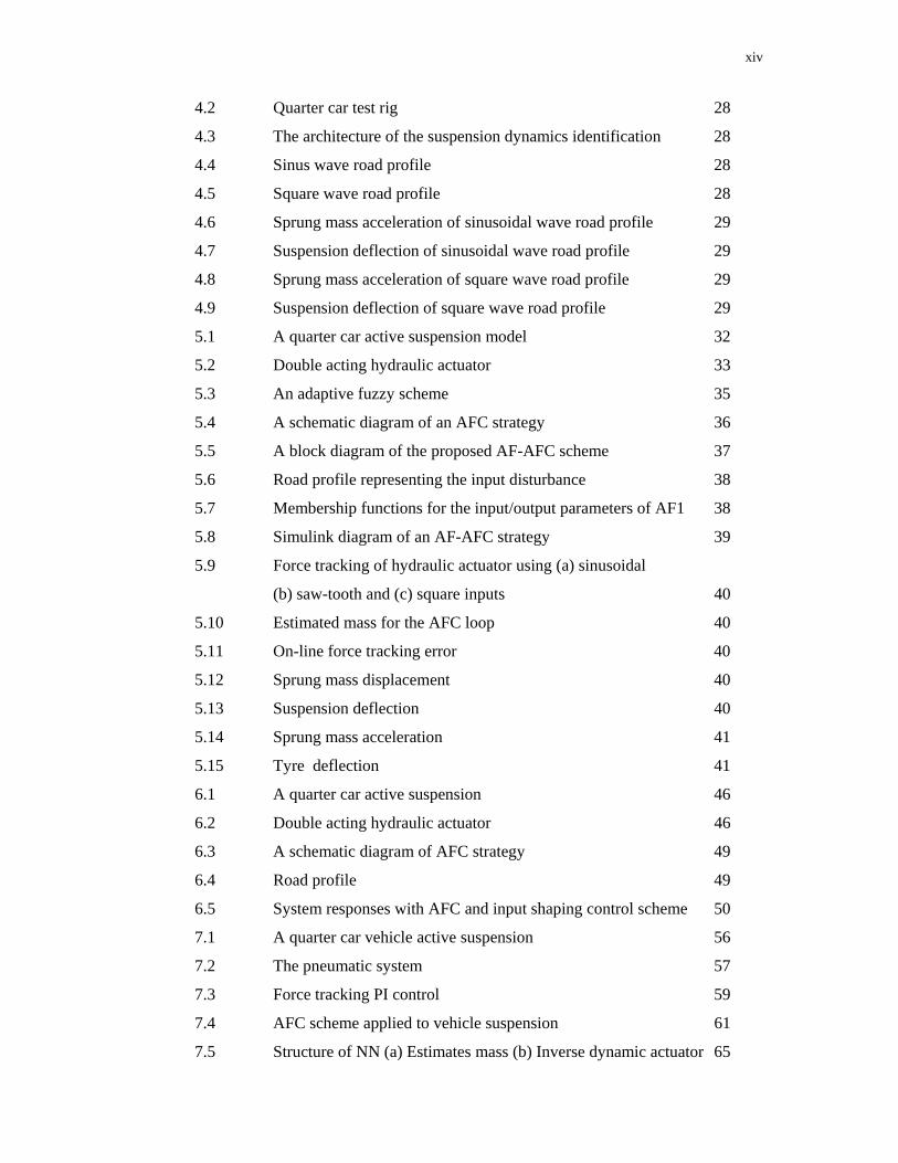
4.2 Quarter car test rig 28
4.3 The architecture of the suspension dynamics identification 28
4.4 Sinus wave road profile 28
4.5 Square wave road profile 28
4.6 Sprung mass acceleration of sinusoidal wave road profile 29
4.7 Suspension deflection of sinusoidal wave road profile 29
4.8 Sprung mass acceleration of square wave road profile 29
4.9 Suspension deflection of square wave road profile 29
5.1 A quarter car active suspension model 32
5.2 Double acting hydraulic actuator 33
5.3 An adaptive fuzzy scheme 35
5.4 A schematic diagram of an AFC strategy 36
5.5 A block diagram of the proposed AF-AFC scheme 37
5.6 Road profile representing the input disturbance 38
5.7 Membership functions for the input/output parameters of AF1 38
5.8 Simulink diagram of an AF-AFC strategy 39
5.9 Force tracking of hydraulic actuator using (a) sinusoidal
(b) saw-tooth and (c) square inputs 40
5.10 Estimated mass for the AFC loop 40
5.11 On-line force tracking error 40
5.12 Sprung mass displacement 40
5.13 Suspension deflection 40
5.14 Sprung mass acceleration 41
5.15 Tyre deflection 41
6.1 A quarter car active suspension 46
6.2 Double acting hydraulic actuator 46
6.3 A schematic diagram of AFC strategy 49
6.4 Road profile 49
6.5 System responses with AFC and input shaping control scheme 50
7.1 A quarter car vehicle active suspension 56
7.2 The pneumatic system 57
7.3 Force tracking PI control 59
7.4 AFC scheme applied to vehicle suspension 61
7.5 Structure of NN (a) Estimates mass (b) Inverse dynamic actuator 65
xv
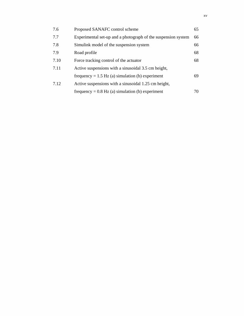
7.6 Proposed SANAFC control scheme 65
7.7 Experimental set-up and a photograph of the suspension system 66
7.8 Simulink model of the suspension system 66
7.9 Road profile 68
7.10 Force tracking control of the actuator 68
7.11 Active suspensions with a sinusoidal 3.5 cm height,
frequency = 1.5 Hz (a) simulation (b) experiment 69
7.12 Active suspensions with a sinusoidal 1.25 cm height,
frequency = 0.8 Hz (a) simulation (b) experiment 70
xvi
LIST OF SYMBOLS / ABBREVIATIONS
SYMBOL
SUBJECT
A
a
bs
Cd
Ctm
dk
ek
F*
Fa
fa
ks
kt
M
ms
mu
Ok
p
QL
Vt
w
wk
wk+1
xi
ya
Actuator ram area
Measured acceleration of the body
Damping coefficient
Discharge coefficient
Coefficient of total leakage due to pressure
Teach data or desired output
Partial network error
Compensated or estimated force
Measured force of the actuator
Actuator force
Spring stiffness
Tyre stiffness
Estimated mass of the body
Sprung mass
Unsprung mass
Output of neural networks
Number of available patterns
Total flow
Total actuator volume
Spool valve area gradient
Current step weight
Next step weight
Input to the fuzzy networks
Actual output
xvii
yd
zr
zs
zu
sz&
uz&
zs – zu
zu – zr
α
β
ξ
ω
Desired output
Displacement of road
Displacement of the car body
Displacement of wheel (unsprung)
Velocity of car body
Velocity of wheel
Suspension deflection
Tyre deflection
Set constant
Effective bulk modulus
Damping ratio of the system
Natural frequency
A/D Analogue-to-Digital
AFAFC Adaptive Fuzzy Active Force Control
AFC Active Force Control
AFCIS Active Force Control with Input Shaping
AFL Adaptive Fuzzy Logic
BP Backpropagation
D/A Digital-to-Analogue
DAS Data Acquisition System
FL Fuzzy Logic
FLAFC Fuzzy Logic Active Force Control
FNAFC Fuzzy Neuro Active Force Control
I/O Input/Output
IS Input Shaping
LM Levenberg-Marquardt
LVDT Linear Variable Differential Transformer
NN Neural Network
PC Personal Computer
PI Proportional-Integral
PID Proportional-Integral-Derivative
PIDAFC Proportional-Integral-Derivative and Active Force Control
xviii
PLC Programmable Logic Controller
PSO Particle Swarm Optimisation
RTW Real-Time Workshop
SANAFC Skyhook Adaptive Neuro Active Force Control
CHAPTER 1
INTRODUCTION
1.1 General Introduction
Suspension system is indeed an integral component of a vehicle. The main
requirements of a vehicle suspension are that it should be able to minimize the
vertical displacement and the acceleration of the body in order to increase the
passenger comfort, minimize the dynamic tyre load to provide maximum road
handling and react to the changes of mass payload. It is generally thought that in
order to achieve a good ride comfort, the suspension should be soft enough, whereas
for good road handling capability, it requires stiff suspension. Because of these
conflicting demands, suspension design has had to be something of a compromise,
which is largely determined by the type of vehicle usage. In the conventional or
passive suspension system, the mass-spring-damper parameters are generally fixed,
and they are chosen based on the design requirements of the vehicles. The
suspension has the ability to store energy in the spring and dissipate it through the
damper. When a spring supports a load, it will compress until the force produced by
the compression is equal to that of the load on it. If some other force then disturbs the
load, then the load will oscillate up and down or fluctuate around its original position
for a period of time. Passive suspension system utilizing mechanical springs and
dampers is known to have the limitations of vibration isolation and lack of altitude
control of the vehicle body. To overcome these problems, many researchers have
studied various active and semi-active suspensions both theoretically and
experimentally.
2
In semi active suspension systems, it still employs springs as the main form
of support, however the dampers can usually be controlled. A semi active suspension
has the ability to change the damping characteristics of the shock absorbers without
any use of actuators. Recently, electrorheological (ER) and magnetorheological
(MR) fluids are used in order to control the dampers. Active suspension differs from
the conventional passive suspension in their ability to inject energy into the system.
In an active suspension system, an actuator is connected in parallel with a spring and
a shock absorber in between the sprung and unsprung masses. The actuator is used to
generate the desired force in any direction, regardless of the relative velocity across it
to achieve the desired performance. The ability to control the energy from external
source according to the environment provides the flexibility in control and better
performance of suspension system. For this reason, the active suspension is widely
investigated and studied.
1.2 Outline of Research
The active force control (AFC) strategy applied to dynamical system has been
first introduced by Hewit (Hewit and Burdess, 1981). AFC has been shown to be
very robust and practical in compensating disturbances and changes in the
parameters when applied to a dynamic system. The method involves the
measurements of two physical quantities (acceleration of the main physical system
and the applied force) and the appropriate estimation of the mass matrix of the
system. This involves the use of precision sensors and appropriate approximation
technique (via intelligent method). Excellent results obtained from the previous
simulation studies imply the effectiveness of both the intelligent mechanisms. In the
proposed research, intelligent AFC technique featuring the extreme robustness
characteristic is exploited to the control of an automotive suspension system by
introducing an active element in the form of disturbance rejector mechanism which
will considerably improve system performance particularly related to human riding
comfort aspect in the event the system encounters a number of adverse conditions
due to vibration, uneven road surfaces, ‘bumps’ and ‘holes’. The research
3
emphasizes the full development of the system to be investigated both theoretically
as well as experimentally. The use of intelligent AFC applied to the system might
include iterative learning (IL) algorithm, neural network (NN), fuzzy logic (FL) or
their combination (hybrid).
1.3 Objective of Research
The specific objectives of research are:
• To develop a very robust active suspension system using intelligent active
force control strategy
• To simulate and study the performance of the proposed system
• To design and develop a prototype of the experimental automotive
suspension system.
1.4 Scope of Research
The scope of research shall encompass the followings:
• Literature review on vehicle suspension modelling, active control and
intelligent systems.
• Only a quarter car model is considered and a vertical displacement of the
sprung mass (body) is assumed.
• Theoretical design and simulation of a number of advanced robust control
schemes based on Active Force Control (AFC) with intelligent elements,
namely fuzzy logic (FL), neural network (NN) or combination (hybrid). The
main software design tool is MATLAB/Simulink.
4
• Design and development of an experimental suspension system including
mechatronics design of the suspension, PC-based interfacing, sensors and
actuators interfacing and a robot controller programming using C language. A
hardware-in-the-loop system based on MATLAB/Simulink and Real-Time
Workshop (RTW) shall be rigorously experimented.
1.5 Research Methodology
The project will be divided into five main stages. These are modelling and
simulation, incorporation of intelligent controller, design and development of the
prototype, experimentation and performance analysis. Initially these areas will be
investigated separately by groups of researchers under the supervision of a project
leader. Ideas and findings by all the groups will be presented to other group members
for transfer of knowledge and experience. Mechatronic approach involving the
synergy of mechanical, electrical/electronics and computer (software) control would
be the main feature of the research methodology. The more detailed description of
the research methodology is as follows:
i. Modelling and simulation
The modelling and simulation phase involves rigorous manipulation of mathematical
equations representing the system’s dynamics and kinematics. Computer
programming and software utilisation at this juncture are of prime importance and
indispensable. A suitable and practical quarter-car or half-car model based on real
physical system will be identified and scrutinized for the above-mentioned purpose.
Realistic and valid assumptions based on the proposed system will be made in the
process. A number of intelligent methods such as NN, FL, EC and IL or their
combination (hybrid) will be studied and later implemented with the parent AFC
strategy to control the system. Their algorithms and techniques will be thoroughly
investigated and studied. Comprehensive simulation works will include the
evaluation of the system’s performance and robustness against various forms of
5
disturbances, vibration and other different operating and loading conditions. Changes
in the parameters such as those related to the physical values of the mechanical
spring-damper system, simulation and learning algorithms will also be also taken
into account. Expected results to be analysed are the frequency and time responses,
body acceleration, and the effects of the introduced disturbances and other given
conditions. A comparative study between a number of control strategies will also be
considered to provide a useful platform in determining the ‘optimum’ and best
control method. The modelling and simulation work would serve as a basis for
designing and developing the prototype (experimental rig) in later stages.
ii. Incorporation of intelligent controller
A suitable intelligent controller will be identified based on the outcome of the
simulation study. The controller is chosen in the form of control algorithm such that
its practical implementation in real time is feasible and readily applied. Relevant
parameters of the controller will be refined and related computer program will be
written for this purpose. Development of a possible hardware for the controller will
be fully investigated and looked into. This will largely involve aspects of computer
programming, interfacing, electrical/electronics and sensory feedbacks. Digital
control based on the PC system is employed and the application of microcontroller is
a possibility and will be relevantly explored.
iii. Design and development of the prototype
Mechatronics approach is emphasized here encompassing the aspects of
mechanical, electrical/electronics and computer control. A complete integration of
the mentioned disciplines is very essential.
Mechanical: Mechanical design initially involves the conceptual design of the
physical suspension system and related mechanisms. A number of factors and
suitable design criteria should be carefully considered in the design process. A
finalized design is subsequently chosen with the detailed production drawings
ensued for fabrication purposes. Some of the mechanical aspects of the system
such as the computation of the parameters for the hydraulic servo mechanism, the
6
length of actuator’s stroke, dimensions of the system structure or parts can be
obtained and/or manipulated from the simulation study.
Electrical/electronics: Electrical and electronics will include proper selection of
sensor, motor, driver, controller or amplifier. Instrumentation is also involved and
a number of selected electronic circuitries would be exploited and utilised in the
research. A good knowledge and skill in electronics assembly is highly desirable
at this stage. Again, the outcome from the simulation works help in determining
for example the size (power, force, torque etc.) of the electric actuator to be used.
Computer control: The next stage will involve rigorous computer interfacing and
control involving data acquisition process through the use of analogue-to-digital-
digital-to-analogue (ADDA) card and a PC for software control. Computer
programming at this stage is of paramount importance since it serves as the link
between the mechanical and electrical/electronics components. Again, digital
control is applied here to also include item (ii).
iv. Experimentation
When the mechatronic system prototype is ready, experimental procedures will be
drafted and testing will be done to validate the effectiveness and the robustness of
the control strategy. Possible modification of the system can be carried out at this
stage to enhance the system’s performance. Experimentation will be rigorously
carried out to test the effectiveness of the proposed system. The tests will take into
account various operating and loading conditions.
v. Performance evaluation and analysis
Finally, the system’s performance will be critically evaluated and analysed. This
includes the results obtained from both the simulated and prototype developmental
activities. The research outcomes should provide insights and information which
would be useful for future development, improvement and expansion of the system.
In addition to that, suggestion for further research works will also be outlined.

7
1.6 Organization of Report
The report is organized into eight chapters. Chapter 1 deals with the
description of research background, objectives, scope and methodology. Chapters 2
to 7 are actually technical papers that are either published in or submitted to
conference proceedings and journals at both national and international levels.
Chapter 2: Control Design of A Quarter Car Suspension System using Fuzzy
Logic Active Force Control.
Chapter 3: Fuzzy Logic Artificial Neural Network Active Force Control for
an Active Suspension of a Quarter Car.
Chapter 4: Particle Swarm Optimization Neural Network Based Modelling of
Vehicle Suspension System.
Chapter 5: Simulation of A Suspension System With Adaptive Fuzzy Active
Force Control.
Chapter 6: Hybrid Control Scheme Incorporating AFC and Input Shaping
Technique For A Suspension System.
Chapter 7: Vehicle Active Suspension System Using Skyhook Adaptive
Neuro Active Force Control.
Finally, Chapter 8 concludes the research project. The directions and
recommendations for future research works are also outlined in this chapter. Some of
the additional materials pertaining to relevant results of the study, photographs of rig,
publications and achievements related to the research are enclosed in the appendices.
9
Controller Design for an Active Suspension of a Quarter Car Model Using Fuzzy Logic Active Force Control
Gigih Priyandoko and Musa Mailah
Intelligent Active Force Control Research Group Department of Applied Mechanics, Faculty of Mechanical Engineering
Universiti Teknologi Malaysia 81310 Skudai, Johor
MALAYSIA
[email protected] and [email protected]
ABSTRACT This paper discusses the design of a novel control technique for an active vehicle suspension system
using fuzzy logic (FL) controller with an active force control (AFC) element. The control strategy is implemented to control a nonlinear actuator attached between the sprung mass and the unsprung mass of the quarter car model that provides the energy into the system based on the control signal through feedback information from the sensors placed at strageic location in the system. The performance of the proposed control scheme is then evaluated and compared with other methods to examine the effectiveness of the scheme in suppressing the vibration and other disturbances presence in the passenger car suspension system. Results show that an active suspension system with fuzzy logic active force control (FLAFC) produced a much improved desirable performance compared to the pure FL controller and the passive suspension systems.
1. INTRODUCTION
In designing suspension system, there should be a compromise between the passenger comfort and good handling of the vehicle. The main requirements of a vehicle suspension are that it should be able to minimize the vertical displacement and the acceleration of the body in order to increase the passenger comfort, minimize the dynamic tyre load to provide maximum road handling and react to the changes of mass payload. It is generally thought that in order to achieve a good ride comfort, the suspension should be soft enough, whereas for good road handling capability, it requires stiff suspension. Because of these conflicting demands, suspension design has had to be something of a compromise, which is largely determined by the type of vehicle usage. In the conventional or passive suspension system, the mass-spring-damper parameters are generally fixed, and they are chosen based on the design requirements of the vehicles. The suspension has the ability to store energy in the spring and dissipate it through the damper. When a spring supports a load, it will compress until the force produced by the compression is equal to that of the load on it. If some other force then disturbs the load, then the load will oscillate up and down or fluctuate around its original position for a period of time. Passive suspension system utilizing mechanical springs and dampers is known to have the limitations of vibration isolation and lack of altitude control of the vehicle body. To overcome these problems, many researchers have studied various active and semi-active suspensions both theoretically and experimentally.
In semi active suspension systems, it still employs springs as the main form of support, however the dampers can usually be controlled. A semi active suspension has the ability to change the damping characteristics of the shock absorbers without any use of actuators. Recently, electrorheological (ER) and magnetorheological (MR) fluids are used in order to control the dampers [1]. Active suspension differs from the conventional passive suspension in their ability to inject energy into the system. In an active suspension system, an actuator is connected in parallel with a spring and a shock absorber in between the sprung and unsprung masses. The actuator is used to generate the desired force in any direction, regardless

10
of the relative velocity across it to achieve the desired performance. The ability to control the energy from external source according to the environment provides the flexibility in control and better performance of suspension system. For this reason, the active suspension is widely investigated and studied.
A number of techniques and design methodologies have been proposed. Linear Quadratic Regulator control, Linear Quadratic Gaussian control, adaptive control, nonlinear control, among other techniques, have been used to reduce the parameters of close loop suspension system [2,3]. However, an accurate system model must be available before the controller can be developed and applied.
Fuzzy logic (FL) control methods have been used extensively in recent years in a number of applications such as automatic transmission, Sendai subway operation, cold rolling mills, self-parking model car, image stabilizer for video camera and fully automated washing machine [4]. Fuzzy logic controller has also been successfully implemented in an active suspension systems [5-7]. Unlike conventional controllers, a fuzzy logic control law does not require a mathematical modelling and it can be easily realized on a single integrated circuit (IC) chip .
The objective of this research is to design a controller of active suspension system to minimize vertical body displacement, suspension deflection, tyre deflection and body acceleration using fuzzy logic AFC strategy, thereby improving the system’s overall performance. The paper is organized as follows. The dynamics of a quarter car model is introduced in section 2 while that of a double acting hydraulic strut in section 3. AFC strategy and fuzzy logic controller are described in section 4 and 5 respectively. The results of the simulation are discussed in section 6. Finally, this paper is concluded in section 7.
2. DYNAMICS OF AN ACTIVE SUSPENSION SYSTEM
The model of the quarter car active suspension system used in the study is shown in Figure 1. It is presented by a two-degrees-of-freedom model.
zs
zu
zr
fa bs ks
kt
mssprung
muunsprung
road terrain
Figure 1. A quarter car active suspension. The equations of motion for this system are given as follows [8]:
arutussussuu
aussussss
f)zz(k)zz(b)zz(kzmf)zz(b)zz(kzm
−−−−+−=+−−−−=
&&&&
&&&& (1)
where ms = sprung mass mu = unsprung mass bs = damping coefficient

11
ks = spring stiffness kt = tyre stiffness fa = actuator force zs = displacement of the car body zu = displacement of wheel (unsprung) zr = displacement of road zs – zu = suspension deflection zu – zr = tyre deflection
sz& = velocity of car body
uz& = velocity of wheel
It is assumed that the suspension spring and tyre stiffnesses are linear in their operation range, the tyre does not leave the ground and that the displacement of body and wheel are measured from the static equilibrium point. 3. DYNAMICS OF A DOUBLE ACTING HYDRAULIC STRUT
Figure 2 depicts a schematic diagram of a translational double acting hydraulic actuator driven by a three-land four-way spool valve. An actuator is assumed to be placed between the sprung and unsprung masses and can exert a force fa in between ms and mu.
Figure 2. A double acting hydraulic strut
The hydraulic actuator consists of a spool valve (servo valve) and a hydraulic cylinder as shown in the
figure. Ps and Pr are the supply and return pressure going into and out of the spool valve respectively. xv is the spool valve position. Pu and Pl are the oil pressure in the upper and lower cylinder chambers respectively. xw-xc is the hydraulic piston displacement. The differential equation governing the dynamics of the actuator is given as follows [8]:
)(4 usLtmLL
t zzAPCQPV&&& −−−=
β (2)
where Vt = total actuator volume β = effective bulk modulus A = actuator ram area Ctm = coefficient of total leakage due to pressure
QL = total flow given by
12
ρLvs
vdLPxPwxCQ )sgn(−
= (3)
where Cd = discharge coefficient w = spool valve area gradient
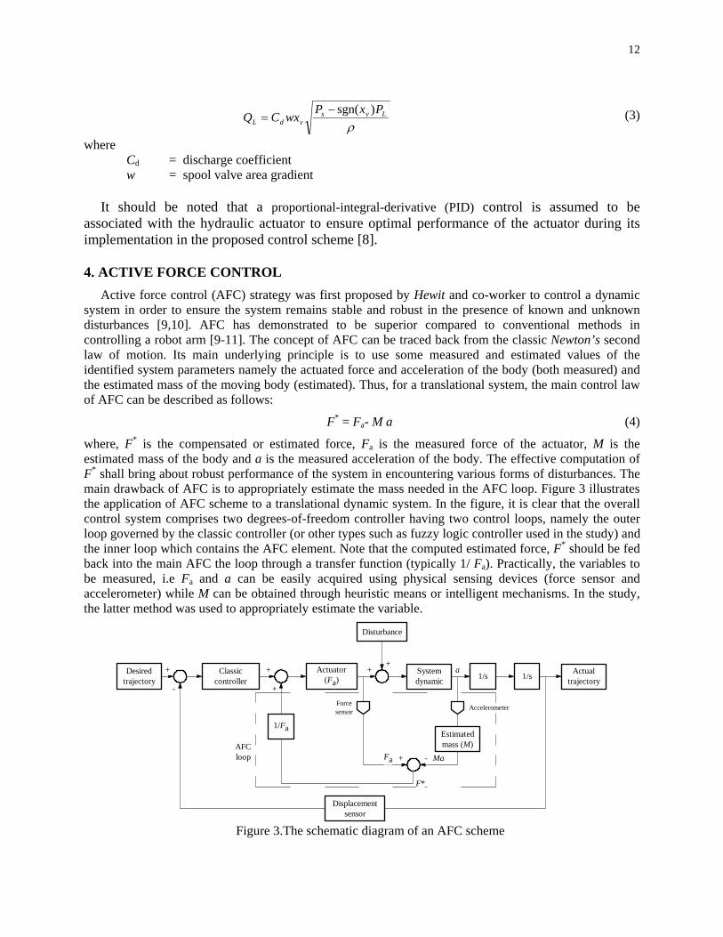
It should be noted that a proportional-integral-derivative (PID) control is assumed to be associated with the hydraulic actuator to ensure optimal performance of the actuator during its implementation in the proposed control scheme [8]. 4. ACTIVE FORCE CONTROL Active force control (AFC) strategy was first proposed by Hewit and co-worker to control a dynamic system in order to ensure the system remains stable and robust in the presence of known and unknown disturbances [9,10]. AFC has demonstrated to be superior compared to conventional methods in controlling a robot arm [9-11]. The concept of AFC can be traced back from the classic Newton’s second law of motion. Its main underlying principle is to use some measured and estimated values of the identified system parameters namely the actuated force and acceleration of the body (both measured) and the estimated mass of the moving body (estimated). Thus, for a translational system, the main control law of AFC can be described as follows:
F* = Fa- M a (4)
where, F* is the compensated or estimated force, Fa is the measured force of the actuator, M is the estimated mass of the body and a is the measured acceleration of the body. The effective computation of F* shall bring about robust performance of the system in encountering various forms of disturbances. The main drawback of AFC is to appropriately estimate the mass needed in the AFC loop. Figure 3 illustrates the application of AFC scheme to a translational dynamic system. In the figure, it is clear that the overall control system comprises two degrees-of-freedom controller having two control loops, namely the outer loop governed by the classic controller (or other types such as fuzzy logic controller used in the study) and the inner loop which contains the AFC element. Note that the computed estimated force, F* should be fed back into the main AFC the loop through a transfer function (typically 1/ Fa). Practically, the variables to be measured, i.e Fa and a can be easily acquired using physical sensing devices (force sensor and accelerometer) while M can be obtained through heuristic means or intelligent mechanisms. In the study, the latter method was used to appropriately estimate the variable.
Desired trajectory
Classiccontroller
1/Fa
Actuator (Fa)
Disturbance
System dynamic 1/s 1/s
Estimated mass (M)
Displacement sensor
Actual trajectory
AccelerometerForcesensor
+
-
+
+
++
+ -AFC loop
a
F*
Fa Ma
Figure 3.The schematic diagram of an AFC scheme
13
5. FUZZY LOGIC CONTROLLER
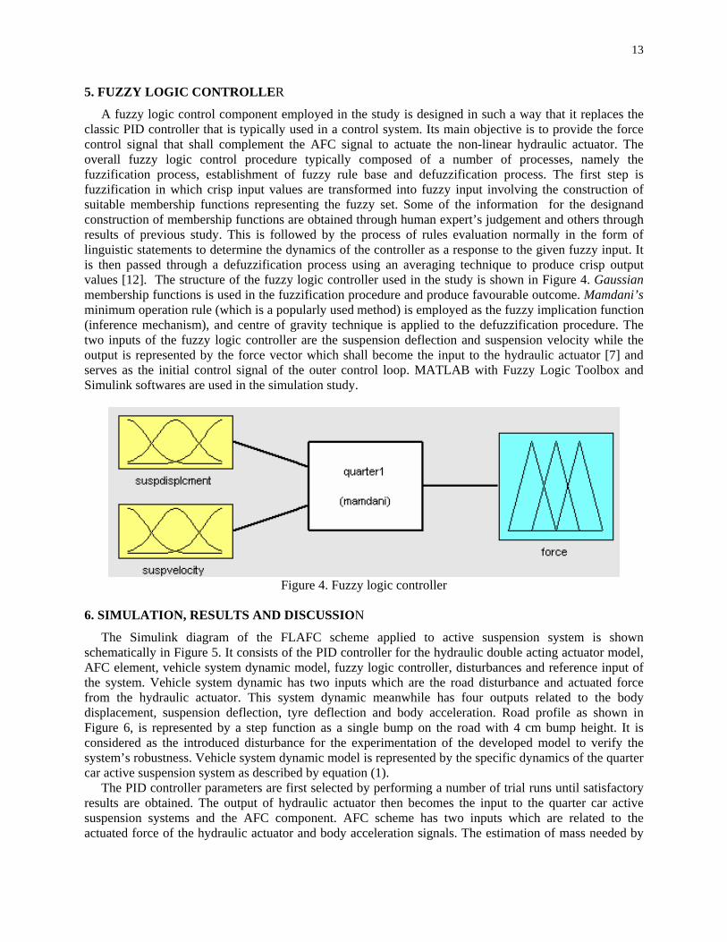
A fuzzy logic control component employed in the study is designed in such a way that it replaces the classic PID controller that is typically used in a control system. Its main objective is to provide the force control signal that shall complement the AFC signal to actuate the non-linear hydraulic actuator. The overall fuzzy logic control procedure typically composed of a number of processes, namely the fuzzification process, establishment of fuzzy rule base and defuzzification process. The first step is fuzzification in which crisp input values are transformed into fuzzy input involving the construction of suitable membership functions representing the fuzzy set. Some of the information for the designand construction of membership functions are obtained through human expert’s judgement and others through results of previous study. This is followed by the process of rules evaluation normally in the form of linguistic statements to determine the dynamics of the controller as a response to the given fuzzy input. It is then passed through a defuzzification process using an averaging technique to produce crisp output values [12]. The structure of the fuzzy logic controller used in the study is shown in Figure 4. Gaussian membership functions is used in the fuzzification procedure and produce favourable outcome. Mamdani’s minimum operation rule (which is a popularly used method) is employed as the fuzzy implication function (inference mechanism), and centre of gravity technique is applied to the defuzzification procedure. The two inputs of the fuzzy logic controller are the suspension deflection and suspension velocity while the output is represented by the force vector which shall become the input to the hydraulic actuator [7] and serves as the initial control signal of the outer control loop. MATLAB with Fuzzy Logic Toolbox and Simulink softwares are used in the simulation study.
Figure 4. Fuzzy logic controller
6. SIMULATION, RESULTS AND DISCUSSION
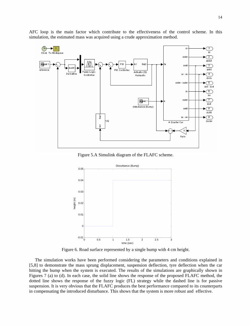
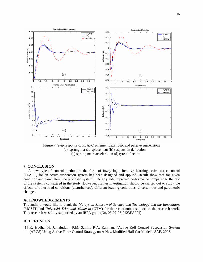
The Simulink diagram of the FLAFC scheme applied to active suspension system is shown schematically in Figure 5. It consists of the PID controller for the hydraulic double acting actuator model, AFC element, vehicle system dynamic model, fuzzy logic controller, disturbances and reference input of the system. Vehicle system dynamic has two inputs which are the road disturbance and actuated force from the hydraulic actuator. This system dynamic meanwhile has four outputs related to the body displacement, suspension deflection, tyre deflection and body acceleration. Road profile as shown in Figure 6, is represented by a step function as a single bump on the road with 4 cm bump height. It is considered as the introduced disturbance for the experimentation of the developed model to verify the system’s robustness. Vehicle system dynamic model is represented by the specific dynamics of the quarter car active suspension system as described by equation (1).
The PID controller parameters are first selected by performing a number of trial runs until satisfactory results are obtained. The output of hydraulic actuator then becomes the input to the quarter car active suspension systems and the AFC component. AFC scheme has two inputs which are related to the actuated force of the hydraulic actuator and body acceleration signals. The estimation of mass needed by
14
AFC loop is the main factor which contribute to the effectiveness of the control scheme. In this simulation, the estimated mass was acquired using a crude approximation method.
Figure 5.A Simulink diagram of the FLAFC scheme.
0 0.5 1 1.5 2 2.5 3-0.01
0
0.01
0.02
0.03
0.04
0.05Disturbance (Bump)
time (sec)
heig
ht (m
)
Figure 6. Road surface represented by a single bump with 4 cm height.
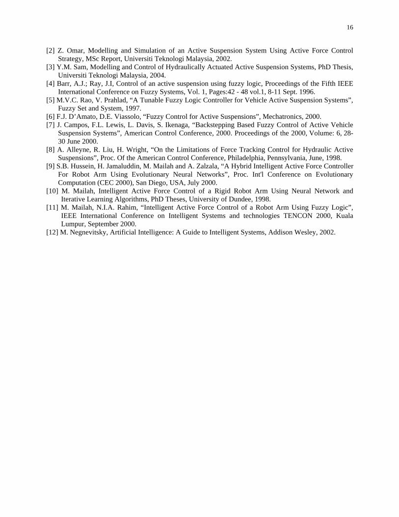
The simulation works have been performed considering the parameters and conditions explained in
[5,8] to demonstrate the mass sprung displacement, suspension deflection, tyre deflection when the car hitting the bump when the system is executed. The results of the simulations are graphically shown in Figures 7 (a) to (d). In each case, the solid line shows the response of the proposed FLAFC method, the dotted line shows the response of the fuzzy logic (FL) strategy while the dashed line is for passive suspension. It is very obvious that the FLAFC produces the best performance compared to its counterparts in compensating the introduced disturbance. This shows that the system is more robust and effective.
15
Figure 7. Step response of FLAFC scheme, fuzzy logic and passive suspensions
(a) sprung mass displacement (b) suspension deflection (c) sprung mass acceleration (d) tyre deflection
7. CONCLUSION
A new type of control method in the form of fuzzy logic iterative learning active force control (FLAFC) for an active suspension system has been designed and applied. Result show that for given condition and parameters, the proposed system FLAFC yields improved performance compared to the rest of the systems considered in the study. However, further investigation should be carried out to study the effects of other road conditions (disturbances), different loading conditions, uncertainties and parametric changes.
ACKNOWLEDGEMENTS The authors would like to thank the Malaysian Ministry of Science and Technology and the Innovationt (MOSTI) and Universiti Teknologi Malaysia (UTM) for their continuous support in the research work. This research was fully supported by an IRPA grant (No. 03-02-06-0123EA001).
REFERENCES [1] K. Hudha, H. Jamaluddin, P.M. Samin, R.A. Rahman, “Active Roll Control Suspension System
(ARCS) Using Active Force Control Strategy on A New Modified Half Car Model”, SAE, 2003.
16
[2] Z. Omar, Modelling and Simulation of an Active Suspension System Using Active Force Control Strategy, MSc Report, Universiti Teknologi Malaysia, 2002.
[3] Y.M. Sam, Modelling and Control of Hydraulically Actuated Active Suspension Systems, PhD Thesis, Universiti Teknologi Malaysia, 2004.
[4] Barr, A.J.; Ray, J.I, Control of an active suspension using fuzzy logic, Proceedings of the Fifth IEEE International Conference on Fuzzy Systems, Vol. 1, Pages:42 - 48 vol.1, 8-11 Sept. 1996.
[5] M.V.C. Rao, V. Prahlad, “A Tunable Fuzzy Logic Controller for Vehicle Active Suspension Systems”, Fuzzy Set and System, 1997.
[6] F.J. D’Amato, D.E. Viassolo, “Fuzzy Control for Active Suspensions”, Mechatronics, 2000. [7] J. Campos, F.L. Lewis, L. Davis, S. Ikenaga, “Backstepping Based Fuzzy Control of Active Vehicle
Suspension Systems”, American Control Conference, 2000. Proceedings of the 2000, Volume: 6, 28-30 June 2000.
[8] A. Alleyne, R. Liu, H. Wright, “On the Limitations of Force Tracking Control for Hydraulic Active Suspensions”, Proc. Of the American Control Conference, Philadelphia, Pennsylvania, June, 1998.
[9] S.B. Hussein, H. Jamaluddin, M. Mailah and A. Zalzala, “A Hybrid Intelligent Active Force Controller For Robot Arm Using Evolutionary Neural Networks”, Proc. Int'l Conference on Evolutionary Computation (CEC 2000), San Diego, USA, July 2000.
[10] M. Mailah, Intelligent Active Force Control of a Rigid Robot Arm Using Neural Network and Iterative Learning Algorithms, PhD Theses, University of Dundee, 1998.
[11] M. Mailah, N.I.A. Rahim, “Intelligent Active Force Control of a Robot Arm Using Fuzzy Logic”, IEEE International Conference on Intelligent Systems and technologies TENCON 2000, Kuala Lumpur, September 2000.
[12] M. Negnevitsky, Artificial Intelligence: A Guide to Intelligent Systems, Addison Wesley, 2002.
CHAPTER 2
CONTROL DESIGN OF A QUARTER CAR SUSPENSION SYSTEM USING FUZZY LOGIC ACTIVE FORCE CONTROL
Gigih Priyandoko & Musa Mailah
Presented at International Conference on Mechatronics 2005 (ICOM05), Kuala
Lumpur, May 2005
18
Fuzzy-Neuro Active Force Control of a Quarter Car Suspension System
Gigih Priyandoko, Musa Mailah
Intelligent Active Force Control Research Group,
Department of Applied Mechanics, Faculty of Mechanical Engineering, Universiti Teknologi Malaysia, 81310 Skudai, Johor Tel:+6075535942, E-mail: [email protected], [email protected]
Abstract This paper presents the design of a control technique applied to an active suspension system of a quarter car model using fuzzy logic controller with artificial neural network embedded in the active force control component. The overall control system is decomposed into two loops. In the main loop, the desired force signal is calculated using an active force control strategy with a neural network element being employed to estimate the mass needed to feed the forward control loop. A fuzzy logic controller is implemented in the outer loop to design a force controller such that the desired force signal is achieved in a robust manner. The resulting control strategy known as fuzzy-neuro active force controller (FNAFC), is then used to control a nonlinear actuator attached between the sprung mass and the unsprung mass of the quarter car model. The performances of the proposed control method were then evaluated and later compared to examine the effectiveness in suppressing the vibration effect of the suspension system. It was found that the active suspension system with fuzzy-neuro active force control gives better performance compared to the fuzzy logic and the passive suspension system. Keywords Active suspension, quarter car, fuzzy logic control, artificial neural network, active force control.
Introduction
For many years, automobile suspension primarily consists of a coil or leaf spring in parallel with viscous damper. The control of automobile suspensions is currently of great interest in both the academic and industrial fields. Suspension design requires a compromise between the passenger comfort and good handling vehicle. To provide a good ride comfort, the suspension should be soft enough, but whereas good road holding requires stiff suspension. A good vehicle suspension should be able to minimize the vertical displacement and the acceleration of the body, however, in order to increase the passenger comfort, the sprung mass displacement need to be minimized. In the conventional passive suspension system, the mass-spring-damper parameters are generally fixed, and they are chosen based on the design requirements of the vehicles. The suspension has the ability to store energy in the spring and to dissipate it through the damper. When a spring supports a load, it will compress until the force produced by the compression is equal to the load force. If some other forces then disturb the
load, then the load will oscillate up and down around its original position for some time. Passive suspension utilizing mechanical springs and dampers is known to have the limitations of vibration isolation and lack of attitude control of the vehicle body. To solve these problems, many researchers have studied various active and semi-active suspensions both theoretically and experimentally. In semi active suspension systems, it still uses springs as the main form of support, however the dampers can be controlled. A semi active suspension has the ability to change the damping characteristics of the shock absorbers without using any actuators. Active suspension differs from the conventional passive suspension in its ability to inject energy into the system. In an active suspension system, an actuator is attached in parallel with both a spring and a shock absorber. To achieve the desired performance, actuator should generate the desired force in any direction, regardless of the relative velocity across it. The ability to control the energy from external source according to the environment provides better performance of suspension system. For this reason, the active suspension has been widely investigated [1-5]. The objective of this study is to design a controller of active suspension system that can reduce the vertical body displacement, suspension deflection, tyre deflection and body acceleration using fuzzy logic neural network active force control (FNAFC) strategy.
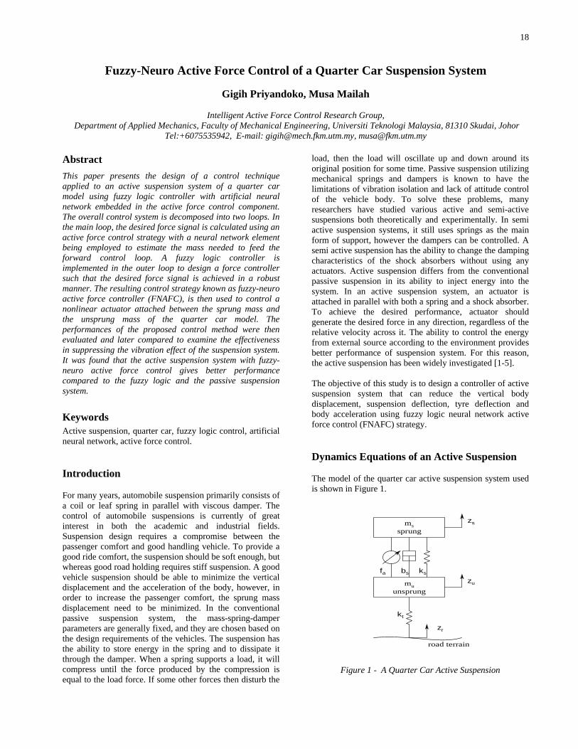
Dynamics Equations of an Active Suspension
The model of the quarter car active suspension system used is shown in Figure 1.
zs
zu
zr
fa bs ks
kt
mssprung
muunsprung
road terrain
Figure 1 - A Quarter Car Active Suspension
19
The quarter car model is presented by a two degrees-of-freedom model. The equations of motion for this system are given as [3]:
arutussussuu
aussussss
fzzkzzbzzkzmfzzbzzkzm
−−−−+−=+−−−−=
)()()()()(
&&&&
&&&& (1)
where
ms is the sprung mass (body) mu is the unsprung mass (wheel) bs is the damping coefficient ks is the spring stiffness kt is the tyre stiffness fa is the actuator force zs is the displacement of the car body zu is the displacement of wheel zr is the displacement of road zs–zu is the suspension deflection zu – zr is the tyre deflection
sz& is the velocity of the car body
uz& is the velocity of wheel By assuming that the suspension spring and tyre stiffnesses are linear in their operating ranges, the tyre does not leave the ground. The displacements of both the body and wheel can be measured from the static equilibrium point.
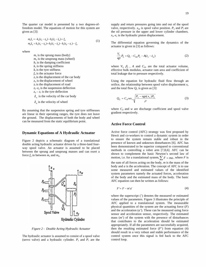
Dynamic Equations of A Hydraulic Actuator
Figure 2 depicts a schematic diagram of a translational double acting hydraulic actuator driven by a three-land four-way spool valve. An actuator is assumed to be placed between the sprung and unsprung masses and can exert a force fa in between ms and mu.
Figure 2 - Double Acting Hydraulic Actuator The hydraulic actuator is assumed to consist of a spool valve (servo valve) and a hydraulic cylinder. Ps and Pr are the
supply and return pressures going into and out of the spool valve, respectively. xsp is spool valve position. Pu and Pl are the oil pressure in the upper and lower cylinder chambers. xw-xc is the hydraulic piston displacement. The differential equation governing the dynamics of the actuator is given in [3] as follows:
)(4 usLtmLL
t zzAPCQPV
&&& −−−=β
(2)
where Vt, βe , A and Ctm are the total actuator volume, effective bulk modulus, actuator ram area and coefficient of total leakage due to pressure respectively. Using the equation for hydraulic fluid flow through an orifice, the relationship between spool valve displacement xv and the total flow QL is given as [3]:
ρLvs
vdLPxP
wxCQ)sgn(−
= (3)
where Cd and w are discharge coefficient and spool valve gradient respectively.
Active Force Control
Active force control (AFC) strategy was first proposed by Hewit and co-workers to control a dynamic system in order to ensure the system remain stable and robust in the presence of known and unknown disturbances [6]. AFC has been demonstrated to be superior compared to conventional methods in controlling a robot arm [7,8,6]. AFC can be shown to complement the basic Newton’s second law of motion, i.e. for a translational system,∑ = maF , where F is the sum of all forces acting on the body, m is the mass of the body and a is the acceleration. The concept of AFC is to use some measured and estimated values of the identified system parameters namely the actuated forces, acceleration of the body and the estimated mass of the body. The basic AFC equation can then be written as follows:
''' amFF −= (4) where the superscript (’) denotes the measured or estimated values of the parameters. Figure 3 illustrates the principle of AFC applied to a translational system. The measurable physical quantities of the system are the actuating force (F) and the acceleration (a’). These can be measured using force sensor and acceleration sensor, respectively. The estimated mass (m’) of the system with the presence of disturbances that contributes to the acceleration should be estimated appropriately. If all the parameters are successfully acquired, then the resulting estimated force (F’) from equation (4) should result in a very robust and stable performance of the control system once this signal is fed back to the AFC control loop.
20
desire track System Dynamic 1/s actual track1/s
disturbance
1/Q
estimate mass
displacementtranducer
accelerometer
actuator(Q)controller +++
+
+
+
-
-
forcesensor
Active Force Control(AFC)
Figure 3 –A Schematic Diagram of AFC Strategy
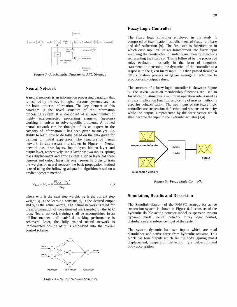
Neural Network
A neural network is an information processing paradigm that is inspired by the way biological nervous systems, such as the brain, process information. The key element of this paradigm is the novel structure of the information processing system. It is composed of a large number of highly interconnected processing elements (neurons) working in unison to solve specific problems. A trained neural network can be thought of as an expert in the category of information it has been given to analyze. An ability to learn how to do tasks based on the data given for training or initial experience. The structure of neural network in this research is shown in Figure 4. Neural network has three layers, input layer, hidden layer and output layer, respectively. Input layer has two inputs, sprung mass displacement and error system. Hidden layer has three neurons and output layer has one neuron. In order to train the weights of neural network the back propagation method is used uaing the following adaptation algorithm based on a gradient descent method.
k
adkk w
yyww
∂−∂
+=+)(
1 η (5)
where wk+1 is the next step weight, wk is the current step weight, η is the learning constant, yd is the desired output and ya is the actual output. The neural network is used for the approximation of the estimated mass needed by the AFC loop. Neural network training shall be accomplished in an off-line manner until satisfied tracking performance is achieved. Later, the fully trained neural network is implemented on-line as it is embedded into the overall control scheme.
hidden layer output layerinput layer
input 2
input 1
output
Figure 4 - Neural Network Structure
Fuzzy Logic Controller
The fuzzy logic controller employed in the study is composed of fuzzification, establishment of fuzzy rule base and defuzzification [9]. The first step is fuzzification in which crisp input values are transformed into fuzzy input involving the construction of suitable membership functions representing the fuzzy set. This is followed by the process of rules evaluation normally in the form of linguistic statements to determine the dynamics of the controller as a response to the given fuzzy input. It is then passed through a defuzzification process using an averaging technique to produce crisp output values. The structure of a fuzzy logic controller is shown in Figure 5. The seven Gaussian membership functions are used in fuzzification. Mamdani’s minimum operation rule is used as a fuzzy implication function, and centre of gravity method is used for defuzzification. The two inputs of the fuzzy logic controller are suspension deflection and suspension velocity while the output is represented by the force vector which shall become the input to the hydraulic actuator [1,4].
suspension deflection
suspension velocity
output
Figure 5 - Fuzzy Logic Controller
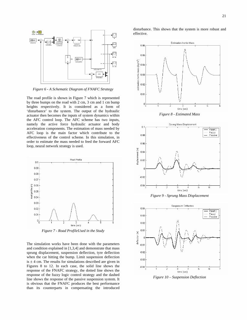
Simulation, Results and Discussion
The Simulink diagram of the FNAFC strategy for active suspension system is shown in Figure 6. It consists of the hydraulic double acting actuator model, suspension system dynamic model, neural network, fuzzy logic control, disturbances and reference input of the system. The system dynamic has two inputs which are road disturbance and active force from hydraulic actuator. This block has four outputs which are the body (sprung mass) displacement, suspension deflection, tyre deflection and body acceleration.
21
Figure 6 - A Schematic Diagram of FNAFC Strategy
The road profile is shown in Figure 7 which is represented by three bumps on the road with 2 cm, 3 cm and 1 cm bump heights respectively. It is considered as a form of ‘disturbance’ to the system. The output of the hydraulic actuator then becomes the inputs of system dynamics within the AFC control loop. The AFC scheme has two inputs, namely the active force hydraulic actuator and body acceleration components. The estimation of mass needed by AFC loop is the main factor which contribute to the effectiveness of the control scheme. In this simulation, in order to estimate the mass needed to feed the forward AFC loop, neural network strategy is used.
Figure 7 - Road ProfileUsed in the Study
The simulation works have been done with the parameters and condition explained in [1,3,4] and demonstrate that mass sprung displacement, suspension deflection, tyre deflection when the car hitting the bump. Limit suspension deflection is ± 4 cm. The results for simulations described are given in Figures 8 to 12. In each case, the solid line shows the response of the FNAFC strategy, the dotted line shows the response of the fuzzy logic control strategy and the dashed line shows the response of the passive suspension system. It is obvious that the FNAFC produces the best performance than its counterparts in compensating the introduced
disturbance. This shows that the system is more robust and effective.
Figure 8 - Estimated Mass
Figure 9 - Sprung Mass Displacement
Figure 10 – Suspension Deflection
22
Figure 11 – Sprung Mass Acceleration
Figure 12 – Tyre Deflection
Conclusion
The resulting control strategy known as fuzzy-neuro active force controller (FNAFC) has been shown to be robust and effective in controlling the suspension system. It was found that the active suspension system with fuzzy-neuro active force control gives better performance compared to the fuzzy logic and the passive suspension systems. All the four main parameters related to body displacement, suspension deflection, body mass acceleration, and tyre deflection have been desirably reduced through the control strategy. This may contribute to improved road handling and riding comfort of the automotive system.
Acknowledgments The authors would like to thank the Malaysian Ministry of Science and Technology and the Innovationt (MOSTI) and Universiti Teknologi Malaysia (UTM) for their continuous support in the research work. This research was fully supported by an IRPA grant (No. 03-02-06-0123EA001).
References
[1] Rao, M.V.C., Prahlad, V. 1997. A Tunable Fuzzy Logic Controller for Vehicle Active Suspension Systems, Fuzzy Sest and System, 11-21.
[2] D’Amato, F.J., Viassolo, D.E. 2000. Fuzzy Control for Active Suspensions, Mechatronics, (24):897-920.
[3] Alleyne, A., Liu, R., Wright, H. 1998. On the Limitations of Force Tracking Control for Hydraulic Active Suspensions. In the Proceedings of the American Control Conference, 43-47. Philadelphia, Pennsylvania.
[4] Barr, A.J.; Ray, J.I. 1996, Control of An Active Suspension Using Fuzzy Logic. In Proceedings of the Fifth IEEE International Conference on Fuzzy Systems, Vol. 1, 42 - 48.
[5] Campos, J., Lewis, F.L., Davis, L., Ikenaga, S. 2000. Backstepping Based Fuzzy Control of Active Vehicle Suspension Systems. In Proceedings of the American Control Conference, Vol. 6: 28-30.
[6] Hewit, J. R. and Burdess, J.R. 1981. Fast Dynamic Decoupled Control for Robotics Using Active Force Control, Transaction on Mechanism and Machine Theory, 16(5): 535-542.
[7] Mailah, M., Rahim, N.I.A. 2000. Intelligent Active Force Control of a Robot Arm Using Fuzzy Logic. In Proceedings of IEEE International Conference on Intelligent Systems and Technologies TENCON 2000, Vol. II: 291-297. Kuala Lumpur.
[8] Hussein, S.B, Jamaluddin, H., Mailah M. and Zalzala, A. 2000, A Hybrid Intelligent Active Force Controller For Robot Arm Using Evolutionary Neural Networks, In Proceedings of the International Conference on Evolutionary Computation (CEC 2000), 117-124. San Diego, USA.
[9] Negnevitsky, M. 2005, Artificial Intelligence: A Guide to Intelligent Systems, 2nd Edition, Addison Wesley.
CHAPTER 3
FUZZY-NEURO ACTIVE FORCE CONTROL OF A QUARTER CAR SUSPENSION SYSTEM
Gigih Priyandoko & Musa Mailah
Presented at International Conference on Robotics, Vision and Signal Processing
2005 (ROVISP05), Penang, May 2005
24
Particle Swarm Optimization Neural Network Based Modelling of Vehicle Suspension System
Gigih Priyandoko Musa Mailah Hishamuddin Jamaluddin
Department of Applied Mechanics,
Faculty of Mechanical Engineering, Universiti Teknologi Malaysia, 81310 Skudai, Johor Bahru, Malaysia e-mail: [email protected] [email protected] [email protected]
Abstract This paper presents a novel method for the modelling of a quarter car vehicle suspension system using a Neural Network (NN) technique incorporating Particle Swarm Optimization (PSO) method. The proposed neural network model is shown to be simple in topology and accurate in identification. The PSO element is able to speed up the convergence rate compared to the traditionally slow back-propagation (BP) learning algorithm that is typically employed as one of the most common supervised training methods in a multilayer NN configuration. The design and structure of the scheme based on this approach are adequately described and discussed with the input and output data acquired from a running quarter car test rig. Simulation results from the study show that the NN with PSO as learning method performs better than the BP learning algorithm in executing the proposed task. Keywords: Vehicle suspension, modelling, neural network, back-propagation, particle swarm optimization. 1. Introduction Modelling of a vehicle has been studied for a long time in order to design a high-performance vehicle controller. In the past, most vehicle models have been constructed analytically in the form of dynamic equations. A conventional vehicle model, however, suffers from structural complexity, long development time, and the difficulty of modelling the highly nonlinear terms and the measurement noise. In order to control a real vehicle beyond mere simulation, it is indispensable to model the vehicle quickly, easily, and accurately [1]. In paper [2], the authors develop a comprehensive nonlinear model of a vehicle suspension system. This model is derived using the standard kinematics and kinetics and takes into consideration a number of factors that are neglected in most existing models. Typical control strategies rely on linear and time-invariant models. Buckner et al. [3] use neural network that continually learns and estimates the nonlinear parameter variations of a quarter-car suspension model. This estimation algorithm becomes the foundation for an Intelligent Feedback Linearization controller for active vehicle suspensions. Billings et al. [4] demonstrated that NNs could be used successfully for the identification and control of non-linear dynamical systems. The most advantageous and distinguishing feature of NNs is their ability to learn. The network in the adaptive mode abstracts and generalizes the function character in the process of learning from
training patterns. The learning algorithm is an optimization method capable of finding weight coefficients and thresholds (learning rates) for a given neural network and a training set. The learning algorithm that is used most frequently is the backpropagation (BP) method. Although BP training has proved to be efficient in many applications, its convergence tends to be slow, and yields to suboptimal solutions [7]. To counter this problem, a particle swarm optimization (PSO) technique is proposed and used in the study. Generally, the PSO is characterized as a simple heuristic of a well balanced mechanism with flexibility to enhance and adapt to both global and local exploration abilities. It is a stochastic search technique with reduced memory requirement, computationally effective and easier to implement [9]. The paper is organized as follows: Section II describes the dynamics of the vehicle suspension system while section III presents the structure of the NNs using BP learning algorithm. Section IV describes the Particle Swarm Optimization technique. The results of the simulation study are discussed and presented in section V. Finally, the paper is concluded in section VI.
2. Quarter Car Vehicle Suspension A standard assumption in the design and analysis of controllers for vehicle suspension system is that the vertical vehicle dynamics can be
25
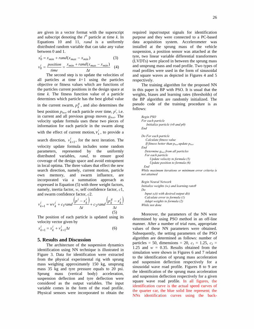
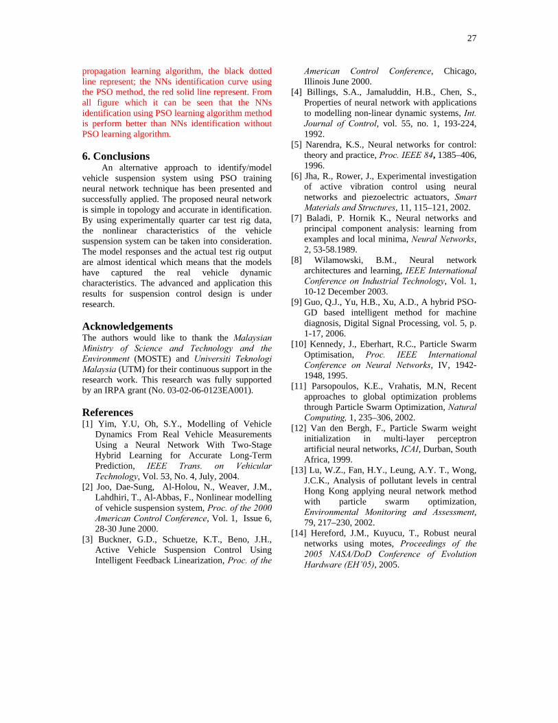
modelled using four independent quarter car suspension models. Quarter car models are simple but yet capture many important characteristics of the full model. Figure 1 depicts a typical two degree-of-freedom quarter car model of a passive suspension system, in which the single wheel and axle are connected to the car body through a passive spring-damper combination, while the tyre is modelled as a simple spring. Figure 2 shows the quarter car test rig. The parameters shown in Figure 1 are defined as follows:
ms: sprung mass mu: unsprung mass bs: damping coefficient ks: spring stiffness coefficient kt: tyre stiffness coefficient zs: displacement of the car body (sprung mass) zu: displacement of wheel (unsprung mass) zr: displacement of road zs–zu: suspension deflection zu – zr,: tyre deflection
sz& : velocity of sprung mass
uz& : velocity of unsprung mass
sz&& : acceleration of sprung mass
uz&& : acceleration of unsprung mass
3. Neural Network NN is basically a model structure and contains an algorithm for fitting the model to some given data. The network approach to modelling a plant uses a generic nonlinearity and allows all the parameters to be adjusted. In this way it can deal with a wide range of nonlinearities. Learning is the procedure of training the NN to represent the dynamics of a plant. The NN is placed in parallel with the plant and the error between the output of the system and the network output, the prediction error, is used as the training signal. NNs have a potential for intelligent control systems because they can learn and adapt, approximate nonlinear functions, suited for parallel and distributed processing, and they naturally model multivariable systems. The advantageous and distinguishing feature of NNs is their ability to learn. The learning algorithm is an optimization method capable of finding weight coefficients and learning rate for a given NNs and a training set. This algorithm is based on minimizing the error of the NNs output compared to the required output. The required function is specified by the training set. The error of network E relative to the training set is defined as the sum of the partial errors of network Ek relative to the individual
training patterns and depends on network configuration w:
( )∑ ∑= =
−==p
k
p
kkkk dOee
1 1
221 (1)
where p is number of available patterns, ek is partial network error, Ok is output of neural networks, dk is teach data or desired output. Updating the weights of each layer using BP method in time t > 0 is calculated in order to minimize error as follows [8]:
( ))2()1()1()1(
)1()1()(
−−−+∂
−∂=−∆
−∆+−=
twtwwtEtw
twtwtw
jkjkjk
jk
jkjkjk
βα
(2) where 0 < α < 1 is the learning rate, β is the momentum. The speed of training is dependent on the set constant α. If a low value is set, the network weights react very slowly. On the contrary, a high value is set the algorithm fails. Therefore, the parameter α is set experimentally. The structure of the multilayer NN used in the study consists of the input, output and hidden layers. The input layer has three inputs represented by the road profile, sprung mass acceleration and suspension deflection. Output layer has two outputs, namely the sprung mass acceleration and suspension deflection. Every output neuron uses a linear activation function. Hidden layer have three neurons and each neuron uses sigmoid bipolar activation. 4. Particle Swarm Optimization The PSO idea was originally introduced by Kennedy et al. in 1995 as a technique through individual improvement plus population cooperation and competition, which is based on the simulation of simplified social model, such as bird flocking, fish schooling and the swarm theory. Nowadays PSO has gained much attention and wide applications in various fields [10-12]. The basic PSO algorithm consists of three steps, namely, generating particles’ positions and velocities, velocity update, and position update. Here, a particle refers to a point in the design space that changes its position from one move (iteration) to another based on velocity updates. First, the positions, i
kx , and velocities, ikv , of the
initial swarm of particles are randomly generated using upper and lower bounds on the design variables values, minx and maxx , as expressed in Equations (3) and (4). The positions and velocities
26
are given in a vector format with the superscript and subscript denoting the ith particle at time k. In Equations 10 and 11, rand is a uniformly distributed random variable that can take any value between 0 and 1.
)(0 minmaxmini xxrandxx −+= (3)
txxrandx
timepositionv minmaxmini
∆−+
==)(
0 (4)
The second step is to update the velocities of all particles at time k+1 using the particles objective or fitness values which are functions of the particles current positions in the design space at time k. The fitness function value of a particle determines which particle has the best global value in the current swarm, g
kp , and also determines the best position pbest of each particle over time, pi, i.e. in current and all previous group moves gbest. The velocity update formula uses these two pieces of information for each particle in the swarm along with the effect of current motion, i
kv , to provide a
search direction, ikv 1+ , for the next iteration. The
velocity update formula includes some random parameters, represented by the uniformly distributed variables, rand, to ensure good coverage of the design space and avoid entrapment in local optima. The three values that effect the new search direction, namely, current motion, particle own memory, and swarm influence, are incorporated via a summation approach as expressed in Equation (5) with three weight factors, namely, inertia factor, w, self confidence factor, c1, and swarm confidence factor, c2.
( ) ( )t
xprandc
txp
randcwvvik
gk
ik
iik
ik ∆
−+
∆
−+=+ 211
(5) The position of each particle is updated using its velocity vector given by
tvxx ik
ik
ik ∆+= ++ 11 (6)
5. Results and Discussion The architecture of the suspension dynamics identification using NN technique is illustrated in Figure 3. Data for identification were extracted from the physical experimental rig with sprung mass weighing approximately 150 kg, unsprung mass 35 kg and tyre pressure equals to 20 psi. Sprung mass (vertical body) acceleration, suspension deflection and tyre deflection were considered as the output variables. The input variable comes in the form of the road profile. Physical sensors were incorporated to obtain the
required input/output signals for identification purpose and they were connected to a PC-based data acquisition system. Accelerometer was installed at the sprung mass of the vehicle suspension, a position sensor was attached at the tyre, two linear variable differential transformers (LVDTs) were placed in between the sprung mass and unsprung mass and road profile. Two types of road profiles were used in the form of sinusoidal and square waves as depicted in Figures 4 and 5 respectively. The training algorithm for the proposed NN in this paper is BP with PSO. It is usual that the weights, biases and learning rates (thresholds) of the BP algorithm are randomly initialized. The pseudo code of the training procedure is as follows:
Begin PSO For each particle Initialize particle (v0 and p0) End Do For each particle Calculate fitness value If fitness better than pbest update pbest End Determine gbest from all particles For each particle Update velocity to formula (5) Update position to formula (6) End While maximum iterations or minimum error criteria is not attained Begin Neural Network Initialize weights (wi) and learning rateθ Do Input xi(t) with desired output d(t) Calculate error to formula (1) Adapt weights to formula (2) While not done
Moreover, the parameters of the NN were
determined by using PSO method in an off-line manner. After a number of trial runs, appropriate values of these NN parameters were obtained. Subsequently, the setting parameters of the PSO algorithm are determined as follows: number of particles = 50, dimensions = 20, c1 = 1.25, c2 = 1.25 and w = 0.35. Results obtained from the simulation were shown in Figures 6 and 7 related to the identification of sprung mass acceleration and suspension deflection respectively for a sinusoidal wave road profile. Figures 8 to 9 are the identification of the sprung mass acceleration and suspension deflection respectively for a given square wave road profile. In all figures, the identification curve is the actual speed curves of the quarter car, the blue solid line represent; the NNs identification curves using the back-
27
propagation learning algorithm, the black dotted line represent; the NNs identification curve using the PSO method, the red solid line represent. From all figure which it can be seen that the NNs identification using PSO learning algorithm method is perform better than NNs identification without PSO learning algorithm. 6. Conclusions An alternative approach to identify/model vehicle suspension system using PSO training neural network technique has been presented and successfully applied. The proposed neural network is simple in topology and accurate in identification. By using experimentally quarter car test rig data, the nonlinear characteristics of the vehicle suspension system can be taken into consideration. The model responses and the actual test rig output are almost identical which means that the models have captured the real vehicle dynamic characteristics. The advanced and application this results for suspension control design is under research. Acknowledgements The authors would like to thank the Malaysian Ministry of Science and Technology and the Environment (MOSTE) and Universiti Teknologi Malaysia (UTM) for their continuous support in the research work. This research was fully supported by an IRPA grant (No. 03-02-06-0123EA001). References [1] Yim, Y.U, Oh, S.Y., Modelling of Vehicle
Dynamics From Real Vehicle Measurements Using a Neural Network With Two-Stage Hybrid Learning for Accurate Long-Term Prediction, IEEE Trans. on Vehicular Technology, Vol. 53, No. 4, July, 2004.
[2] Joo, Dae-Sung, Al-Holou, N., Weaver, J.M., Lahdhiri, T., Al-Abbas, F., Nonlinear modelling of vehicle suspension system, Proc. of the 2000 American Control Conference, Vol. 1, Issue 6, 28-30 June 2000.
[3] Buckner, G.D., Schuetze, K.T., Beno, J.H., Active Vehicle Suspension Control Using Intelligent Feedback Linearization, Proc. of the
American Control Conference, Chicago, Illinois June 2000.
[4] Billings, S.A., Jamaluddin, H.B., Chen, S., Properties of neural network with applications to modelling non-linear dynamic systems, Int. Journal of Control, vol. 55, no. 1, 193-224, 1992.
[5] Narendra, K.S., Neural networks for control: theory and practice, Proc. IEEE 84, 1385–406, 1996.
[6] Jha, R., Rower, J., Experimental investigation of active vibration control using neural networks and piezoelectric actuators, Smart Materials and Structures, 11, 115–121, 2002.
[7] Baladi, P. Hornik K., Neural networks and principal component analysis: learning from examples and local minima, Neural Networks, 2, 53-58.1989.
[8] Wilamowski, B.M., Neural network architectures and learning, IEEE International Conference on Industrial Technology, Vol. 1, 10-12 December 2003.
[9] Guo, Q.J., Yu, H.B., Xu, A.D., A hybrid PSO-GD based intelligent method for machine diagnosis, Digital Signal Processing, vol. 5, p. 1-17, 2006.
[10] Kennedy, J., Eberhart, R.C., Particle Swarm Optimisation, Proc. IEEE International Conference on Neural Networks, IV, 1942-1948, 1995.
[11] Parsopoulos, K.E., Vrahatis, M.N, Recent approaches to global optimization problems through Particle Swarm Optimization, Natural Computing, 1, 235–306, 2002.
[12] Van den Bergh, F., Particle Swarm weight initialization in multi-layer perceptron artificial neural networks, ICAI, Durban, South Africa, 1999.
[13] Lu, W.Z., Fan, H.Y., Leung, A.Y. T., Wong, J.C.K., Analysis of pollutant levels in central Hong Kong applying neural network method with particle swarm optimization, Environmental Monitoring and Assessment, 79, 217–230, 2002.
[14] Hereford, J.M., Kuyucu, T., Robust neural networks using motes, Proceedings of the 2005 NASA/DoD Conference of Evolution Hardware (EH’05), 2005.
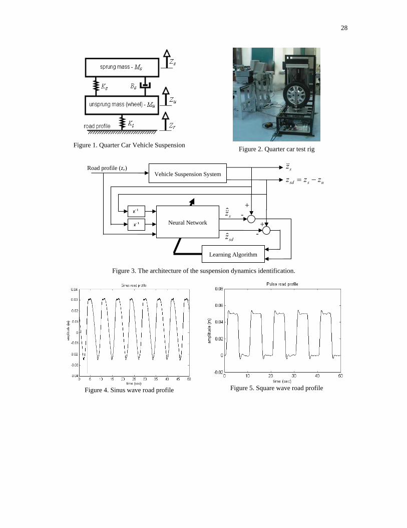
28
Figure 1. Quarter Car Vehicle Suspension
Figure 2. Quarter car test rig
Figure 3. The architecture of the suspension dynamics identification.
Figure 4. Sinus wave road profile
Figure 5. Square wave road profile
Vehicle Suspension SystemRoad profile (zr)
Neural Network
Learning Algorithm
sz&&
ussd zzz −=
+ -
+ -
sz&&
sdz
z- 1
z- 1
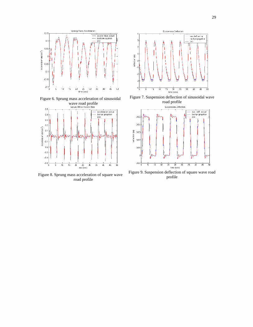
29
Figure 6. Sprung mass acceleration of sinusoidal
wave road profile
Figure 7. Suspension deflection of sinusoidal wave
road profile
Figure 8. Sprung mass acceleration of square wave
road profile
Figure 9. Suspension deflection of square wave road
profile
CHAPTER 4
PARTICLE SWARM OPTIMIZATION NEURAL NETWORK BASED MODELLING OF VEHICLE SUSPENSION SYSTEM
Gigih Priyandoko, Musa Mailah & Hishamuddin Jamaluddin
Presented at Regional Conference on Engineering and Science 2006 (RCPES06),
UTM Skudai, Jun 2006
31
SIMULATION OF SUSPENSION SYSTEM WITH ADAPTIVE FUZZY ACTIVE FORCE CONTROL
Priyandoko G. & Mailah M.
Department of Applied Mechanics, Faculty of Mechanical Engineering, Universiti Teknologi Malaysia, 81310 Skudai, Johor, Malaysia
E-mail: [email protected] and [email protected]
Abstract This paper presents the design of a control technique applied to an active suspension system of a quarter car model using adaptive fuzzy (AF) logic and active force control (AFC) technique. The overall control system comprises three loops: the inner actuator control loop employing a classic proportional-plus-integral (PI) controller for force tracking control of the hydraulic actuator, AFC loop using an AF element to estimate the mass needed to compensate for the disturbances and the outer positional control loop utilising a second AF controller to compute the optimum target force. The performance of the proposed control method was then simulated, evaluated and later compared to examine the effectiveness of the system in suppressing the undesirable effects of the suspension system. It was found that the active suspension system with Adaptive Fuzzy Active Force Control (AF-AFC) yields superior performance compared to the AF system without AFC and the passive counterpart. Keywords: Active suspension, quarter car model, adaptive fuzzy, active force control. 1. INTRODUCTION There are many mechanical systems in which it is necessary to provide isolation of one part form disturbance at another part. For example, the passenger of a car must be isolated from the car body vibrations when a car hitting a bump or hole.
In the conventional passive suspension system, the mass-spring-damper parameters are generally fixed, and they are chosen based on the design requirements of the vehicles. The suspension has the ability to store energy in the spring and to dissipate it through the damper. When a spring supports a load, it will compress until the force produced by the compression is equal to the load force. If some other forces then disturb the load, then it the load will oscillate up and down around its original position for some time. Passive suspension utilizing mechanical springs and dampers is known to have the limitations of vibration isolation and lack of attitude control of the vehicle body. To solve these problems, many researchers have studied various semi-active and active suspensions both theoretically and experimentally [1,2].
Active suspension differs from the conventional passive suspension in its ability to inject energy into the system. In an active suspension system, an actuator is attached in parallel with both a spring and a shock absorber. The main advantage of employing an active suspension is the associated adaptation potential where the suspension characteristic can be adjusted while driving to match the profile of the road being traversed. The active suspension system should be able to provide different behavioural characteristics depending upon various road conditions. The basic idea in active control of suspensions is to use an active element (the actuator) to apply a desired force between the car body and the wheel axle. This desired force is computed by the car's control unit to achieve certain performance objectives under external disturbances, e.g., passenger comfort under road imperfections [3].
Modern control and nonlinear control theory has been employed to design the controller for the active suspension system, for examples LQR [4], H∞ [5], nonlinear controller [6] and adaptive control [7]. However, an accurate system model must be provided before the controller can be developed. The other hand, the model-free fuzzy logic control strategy has attracted the attention of the designers [8-9]. Fuzzy
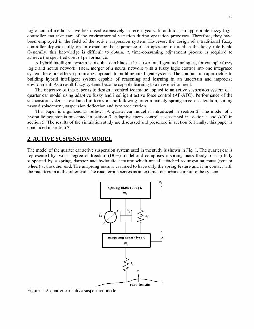
32
logic control methods have been used extensively in recent years. In addition, an appropriate fuzzy logic controller can take care of the environmental variation during operation processes. Therefore, they have been employed in the field of the active suspension system. However, the design of a traditional fuzzy controller depends fully on an expert or the experience of an operator to establish the fuzzy rule bank. Generally, this knowledge is difficult to obtain. A time-consuming adjustment process is required to achieve the specified control performance.
A hybrid intelligent system is one that combines at least two intelligent technologies, for example fuzzy logic and neural network. Then, merger of a neural network with a fuzzy logic control into one integrated system therefore offers a promising approach to building intelligent systems. The combination approach is to building hybrid intelligent system capable of reasoning and learning in an uncertain and imprecise environment. As a result fuzzy systems become capable learning to a new environment.
The objective of this paper is to design a control technique applied to an active suspension system of a quarter car model using adaptive fuzzy and intelligent active force control (AF-AFC). Performance of the suspension system is evaluated in terms of the following criteria namely sprung mass acceleration, sprung mass displacement, suspension deflection and tyre acceleration.
This paper is organized as follows. A quarter-car model is introduced in section 2. The model of a hydraulic actuator is presented in section 3. Adaptive fuzzy control is described in section 4 and AFC in section 5. The results of the simulation study are discussed and presented in section 6. Finally, this paper is concluded in section 7. 2. ACTIVE SUSPENSION MODEL The model of the quarter car active suspension system used in the study is shown in Fig. 1. The quarter car is represented by two a degree of freedom (DOF) model and comprises a sprung mass (body of car) fully supported by a spring, damper and hydraulic actuator which are all attached to unsprung mass (tyre or wheel) at the other end. The unsprung mass is assumed to have only the spring feature and is in contact with the road terrain at the other end. The road terrain serves as an external disturbance input to the system.
sprung mass (body), ms
unsprung mass (tyre), mu
ks
kt
fabs
zs
zu
road terrain
zr
Figure 1: A quarter car active suspension model.
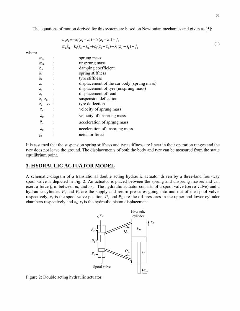
33
The equations of motion derived for this system are based on Newtonian mechanics and given as [5]:
arutussussuu
aussussss
)()()()()(
fzzkzzbzzkzmfzzbzzkzm
−−−−+−=+−−−−=
&&&&
&&&& (1)
where ms : sprung mass mu : unsprung mass bs : damping coefficient ks : spring stiffness kt : tyre stiffness zs : displacement of the car body (sprung mass) zu : displacement of tyre (unsprung mass) zr : displacement of road zs–zu : suspension deflection zu – zr : tyre deflection
sz& : velocity of sprung mass uz& : velocity of unsprung mass
sz&& : acceleration of sprung mass uz&& : acceleration of unsprung mass
fa : actuator force It is assumed that the suspension spring stiffness and tyre stiffness are linear in their operation ranges and the tyre does not leave the ground. The displacements of both the body and tyre can be measured from the static equilibrium point. 3. HYDRAULIC ACTUATOR MODEL A schematic diagram of a translational double acting hydraulic actuator driven by a three-land four-way spool valve is depicted in Fig. 2. An actuator is placed between the sprung and unsprung masses and can exert a force fa in between ms and mu. The hydraulic actuator consists of a spool valve (servo valve) and a hydraulic cylinder. Ps and Pr are the supply and return pressures going into and out of the spool valve, respectively, xv is the spool valve position, Pu and PL are the oil pressures in the upper and lower cylinder chambers respectively and xw-xc is the hydraulic piston displacement.
Pu
PL
Qu
QL
xc
xw
xv
Pr
Pr
Ps
Spool valve
Hydraulic cylinder
Figure 2: Double acting hydraulic actuator.
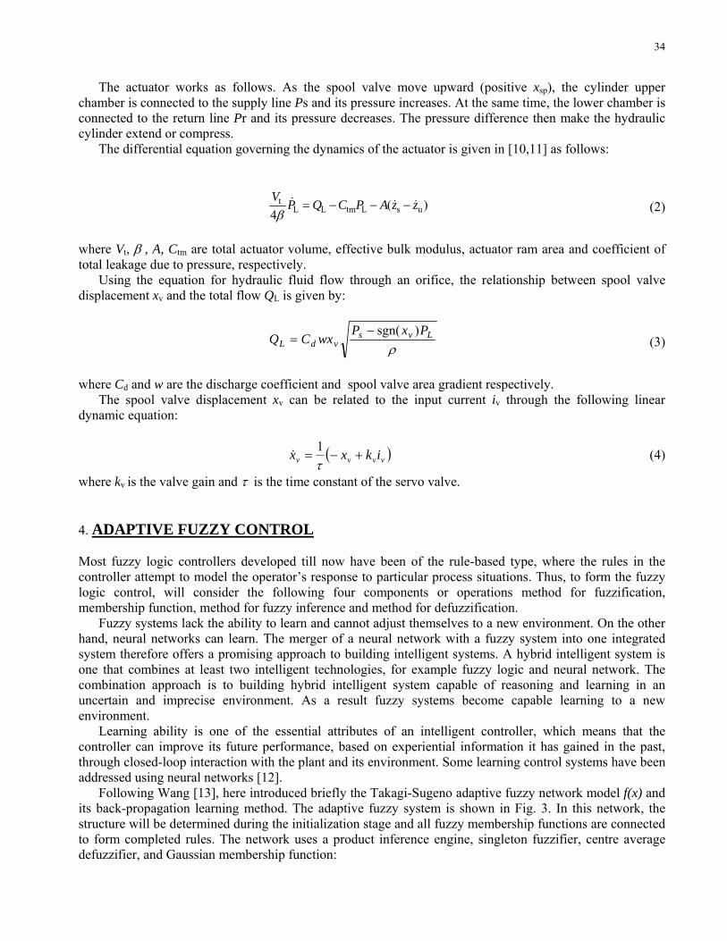
34
The actuator works as follows. As the spool valve move upward (positive xsp), the cylinder upper chamber is connected to the supply line Ps and its pressure increases. At the same time, the lower chamber is connected to the return line Pr and its pressure decreases. The pressure difference then make the hydraulic cylinder extend or compress.
The differential equation governing the dynamics of the actuator is given in [10,11] as follows:
)(4 usLtmLL
t zzAPCQPV&&& −−−=
β (2)
where Vt, β , A, Ctm are total actuator volume, effective bulk modulus, actuator ram area and coefficient of total leakage due to pressure, respectively.
Using the equation for hydraulic fluid flow through an orifice, the relationship between spool valve displacement xv and the total flow QL is given by:
ρLvs
vdLPxP
wxCQ)sgn(−
= (3)
where Cd and w are the discharge coefficient and spool valve area gradient respectively. The spool valve displacement xv can be related to the input current iv through the following linear dynamic equation:
( )vvvv ikxx +−=τ1
& (4)
where kv is the valve gain and τ is the time constant of the servo valve. 4. ADAPTIVE FUZZY CONTROL Most fuzzy logic controllers developed till now have been of the rule-based type, where the rules in the controller attempt to model the operator’s response to particular process situations. Thus, to form the fuzzy logic control, will consider the following four components or operations method for fuzzification, membership function, method for fuzzy inference and method for defuzzification.
Fuzzy systems lack the ability to learn and cannot adjust themselves to a new environment. On the other hand, neural networks can learn. The merger of a neural network with a fuzzy system into one integrated system therefore offers a promising approach to building intelligent systems. A hybrid intelligent system is one that combines at least two intelligent technologies, for example fuzzy logic and neural network. The combination approach is to building hybrid intelligent system capable of reasoning and learning in an uncertain and imprecise environment. As a result fuzzy systems become capable learning to a new environment.
Learning ability is one of the essential attributes of an intelligent controller, which means that the controller can improve its future performance, based on experiential information it has gained in the past, through closed-loop interaction with the plant and its environment. Some learning control systems have been addressed using neural networks [12].
Following Wang [13], here introduced briefly the Takagi-Sugeno adaptive fuzzy network model f(x) and its back-propagation learning method. The adaptive fuzzy system is shown in Fig. 3. In this network, the structure will be determined during the initialization stage and all fuzzy membership functions are connected to form completed rules. The network uses a product inference engine, singleton fuzzifier, centre average defuzzifier, and Gaussian membership function:
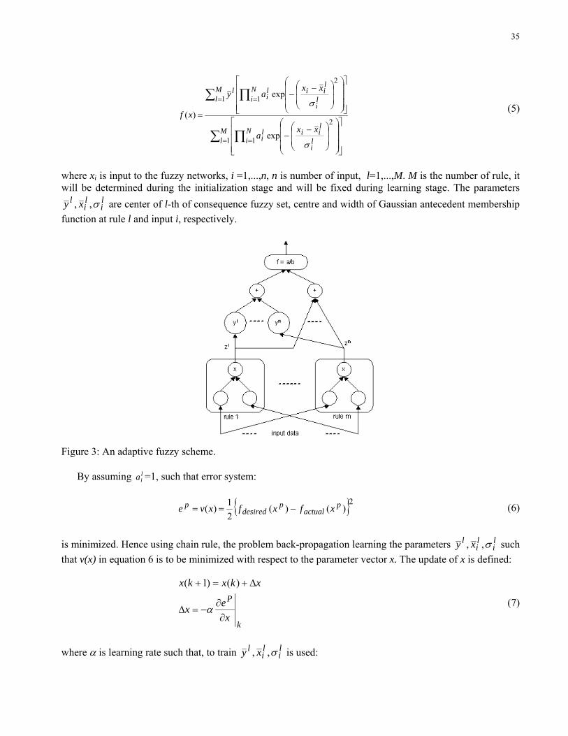
35
∑ ∏
∑ ∏
= =
= =
⎥⎥⎥
⎦
⎤
⎢⎢⎢
⎣
⎡
⎟⎟⎟
⎠
⎞
⎜⎜⎜
⎝
⎛
⎟⎟
⎠
⎞
⎜⎜
⎝
⎛ −−
⎥⎥⎥
⎦
⎤
⎢⎢⎢
⎣
⎡
⎟⎟⎟
⎠
⎞
⎜⎜⎜
⎝
⎛
⎟⎟
⎠
⎞
⎜⎜
⎝
⎛ −−
=
Ml
Ni l
i
liil
i
Ml
Ni l
i
liil
il
xxa
xxay
xf
1 1
2
1 1
2
exp
exp
)(
σ
σ (5)
where xi is input to the fuzzy networks, i =1,...,n, n is number of input, l=1,...,M. M is the number of rule, it will be determined during the initialization stage and will be fixed during learning stage. The parameters
li
li
l xy σ,, are center of l-th of consequence fuzzy set, centre and width of Gaussian antecedent membership function at rule l and input i, respectively.
Figure 3: An adaptive fuzzy scheme.
By assuming l
ia =1, such that error system:
2)()(21)( p
actualp
desiredp xfxfxve −== (6)
is minimized. Hence using chain rule, the problem back-propagation learning the parameters l
ili
l xy σ,, such that v(x) in equation 6 is to be minimized with respect to the parameter vector x. The update of x is defined:
k
P
xex
xkxkx
∂∂
−=∆
∆+=+
α
)()1(
(7)
where α is learning rate such that, to train l
ili
l xy σ,, is used:
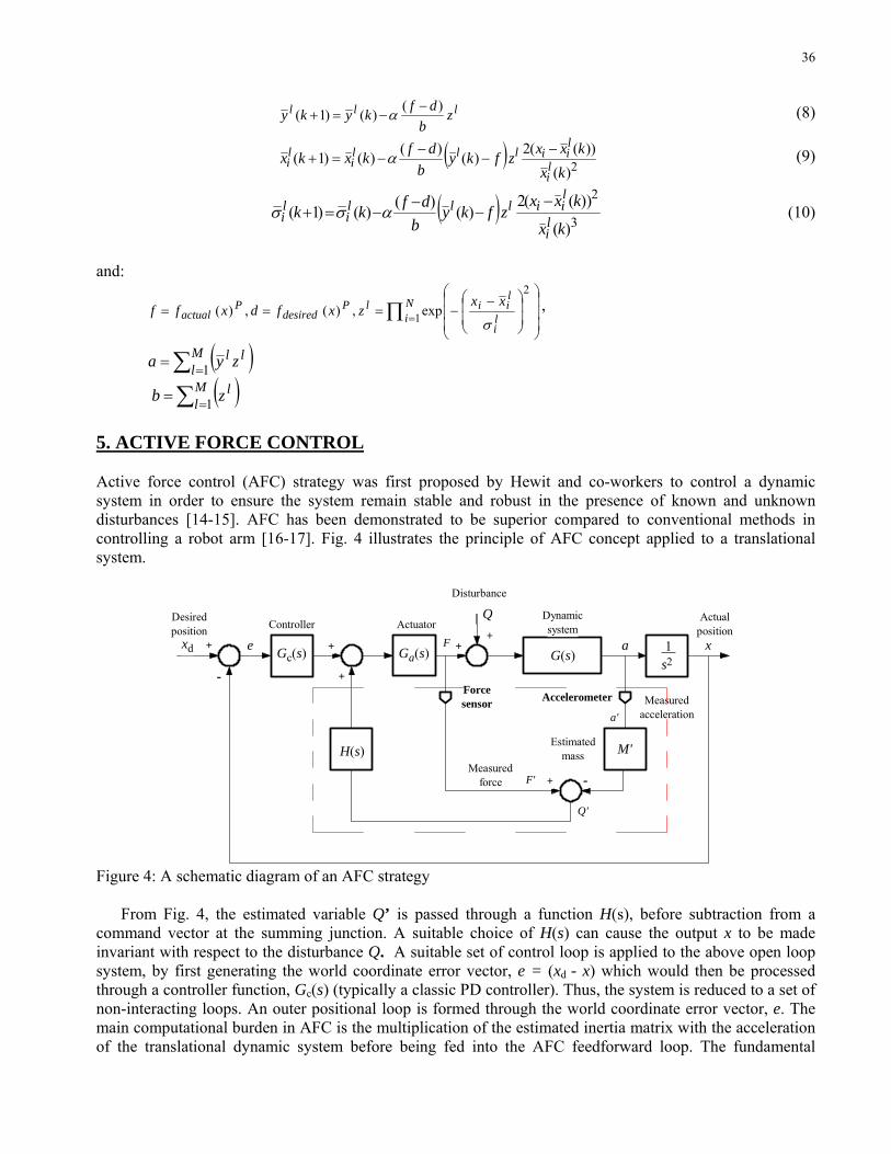
36
lll zb
dfkyky )()()1( −−=+ α (8)
( ) 2)())((2)()()()1(
kxkxxz fky
bdfkxkx l
i
liilll
ili
−−
−−=+ α (9)
( )3
2
)(
))((2)()()()1(
kx
kxxz fky
bdfkk
li
liilll
ili
−−
−−=+ ασσ (10)
and:
∏ = ⎟⎟⎟
⎠
⎞
⎜⎜⎜
⎝
⎛
⎟⎟
⎠
⎞
⎜⎜
⎝
⎛ −−=== N
i li
liilP
desiredP
actualxx
zxfdxff 1
2
exp,)(,)(σ
,
( )∑ == Ml
ll zya 1
( )∑ == Ml
lzb 1 5. ACTIVE FORCE CONTROL Active force control (AFC) strategy was first proposed by Hewit and co-workers to control a dynamic system in order to ensure the system remain stable and robust in the presence of known and unknown disturbances [14-15]. AFC has been demonstrated to be superior compared to conventional methods in controlling a robot arm [16-17]. Fig. 4 illustrates the principle of AFC concept applied to a translational system.
Ga(s) G(s)
M'H(s)
Q+F
Forcesensor Accelerometer
+ -
Q'
+
+
aGc(s) 1 s2
+
-
xd x+
F'
Disturbance
Dynamic systemActuatorController
Desiredposition
Actualposition
Estimatedmass
Measured force
Measuredaccelerationa'
e
Figure 4: A schematic diagram of an AFC strategy From Fig. 4, the estimated variable Q’ is passed through a function H(s), before subtraction from a command vector at the summing junction. A suitable choice of H(s) can cause the output x to be made invariant with respect to the disturbance Q. A suitable set of control loop is applied to the above open loop system, by first generating the world coordinate error vector, e = (xd - x) which would then be processed through a controller function, Gc(s) (typically a classic PD controller). Thus, the system is reduced to a set of non-interacting loops. An outer positional loop is formed through the world coordinate error vector, e. The main computational burden in AFC is the multiplication of the estimated inertia matrix with the acceleration of the translational dynamic system before being fed into the AFC feedforward loop. The fundamental
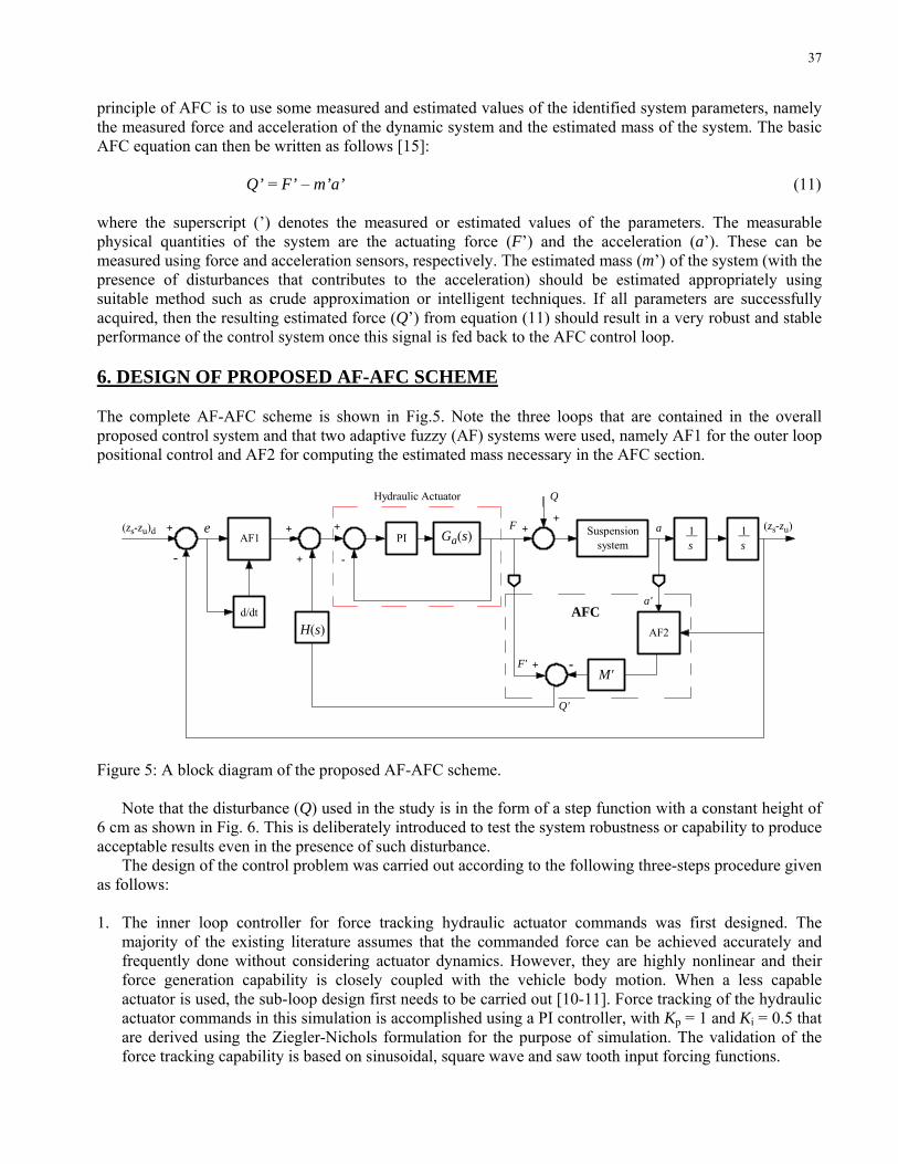
37
principle of AFC is to use some measured and estimated values of the identified system parameters, namely the measured force and acceleration of the dynamic system and the estimated mass of the system. The basic AFC equation can then be written as follows [15]: Q’ = F’ – m’a’ (11) where the superscript (’) denotes the measured or estimated values of the parameters. The measurable physical quantities of the system are the actuating force (F’) and the acceleration (a’). These can be measured using force and acceleration sensors, respectively. The estimated mass (m’) of the system (with the presence of disturbances that contributes to the acceleration) should be estimated appropriately using suitable method such as crude approximation or intelligent techniques. If all parameters are successfully acquired, then the resulting estimated force (Q’) from equation (11) should result in a very robust and stable performance of the control system once this signal is fed back to the AFC control loop. 6. DESIGN OF PROPOSED AF-AFC SCHEME The complete AF-AFC scheme is shown in Fig.5. Note the three loops that are contained in the overall proposed control system and that two adaptive fuzzy (AF) systems were used, namely AF1 for the outer loop positional control and AF2 for computing the estimated mass necessary in the AFC section.
Suspensionsystem
AF2H(s)
Q
+F
+ -
Q'
+
+
aAF1 1
s+
-
(zs-zu)d +
F'
Hydraulic Actuator
a'
e
M'
PI+
-
Ga(s)
d/dt
1 s
(zs-zu)
AFC
Figure 5: A block diagram of the proposed AF-AFC scheme.
Note that the disturbance (Q) used in the study is in the form of a step function with a constant height of 6 cm as shown in Fig. 6. This is deliberately introduced to test the system robustness or capability to produce acceptable results even in the presence of such disturbance.
The design of the control problem was carried out according to the following three-steps procedure given as follows:
1. The inner loop controller for force tracking hydraulic actuator commands was first designed. The
majority of the existing literature assumes that the commanded force can be achieved accurately and frequently done without considering actuator dynamics. However, they are highly nonlinear and their force generation capability is closely coupled with the vehicle body motion. When a less capable actuator is used, the sub-loop design first needs to be carried out [10-11]. Force tracking of the hydraulic actuator commands in this simulation is accomplished using a PI controller, with Kp = 1 and Ki = 0.5 that are derived using the Ziegler-Nichols formulation for the purpose of simulation. The validation of the force tracking capability is based on sinusoidal, square wave and saw tooth input forcing functions.
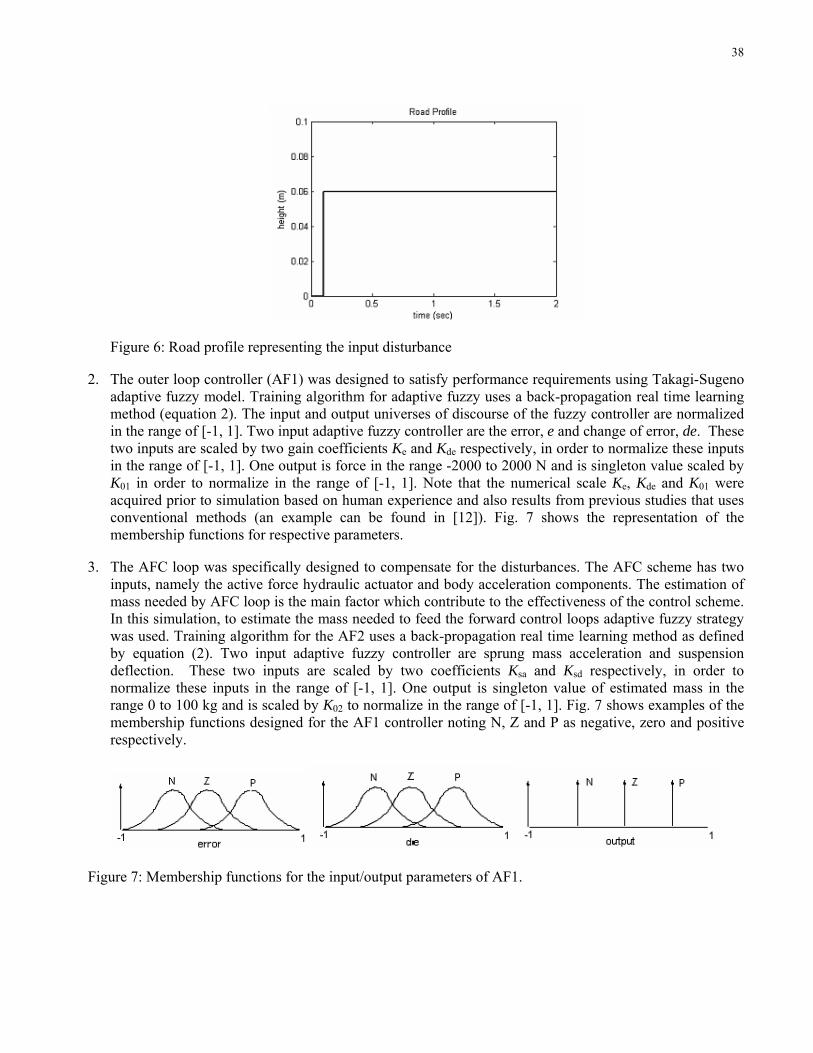
38
Figure 6: Road profile representing the input disturbance
2. The outer loop controller (AF1) was designed to satisfy performance requirements using Takagi-Sugeno adaptive fuzzy model. Training algorithm for adaptive fuzzy uses a back-propagation real time learning method (equation 2). The input and output universes of discourse of the fuzzy controller are normalized in the range of [-1, 1]. Two input adaptive fuzzy controller are the error, e and change of error, de. These two inputs are scaled by two gain coefficients Ke and Kde respectively, in order to normalize these inputs in the range of [-1, 1]. One output is force in the range -2000 to 2000 N and is singleton value scaled by K01 in order to normalize in the range of [-1, 1]. Note that the numerical scale Ke, Kde and K01 were acquired prior to simulation based on human experience and also results from previous studies that uses conventional methods (an example can be found in [12]). Fig. 7 shows the representation of the membership functions for respective parameters.
3. The AFC loop was specifically designed to compensate for the disturbances. The AFC scheme has two inputs, namely the active force hydraulic actuator and body acceleration components. The estimation of mass needed by AFC loop is the main factor which contribute to the effectiveness of the control scheme. In this simulation, to estimate the mass needed to feed the forward control loops adaptive fuzzy strategy was used. Training algorithm for the AF2 uses a back-propagation real time learning method as defined by equation (2). Two input adaptive fuzzy controller are sprung mass acceleration and suspension deflection. These two inputs are scaled by two coefficients Ksa and Ksd respectively, in order to normalize these inputs in the range of [-1, 1]. One output is singleton value of estimated mass in the range 0 to 100 kg and is scaled by K02 to normalize in the range of [-1, 1]. Fig. 7 shows examples of the membership functions designed for the AF1 controller noting N, Z and P as negative, zero and positive respectively.
Figure 7: Membership functions for the input/output parameters of AF1.
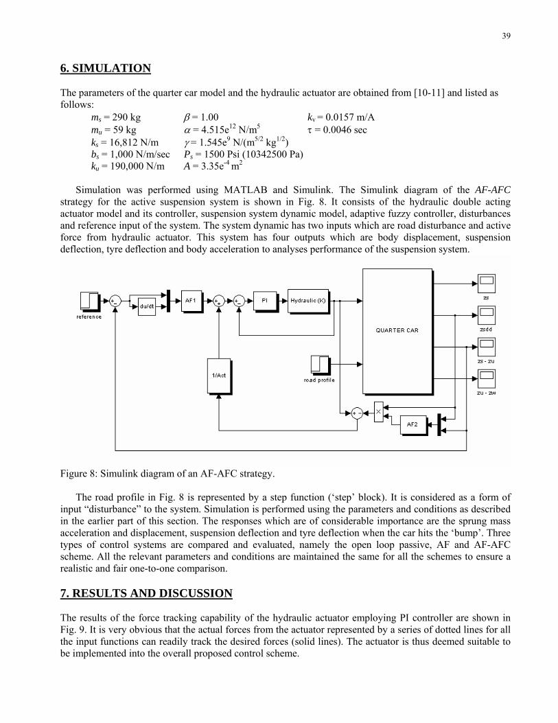
39
6. SIMULATION The parameters of the quarter car model and the hydraulic actuator are obtained from [10-11] and listed as follows:
ms = 290 kg β = 1.00 kv = 0.0157 m/A mu = 59 kg α = 4.515e12 N/m5 τ = 0.0046 sec ks = 16,812 N/m γ = 1.545e9 N/(m5/2 kg1/2) bs = 1,000 N/m/sec Ps = 1500 Psi (10342500 Pa) ku = 190,000 N/m A = 3.35e-4 m2
Simulation was performed using MATLAB and Simulink. The Simulink diagram of the AF-AFC
strategy for the active suspension system is shown in Fig. 8. It consists of the hydraulic double acting actuator model and its controller, suspension system dynamic model, adaptive fuzzy controller, disturbances and reference input of the system. The system dynamic has two inputs which are road disturbance and active force from hydraulic actuator. This system has four outputs which are body displacement, suspension deflection, tyre deflection and body acceleration to analyses performance of the suspension system.
Figure 8: Simulink diagram of an AF-AFC strategy.
The road profile in Fig. 8 is represented by a step function (‘step’ block). It is considered as a form of
input “disturbance” to the system. Simulation is performed using the parameters and conditions as described in the earlier part of this section. The responses which are of considerable importance are the sprung mass acceleration and displacement, suspension deflection and tyre deflection when the car hits the ‘bump’. Three types of control systems are compared and evaluated, namely the open loop passive, AF and AF-AFC scheme. All the relevant parameters and conditions are maintained the same for all the schemes to ensure a realistic and fair one-to-one comparison. 7. RESULTS AND DISCUSSION The results of the force tracking capability of the hydraulic actuator employing PI controller are shown in Fig. 9. It is very obvious that the actual forces from the actuator represented by a series of dotted lines for all the input functions can readily track the desired forces (solid lines). The actuator is thus deemed suitable to be implemented into the overall proposed control scheme.
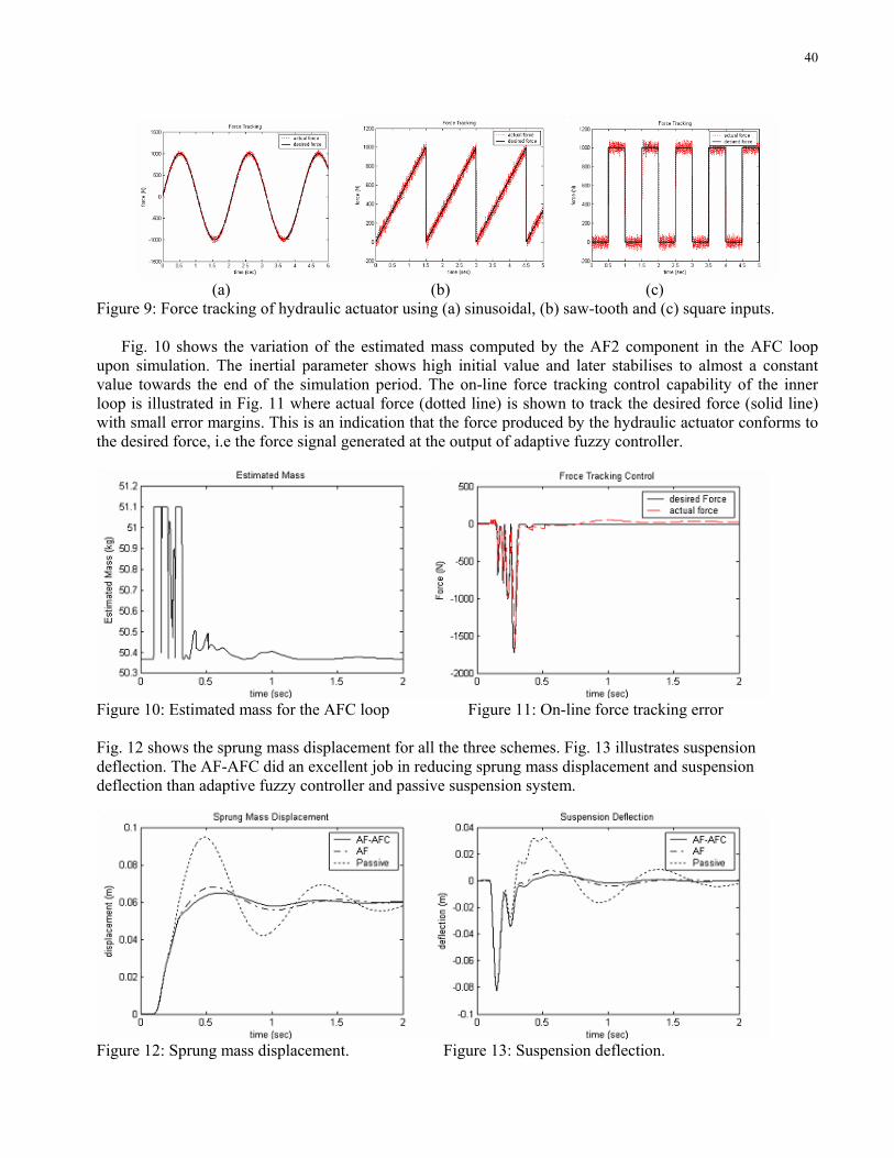
40
(a) (b) (c) Figure 9: Force tracking of hydraulic actuator using (a) sinusoidal, (b) saw-tooth and (c) square inputs. Fig. 10 shows the variation of the estimated mass computed by the AF2 component in the AFC loop upon simulation. The inertial parameter shows high initial value and later stabilises to almost a constant value towards the end of the simulation period. The on-line force tracking control capability of the inner loop is illustrated in Fig. 11 where actual force (dotted line) is shown to track the desired force (solid line) with small error margins. This is an indication that the force produced by the hydraulic actuator conforms to the desired force, i.e the force signal generated at the output of adaptive fuzzy controller.
Figure 10: Estimated mass for the AFC loop Figure 11: On-line force tracking error Fig. 12 shows the sprung mass displacement for all the three schemes. Fig. 13 illustrates suspension deflection. The AF-AFC did an excellent job in reducing sprung mass displacement and suspension deflection than adaptive fuzzy controller and passive suspension system.
Figure 12: Sprung mass displacement. Figure 13: Suspension deflection.
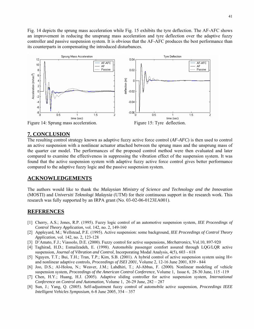
41
Fig. 14 depicts the sprung mass acceleration while Fig. 15 exhibits the tyre deflection. The AF-AFC shows an improvement in reducing the unsprung mass acceleration and tyre deflection over the adaptive fuzzy controller and passive suspension system. It is obvious that the AF-AFC produces the best performance than its counterparts in compensating the introduced disturbances.
Figure 14: Sprung mass acceleration. Figure 15: Tyre deflection. 7. CONCLUSION The resulting control strategy known as adaptive fuzzy active force control (AF-AFC) is then used to control an active suspension with a nonlinear actuator attached between the sprung mass and the unsprung mass of the quarter car model. The performances of the proposed control method were then evaluated and later compared to examine the effectiveness in suppressing the vibration effect of the suspension system. It was found that the active suspension system with adaptive fuzzy active force control gives better performance compared to the adaptive fuzzy logic and the passive suspension system. ACKNOWLEDGEMENTS The authors would like to thank the Malaysian Ministry of Science and Technology and the Innovation (MOSTI) and Universiti Teknologi Malaysia (UTM) for their continuous support in the research work. This research was fully supported by an IRPA grant (No. 03-02-06-0123EA001). REFERENCES [1] Cherry, A.S.; Jones, R.P. (1995). Fuzzy logic control of an automotive suspension system, IEE Proceedings of
Control Theory Application, vol. 142, no. 2, 149-160 [2] Appleyard, M.; Wellstead, P.E. (1995). Active suspension: some background, IEE Proceedings of Control Theory
Application, vol. 142, no. 2, 123-128 [3] D’Amato, F.J.; Viassolo, D.E. (2000). Fuzzy control for active suspensions, Mechatronics, Vol.10, 897-920 [4] Taghirad, H.D.; Esmailzadeh, E. (1998). Automobile passenger comfort assured through LQG/LQR active
suspension, Journal of Vibration and Control, Incorporating Modal Analysis, 4(5), 603 - 618 [5] Nguyen, T.T.; Bui, T.H.; Tran, T.P.; Kim, S.B. (2001). A hybrid control of active suspension system using H∞
and nonlinear adaptive controls, Proceedings of ISEI 2001, Volume 2, 12-16 June 2001, 839 - 844 [6] Joo, D.S.; Al-Holou, N.; Weaver, J.M.; Lahdhiri, T.; Al-Abbas, F. (2000). Nonlinear modeling of vehicle
suspension system, Proceedings of the American Control Conference, Volume 1, Issue 6, 28-30 June, 115 -119 [7] Chen, H.Y.; Huang, H.J. (2005). Adaptive sliding controller for active suspension system, International
Conference on Control and Automation, Volume 1, 26-29 June, 282 – 287 [8] Sun, J.; Yang, Q. (2005). Self-adjustment fuzzy control of automobile active suspension, Proceedings IEEE
Intelligent Vehicles Symposium, 6-8 June 2005, 354 – 357
42
[9] Mock, J. R.; Weeks, D. A.; Beno, J. H.; Nichols, S. P.; Bresie D. A.; Guenin, A. M. (2002). Dual Purpose Fuzzy Logic Controller for an Active Suspension System, SAE 2002 World Congress, Detroit, Michigan, March 4-7, 2002
[10] Alleyne, A.; Liu, R.; Wright, H. (1998). On the limitations of force tracking control for hydraulic active suspensions, Proceedings of the American Control Conference, Volume 1, 24-26 June, 43 – 47.
[11] Chantranuwathana, S.; Peng, H. (2004). Adaptive Robust Force Control for Vehicle Active Suspensions, International Journal of Adaptive Control and Signal Processing, 2004, 18:83-102
[12] Babuška, R. (2002). Neuro-fuzzy methods for modelling and identification, Abraham, A.; Jain, L.C.; Kacprzyk, J. (Editors), Recent Advances in Intelligent Paradigms and Applications, Springer-Verlag, Heidelberg, 161–186
[13] Wang, L-X. (1994). Adaptive Fuzzy Systems and Control, Prentice Hall, Englewood Cliffs, NJ [14] Hewit, J.R.; Moris, J.R. (1999). Disturbance observer control with estimation of the inertia matrix, Proceedings of
IEEE/ASME International Conference on Advanced Intelligent Mechatronics, 753-757 [15] Mailah, M. (1998). Intelligent Active Force Control of A Rigid Robot Arm Using Neural Network and Iterative
Learning Algorithms, Ph.D Thesis, University of Dundee, UK [16] Hussein, S.B.; Zalzala, A.M.S.; Jamaluddin, H.; Mailah, M. (2000). An evolutionary neural network controller for
intelligent active force control, Evolutionary Design and Manufacture, Parmee, I.C. (Editor), Springer Verlag, London, 352-362
[17] Mailah, M.; Rahim, N.I.A. (2000). Intelligent active force control of a robot arm using fuzzy logic, Proceedings of IEEE International Conference on Intelligent Systems and Technologies TENCON 2000, 291-296
CHAPTER 5
SIMULATION OF SUSPENSION SYSTEM WITH ADAPTIVE FUZZY ACTIVE FORCE CONTROL
Musa Mailah & Gigih Priyandoko
Published in International Journal on Simulation Modelling, Vol. 6, No. 1, March
2007, pp 25-36

45
Hybrid Control Scheme Incorporating AFC and Input Shaping Technique for A Suspension System
M. Z. Md Zain, G. Priyandoko, M. Mailah
Department of Applied Mechanics, Faculty of Mechanical Engineering, Universiti Teknologi Malaysia, MALAYSIA, email: [email protected] [email protected] [email protected]
Abstract - This paper describes an approach to investigate and develop a hybrid control scheme for vibration suppression of a suspension system. Initially, an active force control (AFC) scheme is developed for control of motion of the system. This is then extended to incorporate a feed-forward controller based on an input shaping (IS) technique for control of vibration suspension system of the system. Simulation results of the response of the suspension system with the control schemes are presented in time and frequency domains. The performance of the hybrid control scheme with AFC and IS control are assessed in terms of level of vibration reduction. Keywords - Active force control (AFC), input shaping (IS), suspension system.
1. INTRODUCTION For many years, automotive suspension has been designed using a coil or leaf spring in parallel with a viscous damper. The control of automotive suspensions is currently of great interest to both the academia and those in industries. Suspension design requires a compromise between the passenger comfort and good vehicle handling. To provide a good ride comfort, the suspension should be soft enough, but whereas good road holding requires stiff suspension. A good vehicle suspension should be able to minimize the vertical displacement and the acceleration of the body, however, in order to increase the passenger comfort, the sprung mass displacement need to be minimized.
In the conventional passive suspension system, the mass-spring-damper parameters are generally fixed, and they are chosen based on the design requirements of the vehicles. The suspension has the ability to store energy in the spring and to dissipate it through the damper. When a spring supports a load, it will compress until the force produced by the compression is equal to the load force. If some other forces disturb the load, then the load will oscillate up and down around its original position for some time. Passive suspension utilizing mechanical springs and dampers is known to have the limitations of vibration isolation and lack of attitude control of the vehicle body. To solve these problems, many researchers have studied various active and semi-active suspensions both theoretically and experimentally.
In semi active suspension systems, it still uses springs as the main form of support, however the dampers can be controlled. A semi active suspension
has the ability to change the damping characteristics of the shock absorbers without using any actuators.
Active suspension differs from the conventional passive suspension in its ability to inject energy into the system. In an active suspension system, an actuator is attached in parallel with both a spring and a shock absorber. To achieve the desired performance, actuator should generate the desired force in any direction, regardless of the relative velocity across it. The ability to control the energy from external source according to the environment provides better performance of suspension system. For this reason, the active suspension is widely investigated [2,3,6,7,8]. The objective of this research is to design a controller of active suspension system for reducing vertical body displacement, suspension deflection, tyre deflection and body acceleration using a hybrid control scheme (AFCIS) strategy.
This paper is organized as follows. A quarter car model is introduced in section 2. The model of a hydraulic actuator is presented in section 3. The relevant control schemes are then described in section 4 and the results of the simulation study discussed and presented in section 5. Finally, this paper is concluded in section 6.
2. DYNAMIC EQUATION OF AN ACTIVE SUSPENSION
The model of the quarter car active suspension system used is shown in Fig. 1. The quarter car is presented by a two degree-of-freedom model. The equations of motion for this system are given as [6]:
arutussussuu
aussussss
fzzkzzbzzkzmfzzbzzkzm
−−−−+−=+−−−−=
)()()()()(
&&&&
&&&& (1)
where ms , mu , bs, ks , kt , fa, zs, zu, zr, zs–zu, zu – zr, sz& ,
uz& are the sprung mass (body), unsprung mass (wheel), damping coefficient, spring stiffness, tyre stiffness, actuator force, displacement of the car body, displacement of wheel (unsprung), displacement of road, suspension deflection, tyre deflection, velocity of car body and velocity of wheel respectively.
By assuming that the suspension spring stiffness and tyre stiffness are linear in their operating ranges, the tyre does not leave the ground. The displacements of both the body and wheel can be measured from the static equilibrium point.
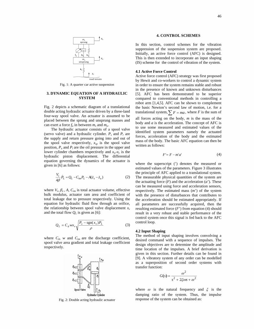
46
zs
zu
zr
fa bs ks
kt
mssprung
muunsprung
road terrain Fig. 1: A quarter car active suspension
3. DYNAMIC EQUATION OF A HYDRAULIC
SYSTEM
Fig. 2 depicts a schematic diagram of a translational double acting hydraulic actuator driven by a three-land four-way spool valve. An actuator is assumed to be placed between the sprung and unsprung masses and can exert a force fa in between ms and mu.
The hydraulic actuator consists of a spool valve (servo valve) and a hydraulic cylinder. Ps and Pr are the supply and return pressure going into and out of the spool valve respectively, xsp is the spool valve position, Pu and Pl are the oil pressure in the upper and lower cylinder chambers respectively and xw-xc is the hydraulic piston displacement. The differential equation governing the dynamics of the actuator is given in [6] as follows:
)(4 usLtmLL
t zzAPCQPV
&&& −−−=β
(2)
where Vt, βe , A, Ctm is total actuator volume, effective bulk modulus, actuator ram area and coefficient of total leakage due to pressure respectively. Using the equation for hydraulic fluid flow through an orifice, the relationship between spool valve displacement xv and the total flow QL is given as [6]:
ρLvs
vdLPxP
wxCQ)sgn(−
= (3)
where Cd, w and Ctm are the discharge coefficient, spool valve area gradient and total leakage coefficient respectively.
Fig. 2: Double acting hydraulic actuator
4. CONTROL SCHEMES
In this section, control schemes for the vibration suppression of the suspension system are proposed. Initially, an active force control (AFC) is designed. This is then extended to incorporate an input shaping (IS) scheme for the control of vibration of the system. 4.1 Active Force Control Active force control (AFC) strategy was first proposed by Hewit and co-workers to control a dynamic system in order to ensure the system remains stable and robust in the presence of known and unknown disturbances [5]. AFC has been demonstrated to be superior compared to conventional methods in controlling a robot arm [1,4,5]. AFC can be shown to complement the basic Newton’s second law of motion, i.e. for a translational system,∑ = maF , where F is the sum of all forces acting on the body, m is the mass of the body and a is the acceleration. The concept of AFC is to use some measured and estimated values of the identified system parameters namely the actuated forces, acceleration of the body and the estimated mass of the body. The basic AFC equation can then be written as follows:
''' amFF −= (4) where the superscript (’) denotes the measured or estimated values of the parameters. Figure 3 illustrates the principle of AFC applied to a translational system. The measurable physical quantities of the system are the actuating force (F) and the acceleration (a’). These can be measured using force and acceleration sensors, respectively. The estimated mass (m’) of the system with the presence of disturbances that contributes to the acceleration should be estimated appropriately. If all parameters are successfully acquired, then the resulting estimated force (F’) from equation (4) should result in a very robust and stable performance of the control system once this signal is fed back to the AFC control loop. 4.2 Input Shaping The method of input shaping involves convolving a desired command with a sequence of impulses. The design objectives are to determine the amplitude and time location of the impulses. A brief derivation is given in this section. Further details can be found in [9]. A vibratory system of any order can be modelled as a superposition of second order systems with transfer function:
22
2
2 ωξω
ω
++=
sssG )(
where ω is the natural frequency and ξ is the damping ratio of the system. Thus, the impulse response of the system can be obtained as:
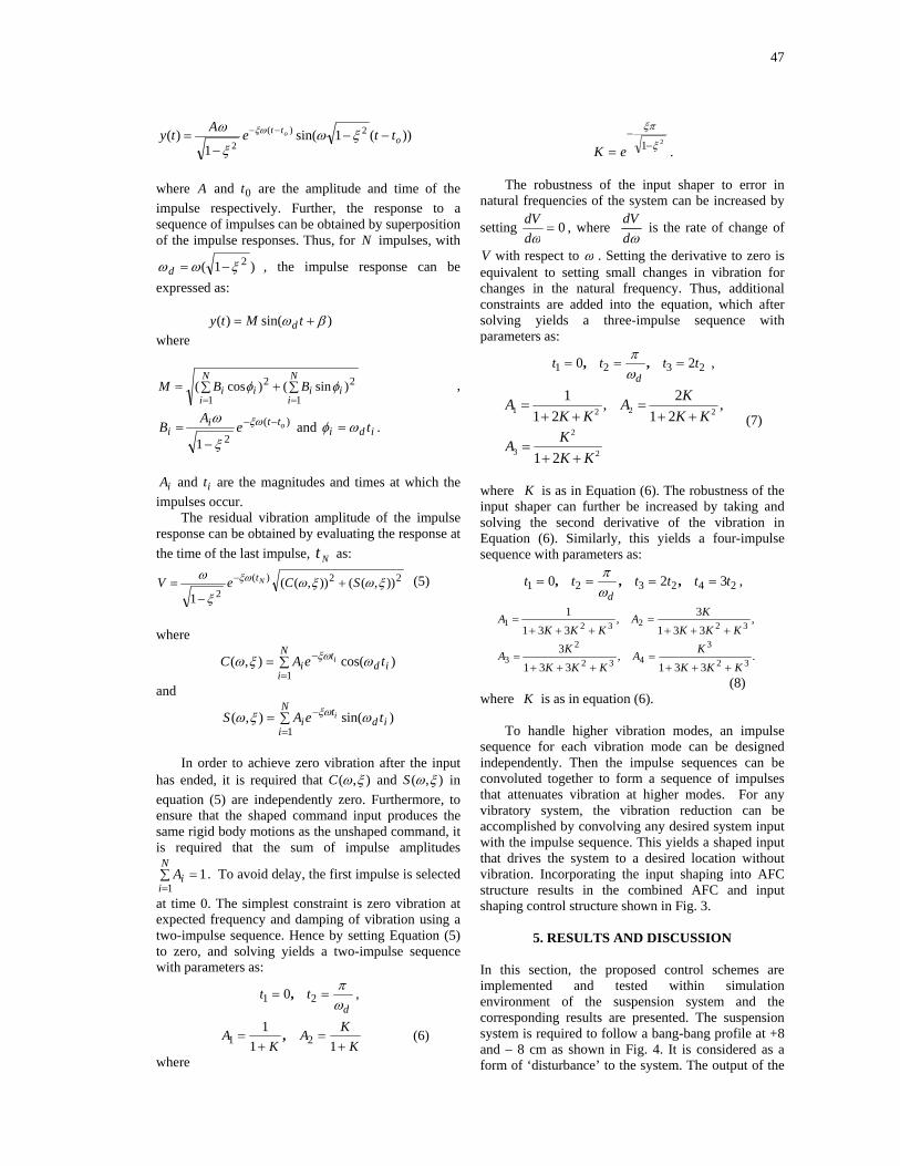
47
))(1sin(1
)( 2)(2 o
tt tteAty o −−−
= −− ξωξ
ω ξω
where A and 0t are the amplitude and time of the impulse respectively. Further, the response to a sequence of impulses can be obtained by superposition of the impulse responses. Thus, for N impulses, with
)1( 2ξωω −=d , the impulse response can be expressed as:
)sin()( βω += tMty d
where
∑ ∑+== =
N
i
N
iiiii BBM
1 1
22 )sin()cos( φφ ,
)(21
ottii e
AB −−
−= ξω
ξ
ω and idi tωφ = .
iA and it are the magnitudes and times at which the
impulses occur. The residual vibration amplitude of the impulse
response can be obtained by evaluating the response at the time of the last impulse, Nt as:
22)(2
)),(()),((1
ξωξωξ
ω ξω SCeV Nt +−
= − (5)
where
∑==
−N
iid
ti teAC i
1)cos(),( ωξω ξω
and
∑==
−N
iid
ti teAS i
1)sin(),( ωξω ξω
In order to achieve zero vibration after the input
has ended, it is required that ),( ξωC and ),( ξωS in equation (5) are independently zero. Furthermore, to ensure that the shaped command input produces the same rigid body motions as the unshaped command, it is required that the sum of impulse amplitudes
∑ ==
N
iiA
11. To avoid delay, the first impulse is selected
at time 0. The simplest constraint is zero vibration at expected frequency and damping of vibration using a two-impulse sequence. Hence by setting Equation (5) to zero, and solving yields a two-impulse sequence with parameters as:
dtt
ωπ
== 21 0, ,
K
KAK
A+
=+
=11
121 , (6)
where
21 ξ
ξπ
−−
= eK . The robustness of the input shaper to error in
natural frequencies of the system can be increased by
setting 0=ωd
dV , where ωd
dV is the rate of change of
V with respect to ω . Setting the derivative to zero is equivalent to setting small changes in vibration for changes in the natural frequency. Thus, additional constraints are added into the equation, which after solving yields a three-impulse sequence with parameters as:
2321 20 ttttd
=== ,,ωπ ,
2
2
3
2221
21
,212,
211
KKKA
KKKA
KKA
++=
++=
++=
(7)
where K is as in Equation (6). The robustness of the input shaper can further be increased by taking and solving the second derivative of the vibration in Equation (6). Similarly, this yields a four-impulse sequence with parameters as:
242321 320 ttttttd
==== ,,,ωπ ,
.331
,331
3
,331
3,3311
32
3
432
2
3
322321
KKKKA
KKKKA
KKKKA
KKKA
+++=
+++=
+++=
+++=
(8) where K is as in equation (6).
To handle higher vibration modes, an impulse sequence for each vibration mode can be designed independently. Then the impulse sequences can be convoluted together to form a sequence of impulses that attenuates vibration at higher modes. For any vibratory system, the vibration reduction can be accomplished by convolving any desired system input with the impulse sequence. This yields a shaped input that drives the system to a desired location without vibration. Incorporating the input shaping into AFC structure results in the combined AFC and input shaping control structure shown in Fig. 3.
5. RESULTS AND DISCUSSION
In this section, the proposed control schemes are implemented and tested within simulation environment of the suspension system and the corresponding results are presented. The suspension system is required to follow a bang-bang profile at +8 and – 8 cm as shown in Fig. 4. It is considered as a form of ‘disturbance’ to the system. The output of the
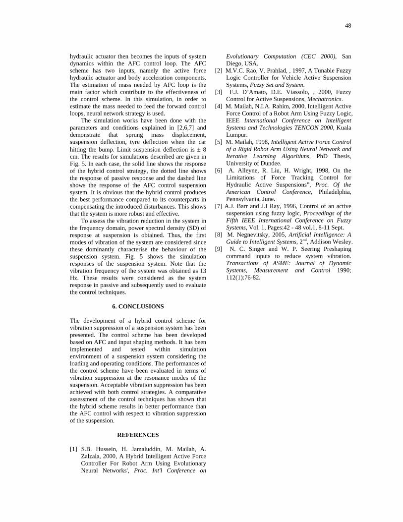
48
hydraulic actuator then becomes the inputs of system dynamics within the AFC control loop. The AFC scheme has two inputs, namely the active force hydraulic actuator and body acceleration components. The estimation of mass needed by AFC loop is the main factor which contribute to the effectiveness of the control scheme. In this simulation, in order to estimate the mass needed to feed the forward control loops, neural network strategy is used.
The simulation works have been done with the parameters and conditions explained in [2,6,7] and demonstrate that sprung mass displacement, suspension deflection, tyre deflection when the car hitting the bump. Limit suspension deflection is ± 8 cm. The results for simulations described are given in Fig. 5. In each case, the solid line shows the response of the hybrid control strategy, the dotted line shows the response of passive response and the dashed line shows the response of the AFC control suspension system. It is obvious that the hybrid control produces the best performance compared to its counterparts in compensating the introduced disturbances. This shows that the system is more robust and effective.
To assess the vibration reduction in the system in the frequency domain, power spectral density (SD) of response at suspension is obtained. Thus, the first modes of vibration of the system are considered since these dominantly characterise the behaviour of the suspension system. Fig. 5 shows the simulation responses of the suspension system. Note that the vibration frequency of the system was obtained as 13 Hz. These results were considered as the system response in passive and subsequently used to evaluate the control techniques.
6. CONCLUSIONS The development of a hybrid control scheme for vibration suppression of a suspension system has been presented. The control scheme has been developed based on AFC and input shaping methods. It has been implemented and tested within simulation environment of a suspension system considering the loading and operating conditions. The performances of the control scheme have been evaluated in terms of vibration suppression at the resonance modes of the suspension. Acceptable vibration suppression has been achieved with both control strategies. A comparative assessment of the control techniques has shown that the hybrid scheme results in better performance than the AFC control with respect to vibration suppression of the suspension.
REFERENCES [1] S.B. Hussein, H. Jamaluddin, M. Mailah, A.
Zalzala, 2000, A Hybrid Intelligent Active Force Controller For Robot Arm Using Evolutionary Neural Networks', Proc. Int'l Conference on
Evolutionary Computation (CEC 2000), San Diego, USA.
[2] M.V.C. Rao, V. Prahlad, , 1997, A Tunable Fuzzy Logic Controller for Vehicle Active Suspension Systems, Fuzzy Set and System.
[3] F.J. D’Amato, D.E. Viassolo, , 2000, Fuzzy Control for Active Suspensions, Mechatronics.
[4] M. Mailah, N.I.A. Rahim, 2000, Intelligent Active Force Control of a Robot Arm Using Fuzzy Logic, IEEE International Conference on Intelligent Systems and Technologies TENCON 2000, Kuala Lumpur.
[5] M. Mailah, 1998, Intelligent Active Force Control of a Rigid Robot Arm Using Neural Network and Iterative Learning Algorithms, PhD Thesis, University of Dundee.
[6] A. Alleyne, R. Liu, H. Wright, 1998, On the Limitations of Force Tracking Control for Hydraulic Active Suspensions”, Proc. Of the American Control Conference, Philadelphia, Pennsylvania, June.
[7] A.J. Barr and J.I Ray, 1996, Control of an active suspension using fuzzy logic, Proceedings of the Fifth IEEE International Conference on Fuzzy Systems, Vol. 1, Pages:42 - 48 vol.1, 8-11 Sept.
[8] M. Negnevitsky, 2005, Artificial Intelligence: A Guide to Intelligent Systems, 2nd, Addison Wesley.
[9] N. C. Singer and W. P. Seering Preshaping command inputs to reduce system vibration. Transactions of ASME: Journal of Dynamic Systems, Measurement and Control 1990; 112(1):76-82.

49
1/s1/s
displacementtranducer
actuator(Q)controller +++
+
+
+
-
-
disturbances
Active Force Control (AFC)
1/Q
estimatedmass
System Dynamic
actualtrack
forcesensor
accelerometer
desiredtrack
Fig. 3: A schematic diagram of AFC strategy
Fig. 4: Road profile
Time domain
Frequency domain (a) Sprung mass displacement
Time domain
Frequency domain
(b) Sprung mass acceleration
Input shaper
disturbance
50
Time domain
Frequency domain (c) Suspension deflection
Time domain
Frequency domain
(d) Tyre deflection
Fig. 5: System responses with AFC and input shaping control scheme
CHAPTER 6
HYBRID CONTROL SCHEME INCORPORATING AFC AND INPUT SHAPING TECHNIQUE FOR A SUSPENSION SYSTEM
Md Zarhamdy M Zain, Gigih Priyandoko & Musa Mailah
Accepted for presentation at SITIA07, Indonesia, 12-15 May 2007
52
Vehicle Active Suspension System Using Skyhook Adaptive Neuro Active Force Control
G. Priyandoko*, M. Mailah and H. Jamaluddin Intelligent Active Force Control Research Group Department of Applied Mechanics, Faculty of Mechanical Engineering, Universiti Teknologi Malaysia, Skudai, Johor, 81310 Malaysia Tel: +6075534562, Fax: +6075566159
E-mail: [email protected] E-mail: [email protected] E-mail: [email protected]
Abstract: This paper presents the practical design of a control technique applied to a vehicle active suspension system of a quarter car model using skyhook and adaptive neuro active force control (SANAFC). The overall control system essentially comprises four feedback control loops, namely the innermost PI control loop for the force tracking of the pneumatic actuator, intermediate skyhook and AFC control loops for the compensation of the disturbances and outermost PID control loop for the computation of the optimum target/commanded force. Neural networks (NN) with modified adaptive Levenberg-Marquardt learning algorithms were used to approximate the estimated mass and inverse dynamics of the pneumatic actuator in the AFC loop. A number of experiments were carried out on a physical test rig with hardware-in-the-loop configuration that fully incorporates the theoretical elements. The performances of the proposed control method were evaluated and compared to examine the effectiveness of the system in suppressing the vibration effect of the suspension system. It was found that both simulation and experimental results of the active suspension system with SANAFC scheme give better performance compared to the PID and passive counterparts. Keywords: Active suspension; quarter car model; pneumatic actuator; active force control; skyhook; neural network. Reference to this paper should be made as follows: Priyandoko, G., Mailah, M. and Jamaluddin, H. (2006) `Vehicle Active Suspension System Using Skyhook Neuro Active Force Control', Int. J. Intelligent Systems Technologies and Applications, Vol. X, No. Y, pp.000–000. Biographical notes: Gigih Priyandoko received his B.Eng. of Electrical Engineering from Brawijaya University of Indonesia and M.Sc. of Electrical Engineering from Bandung Institute of Technology (ITB), Indonesia. His current Ph.D. research is on intelligent vehicle active suspension using skyhook adaptive neuro active force control carried out at the Faculty of Mechanical Engineering, Universiti Teknologi Malaysia. His research interests include modelling, identification and design of controller using intelligent control methods. He is currently a lecturer in the Electrical Engineering, Faculty of Engineering, Universitas Widyagama, Malang, Indonesia. Musa Mailah acquired his B.Eng. (Hons.) in Mechanical Engineering in 1988 from the Universiti Teknologi Malaysia (UTM) and later M.Sc. (Mechatronics) and Ph.D. (Mechatronics and Control) degrees in 1992 and 1998 respectively from the University of Dundee, UK. He is currently an Associate Professor in the Department of Applied Mechanics, Faculty of Mechanical Engineering, Universiti Teknologi Malaysia. His research interests are applied mechatronics and intelligent active force control. Hishamuddin Jamaluddin received his B.Sc., M.Sc. and Ph.D. in the Department of Control Engineering, Sheffield University, UK. He is currently an Associate Professor in
53
the Department of Applied Mechanics, Faculty of Mechanical Engineering, Universiti Teknologi Malaysia (UTM), Johor, Malaysia. His research interests include non-linear system modeling, system identification, neural networks, adaptive fuzzy models, genetic algorithm, neuro-fuzzy and active force control.
1 Introduction
In many mechanical systems, it is often necessary and beneficial to isolate disturbance
forces. A clear example can be seen in an automotive system in which the passenger/s of
a car should ideally be isolated from vibration or shaking effects of the car’s body when
the car hits a bump or hole. In the conventional passive suspension system, the mass-
spring-damper elements are generally fixed, and are chosen based on the design
requirements of the vehicles. Passive suspension utilizing mechanical springs and
dampers is known to have the limitations of vibration isolation and lack of attitude
control of the vehicle body.
Active suspension differs from the conventional passive suspension in which an
actuator is attached in parallel with both spring and shock absorber to inject energy into
the system. The main advantage of employing an active suspension system is the
associated adaptation potential where the suspension characteristics can be adjusted
while driving to accommodate the profile of the road being traversed.
In any vehicle suspension system, there are a number of performance parameters
that need to be optimized. Four important parameters of considerable interest are: (i) ride
comfort which is related to acceleration sensed by passengers in the vehicle when
traversing a rough road surface, (ii) body motion which is associated with the pitch and
roll of the sprung mass created primarily by cornering and braking maneuvers, (iii) road
handling which can be related to the contact force between the tyres and road surface,
54
and (iv) suspension deflection which refers to the relative displacement between the
sprung and unsprung masses (Miller, 1988).
To tackle the problems in suspension systems, many researchers have studied
numerous active vehicle suspension strategies both theoretically and experimentally
(Alleyne and Hedrick, 1995; Lin and Kenellakopoulos, 1997; Ikenaga et. al., 1999;
Yoshimura et al., 2001; Huang and Lin, 2003). Many of these approaches are proposed
for complicated models with non-linearity and uncertainty. Numerical and experimental
results showed that such active suspension systems give relatively more satisfactory
performance, but need more increasing loads to achieve active control, compared with
the linear active suspension systems as reported in Yoshimura and Takagi (2004).
Intelligent control of suspension system was also proposed using fuzzy logic (D’Amato
and Viassolo, 2000) and neural network (Fu et al., 2005). Both methods use the
intelligent mechanisms as direct or main controllers and are found to be rather time
consuming to design and implement, particularly in acquiring the appropriate
membership functions plus inference mechanism (for fuzzy logic control) and training
parameters plus optimum network structure (for neural network control).
On the other hand, active force control (AFC) has been recognized to be simple,
robust and effective compared with conventional methods in controlling dynamical
systems, both in theory as well as practice (Hewit and Burdess, 1986; Hewit and Marouf,
1996; Mailah, 1998). The concept of AFC is to use some measured and estimated values
of the identified system parameters namely the actuated force, acceleration of the body
and estimated mass of the body. In practice, the estimated mass of the system (with the
presence of disturbances that contributes to the acceleration) should be appropriately
55
estimated using suitable methods such as the ones identified in Mailah (1998). In the
proposed study, an intelligent mechanism using neural network is incorporated into the
AFC loop serving not as the direct controller but merely as a means to approximate the
essential parameters necessary to trigger the control action.
The objective of this paper is to design a practical hardware-in-the-loop control
technique to reduce the sprung mass motion of a quarter car vehicle active suspension
system almost similar to the one proposed by Ikenaga (2000) but significantly
complemented with the proposed control and intelligent methods. The overall control
system comprises four loops: the innermost force tracking control loop employing a
classic PI controller for force tracking control of the pneumatic actuator; two
intermediate control loops with skyhook and AFC to compensate for the disturbances
containing the adaptive neural networks to compute on-line the estimated mass needed
and the inverse dynamics of the actuator; and the outer positional control loop utilizing a
PID controller to generate the target or commanded force. Performance of the vehicle
suspension system is evaluated in terms of its ability to significantly reduce the sprung
mass acceleration, sprung mass displacement, suspension deflection and tyre deflection
in the presence of road disturbances and given operating conditions.
This paper is organized as follows. A quarter-car model is introduced in section 2
followed by the pneumatic actuator model in section 3. The implementation of control
and intelligent methods is described in section 4. The experimental system is presented
in section 5 while the results are analysed and discussed in section 6. Finally, the paper is
concluded in section 7.

56
2 Dynamic Model of Active Suspension
The model of a quarter car active suspension system used is shown in Figure 1. The
quarter car is represented by a two degree-of-freedom model.
Figure 1 A quarter car vehicle active suspension
The equations of motion for this system are given as:
arutussussuu
aussussss
fzzkzzbzzkzmfzzbzzkzm
−−−−+−=+−−−−=
)()()()()(
&&&&
&&&& (1)
where ms , mu , bs , ks , kt , fa, zs, zu, zr, zs–zu, zu – zr, sz& , uz& are sprung mass, unsprung
mass, damping coefficient, spring stiffness, tyre stiffness, actuator force, displacement of
the sprung mass, displacement of unsprung mass, road profile, suspension deflection
(suspension travel), tyre deflection, velocity of sprung mass and velocity of unsprung
mass respectively.
3 Dynamic Model of a Pneumatic Actuator
Pneumatic actuators have the advantages of low cost, high power to weight ratio, ease of
maintenance, having a readily available and cheap power source (Hamiti et al., 1996).
But, pneumatic drives exhibit highly nonlinear characteristics due to the compressibility
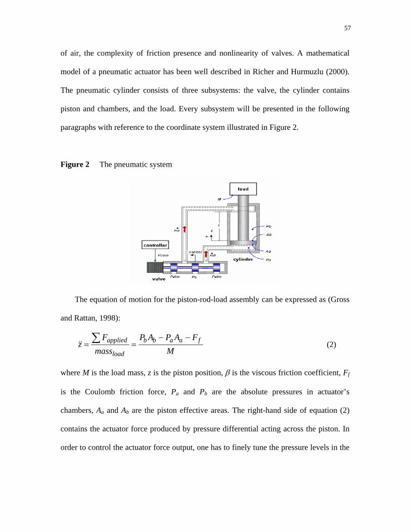
57
of air, the complexity of friction presence and nonlinearity of valves. A mathematical
model of a pneumatic actuator has been well described in Richer and Hurmuzlu (2000).
The pneumatic cylinder consists of three subsystems: the valve, the cylinder contains
piston and chambers, and the load. Every subsystem will be presented in the following
paragraphs with reference to the coordinate system illustrated in Figure 2.
Figure 2 The pneumatic system
The equation of motion for the piston-rod-load assembly can be expressed as (Gross
and Rattan, 1998):
M
FAPAPmass
Fz faabb
load
applied −−== ∑&& (2)
where M is the load mass, z is the piston position, β is the viscous friction coefficient, Ff
is the Coulomb friction force, Pa and Pb are the absolute pressures in actuator’s
chambers, Aa and Ab are the piston effective areas. The right-hand side of equation (2)
contains the actuator force produced by pressure differential acting across the piston. In
order to control the actuator force output, one has to finely tune the pressure levels in the
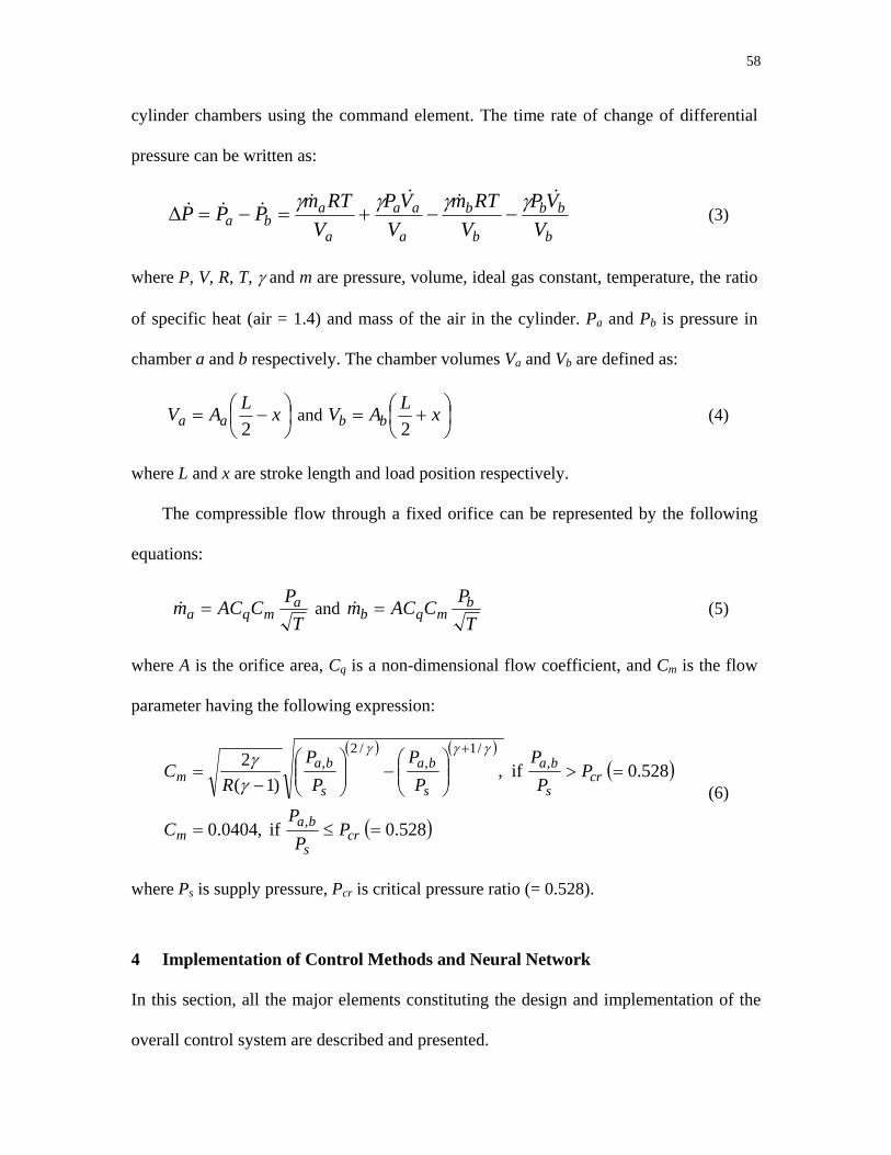
58
cylinder chambers using the command element. The time rate of change of differential
pressure can be written as:
b
bb
b
b
a
aa
a
aba V
VPV
RTmV
VPV
RTmPPP&&&&&&& γγγγ
−−+=−=∆ (3)
where P, V, R, T, γ and m are pressure, volume, ideal gas constant, temperature, the ratio
of specific heat (air = 1.4) and mass of the air in the cylinder. Pa and Pb is pressure in
chamber a and b respectively. The chamber volumes Va and Vb are defined as:
⎟⎠⎞
⎜⎝⎛ −= xLAV aa 2
and ⎟⎠⎞
⎜⎝⎛ += xLAV bb 2
(4)
where L and x are stroke length and load position respectively.
The compressible flow through a fixed orifice can be represented by the following
equations:
T
PCACm amqa =& and
TPCACm b
mqb =& (5)
where A is the orifice area, Cq is a non-dimensional flow coefficient, and Cm is the flow
parameter having the following expression:
( ) ( )( )
( ) 0.528 if ,0404.0
0.528 if ,)1(
2
,
,/1
,/2
,
=≤=
=>⎟⎟⎠
⎞⎜⎜⎝
⎛−⎟⎟
⎠
⎞⎜⎜⎝
⎛−
=+
crs
bam
crs
ba
s
ba
s
bam
PP
PC
PP
PP
PP
PR
Cγγγ
γγ
(6)
where Ps is supply pressure, Pcr is critical pressure ratio (= 0.528).
4 Implementation of Control Methods and Neural Network
In this section, all the major elements constituting the design and implementation of the
overall control system are described and presented.

59
4.1 Force Tracking Control Loop
The force tracking control for actuator commands was first designed. The majority of the
existing literatures assume that the command force can be achieved accurately and
frequently done without considering the actuator dynamics which are highly nonlinear.
When a less ability actuator is used, the design of the sub-loop needs to be carried out
first in order to ensure force tracking ability of the actuator using a conventional PI
controller (Chantranuwathana and Peng, 1999) as depicted in Figure 3. The validation of
the force tracking capability is done by considering sinusoidal, square wave, chirp signal
and saw tooth as input forcing functions.
Figure 3 Force tracking PI control
PI Pneumaticactuator
+
-
Desiredforce
Actualforce
In order to get appropriate values of P and I controller is used PID relay auto-tuner
of Astrom–Hagglund (1984) rules. The transfer function of a PID controller is given as
follows:
⎟⎟⎠
⎞⎜⎜⎝
⎛++= sT
sTKG d
ipPID
11 (7)
where Ti = Kp/Ki, Td = Kd/Kp, and Kp, Ki, Kd are proportional, integral, derivative gains,
respectively. The PID relay auto-tuner of Astrom–Hagglund (1984) is one of the simplest
and most robust auto-tuning techniques. In order to obtain the initial parameters of PID
controller, a relay experiment is used to generate a sustained oscillation of the controlled

60
variable and obtain the critical gain (Ku) and the critical period of waveform oscillation
(Pu). The ultimate gain (Ku) is calculated as:
adKu π
4= (8)
where d is the amplitude of the relay auto tuner output, a is the amplitude of the
waveform oscillation. Based on these two values, the PI parameters (Kp and Ki) to force
tracking control can be derived using Ziegler-Nichols formulation.
4.2 Active Force Control
The compensation action of AFC involves direct measurement or estimation of a number
of identified parameters. Hence, a large portion of mathematical and computational
burden can be reduced significantly. AFC can be shown to complement the basic
Newton’s second law of motion, i.e. for a translational and rotational system. For an
active vehicle suspension the equation of motion can be written as follows (Hewit and
Marouf, 1996):
amQF s=+ (9)
where F is the applied force, Q is disturbance force, ms is sprung mass and a is
acceleration of the sprung mass, respectively. The AFC scheme applied to a suspension
system is shown in Figure 4.
The estimated value of the disturbance force, Q′, can be formulated as:
Q′ = F′ - (ms′a′) (10)
where the superscript (′) denotes the measured or estimated values of the parameters. The
measurable physical quantities of the system are the actuating force (F′) and the
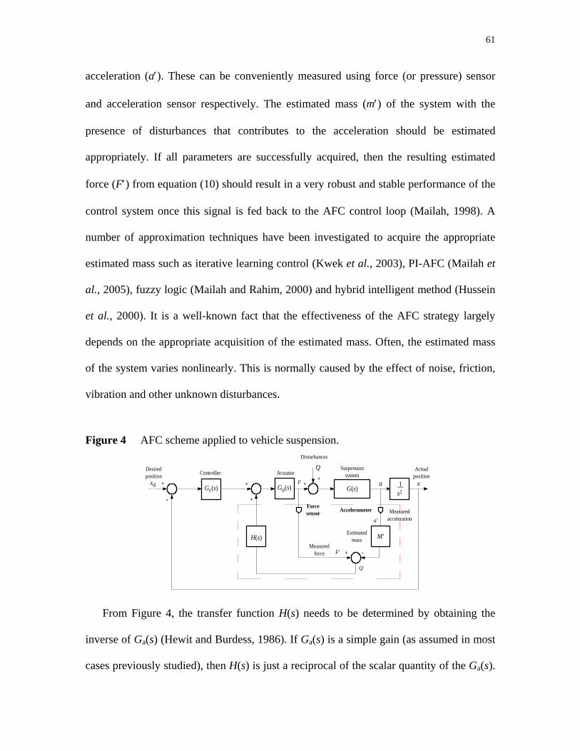
61
acceleration (a′). These can be conveniently measured using force (or pressure) sensor
and acceleration sensor respectively. The estimated mass (m′) of the system with the
presence of disturbances that contributes to the acceleration should be estimated
appropriately. If all parameters are successfully acquired, then the resulting estimated
force (F′) from equation (10) should result in a very robust and stable performance of the
control system once this signal is fed back to the AFC control loop (Mailah, 1998). A
number of approximation techniques have been investigated to acquire the appropriate
estimated mass such as iterative learning control (Kwek et al., 2003), PI-AFC (Mailah et
al., 2005), fuzzy logic (Mailah and Rahim, 2000) and hybrid intelligent method (Hussein
et al., 2000). It is a well-known fact that the effectiveness of the AFC strategy largely
depends on the appropriate acquisition of the estimated mass. Often, the estimated mass
of the system varies nonlinearly. This is normally caused by the effect of noise, friction,
vibration and other unknown disturbances.
Figure 4 AFC scheme applied to vehicle suspension.
Ga(s) G(s)
M'H(s)
Q+F
Forcesensor Accelerometer
+ -
Q'
+
+
aGc(s) 1 s2
+
-
xd x+
F'
Disturbances
Suspension systemActuatorController
Desiredposition
Actualposition
Estimatedmass
Measured force
Measuredaccelerationa'
From Figure 4, the transfer function H(s) needs to be determined by obtaining the
inverse of Ga(s) (Hewit and Burdess, 1986). If Ga(s) is a simple gain (as assumed in most
cases previously studied), then H(s) is just a reciprocal of the scalar quantity of the Ga(s).
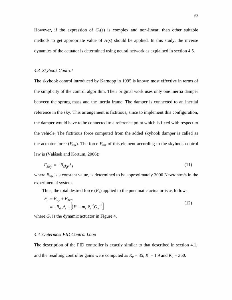
62
However, if the expression of Ga(s) is complex and non-linear, then other suitable
methods to get appropriate value of H(s) should be applied. In this study, the inverse
dynamics of the actuator is determined using neural network as explained in section 4.5.
4.3 Skyhook Control
The skyhook control introduced by Karnopp in 1995 is known most effective in terms of
the simplicity of the control algorithm. Their original work uses only one inertia damper
between the sprung mass and the inertia frame. The damper is connected to an inertial
reference in the sky. This arrangement is fictitious, since to implement this configuration,
the damper would have to be connected to a reference point which is fixed with respect to
the vehicle. The fictitious force computed from the added skyhook damper is called as
the actuator force (Fsky). The force Fsky of this element according to the skyhook control
law is (Valásek and Kortüm, 2006):
szskyBskyF &−= (11)
where Bsky is a constant value, is determined to be approximately 3000 Newton/m/s in the
experimental system.
Thus, the total desired force (Fd) applied to the pneumatic actuator is as follows:
( )[ ]1−′′−′+−=
+=
assssky
AFCskyd
GzmFzB
FFF
&&& (12)
where Ga is the dynamic actuator in Figure 4.
4.4 Outermost PID Control Loop
The description of the PID controller is exactly similar to that described in section 4.1,
and the resulting controller gains were computed as Kp = 35, Ki = 1.9 and Kd = 360.

63
4.5 Implementation of Neural Network
NN has potentials to be applied for intelligent control system because it can learn, adapt,
and approximate nonlinear functions very well. The feed-forward NN structure in this
work employed a one hidden layer network with three hidden neurons network that
resembles the one described in Wilamowski et al. (1999). Sigmoid bipolar is chosen for
hidden layer and linear function for output layer. All parameters of the model were
normalized in the range of [-1,1] representing the minimum and maximum range of the
parameter values.
Error between the outputs of the plant and network is used as the learning signal for
NN to get appropriate weights and biases. The learning algorithm which is based on
minimizing the error (mean square error) can be given as follows:
))()(())()(()(2 kykykykyke adT
ad −−= (13)
where e is current error, yd is desired output, ya is current output at iteration-k.
There are a number of learning algorithms reported in the literature; the two most
frequently used are the error backpropagation (BP) and Levenberg-Marquardt (LM)
algorithms. The LM algorithm is currently considered as the more efficient second order
algorithm for training the feedforward NN (Wilamowski et al., 2001).
To minimize error with respect to the weights, updating the weights of each layer
using LM method in time t > 0 can be represented as follows (Hagan and Menhaj, 1994):
)()()1( kwkwkw ijijij ∆+=+ (14)
[ ] ))(())(())(())(()(1
kwekwJIkwJkwJkw ijijijijT
ij−
+=∆ µ (15)
where wi,j is weight, J is Jacobian matrix, µ is learning rate and I is identity matrix.
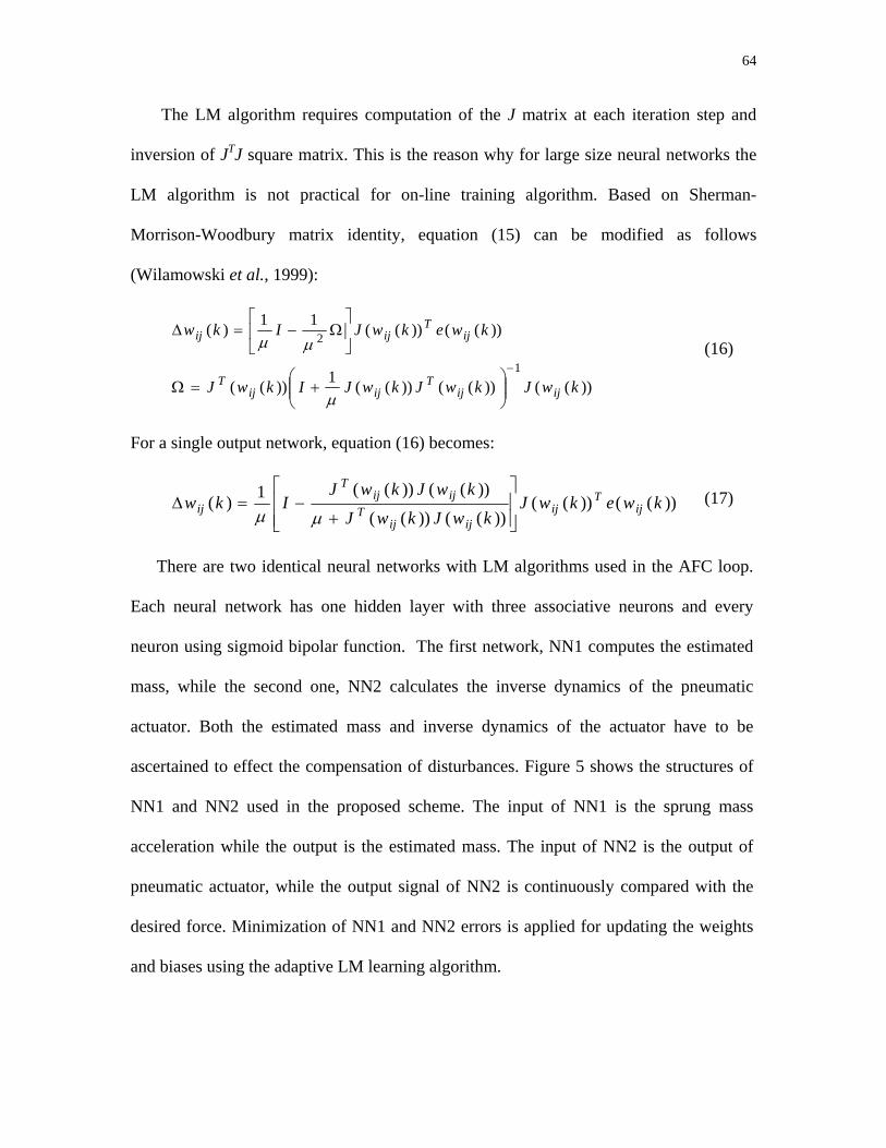
64
The LM algorithm requires computation of the J matrix at each iteration step and
inversion of JTJ square matrix. This is the reason why for large size neural networks the
LM algorithm is not practical for on-line training algorithm. Based on Sherman-
Morrison-Woodbury matrix identity, equation (15) can be modified as follows
(Wilamowski et al., 1999):
))(())(())((1))((
))(())((11)(
1
2
kwJkwJkwJIkwJ
kwekwJIkw
ijijT
ijijT
ijT
ijij
−
⎟⎟⎠
⎞⎜⎜⎝
⎛+=Ω
⎥⎦
⎤⎢⎣
⎡Ω−=∆
µ
µµ (16)
For a single output network, equation (16) becomes:
))(())(())(())((
))(())((1)( kwekwJkwJkwJ
kwJkwJIkw ij
Tij
ijijT
ijijT
ij⎥⎥⎦
⎤
⎢⎢⎣
⎡
+−=∆µµ
(17)
There are two identical neural networks with LM algorithms used in the AFC loop.
Each neural network has one hidden layer with three associative neurons and every
neuron using sigmoid bipolar function. The first network, NN1 computes the estimated
mass, while the second one, NN2 calculates the inverse dynamics of the pneumatic
actuator. Both the estimated mass and inverse dynamics of the actuator have to be
ascertained to effect the compensation of disturbances. Figure 5 shows the structures of
NN1 and NN2 used in the proposed scheme. The input of NN1 is the sprung mass
acceleration while the output is the estimated mass. The input of NN2 is the output of
pneumatic actuator, while the output signal of NN2 is continuously compared with the
desired force. Minimization of NN1 and NN2 errors is applied for updating the weights
and biases using the adaptive LM learning algorithm.
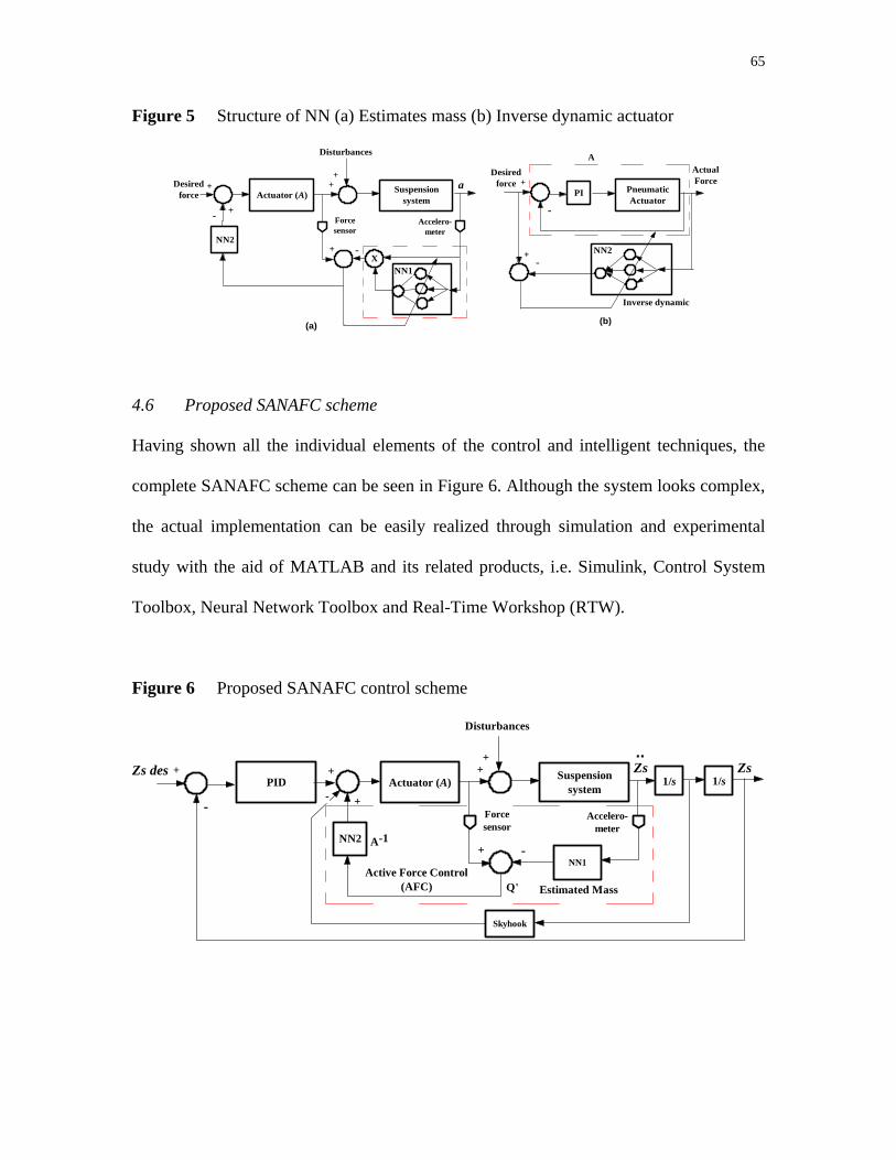
65
Figure 5 Structure of NN (a) Estimates mass (b) Inverse dynamic actuator
PneumaticActuator
PI+
-
+-
Desiredforce
ActualForce
NN2
Actuator (A)
NN2
Suspensionsystem
+
- +
++
+ -
Forcesensor
Accelero-meter
Disturbances
Desiredforce
a
XNN1
(a) (b)
A
Inverse dynamic
4.6 Proposed SANAFC scheme
Having shown all the individual elements of the control and intelligent techniques, the
complete SANAFC scheme can be seen in Figure 6. Although the system looks complex,
the actual implementation can be easily realized through simulation and experimental
study with the aid of MATLAB and its related products, i.e. Simulink, Control System
Toolbox, Neural Network Toolbox and Real-Time Workshop (RTW).
Figure 6 Proposed SANAFC control scheme
Actuator (A)
NN2
Suspensionsystem
NN1
1/s 1/s+
- +
++
+ -
Forcesensor
Accelero-meter
Disturbances
Zs
Q'
PIDZs des +
Active Force Control (AFC)
Zs..
Estimated Mass
A-1
Skyhook
-
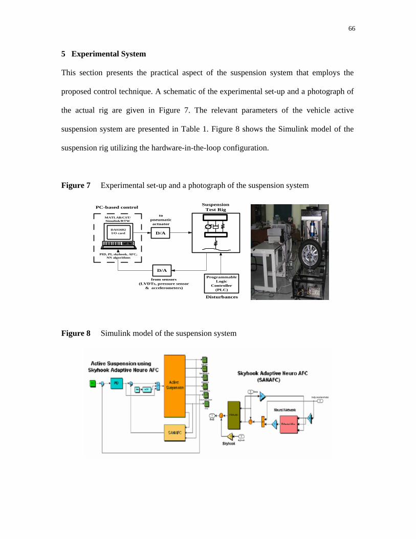
66
5 Experimental System
This section presents the practical aspect of the suspension system that employs the
proposed control technique. A schematic of the experimental set-up and a photograph of
the actual rig are given in Figure 7. The relevant parameters of the vehicle active
suspension system are presented in Table 1. Figure 8 shows the Simulink model of the
suspension rig utilizing the hardware-in-the-loop configuration.
Figure 7 Experimental set-up and a photograph of the suspension system
D/A
D/A
Suspension Test RigPC-based control
MATLAB/CST/Simulink/RTW
DAS1602I/O card
to pneumatic actuator
from sensors (LVDTs, pressure sensor
& accelerometers)
PID, PI, skyhook, AFC, NN algorithms
Programmable Logic
Controller (PLC)
Disturbances
Figure 8 Simulink model of the suspension system

67
Table 1 Vehicle suspension and pneumatic parameters
Description Value Description Value
sprung mass (kg)
unsprung mass (kg)
suspension damping (N/m/sec)
suspension stiffness (N/m)
170
25
1130
10520
tyre stiffness (N/m)
stroke length (mm)
diameter bore (mm)
ram area (mm2)
86240
116
40
0.0076
Physical sensors required for input/output (I/O) signals were connected to a PC-based
data acquisition and control system using MATLAB, Simulink and Real-Time Workshop
(RTW) that essentially constitute a hardware-in-the-loop configuration, implying that the
simulation can be effectively converted to the equivalent practical scheme without much
fuss. A 100 Hz sampling frequency was used in conjunction with a data acquisition card
(Keithley Metrabyte DAS 1602) that is fitted into one of the expansion slots of the PC.
Appropriate signals are processed using the analogue-to-digital (A/D) and digital-to-
analogue converters (D/A) channels which are already embedded in the DAS card.
Accelerometers were installed at the sprung and unsprung masses of the vehicle
suspension to measure body acceleration and tyre deflection, respectively. A linear
variable differential transformer (LVDT) was placed in between the sprung and unsprung
masses to the measure suspension deflection. Another LVDT was used to measure the
vertical displacement of road profile. Two types of road profiles (as disturbances) were
used in the form of approximate sinusoidal signals generated by a specially designed
pneumatic system controlled by a programmable logic controller (PLC). The generated
signals are depicted in Figure 9. The pneumatic actuator is connected with a proportional
pneumatic valve, Koganei ETR600-2.
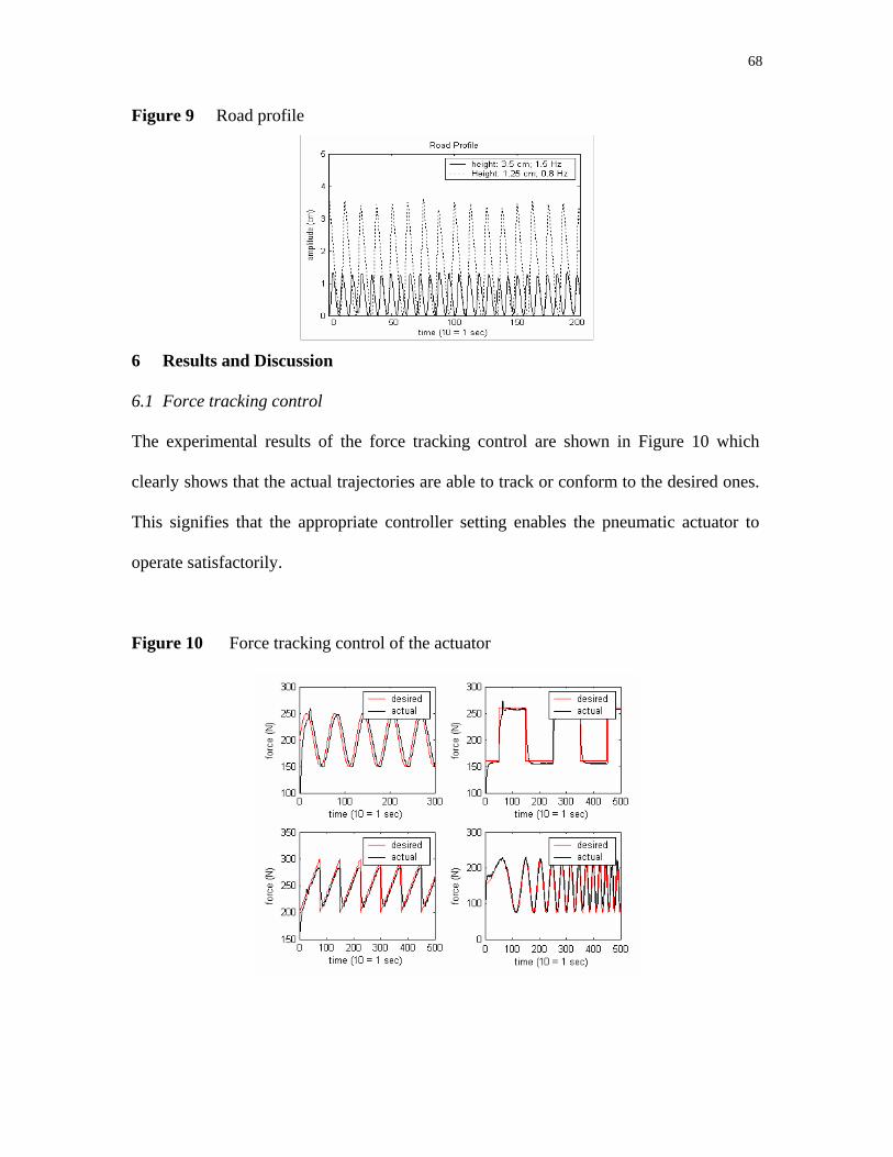
68
Figure 9 Road profile
6 Results and Discussion
6.1 Force tracking control
The experimental results of the force tracking control are shown in Figure 10 which
clearly shows that the actual trajectories are able to track or conform to the desired ones.
This signifies that the appropriate controller setting enables the pneumatic actuator to
operate satisfactorily.
Figure 10 Force tracking control of the actuator
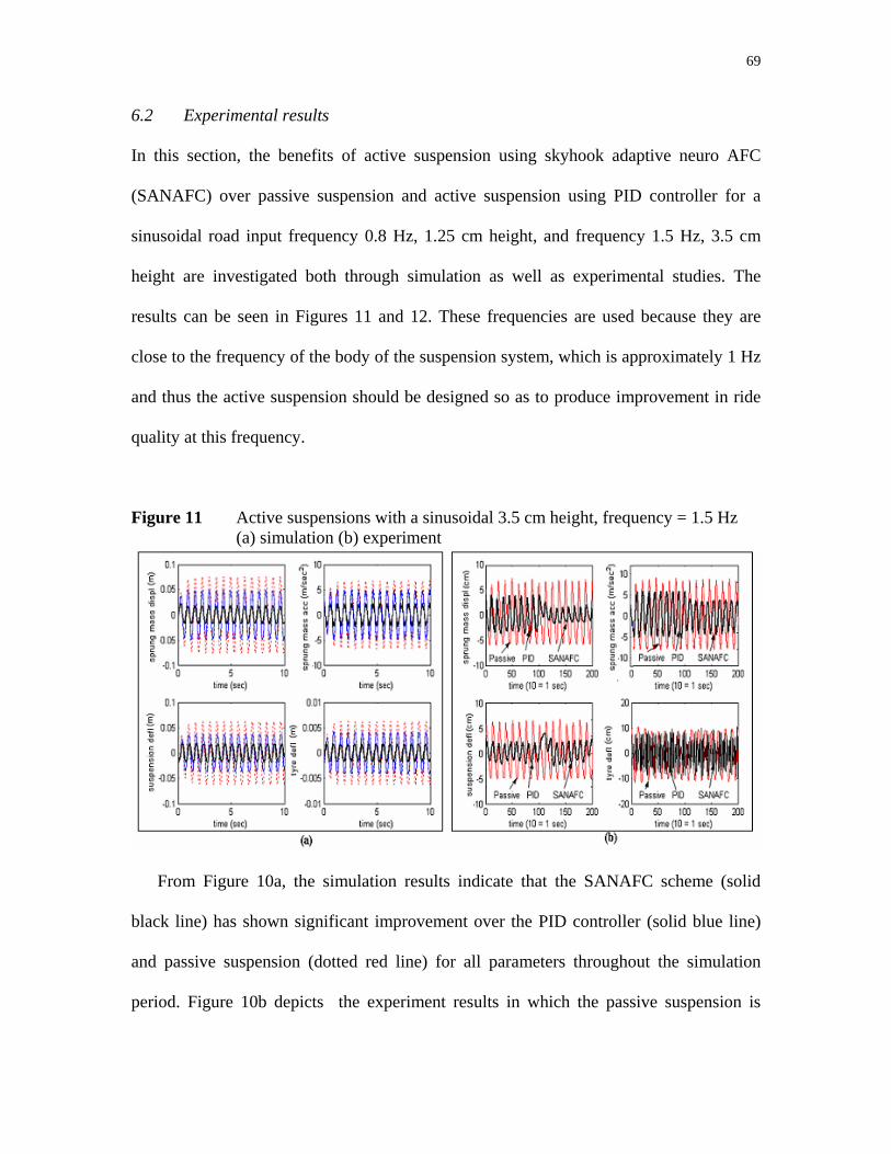
69
6.2 Experimental results
In this section, the benefits of active suspension using skyhook adaptive neuro AFC
(SANAFC) over passive suspension and active suspension using PID controller for a
sinusoidal road input frequency 0.8 Hz, 1.25 cm height, and frequency 1.5 Hz, 3.5 cm
height are investigated both through simulation as well as experimental studies. The
results can be seen in Figures 11 and 12. These frequencies are used because they are
close to the frequency of the body of the suspension system, which is approximately 1 Hz
and thus the active suspension should be designed so as to produce improvement in ride
quality at this frequency.
Figure 11 Active suspensions with a sinusoidal 3.5 cm height, frequency = 1.5 Hz (a) simulation (b) experiment
From Figure 10a, the simulation results indicate that the SANAFC scheme (solid
black line) has shown significant improvement over the PID controller (solid blue line)
and passive suspension (dotted red line) for all parameters throughout the simulation
period. Figure 10b depicts the experiment results in which the passive suspension is
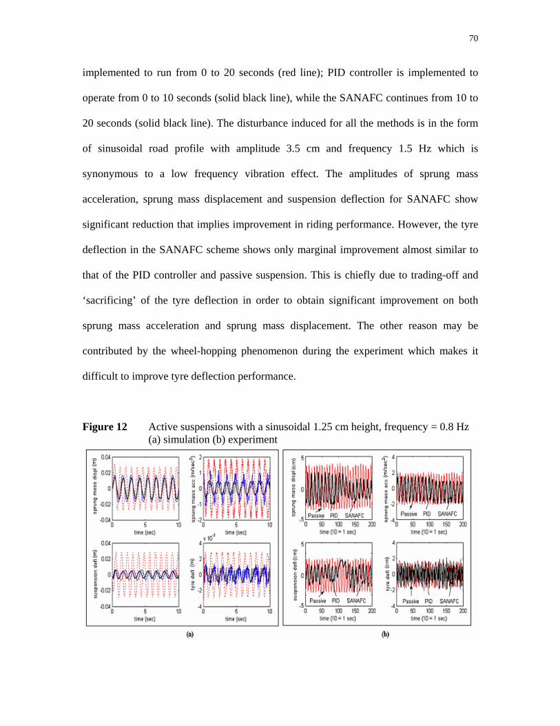
70
implemented to run from 0 to 20 seconds (red line); PID controller is implemented to
operate from 0 to 10 seconds (solid black line), while the SANAFC continues from 10 to
20 seconds (solid black line). The disturbance induced for all the methods is in the form
of sinusoidal road profile with amplitude 3.5 cm and frequency 1.5 Hz which is
synonymous to a low frequency vibration effect. The amplitudes of sprung mass
acceleration, sprung mass displacement and suspension deflection for SANAFC show
significant reduction that implies improvement in riding performance. However, the tyre
deflection in the SANAFC scheme shows only marginal improvement almost similar to
that of the PID controller and passive suspension. This is chiefly due to trading-off and
‘sacrificing’ of the tyre deflection in order to obtain significant improvement on both
sprung mass acceleration and sprung mass displacement. The other reason may be
contributed by the wheel-hopping phenomenon during the experiment which makes it
difficult to improve tyre deflection performance.
Figure 12 Active suspensions with a sinusoidal 1.25 cm height, frequency = 0.8 Hz (a) simulation (b) experiment

71
From Figures 12a and 12b, the amplitudes of sprung mass acceleration, sprung mass
displacement and suspension deflection for active suspension based on SANAFC still
show improvement compared to both PID controller and passive suspension, although
these amplitudes are smaller than those in Figure 11. Again, for the experimental part, the
amplitude of the tyre deflection for the SANAFC scheme shows almost indifferent results
with the PID controller and passive suspension counterparts.
8 Conclusion
A novel controller employing the skyhook adaptive neuro active force control
(SANAFC) has been designed and implemented for the control of a vehicle quarter car
active suspension. The simulation of the scheme readily produces results which illustrate
the superiority of the scheme over its counterparts in all aspects related to its riding
performance. From the experimental results, it can be also deduced that the active
suspension based on SANAFC controller outperforms the PID controller and passive
suspension in all selected performance criteria. Thus, it can be concluded that the
SANAFC controller is very effective in isolating the vibration effect on the sprung mass
which in turn considerably improve the overall system performance. Future works may
include more effort in improving the tyre deflection performance and consider other
operating and loading conditions.
Acknowledgements
The authors would like to thank the Malaysian Ministry of Science and Technology and Innovation (MOSTI) and Universiti Teknologi Malaysia (UTM) for their continuous support in the research work. This research was fully supported by an IRPA grant (No. 03-02-06-0123EA001).
72
References Alleyne, A. and Hedrick, J.K. (1995) 'Nonlinear adaptive control of active suspension', IEEE Trans. on
Control System Technology, vol. 3(1): 94-101.
Astrom, K.J. and Hagglund, T. (1984) ‘Automatic tuning of simple regulators with specification on phase and amplitude margin’, Automatica, vol. 20, 645–651.
Chantranuwathana, S. and Peng, H. (1999) ‘Force tracking control for active suspensions - theory and experiments’, Proceedings of the IEEE International Conference on Control Applications, 22-27 August, Hawaii, USA, vol. 1: 442–447.
D’Amato, F.J. and Viassolo, D.E. (2000) ‘Fuzzy Control for Active Suspensions’, Mechatronics, vol. 10: 897-920.
Fu, L.J., Cao, J.G., Liao, C.R. and Chen, B. (2005) ‘Study on Neural Networks Control Algorithms for Automotive Adaptive Suspension Systems’, International Conference on Neural Networks and Brain 2005, vol. 3: 1795-1799.
Gross, D.C. and Rattan, K.S. (1998) 'An adaptive multilayer neural network for trajectory tracking control of a pneumatic cylinder’, IEEE International Conference on Systems, Man, and Cybernetics 1998, 11-14 October, vol. 2: 1662 – 1667.
Hagan, M.T. and Menhaj, M.B. (1994) ‘Training feedforward networks with the Marquardt algorithm’, IEEE Transactions on Neural Network, vol. 5(6): 989-993.
Hamiti, K., Voda-Besanqon, A. and Roux-Buisson, H. (1996) ‘Position control of a pneumatic actuator under the influence of stiction’, Control Engineering Practice, vol. 4(8): 1079-1088.
Hewit, J.R. and Burdess, J.R. (1986) ‘An active method for the control of mechanical systems in the presence of unmeasurable forcing’, Trans. Mechanism and machine Theory, 21(3): 393-400.
Hewit, J.R. and Marouf, K.B. (1996) ‘Practical control enhancement via mechatronics design’, IEEE Transactions on Industrial Electronics, vol. 43(1): 16-22.
Huang, S.J. and Lin, W.C. (2003) ‘A self organizing fuzzy controller for an active suspension system’, Journal of Vibration and Control, vol. 9(9): 1023-1040.
Hussein, S.B., Jamaluddin, H., Mailah M. and Zalzala, A. (2000) ‘A hybrid intelligent active force controller for robot arm using evolutionary neural networks’, Proc. Int. Conf. on Evolutionary Computation (CEC 2000), San Diego, USA, 117-124.
Ikenaga, S.A., Lewis, F.L., Davis, L., Kampos, J., Evans, M. and Scully, S. (1999) ‘Active suspension control using a novel strut and active filtered feedback: design and implementation’, Proc. of IEEE International Conference on Control Applications, Hawaii, USA: 1502-1508.
Ikenaga, S.A. (2000) ‘Development of a real time digital controller: application to active suspension control of ground vehicle’, University of Texas at Arlington, Ph.D. Thesis.
Kwek, L.C., Wong, E.K., Loo, C.K. and Rao, M.V.C. (2003) ‘Application of Active Force Control and Iterative Learning in a 5-Link Biped Robot’, Journal of Intelligent and Robotic Systems, vol. 37: 143–162.
Lin, J.S. and Kenellakopoulos, I. (1997) ‘Nonlinear design of active suspensions’, Control Systems Magazine, vol. 17(3): 45-59.
Mailah, M. (1998) ‘Intelligent active force control of a rigid robot arm using neural network and iterative learning algorithms’, University of Dundee, Ph.D. Thesis.
Mailah, M. and Rahim, N.I.A. (2000) ‘Intelligent active force control of a robot arm using fuzzy logic’, IEEE Int. Conf. on Intelligent Systems and Technologies TENCON 2000, Kuala Lumpur, 291-296.
Mailah, M., Pitowarno, E. and Jamaluddin, H. (2005) ‘Robust motion control for mobile manipulator using resolved acceleration and proportional-integral active force control’, International Journal of Advanced Robotic Systems, vol. 2(2): 125-134.

73
Miller, L.R. (1988) ‘Tuning passive, semi active, and fully active suspension’, Proceedings of the 27th Conference on Decision and Control, Austin, Texas, 7-9 December, vol. 3: 2047-2053.
Richer, E. and Hurmuzlu, Y. (2000) ‘A High Performance Pneumatic Force Actuator System: Part I - Nonlinear Mathematical Model’, Transactions of the ASME, vol. 122: 416-425.
Valásek, M. and Kortüm, W. (2006) ‘Mechanical Systems Design Handbook: Modeling, Measurement, and Control’, Taylor and Francis Group, LLC.
Wilamowski, B.M., Chen, Y. and Malinowski, A. (1999) ‘Efficient algorithm for training neural networks with one hidden layer’, Proceedings of International Joint Conference on Neural Networks, vol. 3: 1725-1728.
Wilamowski, B.M., Iplikci, S., Kaynak, O. and Efe, M.O. (2001) ‘An Algorithm for Fast Convergence in Training Neural Networks’, Proceedings International Joint Conference on Neural Networks, vol. 3: 1778-1782.
Yoshimura, T., Kume, A., Kurimoto, M. and Hino, J. (2001) ‘Construction of an active suspension system of a quarter car model using the concept of sliding mode control’, Journal of Sound and Vibration, 239(2): 187-199.
Yoshimura T. and Takagi A. (2004) ‘Pneumatic active suspension system for a one-wheel car model using fuzzy reasoning and a disturbance observer’, Journal of Zhejiang University SCIENCE, vol. 5(9): 1060-1068.

CHAPTER 7
VEHICLE ACTIVE SUSPENSION SYSTEM USING SKYHOOK ADAPTIVE NEURO ACTIVE FORCE CONTROL
Gigih Priyandoko, Musa Mailah & Hishamuddin Jamaluddin
To be submitted to Mechatronics (an International Journal), May 2007

CHAPTER 8
CONCLUSIONS AND RECOMMENDATIONS
8.1 Conclusions
Specific objectives of the project have been met. A very robust active
suspension system using intelligent active force control (AFC) strategy has been
designed and developed both through simulation and experimental studies. The
performance of the proposed system has been tested and evaluated based on
numerous loading and operating conditions.
The simulation work suggests that the riding comfort of the active suspension
system with AFC-based scheme is considerably improved through the suppression of
the body acceleration and displacement in the event of different road profiles and
vibration excitation. Both the linear and non-linear modelled actuators incorporated
into the schemes as the main active elements of the proposed system were effective
in generating the necessary torques to cancel out the disturbances in the AFC loop.
Intelligent methods to compute the estimated virtual mass using neural network
(NN), adaptive fuzzy logic (AFL) and their hybrid seems to indicate that the
estimated parameter has been appropriately identified and used. The results clearly
show the robust performance of the systems that almost render the body (sprung
mass) of the quarter car model unaffected by the changes in the applied external
forces and variation in parameters. This demonstrates the improved riding comfort of
the vehicle having the abovesaid control elements.
75
The practical system was successfully realized in the form of a working
prototype active suspension system employing a number of control schemes that are
theoretically defined in the report. The AFC schemes were designed and
implemented into the prototype by way of rigorous programming, interfacing and
control taking into account the hardware-in-the-loop configuration using MATLAB,
Simulink and Real-Time Workshop (RTW) with various inputs (sensory devices)
and outputs (actuators). The results obtained from the experiments do complement
and ‘tally’ with those of the theoretical (simulation) counterparts implying that the
schemes were successfully validated even though it was found that the experimental
findings were rather crude and much lower in accuracy, obviously due to a number
of physical constraints. Indeed, a complete mechatronic approach and design was
fully exploited in the research.
8.2 Recommendations for Future Works
A number of recommendations for future works is listed as follows:
• Perform a rigorous stability analysis of the suspension system with
various AFC-based schemes.
• Simulate system using other forms of operating and loading conditions to
further investigate the system robustness and accuracy in performing its
tasks. This may include different road profiles, excitations, payloads and
other forms of external disturbances and considering responses at higher
frequencies.
• Add more intelligence to the system be it through software program
(incorporating other articicial intelligence (AI) techniques) or hardware
by way of using intelligent (or smart) sensors and electronics.
• Solve some of the current problems related to physical hardware
constraints such as appropriate mounting of sensors and actuators and
also using more accurate sensors.

76
• Further practical experiments need to be carried out to obtain other useful
characteristics or behaviours of the active suspension.
• The suspension system can be further tested taking into account half-car
or full-car models.
• A fast active hydraulic actuator system can be considered in place of the
penumatic counterpart.
77
REFERENCES
Alleyne, A. and Hedrick, J.K. (1995). Nonlinear adaptive control of active suspension,
IEEE Trans. on Control System Technology, vol. 3(1): 94-101.
Alleyne, A.; Liu, R.; Wright, H. (1998). On the limitations of force tracking control for
hydraulic active suspensions, Proceedings of the American Control Conference,
Volume 1, 24-26 June, 43 – 47.
Appleyard, M.; Wellstead, P.E. (1995). Active suspension: some background, IEE
Proceedings of Control Theory Application, vol. 142, no. 2, 123-128
Astrom, K.J. and Hagglund, T. (1984). Automatic tuning of simple regulators with
specification on phase and amplitude margin, Automatica, vol. 20, 645–651.
Babuška, R. (2002). Neuro-fuzzy methods for modelling and identification, Abraham, A.;
Jain, L.C.; Kacprzyk, J. (Editors), Recent Advances in Intelligent Paradigms and
Applications, Springer-Verlag, Heidelberg, 161–186.
Baladi, P. Hornik K. (1989). Neural networks and principal component analysis: learning
from examples and local minima, Neural Networks, 2, 53-58.
Barr, A.J.; Ray, J.I (1996). Control of an active suspension using fuzzy logic,
Proceedings of the Fifth IEEE International Conference on Fuzzy Systems, Vol.
1, Pages:42 - 48 vol.1, 8-11.
Billings, S.A., Jamaluddin, H.B., Chen, S. (1992). Properties of neural network with
applications to modelling non-linear dynamic systems, Int. Journal of Control, vol.
55, no. 1, 193-224.
Buckner, G.D., Schuetze, K.T., Beno, J.H. (2000). Active Vehicle Suspension Control
Using Intelligent Feedback Linearization, Proc. of the American Control
Conference, Chicago, Illinois.
78
Campos, J., Lewis, F.L., Davis, L., Ikenaga, S. (2000). Backstepping Based Fuzzy
Control of Active Vehicle Suspension Systems, American Control Conference,
2000. Proceedings of the 2000, Volume: 6, 28-30.
Chantranuwathana, S. and Peng, H. (1999). Force tracking control for active suspensions
- theory and experiments, Proceedings of the IEEE International Conference on
Control Applications, 22-27 August, Hawaii, USA, vol. 1: 442–447.
Chantranuwathana, S.; Peng, H. (2004). Adaptive Robust Force Control for Vehicle
Active Suspensions, International Journal of Adaptive Control and Signal
Processing, 2004, 18:83-102.
Chen, H.Y.; Huang, H.J. (2005). Adaptive sliding controller for active suspension
system, International Conference on Control and Automation, Volume 1, 26-29
June, 282 – 287.
Cherry, A.S.; Jones, R.P. (1995). Fuzzy logic control of an automotive suspension
system, IEE Proceedings of Control Theory Application, vol. 142, no. 2, 149-160
D’Amato, F.J.; Viassolo, D.E. (2000). Fuzzy control for active suspensions,
Mechatronics, Vol.10, 897-920.
Fu, L.J., Cao, J.G., Liao, C.R. and Chen, B. (2005) ‘Study on Neural Networks Control
Algorithms for Automotive Adaptive Suspension Systems’, International
Conference on Neural Networks and Brain 2005, vol. 3: 1795-1799.
Gross, D.C. and Rattan, K.S. (1998). An adaptive multilayer neural network for trajectory
tracking control of a pneumatic cylinder, IEEE International Conference on
Systems, Man, and Cybernetics 1998, 11-14 October, vol. 2: 1662 – 1667.
Guo, Q.J., Yu, H.B., Xu, A.D. (2006). A hybrid PSO-GD based intelligent method for
machine diagnosis, Digital Signal Processing, vol. 5, p. 1-17.
Hagan, M.T. and Menhaj, M.B. (1994). Training feedforward networks with the
Marquardt algorithm, IEEE Transactions on Neural Network, vol. 5(6): 989-993.
Hamiti, K., Voda-Besanqon, A. and Roux-Buisson, H. (1996). Position control of a
pneumatic actuator under the influence of stiction, Control Engineering Practice,
vol. 4(8): 1079-1088.
79
Hewit, J.R. and Burdess, J.R. (1986). An active method for the control of mechanical
systems in the presence of unmeasurable forcing, Trans. Mechanism and machine
Theory, 21(3): 393-400.
Hewit, J.R. and Marouf, K.B. (1996). Practical control enhancement via mechatronics
design, IEEE Transactions on Industrial Electronics, vol. 43(1): 16-22.
Hewit, J.R.; Moris, J.R. (1999). Disturbance observer control with estimation of the
inertia matrix, Proceedings of IEEE/ASME International Conference on Advanced
Intelligent Mechatronics, 753-757.
Huang, S.J. and Lin, W.C. (2003). A self organizing fuzzy controller for an active
suspension system, Journal of Vibration and Control, vol. 9(9): 1023-1040.
Hudha, K., Jamaluddin, H., Samin, P.M., Rahman, R.A. (2003). Active Roll Control
Suspension System (ARCS) Using Active Force Control Strategy on A New
Modified Half Car Model. Procs. of SAE.
Hussein, S.B., Jamaluddin, H., Mailah M. and Zalzala, A. (2000). A hybrid intelligent
active force controller for robot arm using evolutionary neural networks, Proc. Int.
Conf. on Evolutionary Computation (CEC 2000), San Diego, USA, 117-124.
Hussein, S.B., Zalzala, A.M.S.; Jamaluddin, H.; Mailah, M. (2000). An evolutionary
neural network controller for intelligent active force control, Evolutionary Design
and Manufacture, Parmee, I.C. (Editor), Springer Verlag, London, 352-362.
Ikenaga, S.A. (2000). Development of a real time digital controller: application to active
suspension control of ground vehicle, University of Texas at Arlington, Ph.D.
Thesis.
Ikenaga, S.A., Lewis, F.L., Davis, L., Kampos, J., Evans, M. and Scully, S. (1999).
Active suspension control using a novel strut and active filtered feedback: design
and implementation, Proc. of IEEE International Conference on Control
Applications, Hawaii, USA: 1502-1508.
Jha, R., Rower, J. (2002). Experimental investigation of active vibration control using
neural networks and piezoelectric actuators, Smart Materials and Structures, 11,
115–121.
80
Joo, D.S.; Al-Holou, N.; Weaver, J.M.; Lahdhiri, T.; Al-Abbas, F. (2000). Nonlinear
modeling of vehicle suspension system, Proceedings of the American Control
Conference, Volume 1, Issue 6, 28-30 June, 115 -119.
Joo, Dae-Sung, Al-Holou, N., Weaver, J.M., Lahdhiri, T., Al-Abbas, F. (2000).
Nonlinear modelling of vehicle suspension system, Proc. of the 2000 American
Control Conference, Vol. 1, Issue 6, 28-30.
Kennedy, J., Eberhart, R.C. (1995). Particle Swarm Optimisation, Proc. IEEE
International Conference on Neural Networks, IV, 1942-1948.
Kwek, L.C., Wong, E.K., Loo, C.K. and Rao, M.V.C. (2003). Application of Active
Force Control and Iterative Learning in a 5-Link Biped Robot, Journal of Intelligent
and Robotic Systems, vol. 37: 143–162.
Lin, J.S. and Kenellakopoulos, I. (1997). Nonlinear design of active suspensions, Control
Systems Magazine, vol. 17(3): 45-59.
Lu, W.Z., Fan, H.Y., Leung, A.Y. T., Wong, J.C.K. (2002). Analysis of pollutant levels
in central Hong Kong applying neural network method with particle swarm
optimization, Environmental Monitoring and Assessment, 79, 217–230.
Mailah, M. (1998). Intelligent Active Force Control of A Rigid Robot Arm Using Neural
Network and Iterative Learning Algorithms, Ph.D Thesis, University of Dundee,
UK.
Mailah, M., Pitowarno, E. and Jamaluddin, H. (2005). Robust motion control for mobile
manipulator using resolved acceleration and proportional-integral active force
control, International Journal of Advanced Robotic Systems, vol. 2(2): 125-134.
Mailah, M., Rahim, N.I.A. (2000). Intelligent active force control of a robot arm using
fuzzy logic, Proceedings of IEEE International Conference on Intelligent Systems
and Technologies TENCON 2000, 291-296.
Miller, L.R. (1988) ‘Tuning passive, semi active, and fully active suspension’,
Proceedings of the 27th Conference on Decision and Control, Austin, Texas, 7-9
December, vol. 3: 2047-2053.
Mock, J. R.; Weeks, D. A.; Beno, J. H.; Nichols, S. P.; Bresie D. A.; Guenin, A. M.
(2002). Dual Purpose Fuzzy Logic Controller for an Active Suspension System,
SAE 2002 World Congress, Detroit, Michigan, March 4-7, 2002.

81
Narendra, K.S. (1996). Neural networks for control: theory and practice, Proc. IEEE 84,
1385–406.
Negnevitsky, M. (2005). Artificial Intelligence: A Guide to Intelligent Systems, 2nd,
Addison Wesley.
Nguyen, T.T.; Bui, T.H.; Tran, T.P.; Kim, S.B. (2001). A hybrid control of active
suspension system using H∞ and nonlinear adaptive controls, Proceedings of ISEI
2001, Volume 2, 12-16 June 2001, 839 – 844.
Omar, Z. (2002). Modelling and Simulation of an Active Suspension System Using
Active Force Control Strategy, MSc Report, Universiti Teknologi Malaysia.
Parsopoulos, K.E., Vrahatis, M.N. (2002). Recent approaches to global optimization
problems through Particle Swarm Optimization, Natural Computing, 1, 235–306.
Rao, M.V.C., Prahlad, V. (1997). A Tunable Fuzzy Logic Controller for Vehicle Active
Suspension Systems, Fuzzy Set and System.
Richer, E. and Hurmuzlu, Y. (2000). A High Performance Pneumatic Force Actuator
System: Part I - Nonlinear Mathematical Model, Transactions of the ASME, vol.
122: 416-425.
Sam, Y.M. (2004). Modelling and Control of Hydraulically Actuated Active Suspension
Systems, PhD Thesis, Universiti Teknologi Malaysia.
Sun, J.; Yang, Q. (2005). Self-adjustment fuzzy control of automobile active suspension,
Proceedings IEEE Intelligent Vehicles Symposium, 6-8 June 2005, 354 – 357.
Taghirad, H.D.; Esmailzadeh, E. (1998). Automobile passenger comfort assured through
LQG/LQR active suspension, Journal of Vibration and Control, Incorporating
Modal Analysis, 4(5), 603 – 618.
Valásek, M. and Kortüm, W. (2006). Mechanical Systems Design Handbook: Modeling,
Measurement, and Control, Taylor and Francis Group, LLC.
Van den Bergh, F. (1999). Particle Swarm weight initialization in multi-layer perceptron
artificial neural networks, ICAI, Durban, South Africa.
Wang, L-X. (1994). Adaptive Fuzzy Systems and Control, Prentice Hall, Englewood
Cliffs, NJ.
Wilamowski, B.M. (2003). Neural network architectures and learning, IEEE
International Conference on Industrial Technology, Vol. 1, 10-12.
82
Wilamowski, B.M., Chen, Y. and Malinowski, A. (1999). Efficient algorithm for training
neural networks with one hidden layer, Proceedings of International Joint
Conference on Neural Networks, vol. 3: 1725-1728.
Wilamowski, B.M., Iplikci, S., Kaynak, O. and Efe, M.O. (2001). An Algorithm for Fast
Convergence in Training Neural Networks, Proceedings International Joint
Conference on Neural Networks, vol. 3: 1778-1782.
Yim, Y.U, Oh, S.Y. (2004). Modelling of Vehicle Dynamics From Real Vehicle
Measurements Using a Neural Network With Two-Stage Hybrid Learning for
Accurate Long-Term Prediction, IEEE Trans. on Vehicular Technology, Vol. 53,
No. 4.
Yoshimura T. and Takagi A. (2004). Pneumatic active suspension system for a one-wheel
car model using fuzzy reasoning and a disturbance observer, Journal of Zhejiang
University SCIENCE, vol. 5(9): 1060-1068.
Yoshimura, T., Kume, A., Kurimoto, M. and Hino, J. (2001). Construction of an active
suspension system of a quarter car model using the concept of sliding mode control,
Journal of Sound and Vibration, 239(2): 187-199.

xix
LIST OF APPENDICES
APPENDIX TITLE PAGE
A Results 83
B Photographs of Rig 92
C List of Publications 96
D Achievements / Outputs 98
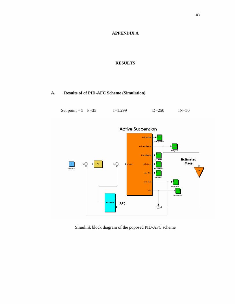
83
APPENDIX A
RESULTS
A. Results of of PID-AFC Scheme (Simulation)
Set point = 5 P=35 I=1.299 D=250 IN=50
Simulink block diagram of the poposed PID-AFC scheme

84
Suspension deflection without disturbance
Graph of amplitude versus iteration
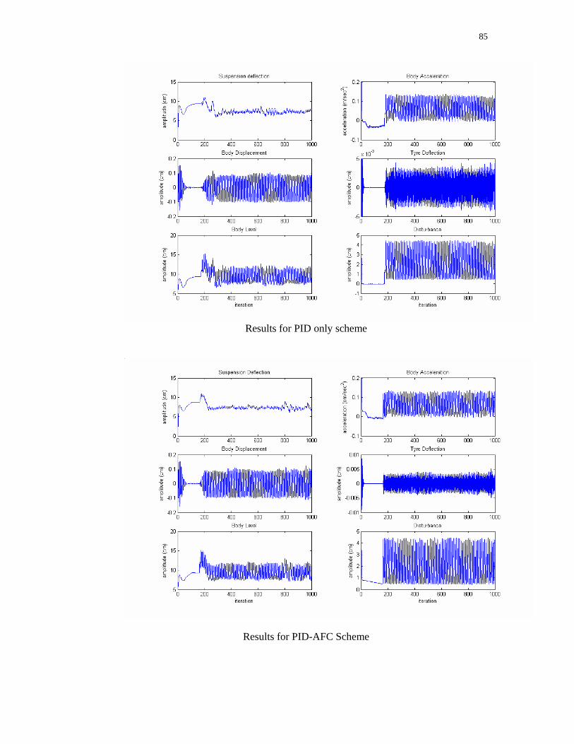
85
Results for PID only scheme
Results for PID-AFC Scheme

86
B. Results of the Experimental Study (Preliminary)
PID scheme (P=7 I=13 D=50)
PID scheme (P=7 I=13 D=55)
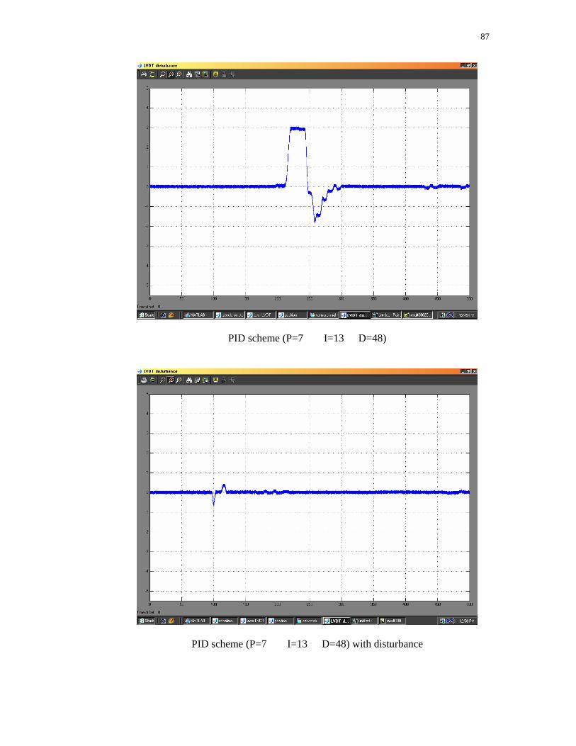
87
PID scheme (P=7 I=13 D=48)
PID scheme (P=7 I=13 D=48) with disturbance
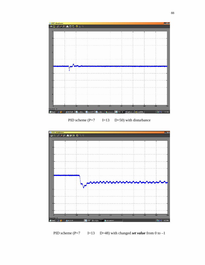
88
PID scheme (P=7 I=13 D=50) with disturbance
PID scheme (P=7 I=13 D=48) with changed set value from 0 to –1
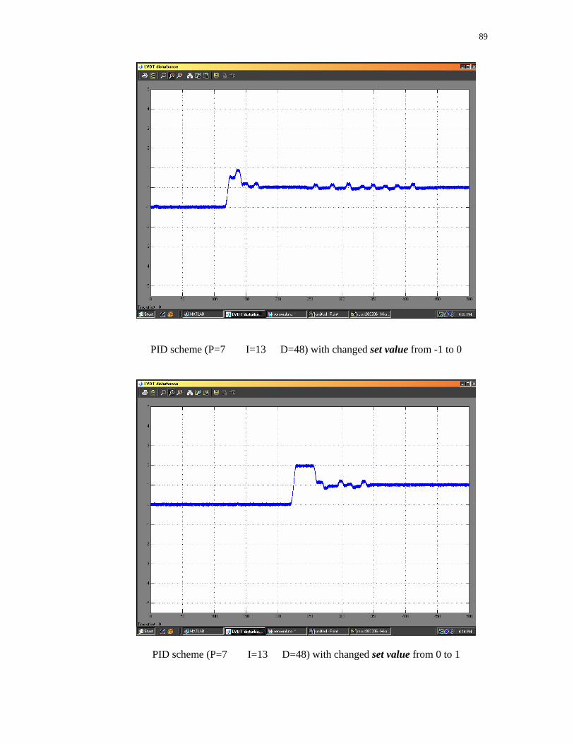
89
PID scheme (P=7 I=13 D=48) with changed set value from -1 to 0
PID scheme (P=7 I=13 D=48) with changed set value from 0 to 1
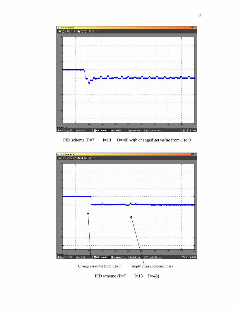
90
PID scheme (P=7 I=13 D=48) with changed set value from 1 to 0
Change set value from 1 to 0 Apply 20kg additional mass
PID scheme (P=7 I=13 D=48)
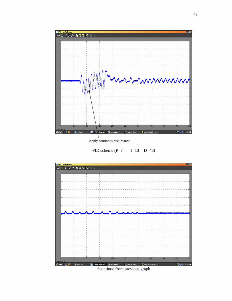
91
Apply continous disturbance
PID scheme (P=7 I=13 D=48)
*continue from previous graph
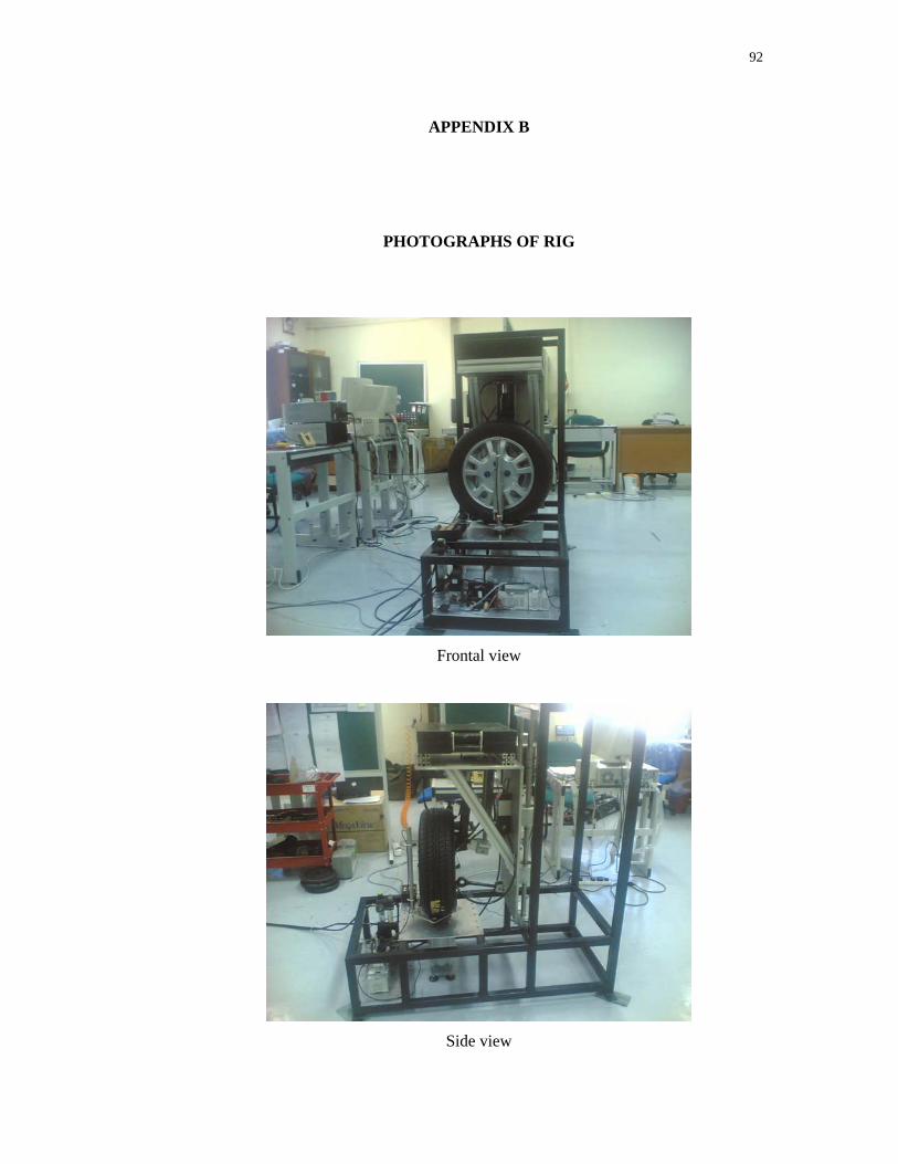
92
APPENDIX B
PHOTOGRAPHS OF RIG
Frontal view
Side view
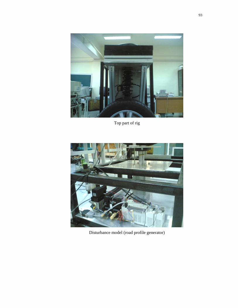
93
Top part of rig
Disturbance model (road profile generator)
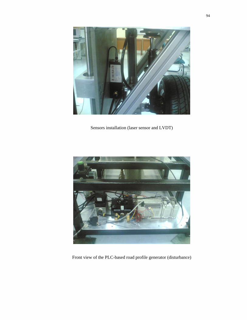
94
Sensors installation (laser sensor and LVDT)
Front view of the PLC-based road profile generator (disturbance)
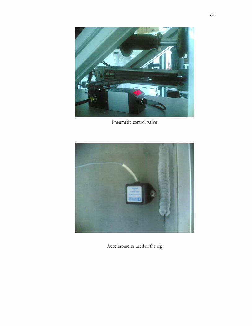
95
Pneumatic control valve
Accelerometer used in the rig
96
APPENDIX C
LIST OF PUBLICATIONS
1. Gigih Priyandoko, Musa Mailah, ‘Control Design of A Quarter Car
Suspension System using Fuzzy Logic Active Force Control’, Procs. of
ICOM05, KL, May 2005.
2. Gigih Priyandoko, Musa Mailah, ‘Control Design of A Quarter Car
Suspension System Using Iterative Fuzzy Logic Active Force Control’, Procs
of SITIA05, Surabaya, May 2005.
3. Gigih Priyandoko, Musa Mailah, ‘Fuzzy Logic Artificial Neural Network
Active Force Control for an Active Suspension of a Quarter Car’, Procs. of
ROVISP05, USM Penang, July 2005.
4. Md Zarhamdy M Zain, Gigih Priyandoko, Musa Mailah, ‘Hybrid Control
Scheme Incorporating AFC and Input Shaping Technique For A Suspension
System’, Procs. of SITIA07, Surabaya, May 2007.
5. Gigih Priyandoko, Musa Mailah, Hishamuddin Jamaluddin, ‘Particle Swarm
Optimization Neural Network Based Modelling of Vehicle Suspension
System’, Procs. of Regional Postgraduate Conference on Engineering and
Science 2006 (RPCES 2006), June 2006.
6. Gigih Priyandoko, Musa Mailah, ‘Adaptive Fuzzy Active Force Control
Applied to A Quarter Car Suspension System’, International Journal of
Simulation Modelling, Vol. 6, No. 1, March 2007, pp 25-36.
7. Gigih Priyandoko, Musa Mailah & Hishamuddin Jamaluddin, Vehicle Active
Suspension System Using Skyhook Adaptive Neuro Active Force Control, to
be submitted to Mechatronics (an International Journal), April 2007.
8. Md Zarhamdy M Zain, Gigih Priyandoko, Musa Mailah, S.Z. Hashim, M.O.
Tokhi and M.S. Alam, ‘Estimation Parameters of Hybrid Control Schemes
97
For Suspension System: A MOGA Approach’, accepted for presentation at
CIM07, 28-29 May 2007.
9. Gigih Priyandoko, Musa Mailah, Hishamuddin Jamaluddin, ‘Skyhook
Adaptive Neuro Active Force Control for An Active Suspension System’,
accepted for presentation at CIM07, May 2007.

98
APPENDIX D
ACHIEVEMENTS / OUTPUTS
A. INTERNATIONAL JOURNAL:
1. Gigih Priyandoko, Musa Mailah, ‘Adaptive Fuzzy Active Force Control Applied
to A Quarter Car Suspension System’, International Journal of Simulation
Modelling, Vol. 6, No. 1, March 2007, pp 25-36
2. Gigih Priyandoko, Musa Mailah & Hishamuddin Jamaluddin, Vehicle Active
Suspension System Using Skyhook Adaptive Neuro Active Force Control, to be
submitted to Mechatronics (an International Journal), April 2007.
B. INTERNATIONAL CONFERENCE:
1. Gigih Priyandoko, Musa Mailah, ‘Control Design of A Quarter Car
Suspension System using Fuzzy Logic Active Force Control’, Procs. of
ICOM05, KL, May 2005.
2. Gigih Priyandoko, Musa Mailah, ‘Control Design of A Quarter Car
Suspension System Using Iterative Fuzzy Logic Active Force Control’, Procs
of SITIA05, Surabaya, May 2005.
3. Gigih Priyandoko, Musa Mailah, ‘Fuzzy Logic Artificial Neural Network
Active Force Control for an Active Suspension of a Quarter Car’, Procs. of
ROVISP05, USM Penang, July 2005.
4. Md Zarhamdy M Zain, Gigih Priyandoko, Musa Mailah, ‘Hybrid Control
Scheme Incorporating AFC and Input Shaping Technique For A Suspension
System’, Procs. of SITIA07, Surabaya, May 2007.
5. Gigih Priyandoko, Musa Mailah, Hishamuddin Jamaluddin, ‘Particle Swarm
Optimization Neural Network Based Modelling of Vehicle Suspension
99
System’, Procs. of Regional Postgraduate Conference on Engineering and
Science 2006 (RPCES 2006), June 2006.
6. Md Zarhamdy M Zain, Gigih Priyandoko, Musa Mailah, S.Z. Hashim, M.O.
Tokhi and M.S. Alam, ‘Estimation Parameters of Hybrid Control Schemes
For Suspension System: A MOGA Approach’, accepted for presentation at
CIM07, 28-29 May 2007.
7. Gigih Priyandoko, Musa Mailah, Hishamuddin Jamaluddin, ‘Skyhook
Adaptive Neuro Active Force Control for An Active Suspension System’,
accepted for presentation at CIM07, May 2007.
C. PHD STUDENT:
1. Gigih Priyandoko, Intelligent Active Force Control of A Vehicle Suspension
System, June 2003-present.
D MENG STUDENT: 1. Mohd Rizal Ahmad @ Manap, Simulation and Experimental Analysis of An
Active Vehicle Suspension System, December 2006-present.