a . fuk yaw - ir.unimas.my of structural elements 24pgs.pdf · akhir sekali, 2 jenis liang akan...
TRANSCRIPT
1 O F STRUCTU RAL ELEMENTS FO R 5 TOR EY RESIDENTIAL C LASS DIE FLAT
A FUK YAW
niYersiti Malaysia Sarawak 2001
TA
A887 2001
658
PKHIOMAT MAKlUMAT AKAOEM IK
DESIGI OF STRUCTU RAL ELD IENTS FOR 5 STO REY RL IDE TIAL CLASS DIE FLAT
PuS1llhl111131 Mo ~ JI ~ i u II ( 1 IJrrrll mITI l SIA S bull
By
Au Fuk Yaw
A di ssertation submitted in partial ful fi llment of the requirements fOllhc d~gne of Bachelor or Engineering (Hans) in Civil Engineering
Fac ulty o f Engineering UN IVERSITY MALA YS1A SARA WAK
March 200 I
bull
rniHr~ili Ialay ~il Sllra al KOla ~amarahan
Il
BORANG PENYERAHAN TESIS
Juu ) DESIGN OF STRUCTU RAL ELEMENTS FOR 5-STO REY RLSI DENTIAL -CLASS DI E FLiT
~1IIr( II~ I l)llS ~IIIII
Saya U F U K YAW (1IURUF BESA R)
Illlngtlu mLmb~llarlr al1 t~si ini dllllpan (11 Pll~t KllIdmu II Jhhm1l1 kJdCfT1ik t nh ~1 1alayiu sJroJ 1 dngJIl s)ltln l ~ariJl lq~unaan s~p rli hrihUl
I I hdnlilik k~nij pro middotl ~daluh lf j bJ ili namit rnul lluIIInJan r4lIuli)m )~bill ui prollk lhlwtllhl UI
dbItH ukh LIlI MAS hlllmilJ n)ltl ndII1h lep l1l1) iIiQ L l IMAS 0 Nalhah wlll1an tli dulam bCnlu k~r1as U1U IIlInl haniJ blJlLh diudl dllgan kchcHiifau tcrtuli
uanllhJJ pcnul ilt 3 flu Khrdm1I Mtllluil idt ALIJcnll h LJN IIIA~ ~hhcnarkan TTltrnhll n ltthnoll mUll ~nalltn IIIlfd J
I K ~rtus prokl hanyu boldl dlt crhnloan Jngm h ~lxlUmln patu i U~)ariJ ll m YJlh ldnli1h nll l1 glkut ~Jdar ~ un~ dlpcrsclUiul Jdlli bull Sa_lIIT1~m h~ntranliiJ-lk l1l~mbnO liln i rrU~1ltlkau Ji mCmbUil -alll1rin ~r1a pnljd 11I l ~hilg j Mhm r~n tlkarllf1 Lll if llar illgtt ilUl rrngJlldn linggl
() bullbull ~ilA tantJ m ( )
CJ St Ut (~kll)oliJJlllullll1 maklulIlt1 ) ~n~ bLrlnnlh cdlmlJHII1 allt k~~~JItJIIgiUl
MJ II ) -i a lcplrli ) tllj hrmaktub tlJ llllaOl AK TJ R 11 I RA~~ 11 19-1 j
c=J n RilAIl ( l n~ill1 d ungj muIUI11~H 11- RIIA) ) 1JI~ Idah JiICIllUiJn (kh t1tgumai Badn di mall) pln) dl(J i kJ1J ~Iuo lan kan )
[ZJ TIDAK II-I(II II)
li l~ilhhan 11~1
aJJ~~I fl~V7 -1I ~IJA I ~ IN 11 lJl Iq (TI NI) I I IN( 1PI ltYI II II
amJI IdIP 129 AR NG ROA D 136
AR ANlt BA RA l_ KIf II ING )~Ri 11 11gt
(W M it III 111)01
( alna 1) 10) dll J
1tr1 h middot h ~1 lt( 21Ml l I nkh- q q 21V J I
II
APPROVAL SHEET
1 hi s project report attached here to entitled Design of structural elements for 5 ~tore)
resi d~ ntial Class DIE flat prepare and submitted by Au Fuk Yaw in partial fulfillment otthe requirements fo r the degree o f Bachelor o f Engineering (Civi l) is hereby accepkltl
~~~~-shyDated q1uV I
( Ur N g Chee KJ100n )
Lecturer Civil Engineering Department Facult y of - ngin ee ri ng Uni versity Malaysia Sarawak
2lt~ -----+~~----------shy Date -----=-------1------shy( Au tUK 129 Jalan ang Barat 93250 Kucl ng Sarawak
III
ACKNOWLEDGEMENT
First ly I would like to take thi s 0ppol1unity to ex press my deep ly appreciat ion to
my project s uperviso r Dr Ng Chee Kh oon for hi s guidances and va luab le adv ice UIIder
his superv ision I managed to overcome a ll the design pro blems that encounter during
progress Furthenllo re iiom his courtesy sugges ti on I have my lirst dralts to begin this
thesis
The other persons I wish to thanks is Ir Wi lson Voon Managing d irctQ r o f
Hashim amp Neh (Sawarak)Sd n Bhd for his permission to ha ve a lJ th e calculation sh~cts
and detailing I needed
Last ly I also no t forgotten to thanks those had kindly hdping n1 in this project
Their parts make thi s thes is more meaningful to me
tV
ABSTRACT
The des ign proiect encompassed in thi s di ssertation namely design of structural
element for a S-storey res idential building using vari ous design so ft wa res lhe output
results generated by these softwares were compared and any differences if availab le
were commented accordingly
In re inforced concrete slabs design there were 2 so ft wares selected in d e~ign and
the compariso n of results was carried out thereatier Both softwares were Rein forced
Concrete Co uncil RCC spreadsheet (Ree 9-1 Two -IFaY slab (Iable) and Staacli ll
Interactive Design REI 223 w 32 bil The latter so ftware design slabs to ACi 318 (1995)
code req uirement while Re in fo rced Concrete Counci l RCC spreadsheet [ RCC 9-1 Twoshy
way slahs (Iuble)] design slabs to BS 811 0 ( 1985) code A continuous slab lllurked as
S 15 to S21 loca ted at typical floor was designed using both software
In reinforced concrete beam design 3 sofl wares were adopted namel y AxisVm
Vel 5 () (beam and Re inforced Concrete Council RC C spreadshee t (RCCI I Elellellt
Design) A continuous beam marked as TBl to TB4 were run using the aboveshy
mentioned softwares Likewise output results from these softwares were malyzed and
co mpared
v
In reinforced conc rete co lum n des ign 2 softwares were adopted namely
Reinforced Concre te Council RCC spreadsheet (Ree54 column Design) and ShorlCol
spreadshee t Tlvo critical co lumns marked as C I and C3 we re chosen for design and
comparison purposes
VI
ABSTRAK
Duld m projek tahun akhir ini pelbagai peri sian kompuler akan digunakan unl u~
luj uan merekabentuk bangunan Bahagian bangunan yang akan direka dengan
menggunakan peri sian kompuler merangkumi 3 e lemen penting bagunan iai lu rasuk
konkri t lenulang papak dan tiang Kesesuaian pri sian ini akan juga dinilai dari s~g i
keupayaan dan kej iluannya Dalam bahagian ras uk konkrit tertnlang 4 ras uk krili ku l
tdall dipilih daripada tingkal pertama manakala papak pula S I 5 ke S27 dipilih pada
lingkal yang sa rna Akhir sekali 2 jenis liang akan direkabentuk iailu satu pada bahagian
da laman dan salu pula pada bahagian luaran bang unan
Dalam lingkat pertama satu rasuk bcncrusan yang terdiri daripada 4 rentang iailll
TBI ke TB4 dipilih sebagai rasuk kaj ian Ini adalah di sebabkan sa lah salu rentang rasuk
ini ke na menyokong beban ling dari lingkal alas Ini mcnyeb hkan keralan rcnlas rasuk
ini lebih besar daripada ya ng lain
Dua peri sian lltam a akan digunakan unlllk menca ri nomenl envelop and shear
envelop 2 perisi an ini ad ala h AxisVm Ver50 and Cbeam Keputusa n daripada kecluashy
dua perisian ini akan dini lai Keburukkan kedua-dua ini ialah ia lidak nHm bekalk an
sebarang rekabetuk tenulang bagi rasuk maka peri sian la in per lu di gu nakan Rel1loreed
Concrele Council RCC spreodsheel (RCC II poundIemel7l Design) telah dipilih sebagui
peri sian talllhahan bagi meng ira kesesuaian tertula ng
VI I
Selain itu 2 lagi pe ri sian ya ng akan digunakan dalam project bagi merckaben tuk
konkr it bertul ang bagi papak Perisia n-perisian ini ia lah Reinorced Concretc Council
RC C spreads heel [RCC9-1 Two -way slabs (Iable)] (Kode paiwaian BS811 0 ( 1985) and
Staad III Interac ti ve Design ReI 22Jw 32-bit (Kode AC I 318 (1995 ) Papa k-papak dari
S IS ke S27 a kan direka dan nila inya dibandi ng daripada kedua-dua peri sian ini
Akh irnya2 lagi peri sian la in digunakan unlu k mereka li ang konkrit berlel1 ul ang
ia itu Reinforced Concrete Council RCC spreadsheet (RCC54 Column deign) dengan
kode BS8 11 0 (J 985) dan ShortCol denga n kode ACI J 8 ( 995) Ke pu lwunn ya akan
din i lai dan d i band i ng berdasa rkan kej ituannya
VII
TABLE OF COlTE~S
PAGECONTESTS
IIBORANG PEN YERAHAN THESIS
I I 1 APPROVAL SHEET
IVACK OW l EDG EME T
VABSTRACT (I NGLISH)
VlJARSTRACT (MELA YU)
CII APTER 1
I I Int roducti on
212 Project Backgro und
J Software General out look )
CIIAPTER 2
521 Design Element
2 I Structural EIement Design for 5-Storey Residential Class DIE- fl at 5
622 Design Procedures
221 Slab Design Method 6
9222 Load Transfer Condition
1823 Structural Design So ft ware
23 1 Reinforced Concrete Slab Design 18
231 1 Staod III Iterative Design VC I~23w 18
2 312 Reinforced Concrete Counc il
RCC spreadsheet rlRCC two way Iab (tab le)] 22
) - _ j - Reinforced Concrete Beam 2middot1
232 1 Ax isV m VerS O ~-I
2 32 2 Cbeam 3()
233 Reinforced Concrete Co uncil RCC spreadsheet
(RCC 1 1 Element Design) ~7
2331 Re inforcment Design 37
2332 Slab Link design 39
234 Rei n forced Concrete Column 41
234 1 Predeterminatio n of Col uml1 Size anJ
Reinforcement 41
23 42 ShortCol Spreadshee t 44
2342 Re inforced Concre te Council RCC
Spreadsheet ( RCC54 Column Degtign) -17
CHArTER 3
5030 COMPARlSlON OF SOFTWARE OUTPUT RESULTS
50
64
31 Reinforced Concrete slab marked as SI S to S27
Reinforced Concrete Beal11
64321 4-span Conti nuous Bea l11 marked as TB I to TB4
3 2 Overhangjng 2 Spans Continuous beam
7~marked as TI35S toTB59
7633 Re in forced Concrete Column
CII AITER -4
9740 CONCLUSION
98
AIIElDIX
CHAPTER 1
11 IlITROOlICTION
Nowadays most of the engineering film s usc software to design or so lve complex
problems Although some of the software are relati vely expensive but for long term
investment it will produce beneftt and always remain compatible There are many typc
of structural software in the market but most ofthcm are diflicult to use Fltrlhcrmorc
some of the software are limi ted onl y for particular country standard 50 in 0rdcr to
search for the suitab le software several software wi ll be compared in varies asptct in thi s
thesis
Most of the software deve lopers provide student version or demo in i n l~rn c l so
the compl Ie soft ware cannot be obtain But in this thesis several ~o lhmre il l be use
together to solve for outpu t result and des ign for final reinforcement Ihe software are
AxisVM Ver50 Slaad fff Reinforced Conaele CouncilRCC and Cbeam The resul t
generated will be compare and the diffe rent were studied The code of practice used are
BS8110 (1985) and ACI31 8( 1995)
121 PrQjec l Background
The proposed Royal Malays ia Naval Base to be situa ted at Te luk Sepanga r K Ita
Kinaba lu Sabah wil l become the biggest naval base throughout Malaysia The project
will take approximately 5 years to complete where there are eight phases o f build ing
constructi on works The 8 packages of design project consists of Residential ( 15
buildings) Wo rkshops amp Stores (11 buildings) Offices (7 bu il dings) Com munity
Buildi ngs (7 hu ildings) Recreatio ns (5 buildings) Trainings (7 bu ildings) aal Air
Station (4 buildings) and Hospital (l buildings)
More and mo re amateur nava l aImed forces troops are recruited yearly by the
Defence Mini stry caus ing the shortage of place for accommodation in Sahah wh ich is
currentl y face by the a uthority He nce expenses have been a llocated to build the
res idential flat in orde r to tempo rary so lve the res idential problem
The design project fl a t DIE is one of the bui ld ings in packag I (Residential
phase) The tla t is 175 in height and consists of 3 apart me nt in each storey making a
(otal o f 14 apanments for th e who le block For each storey inc ludi ng the car par
basement or the gro und tloo r the height is design to be similar whicb is 3200ml11 The
length of the flat is 466m wh ile the wid th is 149m On grou nd surface the to ta l area uf
th e who le buildi ng is 694 34m2 An apartment with a to tal area of 15 1 5111 2 has 3
bedroom 2 toilet I living room J kitchen 1 utility roo m 1 sto re roOIll ami I balcony
The res idential flat will take approx imately eight months to be completed Upon
completion it can acco mmodate 75 people for the who le block (re fer to a ppe nd ix)
2
13 Software General Outlook
Shortcol is a spreadsheet downloaded from websites which is writte n by Yakov
Po lya kon P E T he spreadsheet design co lumn to ACI 3 I 8 (1985) code req uirement
Spreadsheet parameters in both S l and Engli sh unit can be ente red inside the sp readsheet
In this design project ShortCol was used to generate iteracti o l1 diagram fo r _ crilical
co l urn ns
Stood III is a structural ana lys is software developed by Resea rch Engineer a
netguru company incorporated in 98 I Staad III provides 2D3D graphica l interface
generat using Fini te Element Ana lysis method In thi s project S taad 111 ll ef( cti vc Design
Ie 223 was used fo r s labs design to ACI J I 8 (1995) code
(beam is a software deve loped by BenArit Ltd and the aut hor is el i Renari The
so ftware can run ana lysis up to 10 spanning beam In thi s design project (heam was
used to generated shear force enve lopes and bend ing moment en velopes lor - pan
conti nuo us beam marked as S I to S27
AxisVm Vel 50 is a Finite e lement Analysis software tool fo r c iv il engineers
The sotiware was deve loped by Inter-Cad KFT in 199 1 In this design proj ect Axis Vm
Ver 50 was used to obtain the shear force e nvelopes and bend ing momentlnve lopes of
critical beam marked as TB I to TB4
Reinforced Co ncrete Council was formed in 1988 There are a llogethe r 26 Exce l
spreads heets wri tten by professiona l of this cou ncil A far J i this proj~c t was concerned
3
RCC II poundlemen Design RCC9-1 Two-way slabs (Table) and RCC53 Column Design
we re used for structural element design of this 5-storey residential building
4
CHAPTER 2
20 DESIGN ELEMENTS
21 St ructural Ekments Design for S-Storey Residential Class DE Flat
The econom ical and safe ty structural deigns are the main ~spects to be
considerate in thi s Turnkey projec t Designer had to design base on the gtrccifica ti on that
had been agreed between client and develope r
There vere about 194 beams in each floor which total approx imately abo ut 950
beams for the whole bui Iding The minimum beam width recom mended was I Omm and
the minimum beam depth were 500mm and 400mm for main beam and ~co ndary beam
respec ti vely NormaJl y the length of secondary beam was less than 6m and ca lTY less
loading compare with mai n beam
The type of rei nforcements used in thi s project was high yield tensile hot rolled
stee ls (Y type steels) The max imum number and size of bar cd are base on the beam
width (Table Reinforcement Data) For exa mple 2Y25 for top and 3Y25 Inr bottom
reinforcement is suitabl e [or beam width of 200111 111 and can be provided into layers For
shear link case its always maintai n at size R8 and might be reach to 2R-75 the in some
criti cal cases
5
For the slab cases the minimum depth recommended is 11Smm and the bar
usua lly kept to YI O-J OO for top and Y10-200 for bottom There is one slilTener
suppoJ1illg the beam from 4 to I lloor The max imum cross-sect ional area for this
~tirkner ISOm m X ISOmm For column des ign staggered columns were to be designed
as their size gradual ly increased from top fl oor to ground
22 Design Procedures
221 Siah Des ign Method
By using two so ftwares slabs are run one after another fo r thi s project al though
they are conti nuously connected For example let take a 4-span slab marked asS I
82 S3 and S4 as shown in Figure 2 1 Conventi ona ll y these types of continuous
joined slabs are supposed to be designed cont inuously on four spans basis (re ler to Figure
21 (a)) However thi s design is different from the conventi ona l method a~ the slabs arc
treated individuall y where they sho uld be des ign simply suppo rted for every single slab
(refer to Figure 2 1(b)) To save time while avo iding the unnecesar) ted ious design
jobs thi s type of des ign is being adopted Earl ier discussions on the restriction of
rein fo rcement where the top and bottom steel are set at YIO-200 and YIO-300
respectivel y sho uld also be taken in to consideration in the contex t of design
The usage of these 2 types of reinforcement wi ll re main although les
rein fo rcement than needed may occur 111 some cases For example conti nuo us edge
between slab markedS I and S2 need less reinforcement as it possible to be reduced
6
according to the codes (refer to Figure 21) For thi s project however all slabs are
adhered to the fi xed reinforcement stated above
Nevenheless some bi g heavy slabs may need more reinforcement If thi s
condi tion take place in thi s project the slab should be split into 2 small slabs in between
by adding an ex tra beam undemeath This type of amendment is necessary to lit the
reinforcement mentioned above into all slabs of the building ln real-tin lc practice
ambiguities migbt arise arguing that the design is not cost effective However reduction
in the slab depth from 12Smm to II Smm subsequently compensates each other in tenn of
costs and expenses
a In con ventional design slab marked S I S2 S3 and middotSmiddot are designed
continuously because they are continuously joined with each othe r
7
51 53
o
b In th is project each slab was designed as simply supported and e ~ I) slabs
parameters to he keyed in separated spreadsheet
Fig 2 1 Bending moment for a typica l 4-span continuous slab designed two dilTc[cnt
method
8
222 Load T ransfer Condition
EDGEl
SIS EDGE 2EDGE 4
EDGE 3
SUPPORT REACTIONS IlkN m char uno)
(See Figure 310)
EDGE 1 J F-Gl O 0351
Dead kNtm 43 2 Imposed kNtm 331
Vs kNtm 114
EDGE 2 EDGE 3 G2 j 2 F-G 0290 0526 358 648 274 497 94 170
EDGE 4 F 2-1 0290 358 274 9~~
Fig2 2 Support reactions for un[aclored dead and Ijve load s of s lab marked S 5
II is importan t to transfer the reaction adcyuatel y from the four s ide of the lab to
th e main or secondary beam as shown in Fig 22 Fig 23 and Fig 24
9
In Figure 22 there is a section showi ng all 4 slab sides reaction by separating
them into unfactored li ve load a nd un factored dead load inside the spradhee t These 4
s lab s ides are addit ionall y labeled as Edge 1 Edge 2 Edge 3 and Edge 4 for casy
recognition The react ions of the 4 slab s ides are to be transferred acco rdingly as uniform
distributed loads on related beam Note that beam marked as TB63 T870 TB 11 and
TB25 respec tive ly
J1
~ ~
I 1
F ~ 00
0 1
Jl ~ I fJ 0 bull-
oil llLi SalT
IB H
1 5
o lD N bull
CXl
bull lt
Fig 23 Key plan extracted showing reactions on a few slabs transferred to related beams
10
lEDGE 11 -------------- --- - - - - - TBII
lEDGE 41 TBo3 15 TB70 lEDGE 21
- - - --- shy
lEDGE 31
Fig 24 Reactions on slab marked SJ 5 transferred to relattd beam as unitoml
distributed load
If the main beam SUPP0rlS another secondary beam the reaction of the secondary
beam will act as concentrated load on the maim beam [n Figure 23 the main beams
mark ed TB2 ~ and TB I 0 supp0rled the secondary beam marked TB60 The end reaction
of secondary beams will hence behave as concentrated loads on the mail beam The
concentrated loads are supposed to be separa ted into unfac lored dead l oud ~ and
unfactored li ve loads to ease the key-in of data during the analysis The reac tion on how
slab marked S I S2 S3 and S4 are shifted to main beam marked TB I I TB70 and
TB25 as uniformed di stributed loads is shown in Fig 24
I I
r J
i
~
SI7 SI S S16 GueSlrvom
kite en toilet
J
bull middot S26A S27 Ibby Lvlng
J
li g2S Location of continuous slab marked asS IS to S27 ~xlrnc led from I lloor ~y plan
12
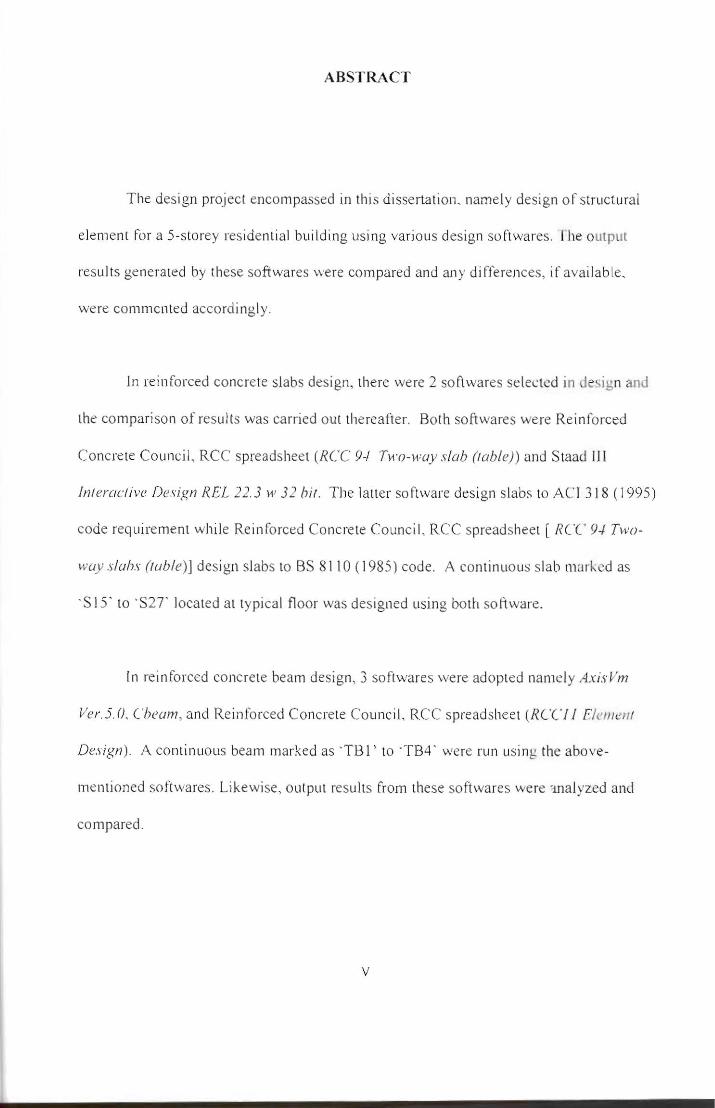
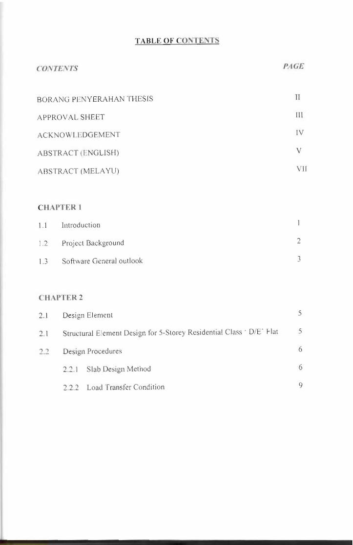
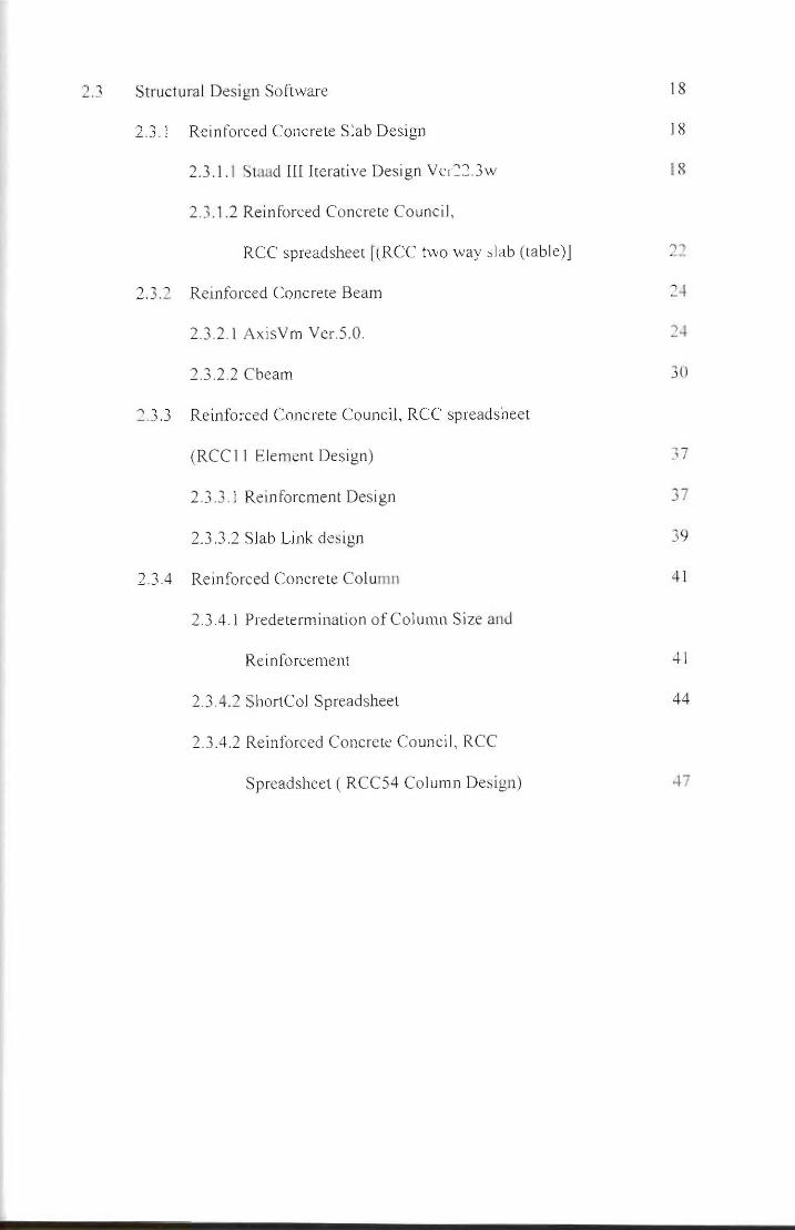
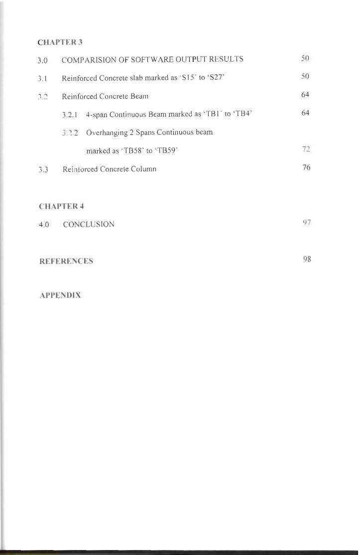
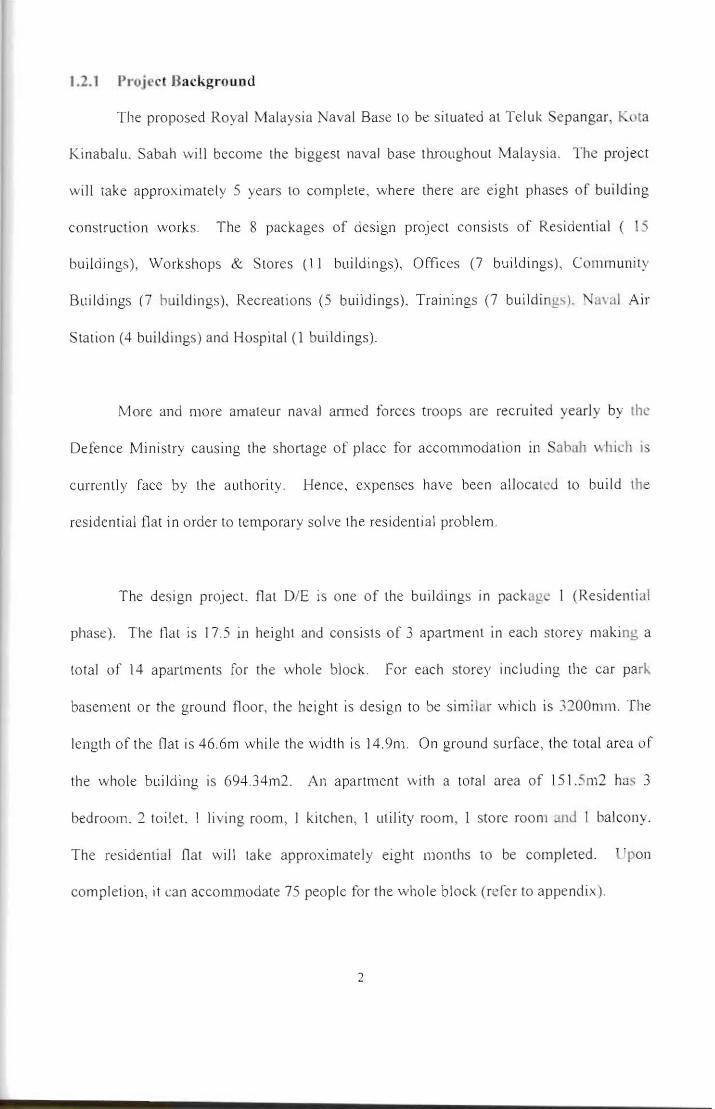
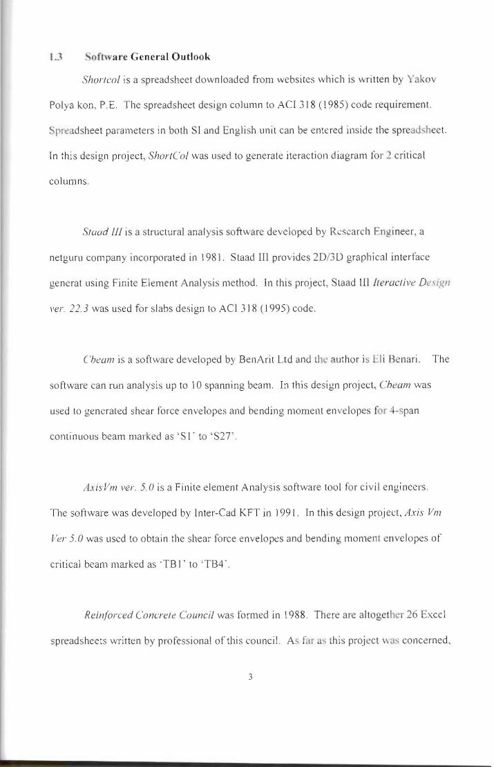
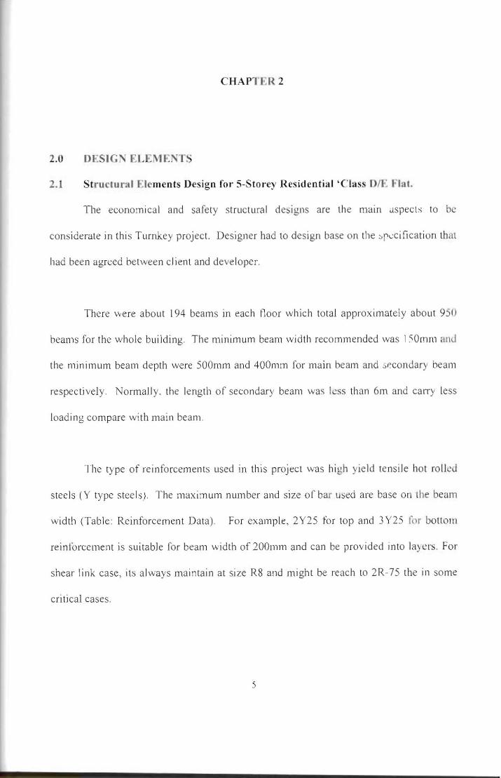
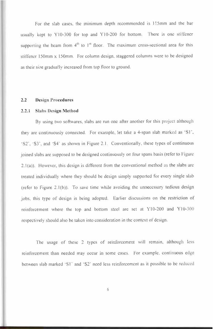
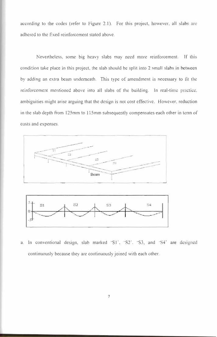
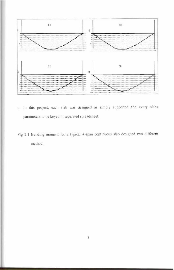
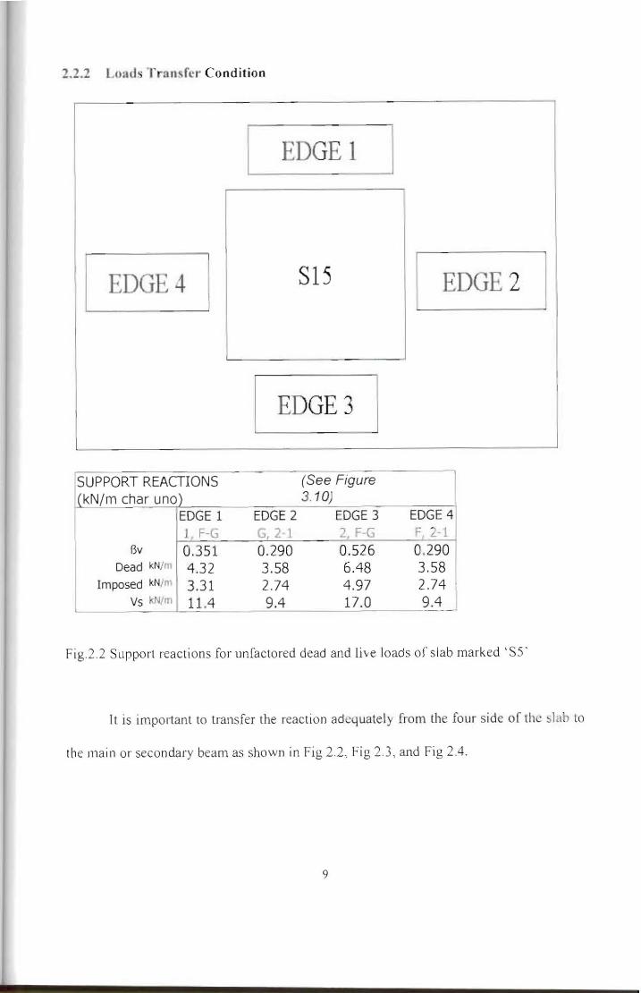
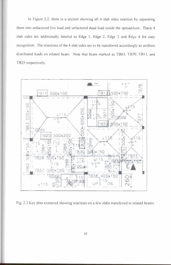
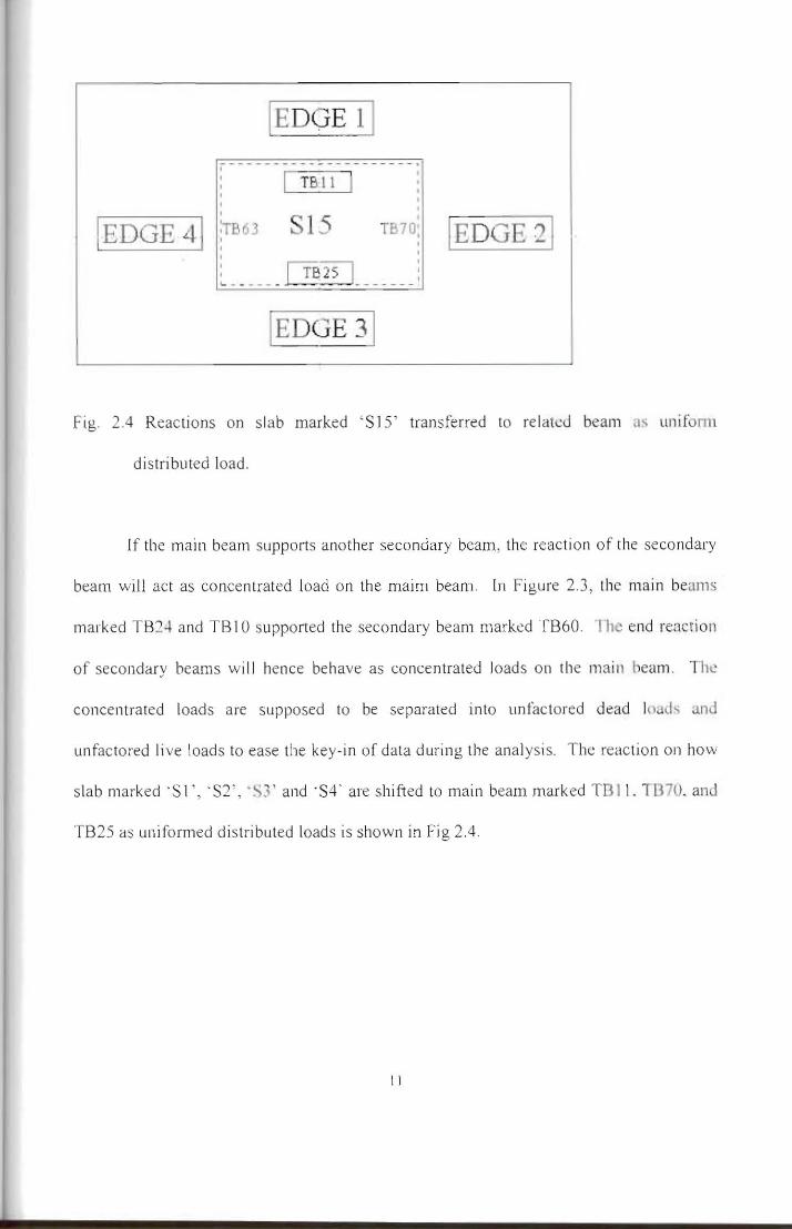
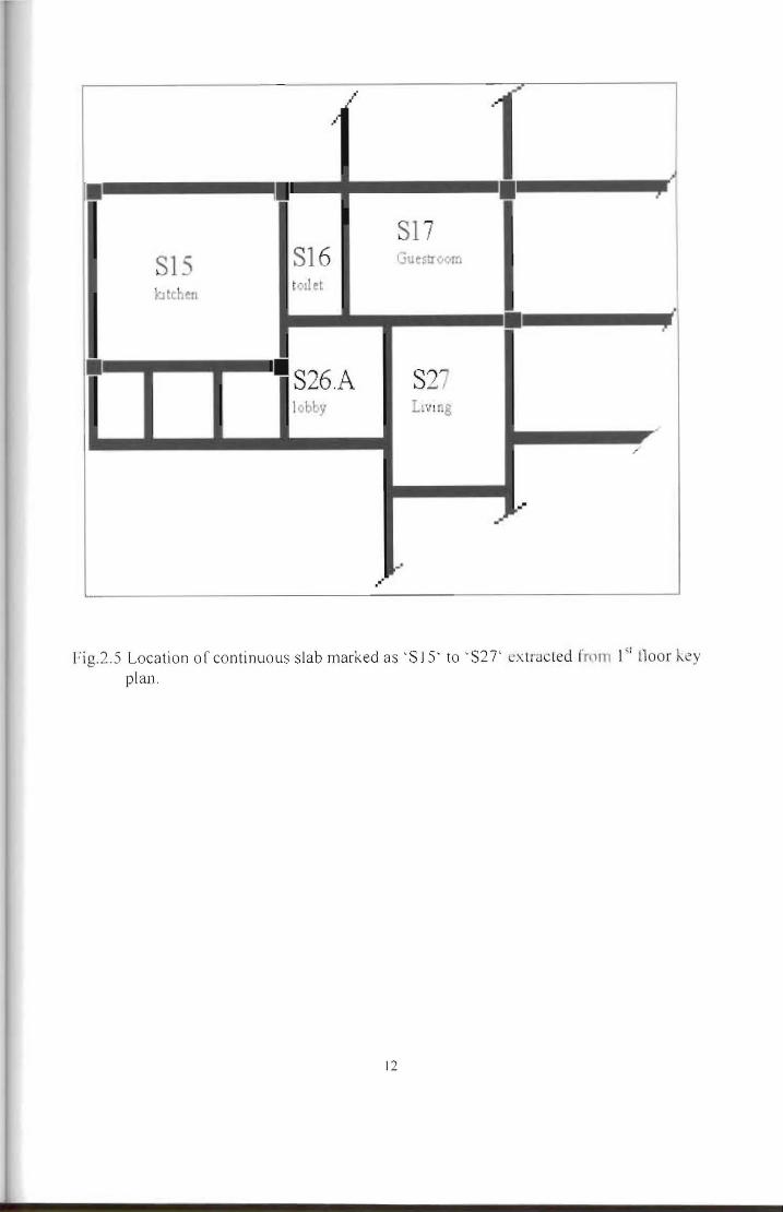
r J
i
~
SI7 SI S S16 GueSlrvom
kite en toilet
J
bull middot S26A S27 Ibby Lvlng
J
li g2S Location of continuous slab marked asS IS to S27 ~xlrnc led from I lloor ~y plan
12