(huruf besar) - connecting repositories · ke atas konsep berkenaan untuk mengenalpasti...
TRANSCRIPT
UNIVERSITI TEKNOLOGI MALAYSIA
UTM/RMC/F/0024 (1998)
BORANG PENGESAHAN LAPORAN AKHIR PENYELIDIKAN
TAJUK PROJEK : DESIGN AND DEVELOPMENT OF ROTATING SLEEVE REFRIGERANT COMPRESSOR
Saya ___PROF DR MD NOR MUSA _________________________________________________ (HURUF BESAR)
Mengaku membenarkan Laporan Akhir Penyelidikan ini disimpan di Perpustakaan Universiti Teknologi Malaysia dengan syarat-syarat kegunaan seperti berikut :
1. Laporan Akhir Penyelidikan ini adalah hakmilik Universiti Teknologi Malaysia.
2. Perpustakaan Universiti Teknologi Malaysia dibenarkan membuat salinan untuk tujuan rujukan sahaja.
3. Perpustakaan dibenarkan membuat penjualan salinan Laporan Akhir
Penyelidikan ini bagi kategori TIDAK TERHAD.
4. * Sila tandakan ( / )
SULIT (Mengandungi maklumat yang berdarjah keselamatan atau Kepentingan Malaysia seperti yang termaktub di dalam AKTA RAHSIA RASMI 1972). TERHAD (Mengandungi maklumat TERHAD yang telah ditentukan oleh Organisasi/badan di mana penyelidikan dijalankan). TIDAK TERHAD TANDATANGAN KETUA PENYELIDIK
Nama & Cop Ketua Penyelidik Tarikh : _________________
CATATAN : * Jika Laporan Akhir Penyelidikan ini SULIT atau TERHAD, sila lampirkan surat daripada pihak berkuasa/organisasi berkenaan dengan menyatakan sekali sebab dan tempoh laporan ini perlu dikelaskan sebagai SULIT dan TERHAD.
Lampiran 20
VOT 71811
DESIGN AND DEVELOPMENT OF ROTATING-SLEEVE REFRIGERANT
COMPRESSOR
(REKABENTUK DAN PEMBANGUNAN PEMAMPAT REFRIGERAN SILINDER BERPUTAR)
PROF DR MD NOR MUSA
RESEARCH VOTE NO: 71811
Jabatan Matematik Fakulti Sains
Universiti Teknologi Malaysia
2002

ACKNOWLEDGEMENT
First of all, thanks to Allah SWT for giving me the strength and the chances in
completing this project.
Secondly, I wish to express my sincere gratitude to the Ministry of Science,
technology and Innovation (MOSTI) for supporting the project via research grant. Also
included, RMC (Research Management Centre) for their commitment in managing the
project as well as providing background support to research projects in UTM generally and
especially on the project.
Millions of gratitude to members of the faculty of mechanical engineering, UTM
for providing supports facilities and man power thus making the research another
successful breakthrough which makes UTM proud.
ABSTRACT
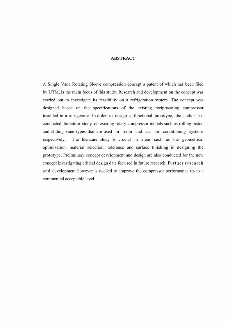
A Single Vane Rotating Sleeve compression concept a patent of which has been filed
by UTM, is the main focus of this study. Research and development on the concept was
carried out to investigate its feasibility on a refrigeration system. The concept was
designed based on the specifications of the existing reciprocating compressor
installed in a refrigerator. In order to design a functional prototype, the author has
conducted literature study on existing rotary compressor models such as rolling piston
and sliding vane types that are used in room and car air conditioning systems
respectively. The literature study is crucial in areas such as the geometrical
optimization, material selection, tolerance and surface finishing in designing the
prototype. Preliminary concept development and design are also conducted for the new
concept investigating critical design data for used in future research. Further research
and development however is needed to improve the compressor performance up to a
commercial acceptable level.
ABSTRAK
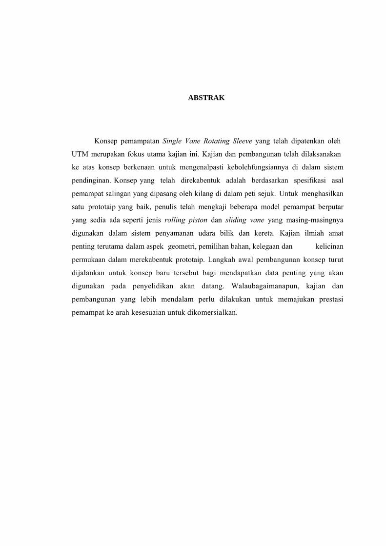
Konsep pemampatan Single Vane Rotating Sleeve yang telah dipatenkan oleh
UTM merupakan fokus utama kajian ini. Kajian dan pembangunan telah dilaksanakan
ke atas konsep berkenaan untuk mengenalpasti kebolehfungsiannya di dalam sistem
pendinginan. Konsep yang telah direkabentuk adalah berdasarkan spesifikasi asal
pemampat salingan yang dipasang oleh kilang di dalam peti sejuk. Untuk menghasilkan
satu prototaip yang baik, penulis telah mengkaji beberapa model pemampat berputar
yang sedia ada seperti jenis rolling piston dan sliding vane yang masing-masingnya
digunakan dalam sistem penyamanan udara bilik dan kereta. Kajian ilmiah amat
penting terutama dalam aspek geometri, pemilihan bahan, kelegaan dan kelicinan
permukaan dalam merekabentuk prototaip. Langkah awal pembangunan konsep turut
dijalankan untuk konsep baru tersebut bagi mendapatkan data penting yang akan
digunakan pada penyelidikan akan datang. Walaubagaimanapun, kajian dan
pembangunan yang lebih mendalam perlu dilakukan untuk memajukan prestasi
pemampat ke arah kesesuaian untuk dikomersialkan.
TABLE OF CONTENTS
CHAPTER TITLE PAGE
ACKNOWLEDGEMENT i
ABSTRACT ii
ABSTRAK iii
TABLE OF CONTENT iv
LIST OF TABLES vii
LIST OF FIGURES viii
LIST OF SYMBOLS x LIST OF APPENDICES xii
1 INTRODUCTION 1
1.1 Fundamental of Refrigeration 1
1.2 Refrigerating Compressor 2
1.3 Research Overview 5
1.4 Problem Statement 7
1.5 Significant of Research 8
1.6 Objective of Research 8
2 DESCRIPTIONS AND REVIEWS OF REFRIGERANT
COMPRESSOR 10
2.1 Introduction 10
2.2 Descriptions of Compressors 10
2.2.1 Rotary Compressor 10
2.2.1.1 Sliding Vane Rotary Compressor 11
2.2.1.2 Single and Multivane Rotary
Compressor 12
2.2.1.3 Rolling Piston Rotary Compressor 14
2.2.2 Reciprocating Compressor 16
2.3 Reviews 17
2.3.1 Patents Review 17
2.3.1.1 Patent of Rolling Piston Rotary
Compressor 18
2.3.1.2 Patent of Sliding Vane Rotary
Compressor 22
2.3.2 Literature Review 24
2.3.2.1 Design Geometry 24
2.3.2.2 Performance 25
2.3.2.3 Leakage 28
2.3.2.4 Material Application 30
2.3.3 Design Review 32
2.3.3.1 Reciprocating Compressor Design
Review 32
2.3.3.2 Rolling Piston Rotary Compressor
Design Review 33
2.3.3.3 Sliding Vane Rotary Compressor
Design Review 35
2.4 Conclusion 39
3 COMPRESSOR DESIGN AND DEVELOPMENT 38
3.1 Introduction 38
3.2 Design Step of New Compressor 38
3.2.1 Design of Compression Concept 38
3.2.2 Geometry Design 39
3.2.2.1 Geometry of Compression Concept 39
3.2.2.2 Geometry of Vane 44
3.2.2.3 Geometry of Rotor 45
3.2.2.4 Geometry of Sleeve 46
3.2.3 Discharge Angle Calculation 47
3.2.4 Design of Compression Component 48
4 CONCLUSION AND SUGGESTIONS 51
4.1 Conclusion 51
4.2 Suggestions 52
REFERENCES 53
Appendices A – C 57-65
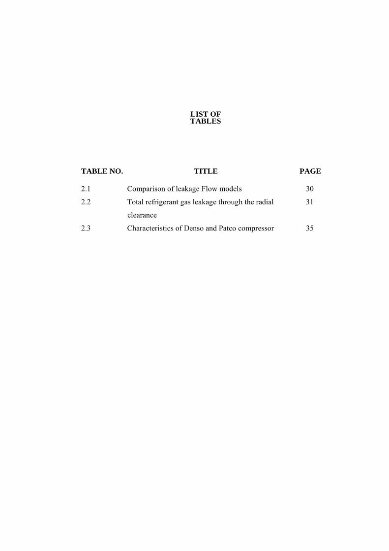
LIST OF TABLES
TABLE NO. TITLE PAGE
2.1 Comparison of leakage Flow models 30
2.2 Total refrigerant gas leakage through the radial 31
clearance
2.3 Characteristics of Denso and Patco compressor 35
LIST OF FIGURES
FIGURE NO.
TITLE PAGE
1.1 Schematic diagram of refrigeration system 2
1.2 Classification of compressor 3
1.3 Photograph of hermetic reciprocating compressor 4
1.4 Photograph of semi-hermetic compressor 4
1.5 Open compressor assembly type (a) Complete 5
assembly of compressor (b) Photo of
open compressor
1.6 Concept of single vane rotating sleeve rotary 6
compressor
1.7 Operation of single vane rotating sleeve rotary 7
compressor concept
2.1 Illustration of sliding vane rotary compressor with 4 11
vanes
2.2 Slots arrangements in rotor 12
2.3 Diagram of single and multivane rotary compressor 13
2.4 Illustration of rolling piston rotary compressor 15
2.5 Operation principle of rolling piston rotary 15
compressor
2.6 Operation principle of a reciprocating compressor 16
2.7 Innovation of suction inlet rolling piston rotary 19
compressor by Dreiman, N. I.
2.8 Sequence operation of two-orifice discharge method 20
2.9 Dual chamber rolling piston rotary compressor 21
2.10 Operating principle of dual chamber rolling piston 21 rotary compressor
2.11 Dual chamber sliding vane rotary compressor 23
patented by Adalbert and Visiotis
2.12 Configuration of dual chamber sliding vane rotary 23
compressor patented by Cavalleri
2.13 Geometry of oil-less rotary vane compressor 24
2.14 Compression principle of advanced rolling piston 28
rotary compressor
2.15 Definition points of internal leakage paths by Reed 29
and Hamilton
2.16 Magnitude of internal leakage 32
2.17 Leakage paths in rotary compressor modelled by 32
Rodgers and Nieter
2.18 Cylinder block for sliding vane rotary compressor (a) 36
Patco compressor (b) Denso compressor
2.19 Compartments boundaries of sliding vane rotary 36
compressor (a) Patco compressor (b)
Denso compressor
3.1 Basic geometry of compression concept 39
3.2 Geometry of compressor concept 40
3.3 Suction port position of new rotary compressor 43
3.4 Profile of vane design 45
3.5 Rotor profile design 46
3.6 Detail of rotor design 48
3.7 Compression parts assembly into cylinder block (a) 49
Cylinder block (b) Compression parts assembly
3.8 Detail of end plate design 50
LIST OF SYMBOLS
A - Area
COP - Coefficient of performanceD - Inner sleeve diameter d - Rotor diameter e - Eccentric distance h - Enthalpy l - Length m - Mass
m - Mass flowrate
N - Speed n - Polytropic compression
i dp - Compressor power p1 - Suction Pressure p2 - Discharge Pressure Q - Refrigeration effect
Q - Refrigeration capacity
R - Gas constant
R - Inner sleeve radius r - Rotor radius s - Entropy T - Temperature T1 - Suction Temperature T2 - Discharge Temperature t - Height V - Volume V1 - Total volume V2 - Discharge volume
V3 - Clearance volume
Vs - Swept volume v - Velocity W - Compressor work W12 - Compression work w - Width of vane β - Sleeve rotation angleθ - Rotor rotation angle ρ - Density π - Pi ηcom - Compressor
ffi iηcp - Compression ffi iηmec - Mechanical ffi iηmot - Motor efficiency
ηv - Volumetric efficiency∆ - Area Φ - Diameter
LIST OF APPENDICES
APPENDIX TITLE PAGE
A1 Cut away view of the hermetic reciprocating 57 compressor
A2 Exploded view of the hermetic reciprocating 58
compressor
B1 Section view of rolling piston rotary compressor 62
B2 Compartment boundaries of rolling piston rotary compressor 63
C1 Dismantled component of Patco compressor 64
C2 Dismantled component of Denso compressor 65
CHAPTER 1
INTRODUCTION 1.1 Fundamental of Refrigeration
Refrigeration is the process of removing heat from a space or substance and transfer that
heat to another space or substance. The term refrigeration is used here to include both the
cooling process to preserve food and comfort cooling (air conditioning). In any refrigerating
process, the substance employed as the heat absorber or cooling agent is called the refrigerant.
The refrigerant absorbs heat by evaporating at low temperature and pressure and remove heat
by condensing at a higher temperature and pressure. As the heat is removed from the space, the
area appears to become cooler. The process of refrigeration occurs in a system which comprises
of a compressor, a condenser, a capillary and an evaporator arranged as depicted schematically
in Figure 1.1.
Compressor is a mechanical device to compress and pump the refrigerant vapour from
a low-pressure region (the evaporator) to a high-pressure region (the condenser). The
condenser is a device for removing heat from the refrigeration system. In the condenser, the
high temperature and high-pressure refrigerant vapour transfers heat through the condenser
tube wall to the surrounding. When the temperature of the refrigerant vapour reaches the
saturation level, the latent heat is released causes condensation process and the refrigerant
vapour changes phase to a liquid form. The metering device (throttle valve or capillary tube)
controls the refrigerant flow from the condenser to the evaporator and separates the system to
high pressure and low-pressure sides. The evaporator is a device for absorbing heat
from the refrigerated space into the refrigeration system by evaporating the refrigerant [1, 2].
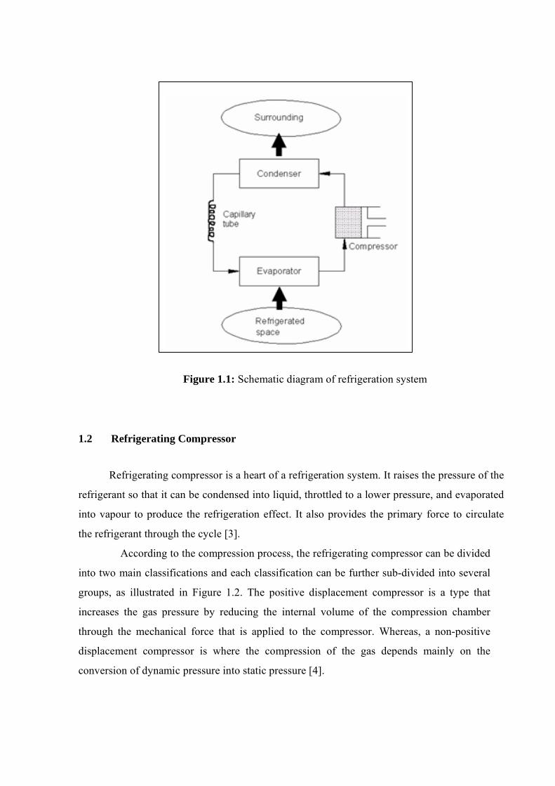
Figure 1.1: Schematic diagram of refrigeration system 1.2 Refrigerating Compressor
Refrigerating compressor is a heart of a refrigeration system. It raises the pressure of the
refrigerant so that it can be condensed into liquid, throttled to a lower pressure, and evaporated
into vapour to produce the refrigeration effect. It also provides the primary force to circulate
the refrigerant through the cycle [3].
According to the compression process, the refrigerating compressor can be divided
into two main classifications and each classification can be further sub-divided into several
groups, as illustrated in Figure 1.2. The positive displacement compressor is a type that
increases the gas pressure by reducing the internal volume of the compression chamber
through the mechanical force that is applied to the compressor. Whereas, a non-positive
displacement compressor is where the compression of the gas depends mainly on the
conversion of dynamic pressure into static pressure [4].
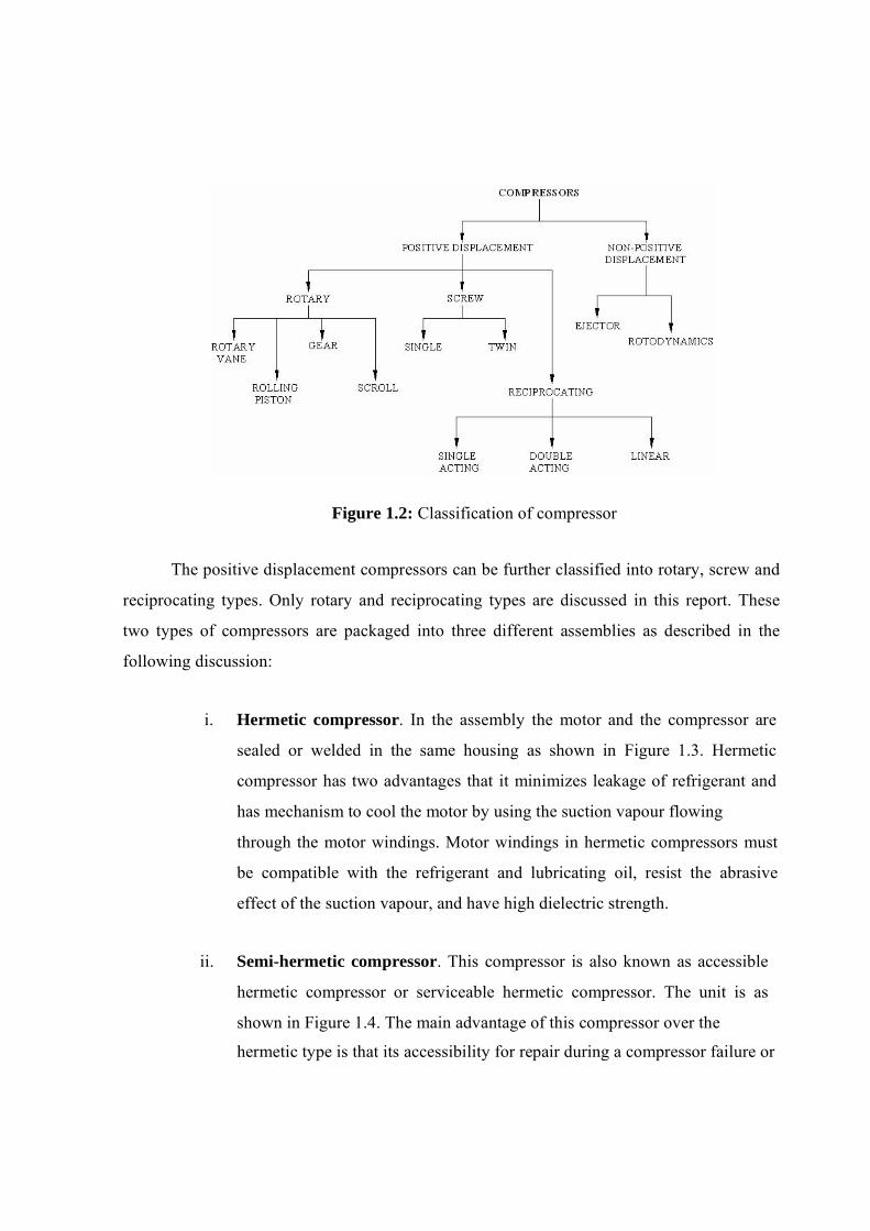
Figure 1.2: Classification of compressor
The positive displacement compressors can be further classified into rotary, screw and
reciprocating types. Only rotary and reciprocating types are discussed in this report. These
two types of compressors are packaged into three different assemblies as described in the
following discussion:
i. Hermetic compressor. In the assembly the motor and the compressor are
sealed or welded in the same housing as shown in Figure 1.3. Hermetic
compressor has two advantages that it minimizes leakage of refrigerant and
has mechanism to cool the motor by using the suction vapour flowing
through the motor windings. Motor windings in hermetic compressors must
be compatible with the refrigerant and lubricating oil, resist the abrasive
effect of the suction vapour, and have high dielectric strength.
ii. Semi-hermetic compressor. This compressor is also known as accessible
hermetic compressor or serviceable hermetic compressor. The unit is as
shown in Figure 1.4. The main advantage of this compressor over the
hermetic type is that its accessibility for repair during a compressor failure or
for regular maintenance.
iii. Open compressor. In an open compressor, the compressor and the motor are
enclosed in two separate housing as shown in Figure 1.5. This compressor
needs the shaft seals to prevent refrigerant leakage. In most cases, an enclosed
fan is used to cool the motor windings using ambient air. Notice that, there are
two driving concept of the open compressor; belting drive and direct drive. An
open compressor may be disassembled for service and preventive maintenance
to the internal parts [3, 4, 5, 6].
A- Motor rotor B- Motor stator C- Cylinder D- Piston E- Connecting rod F- Crankshaft G- Crankcase H- Shell I- Electrical
connection
Figure 1.3: Photograph of hermetic reciprocating compressor (Whitman and
Johnson, 1991)
Figure 1.4: Photograph of semi-hermetic compressor (Whitman and Johnson, 1995)
(a) Complete assembly of compressor (b) Photograph of open compressor Figure 1.5: Open compressor assembly type (Langley, 1982)
1.3 Research Overview
The application of reciprocating compressor in a refrigerator and an air- conditioner is
already established. Chillers for some big building air-conditioning system are using screw
compressors, but the researches are still on-going to improve the performance. Whereas
automotive air-conditioning system are using both rotary and reciprocating types and again
research in this area is actively pursued. Domestic refrigerator has been known to use
reciprocating compressor until lately when rotary compressor has been introduced and appears
to be successful. This success is as a result of continuous research carried out by the industry to
improve the efficiency
and reliability of rotary compressors. As described later this compressor can be of static or
rotating vane types.
The literature study has been done on the rotary and reciprocating compressors and
findings showed that the performance of rotary compressor is better than reciprocating
compressor. Recently, Universiti Technologi Malaysia (UTM) has developed a new
compression concept comprises of a rotating vane, a rotating sleeve and a rotor. This is a
simple concept compared to the other rotary compressors available in the market today. Details
of the new rotary compressor concept are shown in Figure 1.6.
Figure 1.6: Concept of single vane rotating sleeve rotary compressor
The concept is equipped with main components such as a vane, a sleeve, a rotor, a
shaft and a cylinder block. The sleeve as well as the cylinder block are assembled
eccentrically to the rotor to produce the compression chamber with a crescent-shaped area
formation. Then, the head or tip of the vane is assembled permanently into the slot on the
inner part of the sleeve, and the vane hub is put inside the rotor slot. There is a contact point
between rotor and sleeve to prevent the gas from leaking to the adjacent area. Therefore, the
center points of sleeve rotation and rotor are different, and when the rotor starts to rotate, the
vane will start to compress the gas. During first half of rotation, the sleeve pulls the vane out
of the slot and during the second half the vane is pushed back into the slot, in the rotor. This
concept is expected to reduce leakage through the vane tip which occurs in existing rotary
compressor.
Figure 1.7 describes the operation sequence of this concept. The sequence starts at 0º
with the compression chamber fully filled by gas and the high-pressure gas is completely
delivered at 360º. The rounded vane tip allows it to swing so that kinematically the rotating
mechanism works successfully inspire of eccentricity. The designed compressor will be
installed to the household refrigerator-freezer. Generally there are three types of household
refrigeration system, which are refrigerator unit, freezer unit and combination of refrigerator
and freezer. This research is focused on combination of refrigerator and freezer unit. The
combined unit is normally known as refrigerator [7].
Figure 1.7: Operation of single vane rotating sleeve rotary compressor concept
1.4 Problem Statement
In Malaysia, the main refrigerator-freezer manufacturer is Matsushita Group of
Companies with their products of National and Panasonic brands. Beside that, these companies
also produce the compressor to be supplied to other refrigerator-freezer manufacturers such as
Sanyo, Hitachi and Pensonic. Most of the refrigerator- freezers use reciprocating type
compressor. However, there is also rotary type used in refrigerator-freezer such as for three
doors refrigerator-freezer model. The presence of these companies in Malaysia gives us the
opportunity to learn the technology and the manufacturing processes involved. This will
gradually increase our capability in this industry and ensures that Malaysia remains the world
biggest supplier of domestic refrigerators and split-unit air-conditioners. In this respect
compressor is the most important component. Therefore, the main objective of this research is
to develop our own technology of compressor. The research work is focus on the weaknesses
of the two existing compressor models; rolling piston and sliding vane rotary compressor. As a
result, a superior version of compressor will come out. The weaknesses on the existing
compressors are leakage and friction problem through the vanes tip and cylinder block or
rolling piston during compression process which will be discussed later. 1.5 Significant of Research
The sliding vane rotary compressor has a fairly high volumetric efficiency. The
rolling piston rotary compressor has even higher efficiency. However from the literature
review and theoretical analysis conducted the performance of rotary compressor can be
further improved and manufacturing cost reduced. This is indeed a good starting and to
proceed to a more interesting and useful R&D work in the effort to fully acquire this very
important technology. 1.6 Objective of Research
The main objective of this study is to design and develop a rotary compressor based
on a new concept, which is a single vane rotating sleeve rotary compressor for refrigerator
application. 1.7 Scope of Research The scopes of this research are described as follow:
1) Literature study
This involves patent study, technical review and reverse engineering work.
The outcome from this study will be adopted into the new compressor
design.

2) Concept and design development Design a new rotary compressor based on the rotating vane and sleeve
concept.
CHAPTER 2
DESCRIPTIONS AND REVIEWS OF REFRIGERANT COMPRESSORS 2.1 Introduction
This chapter discusses relevant reports on the description of various concepts of rotary
compressors and a description on the concept of reciprocating compressor that is installed in
domestic refrigerators. Reviews are made on the continuous development of the rotary
compressors from the documents of the relevant patents and technical reports available in the
literature. Finally the chapter reports on the result of the reverse engineering work carried out on
the existing rotary and reciprocating compressor models. 2.2 Descriptions of Compressors 2.2.1 Rotary Compressor
Rotary compressor is a machine which compresses the gas as a result of the angular
movement of the vane or roller. Rotary compressors are normally suitable for application of low
compression ratios and for small and medium gas flowrates. Rotary compressors have certain
advantages such as continuously flow process, high speed of rotation and the design can be
scaled down to a vary small dimension. The design of this compressor does not require suction
valve and installation of discharge valve is optional. No clearance volume is required. Rotary
compressor, on the other hand, has well known disadvantages that each of them requires high
precision in machining, correct tolerance to balance between internal leakage and friction and
requires continuous cooling to prevent from mechanical jamming [8].
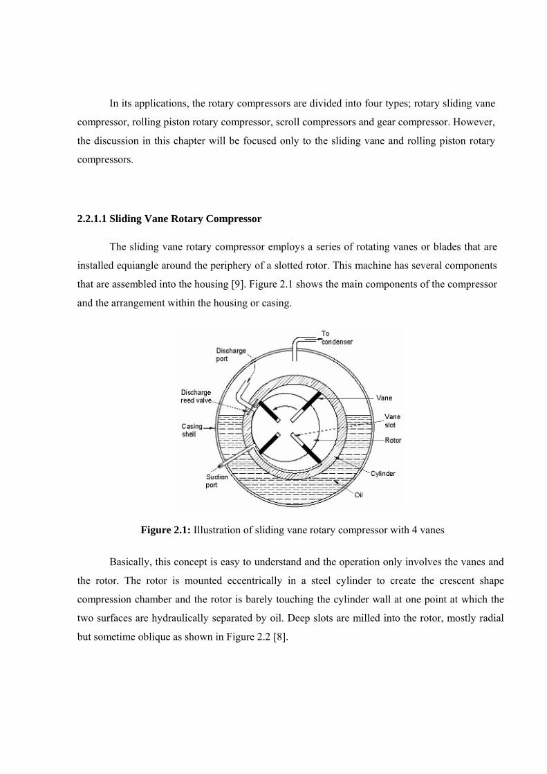
In its applications, the rotary compressors are divided into four types; rotary sliding vane
compressor, rolling piston rotary compressor, scroll compressors and gear compressor. However,
the discussion in this chapter will be focused only to the sliding vane and rolling piston rotary
compressors. 2.2.1.1 Sliding Vane Rotary Compressor
The sliding vane rotary compressor employs a series of rotating vanes or blades that are
installed equiangle around the periphery of a slotted rotor. This machine has several components
that are assembled into the housing [9]. Figure 2.1 shows the main components of the compressor
and the arrangement within the housing or casing.
Figure 2.1: Illustration of sliding vane rotary compressor with 4 vanes
Basically, this concept is easy to understand and the operation only involves the vanes and
the rotor. The rotor is mounted eccentrically in a steel cylinder to create the crescent shape
compression chamber and the rotor is barely touching the cylinder wall at one point at which the
two surfaces are hydraulically separated by oil. Deep slots are milled into the rotor, mostly radial
but sometime oblique as shown in Figure 2.2 [8].
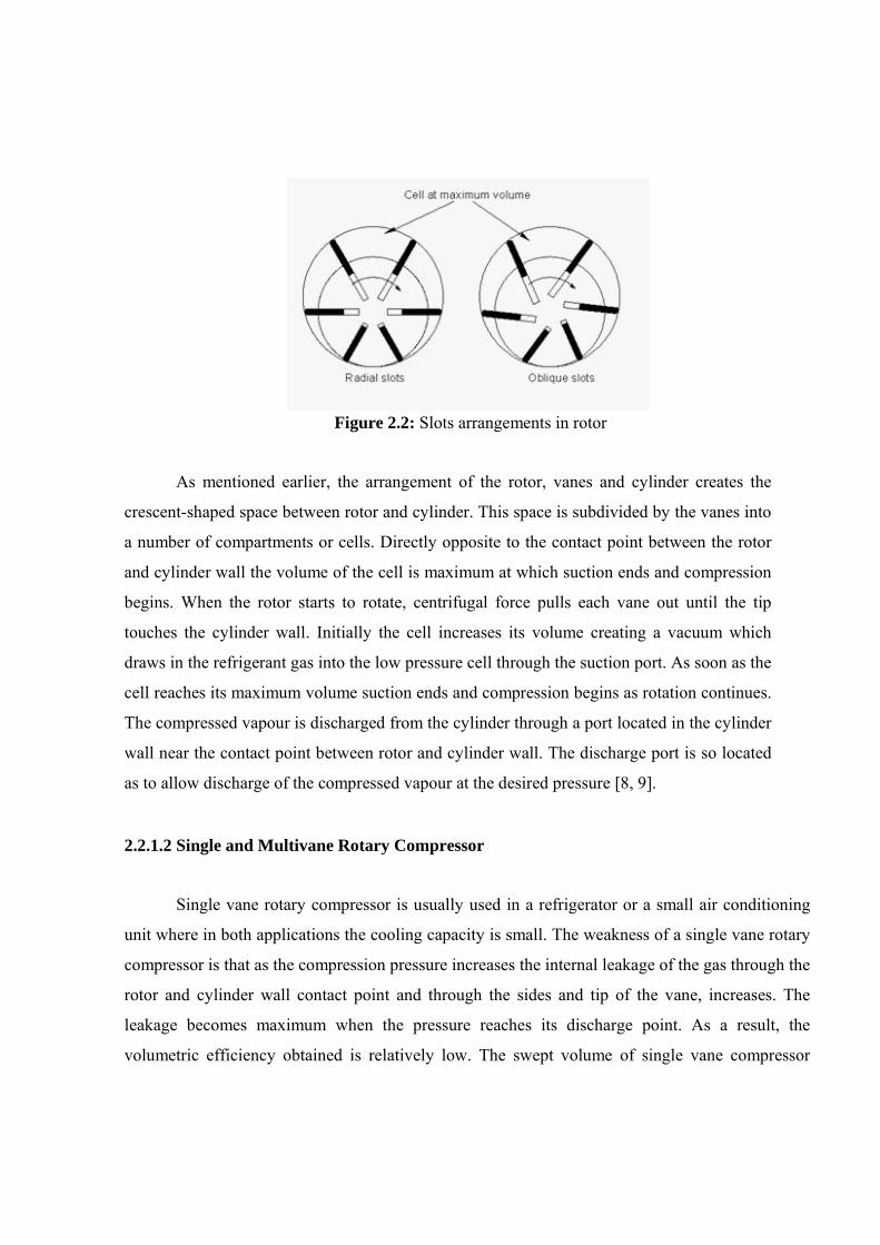
Figure 2.2: Slots arrangements in rotor
As mentioned earlier, the arrangement of the rotor, vanes and cylinder creates the
crescent-shaped space between rotor and cylinder. This space is subdivided by the vanes into
a number of compartments or cells. Directly opposite to the contact point between the rotor
and cylinder wall the volume of the cell is maximum at which suction ends and compression
begins. When the rotor starts to rotate, centrifugal force pulls each vane out until the tip
touches the cylinder wall. Initially the cell increases its volume creating a vacuum which
draws in the refrigerant gas into the low pressure cell through the suction port. As soon as the
cell reaches its maximum volume suction ends and compression begins as rotation continues.
The compressed vapour is discharged from the cylinder through a port located in the cylinder
wall near the contact point between rotor and cylinder wall. The discharge port is so located
as to allow discharge of the compressed vapour at the desired pressure [8, 9]. 2.2.1.2 Single and Multivane Rotary Compressor
Single vane rotary compressor is usually used in a refrigerator or a small air conditioning
unit where in both applications the cooling capacity is small. The weakness of a single vane rotary
compressor is that as the compression pressure increases the internal leakage of the gas through the
rotor and cylinder wall contact point and through the sides and tip of the vane, increases. The
leakage becomes maximum when the pressure reaches its discharge point. As a result, the
volumetric efficiency obtained is relatively low. The swept volume of single vane compressor
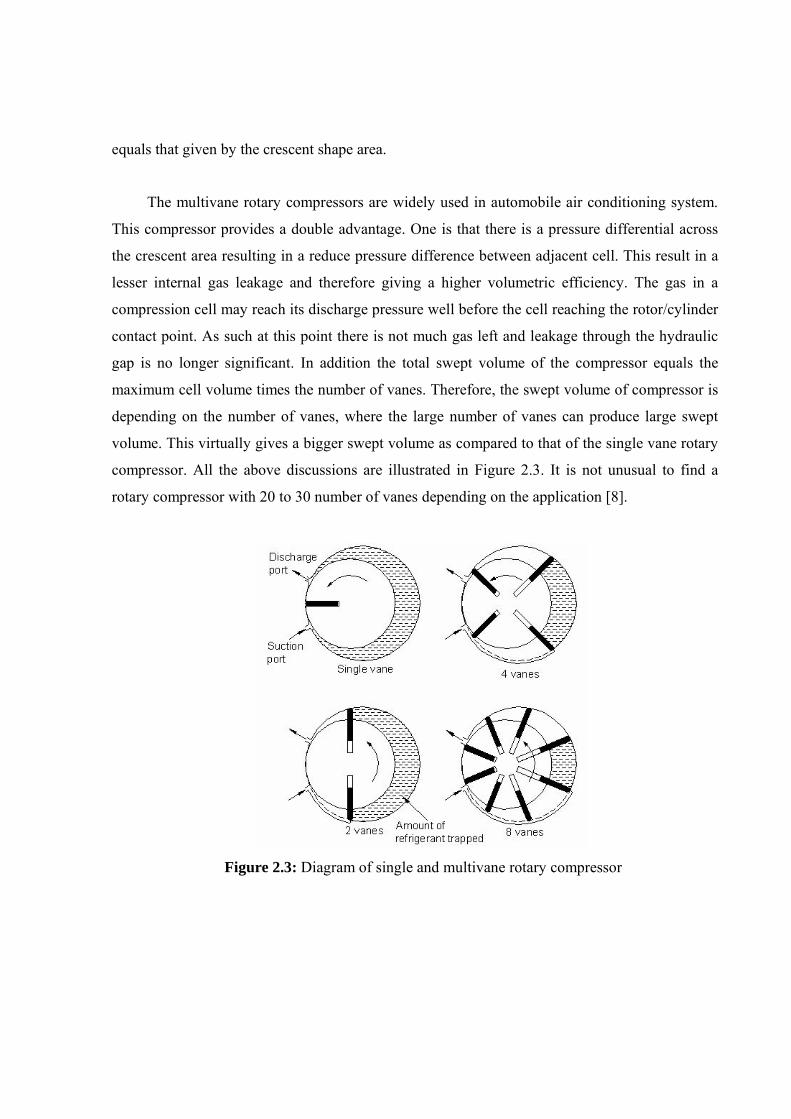
equals that given by the crescent shape area.
The multivane rotary compressors are widely used in automobile air conditioning system.
This compressor provides a double advantage. One is that there is a pressure differential across
the crescent area resulting in a reduce pressure difference between adjacent cell. This result in a
lesser internal gas leakage and therefore giving a higher volumetric efficiency. The gas in a
compression cell may reach its discharge pressure well before the cell reaching the rotor/cylinder
contact point. As such at this point there is not much gas left and leakage through the hydraulic
gap is no longer significant. In addition the total swept volume of the compressor equals the
maximum cell volume times the number of vanes. Therefore, the swept volume of compressor is
depending on the number of vanes, where the large number of vanes can produce large swept
volume. This virtually gives a bigger swept volume as compared to that of the single vane rotary
compressor. All the above discussions are illustrated in Figure 2.3. It is not unusual to find a
rotary compressor with 20 to 30 number of vanes depending on the application [8].
Figure 2.3: Diagram of single and multivane rotary compressor
2.2.1.3 Rolling Piston Rotary Compressor
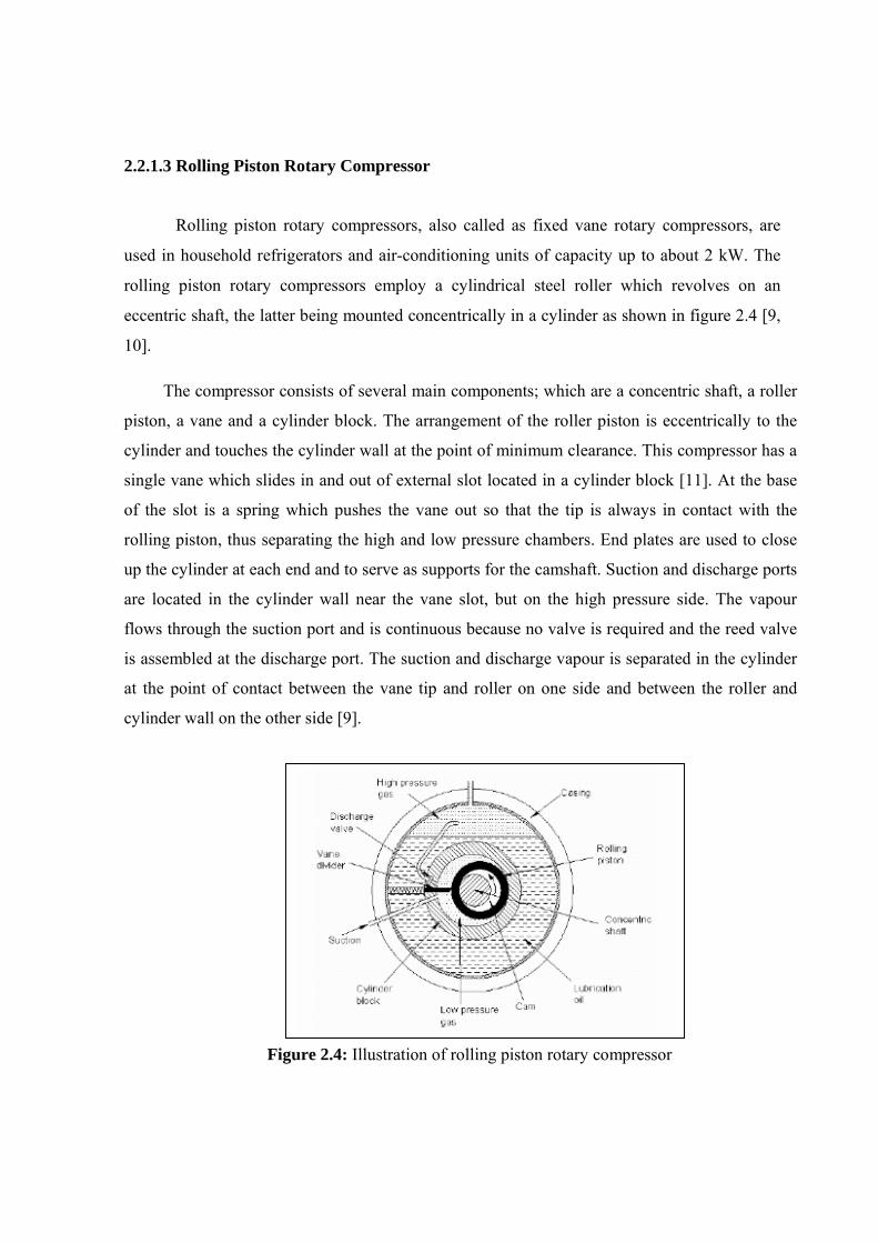
Rolling piston rotary compressors, also called as fixed vane rotary compressors, are
used in household refrigerators and air-conditioning units of capacity up to about 2 kW. The
rolling piston rotary compressors employ a cylindrical steel roller which revolves on an
eccentric shaft, the latter being mounted concentrically in a cylinder as shown in figure 2.4 [9,
10].
The compressor consists of several main components; which are a concentric shaft, a roller
piston, a vane and a cylinder block. The arrangement of the roller piston is eccentrically to the
cylinder and touches the cylinder wall at the point of minimum clearance. This compressor has a
single vane which slides in and out of external slot located in a cylinder block [11]. At the base
of the slot is a spring which pushes the vane out so that the tip is always in contact with the
rolling piston, thus separating the high and low pressure chambers. End plates are used to close
up the cylinder at each end and to serve as supports for the camshaft. Suction and discharge ports
are located in the cylinder wall near the vane slot, but on the high pressure side. The vapour
flows through the suction port and is continuous because no valve is required and the reed valve
is assembled at the discharge port. The suction and discharge vapour is separated in the cylinder
at the point of contact between the vane tip and roller on one side and between the roller and
cylinder wall on the other side [9].
Figure 2.4: Illustration of rolling piston rotary compressor

The sequence of the compressor operation is illustrated in Figure 2.5 [12]. Initially, the
vapour is induced through a suction port to fill the compression chamber which is closed by a
vane and the contact line such as illustrated in Figure 2.5(a). As the shaft starts to rotate, the
rolling piston rolls around the cylinder wall in the direction of shaft rotation and always in
contact with the cylinder wall. When the rotor has rolled over the suction port, the vapour in the
cylinder is steadily compressed. The discharge process will occur when the compressed vapour
is slightly higher than that of the vapour at outside of compression chamber resulting the
discharge valve to open and the compressed vapor will be pushed out to the discharge line.
Figure 2.5: Operation principle of rolling piston rotary compressor
The rolling piston rotary compressors have a very small clearance volume same as sliding
vane compressors. As a result, these compressors can produce higher volumetric efficiency
compared to that produced by a reciprocating compressor. The volumetric efficiency also
depends on the internal leakages during compression. The internal leakages can be minimized
through hydrodynamic sealing, mating parts selection and clearances application. The
hydrodynamic sealing is created by an oil film formation on a pair of rubbing surfaces and
depends on clearance, surface speed, surface finish and oil viscosity. The high mechanical
efficiency is achieved by minimizing friction losses that occur between the vane and slot wall,
vane tip and roller and between cam, roller and end plates. The rolling piston compressor also
produces less noise and vibration as a result of the installation of weights that counter-balance
the rolling piston during the operation [9]. 2.2.2 Reciprocating Compressor
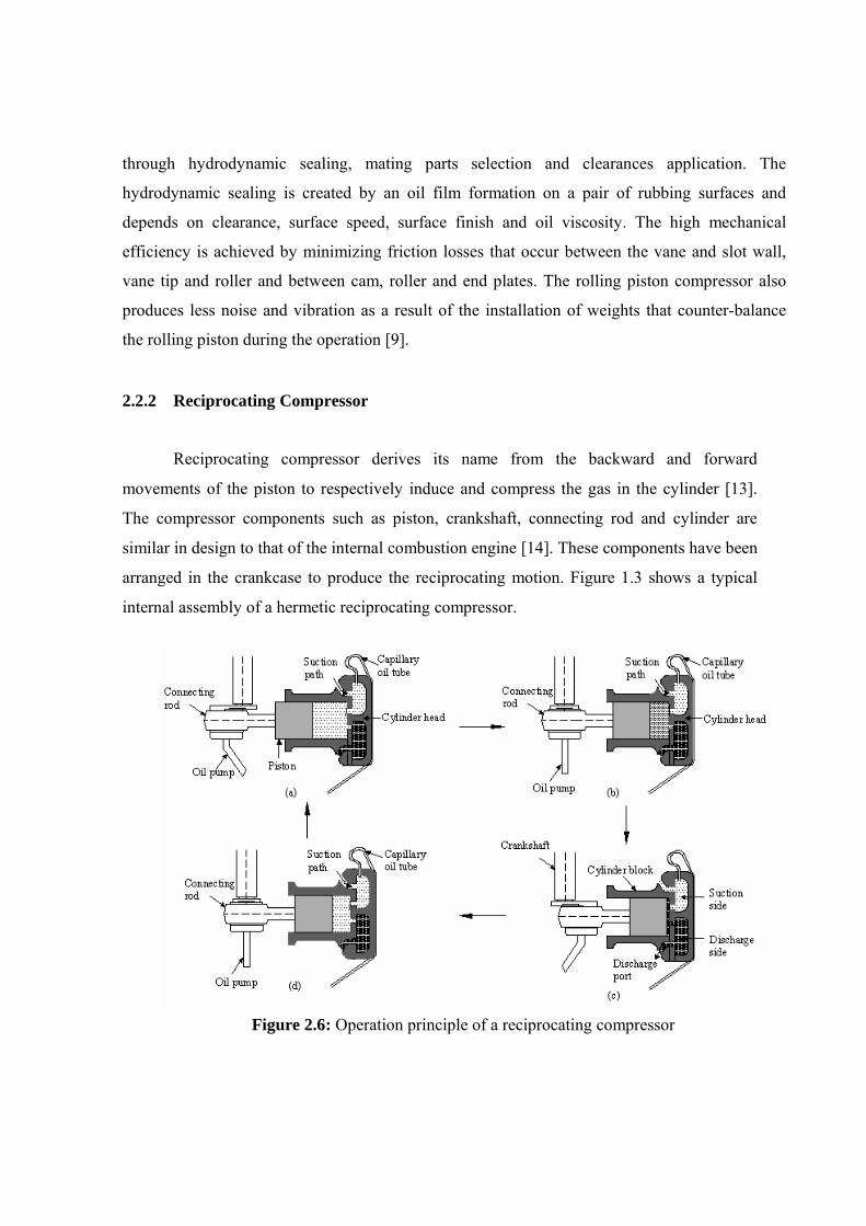
Reciprocating compressor derives its name from the backward and forward
movements of the piston to respectively induce and compress the gas in the cylinder [13].
The compressor components such as piston, crankshaft, connecting rod and cylinder are
similar in design to that of the internal combustion engine [14]. These components have been
arranged in the crankcase to produce the reciprocating motion. Figure 1.3 shows a typical
internal assembly of a hermetic reciprocating compressor.
Figure 2.6: Operation principle of a reciprocating compressor
Figure 2.6 shows the operating principle of the reciprocating compressor. As the piston
moves downward (or to the left) a vacuum is created and the suction valve opens and low
pressure refrigerant vapour from evaporator fills up the cylinder until the piston reaches the
bottom dead center (BDC) as shown in Figure 2.6 (a). Figure 2.6 (b) shows the compression
stroke. At first both suction and discharge valves are closed as the pressure increases and
volume decreases. At pressure which is slightly higher than that of the condenser the
discharge valve opens and the gas is released and flows into the condenser as shown in Figure
2.6 (c). To allow movement of suction valve the piston stops at the top dead center creating
the space called a clearance volume which is occupied by the residual high pressure gas. The
residue will expand and mix with fresh gas during suction stroke to complete the cycle as
shown in Figure 2.6 (d) [15, 16]. 2.3 Reviews
Compressors of sliding single or multi-vane, single vane rolling piston and finally of
reciprocating types have been respectively described. These three types are that normally used
for low thermal load application like in a domestic refrigerator, in a small split unit room air
conditioner or in a small automotive air-conditioning system. These types are further studied
by reviewing:
i) The relevant patents,
ii) The literature on technical papers from proceedings and journals, and
iii) The designs of existing models that are available in the market. 2.3.1 Patents Review
There are thousand of patents on compressor in US patent file alone. This file is dated as
early as 1873. However, there are probably about half are on rotary types which were filed as early
as 1911 followed by innovative improvement efforts showing a trend that it will continue into the
21st century. The reciprocating type is an old and already established technology and lately very
few and minor innovative efforts are filed and successfully patented. As such the patent review
carried out in this work is focused only on rolling piston and sliding vane rotary compressor types. 2.3.1.1 Patent of Rolling Piston Rotary Compressor
The rolling piston concept was introduced earlier in 1911 by Kinney, J. R. [17] who
developed the rotary pump. In 1933, Buchanan, J. C. and Hubacker, E. F. [18] introduced an
improvement in the discharge system by using a flapper valve. Warrick, L. K. et al. [19]
improved the rolling piston concept design for refrigeration compressor. They developed the
seal housing assembly method for compressor and motor, and improved the lubrication
arrangement mechanism. Since the compressor was introduced in last several decades, there are
several modifications in design to increase volumetric efficiency, reduce noise, improve
balancing, improve sealing and etc.
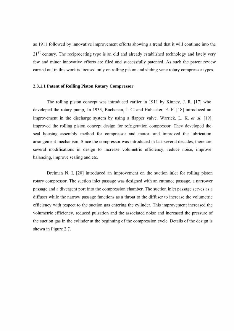
Dreiman N. I. [20] introduced an improvement on the suction inlet for rolling piston
rotary compressor. The suction inlet passage was designed with an entrance passage, a narrower
passage and a divergent port into the compression chamber. The suction inlet passage serves as a
diffuser while the narrow passage functions as a throat to the diffuser to increase the volumetric
efficiency with respect to the suction gas entering the cylinder. This improvement increased the
volumetric efficiency, reduced pulsation and the associated noise and increased the pressure of
the suction gas in the cylinder at the beginning of the compression cycle. Details of the design is
shown in Figure 2.7.
Innovation by Dreiman Prior design
Figure 2.7: Innovation of suction inlet rolling piston rotary compressor by Dreiman, N. I
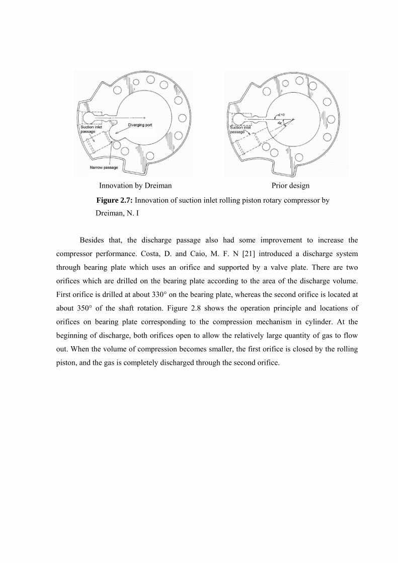
Besides that, the discharge passage also had some improvement to increase the
compressor performance. Costa, D. and Caio, M. F. N [21] introduced a discharge system
through bearing plate which uses an orifice and supported by a valve plate. There are two
orifices which are drilled on the bearing plate according to the area of the discharge volume.
First orifice is drilled at about 330° on the bearing plate, whereas the second orifice is located at
about 350° of the shaft rotation. Figure 2.8 shows the operation principle and locations of
orifices on bearing plate corresponding to the compression mechanism in cylinder. At the
beginning of discharge, both orifices open to allow the relatively large quantity of gas to flow
out. When the volume of compression becomes smaller, the first orifice is closed by the rolling
piston, and the gas is completely discharged through the second orifice.
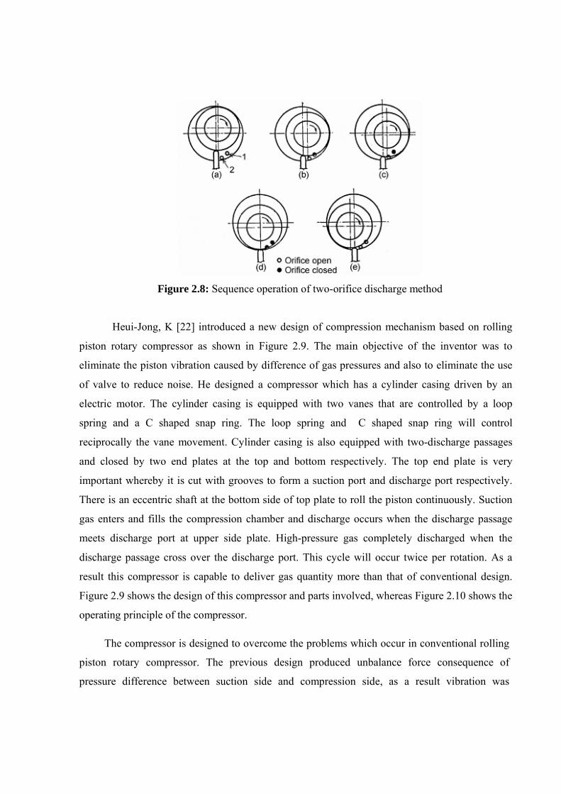
Figure 2.8: Sequence operation of two-orifice discharge method
Heui-Jong, K [22] introduced a new design of compression mechanism based on rolling
piston rotary compressor as shown in Figure 2.9. The main objective of the inventor was to
eliminate the piston vibration caused by difference of gas pressures and also to eliminate the use
of valve to reduce noise. He designed a compressor which has a cylinder casing driven by an
electric motor. The cylinder casing is equipped with two vanes that are controlled by a loop
spring and a C shaped snap ring. The loop spring and C shaped snap ring will control
reciprocally the vane movement. Cylinder casing is also equipped with two-discharge passages
and closed by two end plates at the top and bottom respectively. The top end plate is very
important whereby it is cut with grooves to form a suction port and discharge port respectively.
There is an eccentric shaft at the bottom side of top plate to roll the piston continuously. Suction
gas enters and fills the compression chamber and discharge occurs when the discharge passage
meets discharge port at upper side plate. High-pressure gas completely discharged when the
discharge passage cross over the discharge port. This cycle will occur twice per rotation. As a
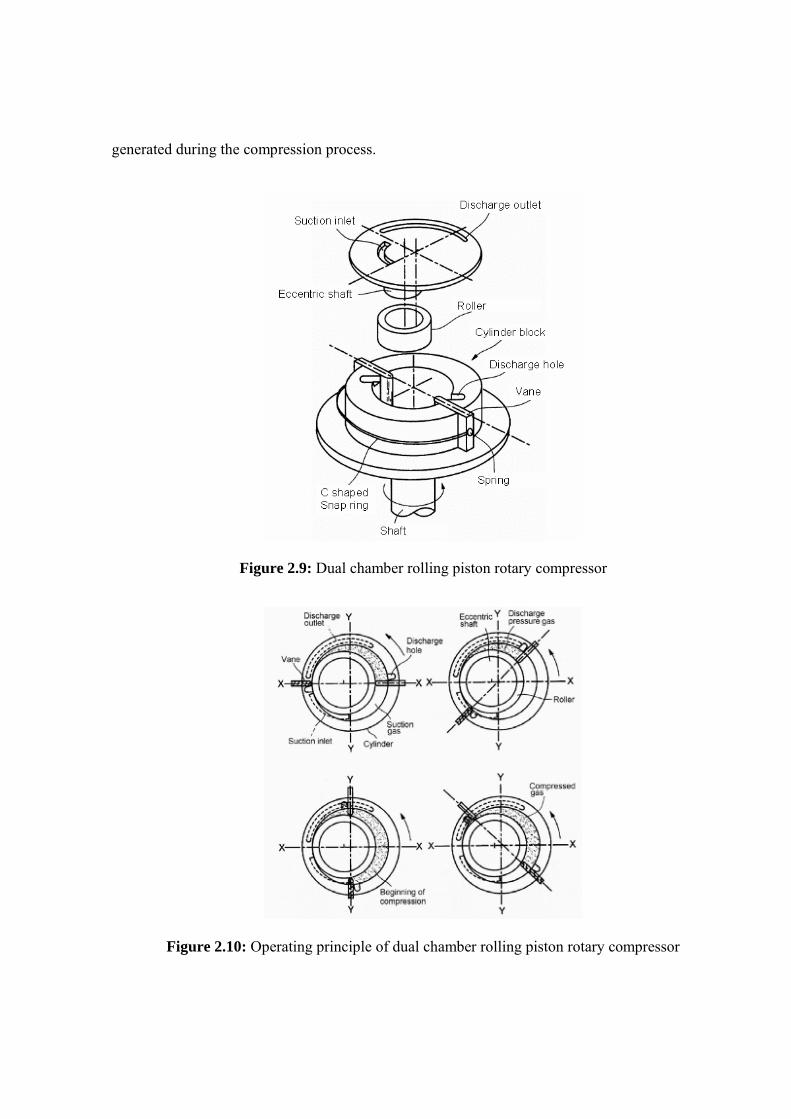
result this compressor is capable to deliver gas quantity more than that of conventional design.
Figure 2.9 shows the design of this compressor and parts involved, whereas Figure 2.10 shows the
operating principle of the compressor.
The compressor is designed to overcome the problems which occur in conventional rolling
piston rotary compressor. The previous design produced unbalance force consequence of
pressure difference between suction side and compression side, as a result vibration was
generated during the compression process.
Figure 2.9: Dual chamber rolling piston rotary compressor
Figure 2.10: Operating principle of dual chamber rolling piston rotary compressor
2.3.1.2 Patent of Sliding Vane Rotary Compressor
The basic idea of sliding multi-vane rotary compressor design began with a single-vane
concept. Since then, the improvement has been made to increase the gas quantity delivered,
efficiency and performance of compressor by increasing the vane numbers and modifying the
compression chamber shaped. Previously, Gillespie, J. E [23] introduced a single vane rotary
pump with eccentric ring. The advantage of this pump is having two compression chambers.
One chamber between rotor and eccentric ring, and other one is between eccentric ring and
outer cylinder. Walter, J. P [24] introduced the multi-vane rotary pump for water. Camilo, V.
N [25] introduced rotary vacuum and compressor pump. In this invention, he reduced frictional
losses and wear, and also reduced contact pressure between vane tip and cylinder wall by
designing the vane with light material. Otherwise, Adalbert, G., et al. [26] introduced a new
sliding vane compressor completed with oil sealing at clearance gaps. The oil was supplied
from the high-pressure tank of the compressor to the clearance gaps between the rotor end
faces and lateral stationary faces of the housing.
The design of a sliding vane rotary compressor was further improved by introducing two
oval shaped compression chambers. The rotor and cylinder block were assembled concentrically
and having two contact points at opposite positions of each other. The contact points divide the
cylinder bore into the two crescent-shaped spaces. The operating principle of this compressor is
similar to that with a single chamber sliding vane rotary compressor. Adalbert, G and Vysiotis
[27] designed the dual chamber rotary sliding vane compressor for a vehicle air conditioner. The
advantages of dual chamber rotary compressor are providing more quantity gas delivered and
reducing the friction loss to one half that for a single chamber rotary sliding vane compressor.
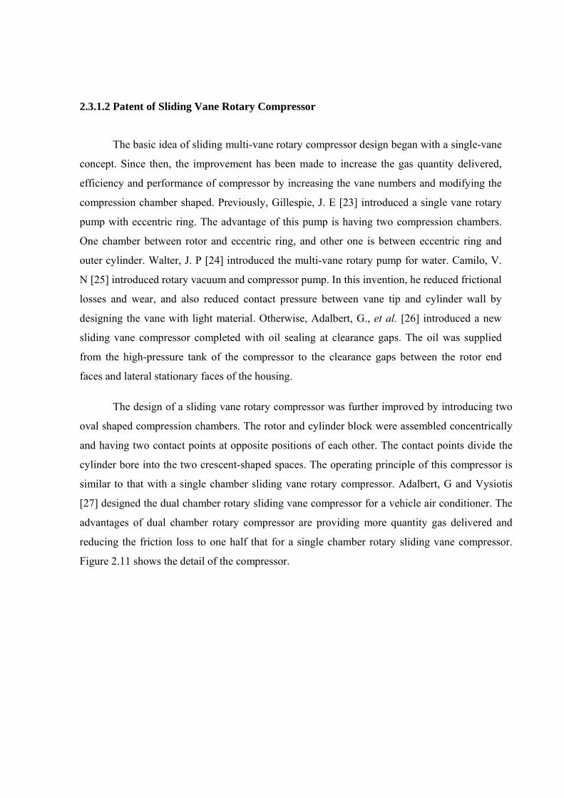
Figure 2.11 shows the detail of the compressor.
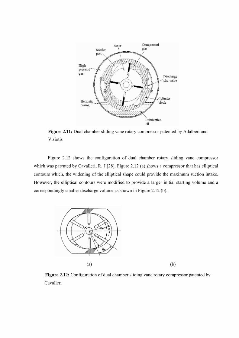
Figure 2.11: Dual chamber sliding vane rotary compressor patented by Adalbert and Visiotis
Figure 2.12 shows the configuration of dual chamber rotary sliding vane compressor
which was patented by Cavalleri, R. J [28]. Figure 2.12 (a) shows a compressor that has elliptical
contours which, the widening of the elliptical shape could provide the maximum suction intake.
However, the elliptical contours were modified to provide a larger initial starting volume and a
correspondingly smaller discharge volume as shown in Figure 2.12 (b).
(a) (b)
Figure 2.12: Configuration of dual chamber sliding vane rotary compressor patented by
Cavalleri
2.3.2 Literature Review 2.3.2.1 Design Geometry
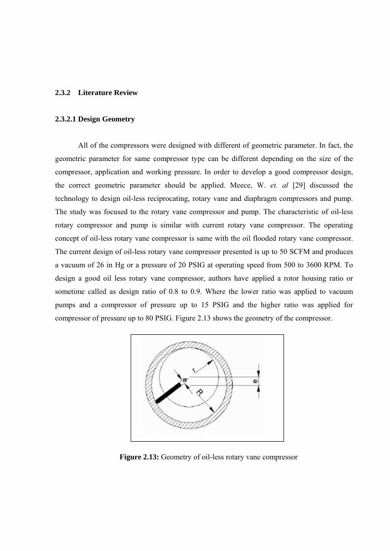
All of the compressors were designed with different of geometric parameter. In fact, the
geometric parameter for same compressor type can be different depending on the size of the
compressor, application and working pressure. In order to develop a good compressor design,
the correct geometric parameter should be applied. Meece, W. et. al [29] discussed the
technology to design oil-less reciprocating, rotary vane and diaphragm compressors and pump.
The study was focused to the rotary vane compressor and pump. The characteristic of oil-less
rotary compressor and pump is similar with current rotary vane compressor. The operating
concept of oil-less rotary vane compressor is same with the oil flooded rotary vane compressor.
The current design of oil-less rotary vane compressor presented is up to 50 SCFM and produces
a vacuum of 26 in Hg or a pressure of 20 PSIG at operating speed from 500 to 3600 RPM. To
design a good oil less rotary vane compressor, authors have applied a rotor housing ratio or
sometime called as design ratio of 0.8 to 0.9. Where the lower ratio was applied to vacuum
pumps and a compressor of pressure up to 15 PSIG and the higher ratio was applied for
compressor of pressure up to 80 PSIG. Figure 2.13 shows the geometry of the compressor.
Figure 2.13: Geometry of oil-less rotary vane compressor
2.3.2.2 Performance
Performance of a rotary compressor depends on the control of key clearances between the
respective moving parts. The gaps in these key clearances should receive adequate lubricantion
oil to reduce friction, wear and leakage. The effect of leakage in a rotary compressor is to reduce
the delivered flow of refrigerant, reducing the cooling capacity and volumetric efficiency, and
increasing the compression power. Pandeya, P. and Soedel, W. [30] identified the various losses
in a hermetic type rolling piston rotary compressor. These losses are divided into two broad
categories; the energy losses and the mass flow losses. The energy losses involving motor loss,
friction loss, compression loss, valve loss and lubricant pump loss. Whereas, the mass flow
losses involving clearance volume loss, leakage loss, back-flow loss, suction-gas heating loss
and loss due to lubricant flow. This paper only discusses two types of losses that occur due to
friction in the cylinder and that due to leakage. In the investigation, there are 6 points of friction
losses in cylinder and 4 points of leakage losses have been identified. They developed
mathematical model for each losses point. As a result, the predicted ideal mass flow of this
compressor is 8.84 kg/hr with the leakage loss of approximately 12% and cylinder friction loss
approximately 9%. T. Matsuzaka and S. Nagatomo [31] discussed the performance analysis of
rolling piston rotary compressor. They analyzed the losses factors that affect the compressor
efficiency theoretically and experimentally. They optimized the discharge port shape
corresponds to maximum compressor efficiency. As a result, the volumetric efficiency was
increased to 94% and compression efficiency to 96%. Besides that, they have also improved the
mechanical losses by considering the lubrication, reliability and vibration. As a result, they have
increased the mechanical efficiency to 94%. Through this method, they found that the maximum
compressor efficiency was 74%. H. Kawai [32] introduced a high efficiency horizontal rolling
piston rotary compressor for household refrigerators. An experimental analysis was done to
determine the performance characteristics of the compressor looking at three things:
1) Assumption of excessive compression loss by making the entire discharge system
as one orifice. 2) Determination of a clearance between the blade and piston.
3) Efficiency improvement and noise reduction through design improvement of the bearing.
It was found that, an excessive compression in the compressor occurred due to the small
size of discharge port designed. This was discovered after it was analyzed by simulating the
discharge system as an orifice model. The consideration also made to the effective flow area of
discharge port and experimental simulation was done to the various discharge port sizes to
optimize the design of the discharge system. As a result, 3 to 4 % of efficiency improvement was
realized. S. Nagatomo et al. [33] discussed the performance analysis in a rolling piston type
hermetic compressor that was used in domestic refrigerators. They analyzed the two main
influencing factors on the compressor efficiency. Those are roller clearance and the discharge
port length. In order to measure the performance of the compressor, the test model was
developed by assembling three units of Piezo type pressure transducer at locations of �� 31�,
� �230� and �� 353�. An eddy current probe was mounted on the center of the valve stopper
to measure the discharge valve behavior. The roller clearance was varied and when the roller
clearance was large, the volumetric efficiency was reduced and compressor intake power
increased. This was caused by the oil leakage to the suction side of the cylinder from the inside
of the roller through the axial clearance. Four kinds of discharge port lengths were used in this
experiment. The length of discharge port influences compressor efficiency by means of re-
expansion of the residual gas in the discharge port. If the discharge port length becomes large,
the quantity of residual gas in the cylinder increased resulting in a decrease in compression
efficiency. Result from the analysis of the various sizes of roller clearance and discharge port
lengths show that the isentropic work improves from 48.2 % to 55.2 %. T. Nomura et al. [34]
discussed the method to improve the efficiency of rolling piston rotary compressor. They also
carried out an investigation to identify power losses in previous rotary compressors. It was
founded that the overall efficiency is about 57.2 % and the largest power losses are the motor
loss that accounts for about one half of the total power loss. From the losses analysis, the
counter-measures were planned for reducing those losses. The conformation tests on the
effectiveness of these measures were also conducted, than the counter-measures that have the
large effect to the performance improvement were selected and were applied to real machine. As
a result, the overall efficiency was increased by about 12 %. H. Shintaku et al. [35] introduced a
swing piston type compressor based on rolling piston rotary compressor. The designed
compressor has reduced the sliding loss and contact pressure between roller and vane tip. The
compressor was designed with a groove machined on the outer surface of the conventional
rolling piston so that the vane tip can be entered into the grove. The differences in operation of
this compressor compared with the conventional rolling piston are; (1) the swing movement of
the piston and (2) the swinging piston structure has a groove with a cross section of a circular arc
and a radius almost same as the vane tip radius. This is to provide swinging motion and to secure
the contact area between vane tip and piston so that it can reduce the contact pressure and
improve the sealing performance. The feasibility of this compressor was examined both
theoretically and experimentally. As a result, the mechanical efficiency is increased about 1 %
and COP about 1 % based on theoretical analysis. Experimental result had shown that the
improvement in mechanical efficiency is about 1 %, COP is about 2.2 %, indicated efficiency is
about 1.1 %, the increment of volumetric efficiency is about 0.7 % and compressor efficiency is
about 2.9 %.
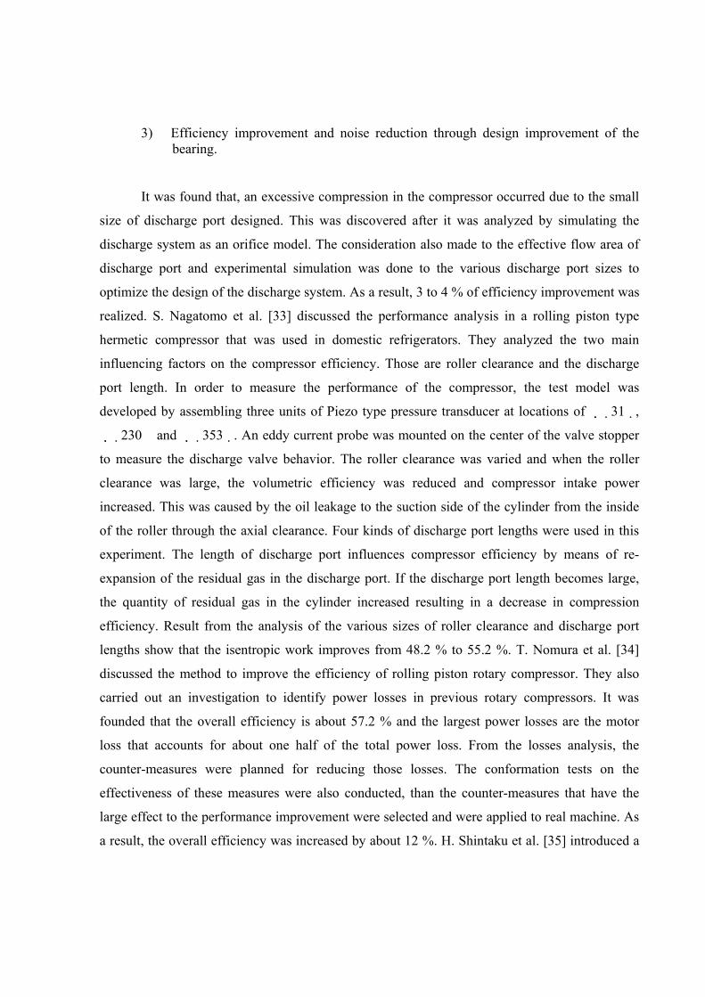
Y. Huang et al. [36] introduced a new two stage rolling piston rotary compressor design
for automotive air conditioning system. The objective is to achieve a well-balanced performance,
Noise-Vibration-Harshness (NVH), durability, variable capacity, manufacturability and cost of
operation. The compression principle of this compressor is shown in Figure 2.14. Low-pressure
refrigerant vapour is introduced into the first stage compression chamber via ports situated in the
sliding vane. First stage of compressed gas is discharged into an intermediate plenum in the rear
housing through a reed valve. Then the intermediate refrigerant gas is introduced into the second
stage chamber formed by inner wall of rotor and the outer wall of the post to complete the full
compression.
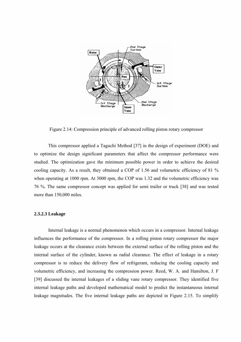
Figure 2.14: Compression principle of advanced rolling piston rotary compressor
This compressor applied a Taguchi Method [37] in the design of experiment (DOE) and
to optimize the design significant parameters that affect the compressor performance were
studied. The optimization gave the minimum possible power in order to achieve the desired
cooling capacity. As a result, they obtained a COP of 1.56 and volumetric efficiency of 81 %
when operating at 1000 rpm. At 3000 rpm, the COP was 1.32 and the volumetric efficiency was
76 %. The same compressor concept was applied for semi trailer or truck [38] and was tested
more than 150,000 miles.
2.3.2.3 Leakage
Internal leakage is a normal phenomenon which occurs in a compressor. Internal leakage
influences the performance of the compressor. In a rolling piston rotary compressor the major
leakage occurs at the clearance exists between the external surface of the rolling piston and the
internal surface of the cylinder, known as radial clearance. The effect of leakage in a rotary
compressor is to reduce the delivery flow of refrigerant, reducing the cooling capacity and
volumetric efficiency, and increasing the compression power. Reed, W. A. and Hamilton, J. F
[39] discussed the internal leakages of a sliding vane rotary compressor. They identified five
internal leakage paths and developed mathematical model to predict the instantaneous internal
leakage magnitudes. The five internal leakage paths are depicted in Figure 2.15. To simplify
analysis, the compressor is divided into three-control volumes which are a suction chamber, an
intermediate transfer chamber and a discharge chamber. In the analysis of the leakage paths
through the minimum clearance, past the blade edge, and past the blade tip, two extreme cases
have been analyzed to establish upper and lower bounds for the leakage magnitude. Upper
bounds were established by assuming the leakage fluids to be entirely compressible refrigerant
gas completely filling the clearance space. Lower bounds were established by assuming the
leakage fluids filling the clearance space to be an incompressible mixture of lubrication oil
diluted with an equilibrium concentration of refrigerant gas. Figure 2.16 summarizes the analysis
of the individual internal leakage magnitudes by rating the various leakages. The most significant
internal leakages were found occurs through the lubricating oil system (iv) and through the
minimum clearance
(i). Secondary leakages are past the blade edges
(ii) and from the discharge valve transfer slot
(iii). Leakage past the blade tip
(v) was found to be negligible.
Figure 2.15: Definition points of internal leakage paths by Reed and Hamilton
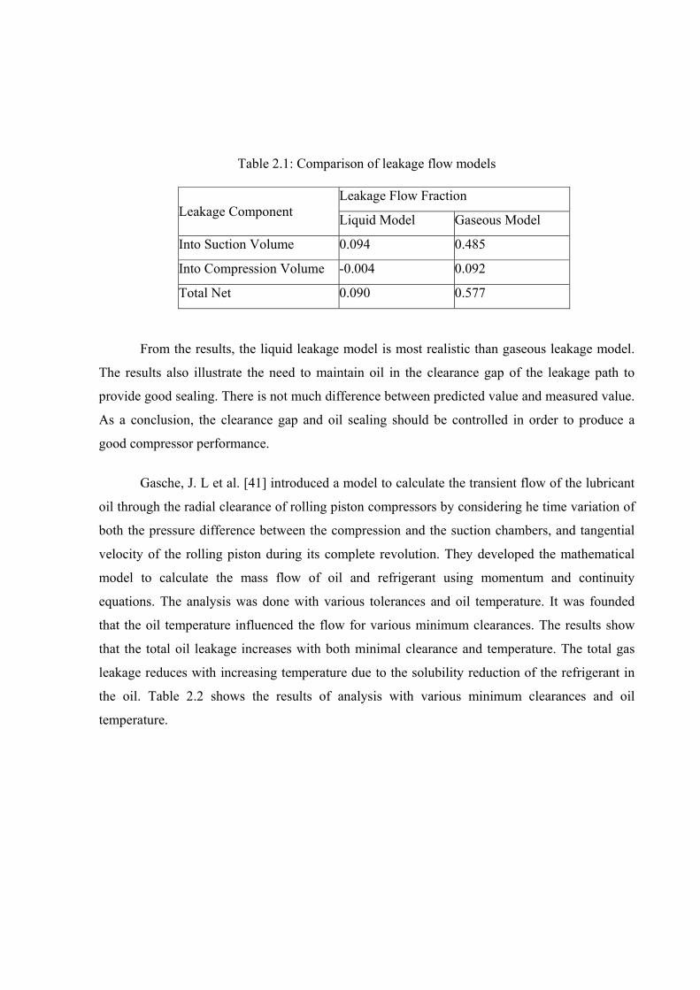
Table 2.1: Comparison of leakage flow models
Leakage Flow Fraction Leakage Component Liquid Model Gaseous Model
Into Suction Volume 0.094 0.485
Into Compression Volume -0.004 0.092
Total Net 0.090 0.577
From the results, the liquid leakage model is most realistic than gaseous leakage model.
The results also illustrate the need to maintain oil in the clearance gap of the leakage path to
provide good sealing. There is not much difference between predicted value and measured value.
As a conclusion, the clearance gap and oil sealing should be controlled in order to produce a
good compressor performance.
Gasche, J. L et al. [41] introduced a model to calculate the transient flow of the lubricant
oil through the radial clearance of rolling piston compressors by considering he time variation of
both the pressure difference between the compression and the suction chambers, and tangential
velocity of the rolling piston during its complete revolution. They developed the mathematical
model to calculate the mass flow of oil and refrigerant using momentum and continuity
equations. The analysis was done with various tolerances and oil temperature. It was founded
that the oil temperature influenced the flow for various minimum clearances. The results show
that the total oil leakage increases with both minimal clearance and temperature. The total gas
leakage reduces with increasing temperature due to the solubility reduction of the refrigerant in
the oil. Table 2.2 shows the results of analysis with various minimum clearances and oil
temperature.
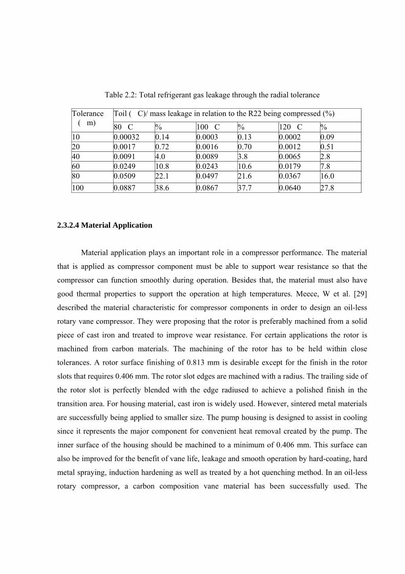
Table 2.2: Total refrigerant gas leakage through the radial tolerance
Toil (�C)/ mass leakage in relation to the R22 being compressed (%) Tolerance �(�m) 80�C % 100�C % 120�C % 10 0.00032 0.14 0.0003 0.13 0.0002 0.09 20 0.0017 0.72 0.0016 0.70 0.0012 0.51 40 0.0091 4.0 0.0089 3.8 0.0065 2.8 60 0.0249 10.8 0.0243 10.6 0.0179 7.8 80 0.0509 22.1 0.0497 21.6 0.0367 16.0 100 0.0887 38.6 0.0867 37.7 0.0640 27.8
2.3.2.4 Material Application
Material application plays an important role in a compressor performance. The material
that is applied as compressor component must be able to support wear resistance so that the
compressor can function smoothly during operation. Besides that, the material must also have
good thermal properties to support the operation at high temperatures. Meece, W et al. [29]
described the material characteristic for compressor components in order to design an oil-less
rotary vane compressor. They were proposing that the rotor is preferably machined from a solid
piece of cast iron and treated to improve wear resistance. For certain applications the rotor is
machined from carbon materials. The machining of the rotor has to be held within close
tolerances. A rotor surface finishing of 0.813 mm is desirable except for the finish in the rotor
slots that requires 0.406 mm. The rotor slot edges are machined with a radius. The trailing side of
the rotor slot is perfectly blended with the edge radiused to achieve a polished finish in the
transition area. For housing material, cast iron is widely used. However, sintered metal materials
are successfully being applied to smaller size. The pump housing is designed to assist in cooling
since it represents the major component for convenient heat removal created by the pump. The
inner surface of the housing should be machined to a minimum of 0.406 mm. This surface can
also be improved for the benefit of vane life, leakage and smooth operation by hard-coating, hard
metal spraying, induction hardening as well as treated by a hot quenching method. In an oil-less
rotary compressor, a carbon composition vane material has been successfully used. The
outstanding advantages of carbon vanes over other materials are the self-lubricant properties and
low specific gravity. The low expansion rate of carbon material contributes to dimensional
stability, which is a remarkable advantage. The low coefficient of thermal expansion makes it
possible to maintain desired clearance between vane end plate and vane rotor slot. The vane has
to be machined to precise dimensions. Gap between vane and end plate should be 0.0127 to
0.0381 mm depending on length and vane thickness, in order to obtain minimum leakage. The
leading edge of the vane should be radiused to prevent chipping and to reduce carbon dusting.
Komatsubara, T et al. [42] studied the material selection for a rotary compressor. In their study,
they investigated the use of metal matrix composite (MMC) as a high strength and reliable
lightweight material and the use of fiber reinforced aluminium (FR- Al) alloy for moving parts.
The authors developed the fiber reinforcement Aluminium Alloys material to be used in the
compressor. There are two methods introduced by the authors to produce the FR-Al alloys;
powder metallurgical process and the squeeze casting process. New FR-Al alloys were used as
the material for the vane and rotor. As a result, it passed all the performance tests on durability,
light weight, excellent wear resistance, high strength and high chemical stability.
2.3.3 Design Review
In this section the review were carried out on existing models of reciprocating
compressor, rolling piston rotary compressor and rotary sliding vane compressor. Reciprocating
compressor is relevant because it is used in existing refrigerator models and a direct comparison
on performance can be made with the proposed rotary compressor. The rolling piston rotary
compressor and a rotary sliding vane compressor are used as a design reference.
2.3.3.1 Reciprocating Compressor Design Review
The refrigerator that was used in the study as the experimental rig has the reciprocating
compressor with the following information or specification:
Manufacturer : Matsushita Compressor (M). Model : DA66C12RAY5
Refrigerant Charge : 160g / HFC 134a
Power Source : AC 240V / 50 Hz
Current : 0.56 amp.
Input : 116 W Displacement : 6.6 cm3
Speed : 2945 rpm
Pole : 2 pole electrical motor
Compressor Type : 1 cylinder single stage reciprocating.
A used compressor of the same model was dismantled and studied. It is found that this
compressor has a spring mounted to absorb vibration caused by unbalance force that is generated
during the operation. The bottom side of this compressor acts as an oil sump whereby this oil is
used to lubricate the internal moving parts. The refrigerant enters the compressor through a
suction tube, and fills the whole hermetic casing across the motor winding before entering the
compression chamber through the suction passage. In doing so the oil helps to remove some of
the heat from the motor winding and also helps to evaporate any liquid refrigerant that may enter
the compression chamber. This compressor has suction and discharge mufflers to stabilize the
refrigerant flow and to absorb the noise and vibration caused by the discharge process. Appendix
A1 shows the cut-away view of the hermetic reciprocating compressor and Appendix A2 shows
the exploded view with a detail function of each component.
2.3.3.2 Rolling Piston Rotary Compressor Design Review
The specification of rolling piston rotary compressor that is being investigated in this
study is give below followed by its general description.
Manufacturer : Matsushita Electric Industrial Co., Ltd. Malaysia
Model : 2KS34OD3AAO1
Output Power : 1600 Watt (2hp)
Refrigeration Capacity: 5105 Kcal/h
Swept Volume: 34.1 cc
Refrigerant : R22
Lubrication Oil: Suniso 3GS Power Supply: 220/240 V, 50 Hz
Actually, the rolling piston rotary compressors are widely used in split unit air
conditioners. There are several sizes of the compressor ranging from ½ hp to 2 hp with similar
design configuration. This compressor can be divided into 4 compartments, which are the
accumulator, the oil sump, compression mechanism and discharge compartment. The suction gas
from accumulator directly enters the compression chamber through a suction tube and a suction
port. The suction port is constructed radially on cylinder block to allow the refrigerant to enter
the compression chamber continuously. The gas is compressed to the high pressure and
discharged through the upper bearing plate. The discharged gas is accumulated in the upper
compartment of hermetic casing that comprises of electrical motor to drive the compressor. At
the lower compartment of hermetic casing is assembled with oil sump to lubricate the entire
moving parts. The lubrication oil is supplied to the compression mechanism through the pump
that is located at the bottom of the shaft. Appendix B1 and Appendix B2 respectively show a
section view and component boundaries of the compressor. The important finding of this
investigation is the valve application, the tolerance applied and the material used. The discharge
concept of this compressor is using a reed valve. The discharge will occur when the pressure in
the compression chamber is slightly higher than the pressure in the discharge tank. There are six
main components assembled to form this compressor; an eccentric shaft, a roller, a cylinder
block, a vane, an upper bearing plate and a lower bearing plate. Most of these components are
made from cast iron with hardening process except the vane and the eccentric shaft. The vane
material remains proprietary and no attempt was made to conduct any analysis. However,
Matsumoto, K et al. [43] in their work introduced a vane material made of stainless steel or tool
steel with nitriding surface treatment, whereas, the shaft material is carbon based, manufactured
by using powder metallurgy process. Important dimensions are taken including tolerances which
are listed as follow:
1) Tolerance between cylinder block surface and outer peripheral of roller is about 3 to 5 µm.
2) Tolerance between moving component (such as vane, roller, and eccentric cam) and bearing plate is about 5 to 8 µm. 2.3.3.3 Review of Sliding Vane Rotary Compressor
Sliding vane rotary compressors are widely used in automotive air conditioner. There are
two types of sliding vane rotary compressor investigated in this study. One is made by Denso for
Perodua Kancil car and the other is by Patco for Proton Wira car. The characteristics of these
compressors are shown in Table 2.3.
Table 2.3: Characteristics of Denso and Patco compressor
Descriptions Denso for Kancil Patco for Wira Model MA447220-6100 4G1AT-17064 Number of vanes 5 5 Ref. gas type R-134a R-134a Displacement volume 72 144 Lubricant oil MG-20 RL212B (Ester) Low pressure test 1.67 Mpa 1.6 Mpa High pressure test 3.53 Mpa 3.0 Mpa
Both of the compressors are of dual chamber type sliding vane. The operation of these
compressors is similar to the design that was developed by Cavalleri, R. J [28], whereby the
suction gas enters from front cover and flow into the compression chamber through the front side
plate. The suction path was designed on both sides of each chamber to ensure that enough
quantity of gas fills the compression chambers at all speed. To accomplish this, the suction
passages are made in the cylinder block right through to the rear side and the suction port sectors
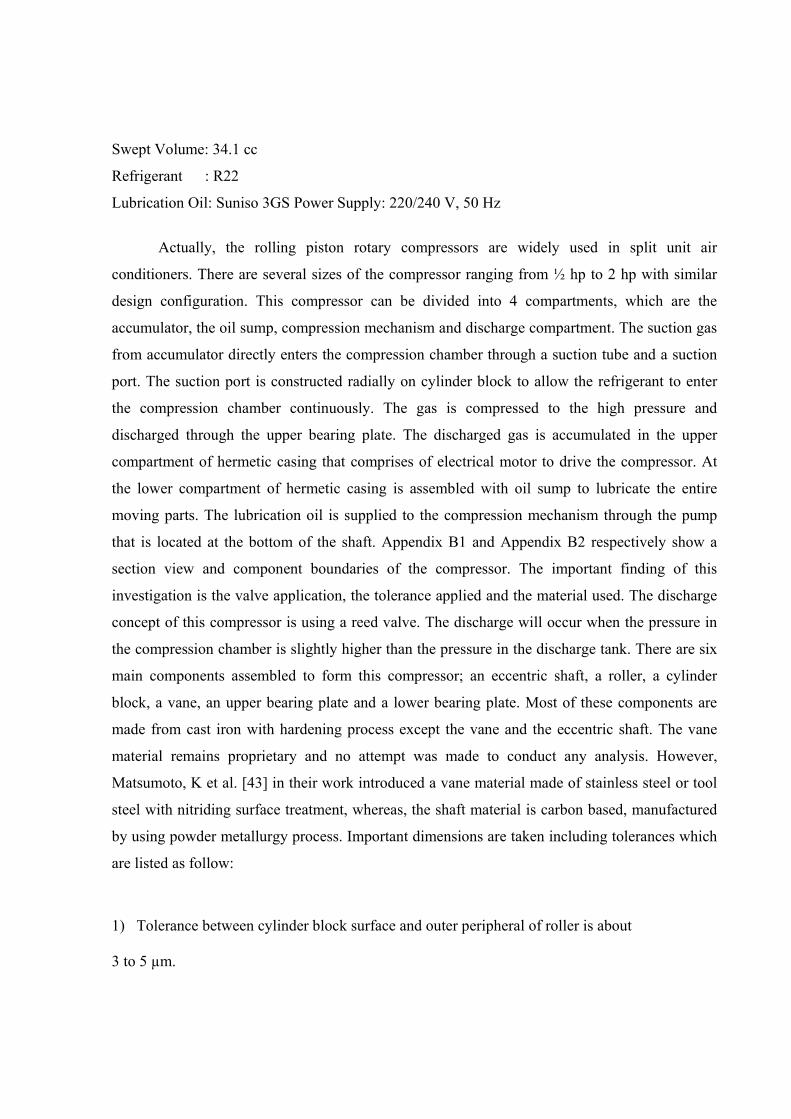
were machined on both sides to provide maximum gas entrance. Figure 2.18 shows the cylinder
block of both compressors.
(a) Patco Compressor (b) Denso Compressor
Figure 2.18: Cylinder block for sliding vane rotary compressor
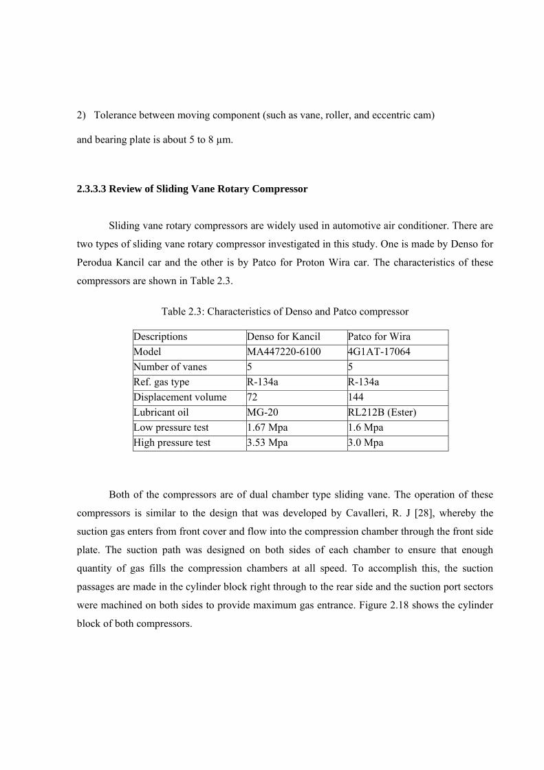
Generally, both compressors are divided into the two compartments: the suction and the
discharge as indicated by Figure 2.19.
(a) Patco compressor (b) Denso compressor
Figure 2.19: Compartments boundaries of sliding vane rotary compressor
Low-pressure gas enters the compressor chamber through the suction passage and
discharged through the discharge port at cylinder block closed to the sealing point. Each
compressors uses discharge reed valves. In Denso compressor, there are three-discharge ports
combined with three-reed valves. Whereas in Patco compressor, there are only two-discharge
port combined with two-reed valves. An investigation to the discharge ports of both compressors
was made. It was found that the discharge valve seats are different in the two compressors. In
Denso compressor, it is just separated by groove between the discharge ports and bolt holes,
whereas in Patco compressor, it has lip and groove at the discharge ports. Another important
thing in these compressors is the material used. Most of parts in these compressors are using
aluminium alloy material such as for rotor, sleeve, casing and vane. The surface of vane was
treated by hard chrome plated and rotor surface is coated by carbon. For end plate, the material
used is aluminium alloy A390 also with a carbon surface coating. Appendix C1 and C2 show
the dismantled components of these compressors.
2.4 Conclusion
There are lots of useful information that was collected from the study that has been
conducted. This information will be considered in order to produce a good design of a new rotary
compressor such as design ratio, material selection, tolerance and surface finishing. As such in
this design, the author has applied the design ratio proposed by Meece, W et al. [29]. Where, the
proposed design ratio for sliding vane rotary compressor is between 0.8 and 0.9. This ratio is
desired because it provides a wide of range to design the compression chamber. In addition, the
new rotary compressor that will be designed is differing from existing rotary compressors. Based
on the design review of the existing rotary compressors, Aluminium alloy A390 was selected to
build-up first prototype of new rotary compressor. The tolerances of rotating components were
referred to Gasche, J. L et al. [41] and measurements on rolling piston rotary compressor which
has the maximum tolerance allowances as 10 µm. The surface finish of compression components
should be equal to mirror surface to reduce friction between rubbing component.
CHAPTER 3
COMPRESSOR DESIGN AND DEVELOPMENT 3.1 Introduction
This chapter discusses the design and development of the new rotary compressor prototype
in the aspect of the compression concept, design geometry, system design, material selection and
quality of machining. The design of this compressor is based on the specification of existing
reciprocating compressor which is used in refrigerator NR- B33TA National. The volume of the
reciprocating compressor is 6.6 cm3 and the operating speed is almost 3000 rpm. 3.2 Design Step of New Compressor 3.2.1 Design of Compression Concept
This compressor is called Single Vane Rotating Sleeve Rotary Compressor because both
the vane and the sleeve rotate together with the rotor as described in 1.4. This means that the
total physical boundary of the compression chamber moves along as the gas is compressed. This
is due to the innovation where the sleeve that replaces the cylinder wall is being pushed by the
vane to rotate along. At the same time, during the first half of rotation the sleeve pulls the vane
out of the slot and during the second half, the vane is pushed back into the slot in the rotor.
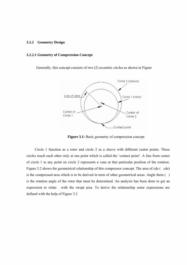
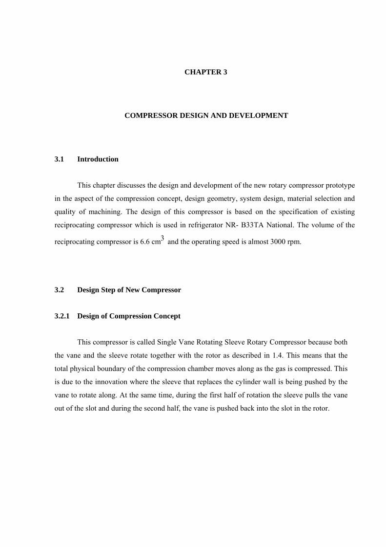
3.2.2 Geometry Design 3.2.2.1 Geometry of Compression Concept
Generally, this concept consists of two (2) eccentric circles as shown in Figure
Figure 3.1: Basic geometry of compression concept
Circle 1 function as a rotor and circle 2 as a sleeve with different center points. These
circles touch each other only at one point which is called the ‘contact point’. A line from center
of circle 1 to any point on circle 2 represents a vane at that particular position of the rotation.
Figure 3.2 shows the geometrical relationship of this compressor concept. The area of cde (�cde)
is the compressed area which is to be derived in term of other geometrical areas. Angle theta (�)
is the rotation angle of the rotor that must be determined. An analysis has been done to get an
expression to relate �with the swept area. To derive the relationship some expressions are
defined with the help of Figure 3.2
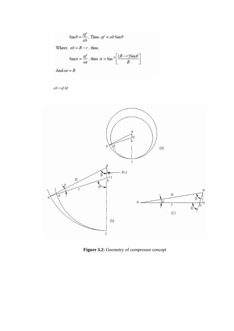
Figure 3.2: Geometry of compressor concept
eb =ef-bf
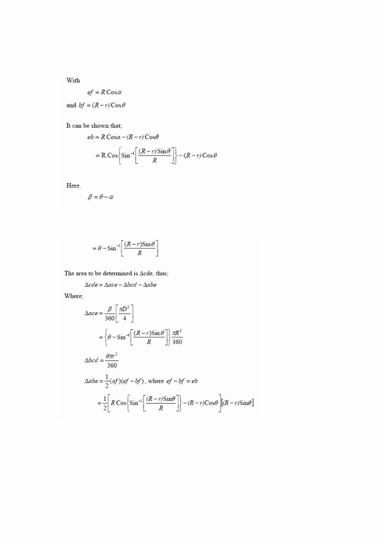
All of the equations involved are expressed in term of R, r and �respectively. The value of
� varies from 0� to 360�whereas the values of R and r are to be specified. Thus, the values of
parameters R and r must be decided to determine other parameters. Design ratio is very
important in order to determine the R and r, based on the published work the recommended value
is taken as 0.83 [29]. Thus,
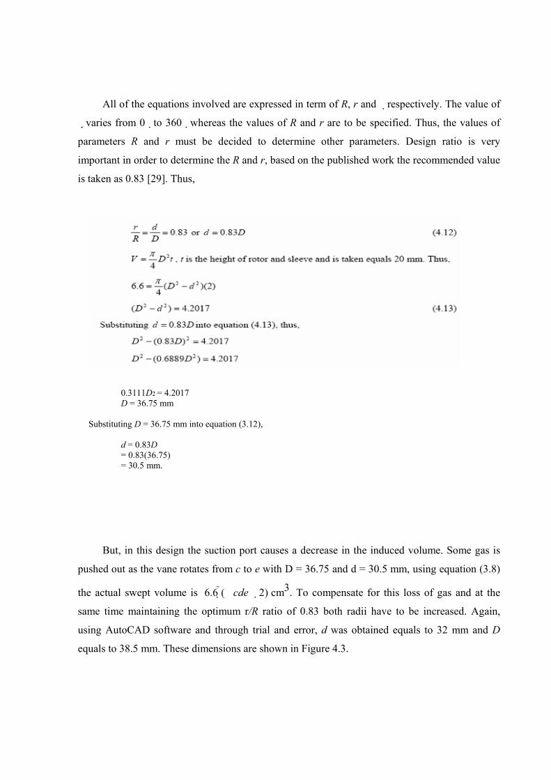
But, in this design the suction port causes a decrease in the induced volume. Some gas is
pushed out as the vane rotates from c to e with D = 36.75 and d = 30.5 mm, using equation (3.8)
the actual swept volume is 6.6 (�cde �2) cm3. To compensate for this loss of gas and at the
same time maintaining the optimum r/R ratio of 0.83 both radii have to be increased. Again,
using AutoCAD software and through trial and error, d was obtained equals to 32 mm and D
equals to 38.5 mm. These dimensions are shown in Figure 4.3.
0.3111D2 = 4.2017 D = 36.75 mm
Substituting D = 36.75 mm into equation (3.12),
d = 0.83D = 0.83(36.75) = 30.5 mm.
Suction port
e d
c
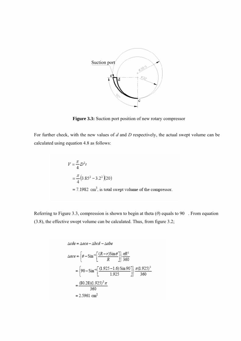
Figure 3.3: Suction port position of new rotary compressor For further check, with the new values of d and D respectively, the actual swept volume can be
calculated using equation 4.8 as follows:
Referring to Figure 3.3, compression is shown to begin at theta (θ) equals to 90�. From equation
(3.8), the effective swept volume can be calculated. Thus, from figure 3.2;
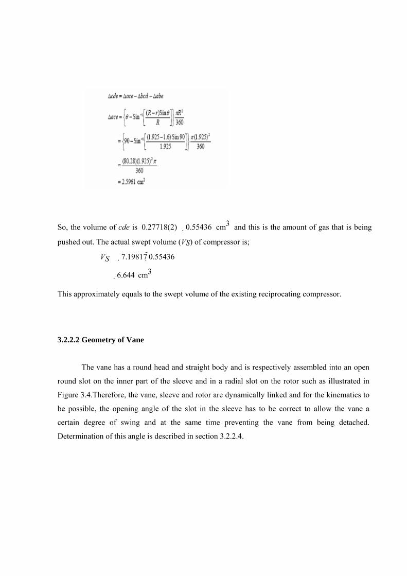
So, the volume of cde is 0.27718(2) � 0.55436 cm3 and this is the amount of gas that is being
pushed out. The actual swept volume (VS) of compressor is;
VS �7.19817 0.55436
�6.644 cm3 This approximately equals to the swept volume of the existing reciprocating compressor. 3.2.2.2 Geometry of Vane
The vane has a round head and straight body and is respectively assembled into an open
round slot on the inner part of the sleeve and in a radial slot on the rotor such as illustrated in
Figure 3.4.Therefore, the vane, sleeve and rotor are dynamically linked and for the kinematics to
be possible, the opening angle of the slot in the sleeve has to be correct to allow the vane a
certain degree of swing and at the same time preventing the vane from being detached.
Determination of this angle is described in section 3.2.2.4.
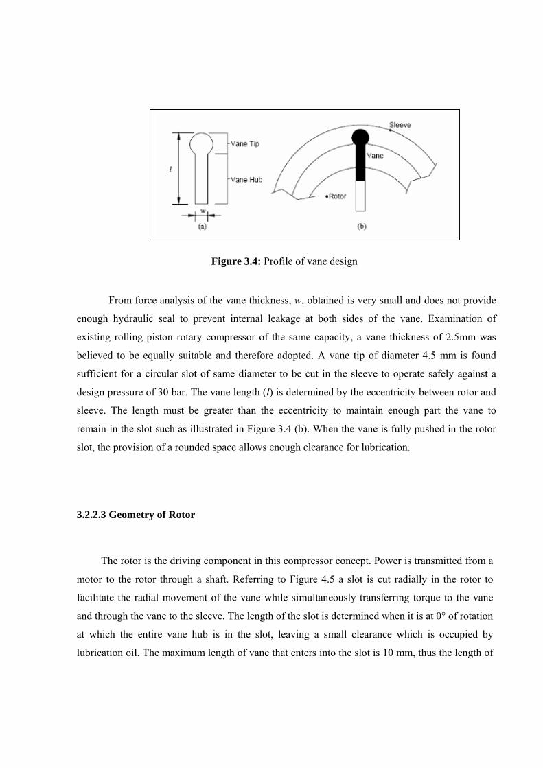
Figure 3.4: Profile of vane design From force analysis of the vane thickness, w, obtained is very small and does not provide
enough hydraulic seal to prevent internal leakage at both sides of the vane. Examination of
existing rolling piston rotary compressor of the same capacity, a vane thickness of 2.5mm was
believed to be equally suitable and therefore adopted. A vane tip of diameter 4.5 mm is found
sufficient for a circular slot of same diameter to be cut in the sleeve to operate safely against a
design pressure of 30 bar. The vane length (l) is determined by the eccentricity between rotor and
sleeve. The length must be greater than the eccentricity to maintain enough part the vane to
remain in the slot such as illustrated in Figure 3.4 (b). When the vane is fully pushed in the rotor
slot, the provision of a rounded space allows enough clearance for lubrication. 3.2.2.3 Geometry of Rotor
The rotor is the driving component in this compressor concept. Power is transmitted from a
motor to the rotor through a shaft. Referring to Figure 4.5 a slot is cut radially in the rotor to
facilitate the radial movement of the vane while simultaneously transferring torque to the vane
and through the vane to the sleeve. The length of the slot is determined when it is at 0° of rotation
at which the entire vane hub is in the slot, leaving a small clearance which is occupied by
lubrication oil. The maximum length of vane that enters into the slot is 10 mm, thus the length of
vane slot was designed to be 10.5 mm with a round shape at the end of slot. The shaft dimension
was decided equal to 10 mm diameters. This is strong enough to take the torque during
compression. To simplify machining process, the inner end of the vane slot is designed not to
touch the shaft.
Figure 3.5: Rotor profile design
3.2.2.4 Geometry of Sleeve
Referring to Figure 3.4 (b) again, the sleeve is designed with a slot having a similar profile
with that of the vane tip. The vane slot of sleeve must have opening angle to allow the vane to
swing smoothly. The vane swinging angle on the sleeve was obtained by trial and error using
AutoCAD software by rotating the mechanism as shown in Figure 1.7 in section 1.3. Using the
procedure a vane angle of 91was selected. At the opening of the slot, fillets are cut on each side
to minimise the risk of the edges being damaged during operation. The outer diameter of sleeve
was determined by force analysis but the actual value was decided to match the standard size of
the needle roller bearing. The suitable bearing selected has an inner diameter of 50 mm and a
height of 20 mm. Thus, the chosen outside diameter of sleeve is 50 mm.
3.2.3 Discharge Angle Calculation
As described previously, compression starts at pressure p1 when the vane has just rotated
over the suction port. At certain angle of rotation, the pressure reaches p2. It is at this point that the
gas must be discharged. The theoretical discharge angle can be calculated using geometrical
relationship and using AutoCAD. Both of these methods are based on the estimation of discharge
volume V2 from the following equation.
where V1 is the actual swept volume equals 6.64 cm3 and p1 and p2 are specified values. The
polytropic index (n) was calculated using equation 3.6
where, T1, p2 and p1 are actual values measured from experiment. The value of T2 was estimated
from isentropic process of compression (s1 = s2). The data of T1, p1, and p2 were taken from a
preliminary run of the experiment at which the freezer compartment temperature was constant at -
15°C as below:
T1 = 26.4oC p2 = 9.8 Bar G p1 = 0 Bar G
Therefore the values of s1 and s2 were estimated equal to 1.036 kJ/kg K. Based on NIST
REFPROP software from ASHRAE, the value of T2 is 105.20C. Thus, using equation 3.6, the
polytropic compression index (n) is obtained equal to 1.11. From equation 3.7, the discharge
volume (V2) can be calculated as equal to 0.7866 cm3.The theoretical discharge angle was
determined based on the area of A2 which is equal to 0.3933 cm2. By using AutoCAD, it was
found that the corresponding discharge angle is about 258oC. 3.2.4 Design of Compression Component
The components that creates the compression chamber such as rotor, vane and sleeve
were designed based on the geometrical dimension determined earlier. Height of these
components are equal to 20 mm with tolerance of 0 mm to -10 µm. The rotor was designed as
one piece with shaft and dimension of the shaft was matched with the needle roller bearing
[54]. The inner diameter (ID) of bearing 1 is 8 mm and ID of bearing 2 is 10 mm. The
tolerance for radius of rotor must be determined by considering the maximum tolerance of
contact point between rotor and sleeve. Since the tolerance of contact point was decided as 7.5
�m, the rotor tolerance was obtained as –5 µm to 0 µm in diameter. All of above discussion is
illustrated in Figure 3.6.
Figure 3.6: Detail of rotor design
As mentioned earlier, the sleeve needs to be supported with a bearing which has a 50 mm
ID. A needle roller bearing of 50 mm ID, SKF 5020 is found suitable. This bearing has a 58 mm
outer diameter. The tolerance of sleeve inner diameter should be referred to the rotor tolerance
and sleeve/rotor contact point clearance. Thus, the tolerance of sleeve inner diameter was
obtained as 0 µm to +10 µm. The vane was designed based on the geometry that has been
discussed with 20 mm height. The tolerance of vane height is equal to the tolerance of rotor and
sleeve height whereas the tolerance of vane width was obtained as –12 µm to 0 µm and vane slot
at rotor was obtained as 0µm to +10 µm. The cylinder block was designed with center bore to
insert the needle roller bearing HK 5020 SKF and all compression components. Height of
cylinder block was designed equal to 20 mm with +5µm tolerance. Figure 4.7 shows the
disposition of bearing, sleeve, rotor and vane into cylinder block.
Figure 3.7: Compression parts assembly into cylinder block
End plates form an enclosure to the compression chamber as well as to support and to
alignment the shaft and to provide smooth rotation by installing a bearing on each end plate.
Referring to Figure 4.8, at the front end plate, it was assembled with HK 1010 needle roller
bearing (2) and oil seal (3) to prevent the high-pressure gas leaking out of the compression
chamber. Needle roller bearing HK 0808 (1) was assembled at rear end plate. The passages of
suction and discharge are through the front end plate and rear end plate respectively.
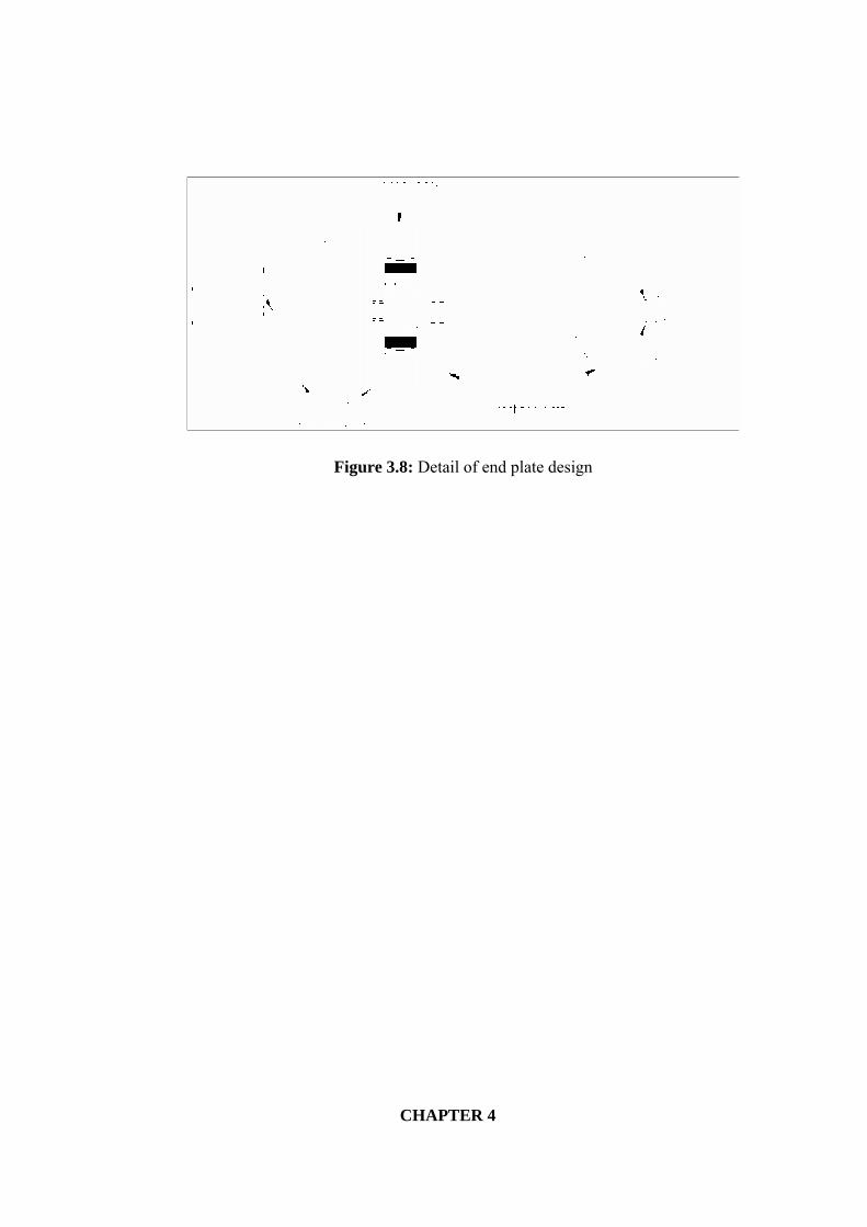
Figure 3.8: Detail of end plate design
CHAPTER 4
CONCLUSION AND SUGGESTIONS 4.1 Conclusion
A new idea of a single vane rotating sleeve rotary compressor was conceived. The concept
development and literature study carried out in this report is a preliminary step in design and
development process of the new concept. The patent for the invention has been duly filed. The
reference patent number is PI 20014899 entitled Single Vane Rotary Compressor under
Malaysian Patent Office.
The new concept has attracted investors from local companies for commercialization
activities. One such company is Thermocompressor Engineering Sdn Bhd who is keen in
developing the concept further and commercializes it for the small portable air conditioning
market. Due to the concept advantage, it is possible to develop a compressor which is smaller
in size yet producing the same cooling capacity compared to other concept within the same
class. The project had received research grant from the government under MTDC with a total
amount of RM 3.4 million with half of the amount is provided by the company. Currently the
company is allocating the required amount of RM 1.7 million before the project can progress
further.
Works are already started in developing a working prototype for the compressor as well
as commissioning a test system for measuring the performance of the compressor. The research
work will be continued on other research grant (74522) as the current grant is unable to support
the research any further.
4.2 Suggestions
Every new invention is followed by further development work. The short few months
spent was felt not enough to develop a working prototype whereby the new rotary compressor
can be commercialized and accepted by the open market. The following suggestion are
proposed to be considered to be taken so as the innovation will lead to a successful application
of the new invention on to the refrigeration plants like domestic refrigerator and split unit air-
conditioning system.
1) A comprehensive research and development work should be done in the
near future to fully utilize the advantage of the new compressor in the
open market.
2) The development work should include in concept improvement as well
as a through engineering analysis covering kinematics and dynamics of
the concept to final product durability and fabrication method.
3) Since the new concept is universal, work should also cover other
applications such as automobile air conditioning or hydraulic pumps and
vacuums.
4) A test rig should be developed to test the performance of the new
compressor and a fair comparison should be made to that of existing
compressor readily available in the market
References
1. Jordan, R. C. and Priester, G. B. (1985). “Refrigeration and Air Conditioning System.” 2nd edition. Prentice-Hall of India Private Limited, New Delhi. 3 – 15.
2. Whitman, C. W., Johnson, W. M and Tanczyk, J. A. (2000). “Refrigeration and
Air Conditioning Technology.” 4th edition. Delmar Thomson Learning, USA. 22
– 25.
3. Shan, K. Wang, Zalman Lavan and Norton, P. (2000). “Air Conditioning and
Refrigeration Engineering”. CRC Press, New York. 83 – 84.
4. Shan, K. Wang. (1993). “Handbook of Air Conditioning and Refrigeration.” Mc
Graw-Hill Inc., New York. 10.22 – 10.23.
5. Whitman, C. W. and Johnson, W. M. (1995). “Refrigeration and Air Conditioning Technology.” 3th edition. Delmar Thomson Learning, USA. 363 –
366.
6. Langley, B. C. (1978). “Refrigeration and Air Conditioning.” Prentice-Hall
Company, Reston Virginia. 74 – 77.
7. Air Conditioning and Refrigeration Institute (ARI) (1998). “Refrigeration and
Air Conditioning.” 3rd edition. Prentice Hall, USA. Pg. 416 - 437.
8. Vladimir Chlumsky (1966). “Reciprocating and Rotary Compressor”. SNTL
Publisher of Technical Literature, Prague-Checkoslovakia. 275 – 278.
9. Dossat, R. J. (1978). “Principles of Refrigeration.” John Wiley & Sons, New
York. 462 – 465.
10. ASHRAE (2000). “ASHRAE Handbook CD: HVAC Systems and Equipment”.
CD edition. ASHRAE, USA. 34.9 – 34.11.
11. Chlumsky, V (1966). “Reciprocating and Rotary Compressor”. SNTL
Publisher of Technical Literature, Prague-Checkoslovakia. 286.
12. Shan, K. Wang. (1993). “Handbook of Air Conditioning and Refrigeration.” Mc
Graw-Hill Inc., New York. 10.29
13. Shan, K. Wang, Zalman Lavan and Norton, P. (2000). “Air Conditioning and
Refrigeration Engineering”. CRC Press, New York. 83.
14. Langley, B. C. (1978). “Refrigeration and Air Conditioning.” Reston Publishing
Company Inc, Reston Virginia. 65. 15. Joel, R. (1996). “Basic Engineering Thermodynamic.” 5th edition. Addison
Wesley Longman Limited, England. 392 – 394.
16. Dossat, R. J. (1978). “Principles of Refrigeration.” 2nd edition. John Wiley &
Sons, New York. 271.
17. Kinney, J. R. (1911). “Rotary Pump.” (U.S. Patent 993, 530).
18. Buchanan, J. C. and Hubacker, E. F. (1933). “Discharge Valve.” (U.S. Patent
1, 931, 017).
19. Warrick, L. K., Muskegen Heights and LaFlame, F. E. (1952). “Compressor-
Motor Assembly.” (U.S. Patent 2, 612, 311)
20. Dreiman, N. I. (1998). “Suction Inlet For Rotary Compressor.” (U.S. Patent
5, 829, 960).
21. Caio, M. F. N. and Costa, D (1991). “Discharge System For Rotary Rolling
Piston Compressor.” (U.S. Patent 5, 004, 408).
22. Kang, Heui-Jong (1998). “Rotary Compressor Having A Roller Mounted
Eccentrically In A Cylindrical Chamber of A Rotatable Cylinder.” (U.S. Patent
5, 733, 112).
23. Gillespie, J. E. (1873). “Improvement In Rotary Pump.” (U.S. Patent 141, 000).
24. Walter, J. P. (1923). “Rotary Pump.” (U.S. Patent 1, 444, 269).
25. Camilo, V. N. (1954). “Rotary Vacuum And Compressor Pump.” (U.S. Patent
2, 672, 282).
26. Adalberd, G., Jurgen Hess and Linder, E (1974). “Pressure-Sealed Compressor.”
(U.S. Patent 3, 852, 003).
27. Adalbert, G. and Vysiotis, T. (1985). “Vane Compressor, Particularly A Cooling
Medium Compressor For Use In Air-Conditioning Equipment of A Vehicle.”
(U.S. Patent 4, 505, 656).
28. Cavalleri, R. J. (1994). “High Performance Dual Chamber Rotary Vane
Compressor.” (U.S. Patent 5, 302, 096).
29. Meece, W. (1974). “Design of Oil-Less Compressor and Pumps.” Proc. of the
1974 Purdue Compressor Technology Conference. Indiana, USA. 250 – 257.
30. Pendeya, P. and Soedel, W. (1978). “Rolling Piston Type Rotary Compressors
with Special Attention to Friction and Leakage.” Proc. of the 1978 Purdue
Compressor Technology Conference. Indiana, USA. 209 – 217.
31. . Matsuzaka, T. and Nagatomo, S. (1982). “Rolling Piston Type Rotary
Compressors Performance Analysis.” Proc. of the 1982 Purdue Compressor
Technology Conference. Indiana, USA. 149 – 158.
32. Kawai, H. (1984). “Efficiency Improvement in Rolling Piston Type Rotary
Compressors.” Proc. of the 1984 International Compressor Engineering
Conference at Purdue. Indiana, USA. 299 – 306.
33. Nagatomo, S., Sakata, H., Tago, M. and Hattori, H. (1984). “Performance
Analysis of Rolling Piston Type Rotary Compressors for Household
Refrigerators.” Proc. of the 1984 International Compressor Engineering
Conference at Purdue. Indiana, USA. 291 – 298.
34. Nomura,T., Ohta, M., Takeshita, K. and. Ozawa Y. (1984). “Efficiency
Improvement in Rotary Compressors.” Proc. of the 1984 International
Compressor Engineering Conference at Purdue. Indiana, USA. 307 – 314.
35. Shintaku, H., Ikoma M., Hasegawa, H., Nishiwaki, F., Harada, T., Nakata, H.
and Kurimoto, M. (2000). “Experimental and Theoretical Study of an Advanced
Rotary Compressors.” Proc. of the 2000 International Compressor Engineering
Conference at Purdue, Vol. (1). West Lafayette, Indiana. Purdue University, 753
– 760.
36. Huang, Y., Harte, S., Sud, L., Kheterpal, V. and Strikes, G. (2000). “A Novel
Automotive Two-Stage Air Conditioning Compressor.” Proc. of the 2000
International Compressor Engineering Conference at Purdue, Vol. (1).
West Lafayette, Indiana. Purdue University, 403 – 408.
37. Huang, Y., Harte, S. and Sud, L. (1998). “Dynamic Parameter Optimization of
an Automobile Air Conditioning Compressor Using Taguchi Method.” Proc. of
the 1998 International Compressor Engineering Conference at Purdue, Vol. (1).
West Lafayette, Indiana. Purdue University, 260 – 266.
38. Sud, L., Dalal, H., Harte, S. and Yong, Huang (2000). “Development of rotary Compressor for Semi / Trailer Truck
Applications.” Proc. of the 2000
International Compressor Engineering Conference at Purdue. Vol. (1). West Lafayette, Indiana. Perdue
University, 397 – 401.
39. Reed, W. A. and Hamilton, J. F. (1980). “Internal Leakage Effects in Sliding Vane Rotary Compressor.” Proc. of the
1980 Purdue Compressor Technology Conference. Indiana, USA. 112 – 117.
40. Rodgers, R. J. and Nieter, J. J. (1996). “Comprehensive Analysis of Leakage in Rotary Compressors.” Proc. of the
1996 International Compressor Engineering Conference at Purdue. Indiana, USA. Vol. 1. 287 – 293.
41. Gasche, J. L., Ferreira, R. T. S. and Prata, A. T. (1998). “Transient Flow of the Lubricant Oil through the Radial
Clearance in Rolling Piston Compressors.” Proc. of the 1998 International Compressor Engineering Conference at
Purdue. Vol. (1). West Lafayette, Indiana. Purdue University, 25 – 30.
42. Komatsubara, T., Okajimi, M., Hoshino, H. and Obokata, Y. (1990). “Fiber
Reinforced Aluminium Alloy for the Moving Parts of Rotary Compressor.”
Proc. of the 1990 International Compressor Engineering Conference at Purdue, Vol. (1). West Lafayette, Indiana:
Purdue University, 105 – 112.
43. Matsumoto, K., Sunaga, T., Matsuura, D. and. Takabashi, Y (2003). “Rotary
Compressor.” (U.S. Patent 6, 592, 347).
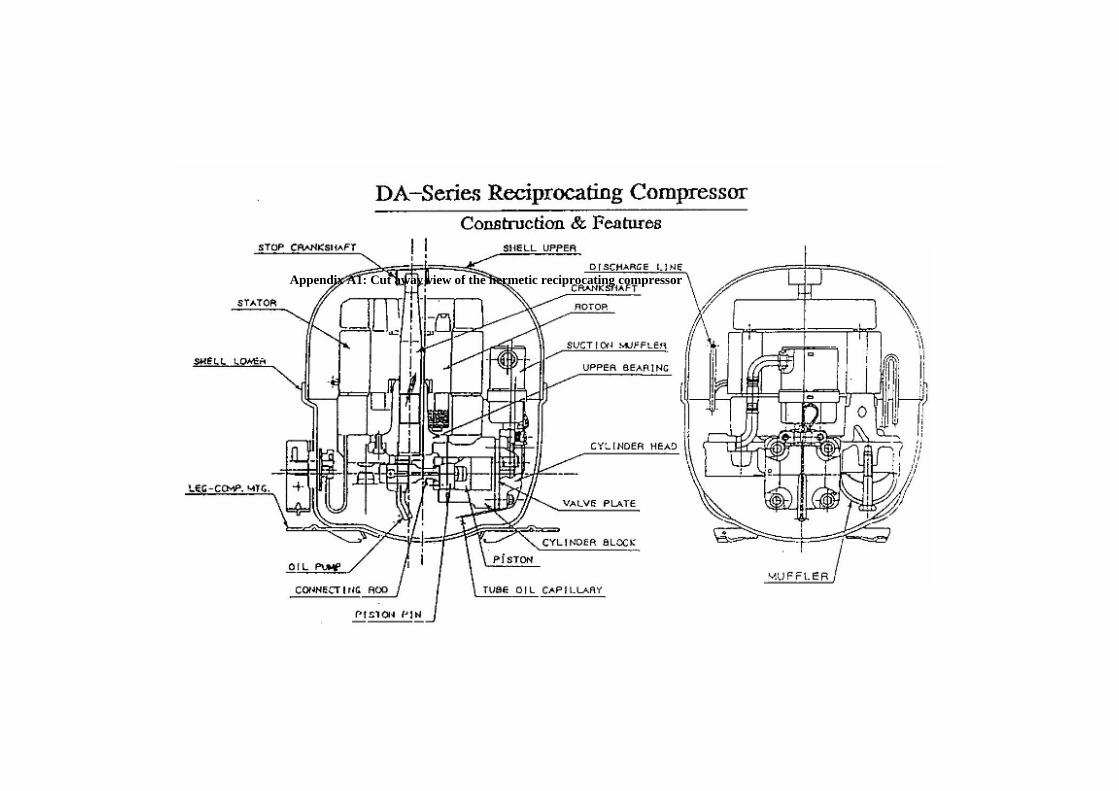
Appendix A1: Cut away view of the hermetic reciprocating compressor
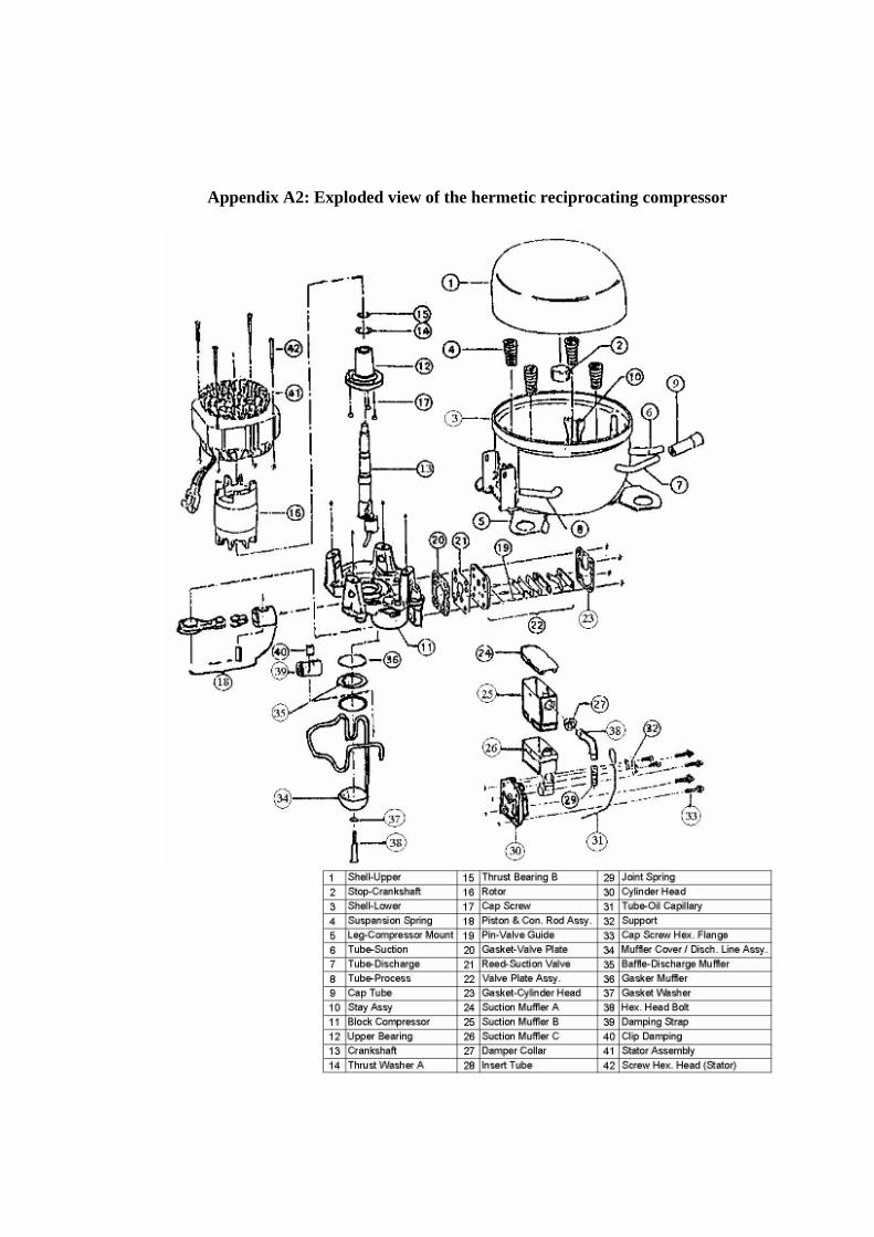
Appendix A2: Exploded view of the hermetic reciprocating compressor
Refer to the manual of this compressor, there are 42 parts involved in the assembly and
to ensure that the compressor is able working properly. Each of parts that involved
having distinctive function such as described below;
1 & 3 – Upper and Lower Shell
These shells are welded together to form a hermetic seal.
2 – Stop Crankshaft
This is spot welded to the upper shell to prevent the toppling of pump assembly especially
during transportation of the compressor. It also prevents the pump assembly dislocated
from the spring.
4 – Suspension Spring
To isolate the vibration of the pump assembly from the shell and to provide free
movement of the pump assembly during compressor starting and stopping.
5 – Leg Mounting
To facilitate the mounting of the compressor to the cabinet.
6, 7 & 8 – Tube Suction, Tube Discharge and Tube Process
Tube suction and tube discharge are to facilitate the connection of tube suction to the
evaporator and tube discharge to the condenser of the cabinet. Tube process is to
facilitate the charging of refrigerant to the system, vacuuming of the system, as well as the
charging to oil to the compressor.
9 – Cap Tube
To seal off tube process, discharge and suction from foreign particles, dust, moisture and
others.
10 - Stay
To facilitate the suspension springs mounting.
11 – Block
Attachment of upper bearing, discharge muffler, stator and valve system.
12 – Upper Bearing
Act as a bearing support for the rotating mechanism.
14 & 15 – Thrust Washer
To share the weight of the rotor acting on the upper bearing surface.
20 – Gasket Valve Plate
With 5 different of thickness to adjust the top clearance to the minimal so as to eliminate top
noise and maximize compressor efficiency.
21 – Reed Suction Valve
During the suction process, it allows the refrigerant to enter the cylinder. During the
compression and discharge process, it prevents the refrigerant from escaping into the
suction chamber.
22 – Valve Plate Assembly
Discharge Reed – During the suction process, it prevents the discharge gas from
returning to the cylinder, and during the discharge process, it allows the refrigerant to be
discharged to the discharge chamber, thus serving as a control valve.
Valve Plate – Acts as a base plate for the mounting of discharge reeds, it has discharge and
suction holes, discharge and suction passes and guide pin holes on it.
23 – Gasket Cylinder Head
To prevent leakage of discharge gas and leakages between suction and discharge
chamber.
24, 25 & 26 – Suction Muffler
To reduce the temperature of suction gas so as to improve compressor efficiency and
reduce noise.
27 – Damper Collar
To prevent dislocation of the insert tube with the inlet of the suction muffler, and to
absorb the vibration of the pump assembly.
29 – Joint Spring
To absorb the lateral vibrational movement of the pump assembly
30 – Cylinder Head
To seal the valve plate assembly and to isolate the suction and discharge chamber.
31 – Tube Oil Capillary
To supply oil to the cylinder serving as lubricant and to reduce the leakage of high
pressure gas.
34 – Muffler Cover & Discharge Line Assembly
The muffler cover is fastened to the block forming the discharge muffler, which reduces
the discharge gas pulsation and noise. The discharge line acts as a passage between the
discharge muffler and the tube discharge.
35 – Baffle Discharge Muffler
It reduces discharge gas pulsation and noise.
39 – Damping Strap
To reduce the vibration on the discharge line.
Lubricating Oil
For lubrication, cooling, and sealing purpose. Lubrication is required to reduce friction and
wear.
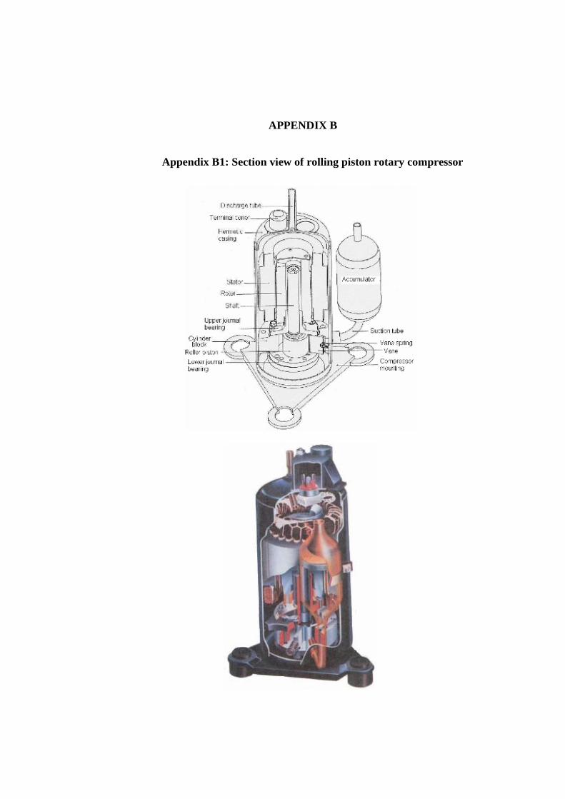
APPENDIX B
Appendix B1: Section view of rolling piston rotary compressor
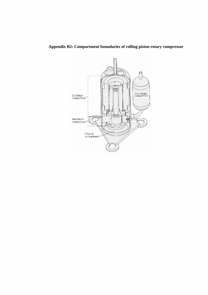
Appendix B2: Compartment boundaries of rolling piston rotary compressor
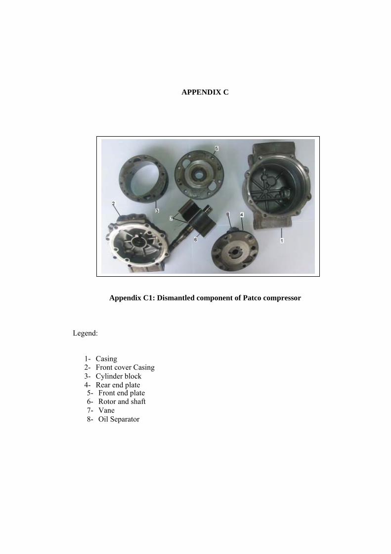
APPENDIX C
Appendix C1: Dismantled component of Patco compressor
Legend:
1- Casing 2- Front cover Casing 3- Cylinder block 4- Rear end plate 5- Front end plate 6- Rotor and shaft 7- Vane 8- Oil Separator
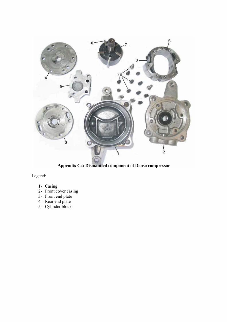
Appendix C2: Dismantled component of Denso compressor Legend:
1- Casing 2- Front cover casing 3- Front end plate 4- Rear end plate 5- Cylinder block