j. - eprints.uthm.edu.myeprints.uthm.edu.my/id/eprint/674/1/24_pages_from_smart_thermal... ·...
TRANSCRIPT


J. * .f ll, •
" " t
KOLEJ UNIVERSITI TEKNOLOGI TUN HUSSEIN ONN
BORANG PENGESAHAN STATUS TESIS·
JUDUL: SMART THERMAL COMFORT SYSTEM: A DEVELOPMENT OF THE FUNDAMENTAL CONTROL ALGORITHM.
SESI PENGAJIAN: 2004/2005
Saya SHAZMIN ANIZA BINTI ABDUL SHUKOR (HURUF BESAR)
mengaku membenarkan tesis (PSM/ Sarjana/ Doktor Falsafah)* ini disimpan di Perpustakaan dengan syarat-syarat kegunaan seperti berikut:
1. Tesis adalah hakmilik Kolej Universiti Teknologi Tun Hussein Onn. 2. Perpustakaan dibenarkan membuat salinan untuk tujuan pengajian sahaja. 3. Perpustakaan dibenarkan membuat salinan tesis ini sebagai bahan pertukaran antara
institusi pengajian tinggi. 4. **Sila tandakan (.y)
ILII sum (Mengandungi maklumat yang berdaIjah keselamatan atau kepentingan Malaysia seperti yang termaktub di dalam AKTARAHSIARASMI 1972) o TERHAD (Mengandungi maklumat TERHAD yang telah ditentukan oleh organisasil badan di mana penyelidikan dijalankan
II ~ II T1DAK TERHAD
Alamat Tetap:
~ \
DJIi~h:t(an oleh
~~-::::------(TANDATM GAN PENYELIA)
14, Tmn. Tok Perdana, Jln Raja Omar, 32000 Sitiawan, Perak Darul Ridzuan.
PM. DR ZAINAL ALAM HARON (Nama Penyelia)
Tarikh: 22 NOVEMBER 2004 Tarikh: 22 NOVEMBER 2004
CATATAN: * Potong yang tidak berkenaan. ** Jika tesis ini SULIT atau TERHAD, sila lampirkan surat daripada pihak berkuasa
organisasi berkenaan dengan menyetakan sekali sebab dan tempoh tesis ini perlu dikelaskan sebagai SULIT atau TERRAD .
• Tesis dimaksudkan sebagai tesis bagi Ijazah Doktor Falsafah dan Satiana secara penyelidikan, atau disertasi bagi pengajian secara ketia kursus dan penyelididikan, at au Laporan Projek Sarjana Muda (PSM).
"l/ We hereby acknowledge that the scope and quality of this report is qualified for
the award of the Bachelor / Master / Doctor of Philosophy degree of
~I~.c;:.tri~HJ.Enw~.~rmg".
Name of Supervisor
Date
Signature
: PRQF.,J:?R .. KA.R.L.KQHLHQf : 2.~.NQY.E~.ER..2.Q.9.4
Name of Co-Supervisor: A.S.SQ.C, ....... .F.:.P.R.:.ZAJN.AL.AL.AM . .HMQN Date : 2.~ .. NQY.EM~.ER..2.Q.Q4
Signature
Name of Co-Supervisor: AS.s.QCc.P.R.QfJ2K.2JJ.L.AZHAR.Z.ABJP.JAMtJ., Date : 21.NQY.EM~.ER..2.Q.Q4
SMART THERMAL COMFORT SYSTEM: A DEVELOPMENT OF THE
FUNDAMENTAL CONTROL ALGORITHM
SHAZMIN ANIZA BINTI ABDUL SHUKOR
THIS PROJECT REPORT IS SUBMITTED IN
PARTIAL FULFILLMENT OF THE REQUIREMENTS FOR THE DEGREE OF
MASTER OF ELECTRICAL ENGINEERING
FACULTY OF ELECTRICAL ENGINEERING
KOLEJ UNIVERSITI TEKNOLOGI TUN HUSSEIN ONN
NOVEMBER 2004
1

II
"All the trademark and copyrights use herein are property of their respective owner.
Reference of information from other sources are quoted accordingly; otherwise the
information presented in this report is solely work ofthe author".
Signature ....... U; ...................... . Name of Author : .S.H!.\[email protected]~.S.J:HJKO'R.
Date ~.7..NQY.E~E.R2.QQ1

To my parents, Abdul Shukor Shamsuddin and Hamidah Mohd. Yusop,
to my sister, Suriati Akmal, and my fiance, Afdzan Rizal Abdul Razak.
You are my inspiration.
1ll
ACKNOWLEDGEMENT
First and foremost, praise to Allah S.w.t. for the given time and energy in
developing this project. Without His permission, it is impossible to fmish the task on schedule.
IV
Next, my gratitude goes to Prof. Karl Kohlhoffrom University of Applied
Science, Cologne, Germany, for his willingness in supervising this project. His
assistance and guidance throughout the whole duration of this project will not be
forgotten. Not forgetting to my co-supervisors from Kolej Universiti Teknologi Tun
Hussein Onn (KUiTTHO) and Kolej Universiti Kejuruteraan Utara Malaysia
(KUKUM), Assoc. Prof. Dr. Zainal Alam bin Haron and Assoc. Prof. Dr. Zul Azhar bin
Zahid Jamal for their help when needed. The encouragement given has always been a
spirit for me in carrying out the project.
Special thanks to my colleagues - in KUiTTHO, KUKUM as well as from
University of Applied Science Cologne, for their help and guidance in ensuring that
these project a success. To all staff and lecturers of Faculty of Electrical Engineering
and Centre for Graduate Studies, KUiTTHO, thank you for their valued time spent in
helping and supervising the development of this project.
Last but not least, my appreciation towards everybody who has been involved
directly or indirectly in making this project a success.
v
ABSTRACT
This paper reports on the development of the fundamental algorithm for a smart
thermal comfort system. Using Predictive Mean Vote (PMV) as a means of measuring
thermal comfort, this system would able the user to define their own expression towards
the surroundings, from slightly warm to slightly cold. Here, the operator only needs to
insert its respective value ofPMV (ranging from -1 to + 1) and the system will generate
the compressor and fan of the air conditioning system so that it will create a thermally
comfortable environment, based on the operator's desires. This differentiates the system
with the conventional air conditioning system where the operator needs to set separately
fan speed and degree of cooling. The PMV value here will be calculated as input instead
of the normal PMV equation where these values depend on the air temperature, relative
humidity and air velocity. All these parameters values are set from the standard range
allowed by the ISO 7730 of thermal comfort at a workplace for sedentary activity. Since
previous researches use PMV as the output value, the help of Microsoft Excel is used to
obtain air temperature and air velocity for respective values ofPMV. Finally, the
fundamental stage for experimentation step is implemented by building a working
region in allowing the PID (Proportional, Integrative, Derivative) controller to control
its duty cycle.
VI
ABSTRAK
Laporan ini menyentuh tentang pembangunan algoritma asas bagi sebuah sistem
keselesaan haba yang pintar. Dengan menggunakan 'Predictive Mean Vote (PMV),
sebagai cara untuk mengukur peringkat keselesaan haba, sistem ini berupaya untuk
membenarkan pengguna mendefinisikan tahap keselesaan masing-masing terhadap
persekitaran. Dengan cara ini, pengguna hanya periu memasukkan nilai 'PMV' mereka
(dari -1 ke + 1) dan berpandukan nilai ini, sistem akan mengawal kompressor dan kipas
sistem penghawa dingin mengikut kehendak pengguna. Ini dapat menghasilkan situasi
selesa kepada pengguna. Kaedah ini berbeza dengan sistem penghawa dingin yang sedia
ada memandangkan sistem yang ada sekarang hanya membenarkan pengguna
mengawal keselesaan bilik dengan mengatur nilai suhu bilik dan kelajuan kipas secara
manual. Dalam projek ini, nilai 'PMV' akan digunakan sebagai input, berbeza dengan
kajian dan projek yang sedia ada yang menggunakan 'PMV' sebagai keluaran. Di sini,
nilai 'PMV' bergantung kepada suhu angin, kelembapan dan kelajuan angin. Kesemua
parameter ini dikira berdasarkan standard yang dikeluarkan oleh ISO 7730 bagi
keselesaan haba. Memandangkan hampir kesemua kajian terdahulu menggunakan
'PMV' sebagai nilai keluaran, bantuan daripada 'Microsoft Excel' digunakan untuk
mendapatkan suhu dan kelajuan angin mengikut 'PMV'. Kaedah terakhir yang
digunakan di dalam projek ini adalah dengan membina kawasan kerja bagi suhu dan
kelajuan angin untuk membenarkan pengawal 'PID (proportional, Integrative,
Derivative)' mengawal kitar tugas sistem pintar ini kelak.
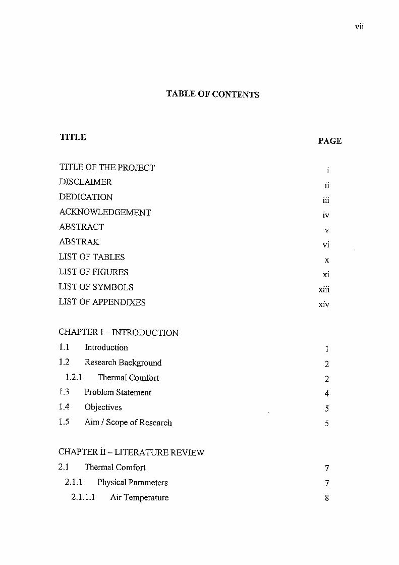
TABLE OF CONTENTS
TITLE
TITLE OF THE PROJECT
DISCLAIMER
DEDICATION
ACKNOWLEDGEMENT
ABSTRACT
ABSTRAK
LIST OF TABLES
LIST OF FIGURES
LIST OF SYMBOLS
LIST OF APPENDIXES
CHAPTER I - INTRODUCTION
1.1 Introduction
1.2 Research Background
1.2.1 Thermal Comfort
1.3 Problem Statement
1.4 Objectives
1.5 Aim / Scope of Research
CHAPTER II - LITERATURE REVIEW
2.1 Thermal Comfort
2.1.1 Physical Parameters
2.1.1.1 Air Temperature
PAGE
11
111
IV
V
VI
x Xl
Xlll
XIV
1
2
2
4
5
5
7
7
8
VII
Vlll
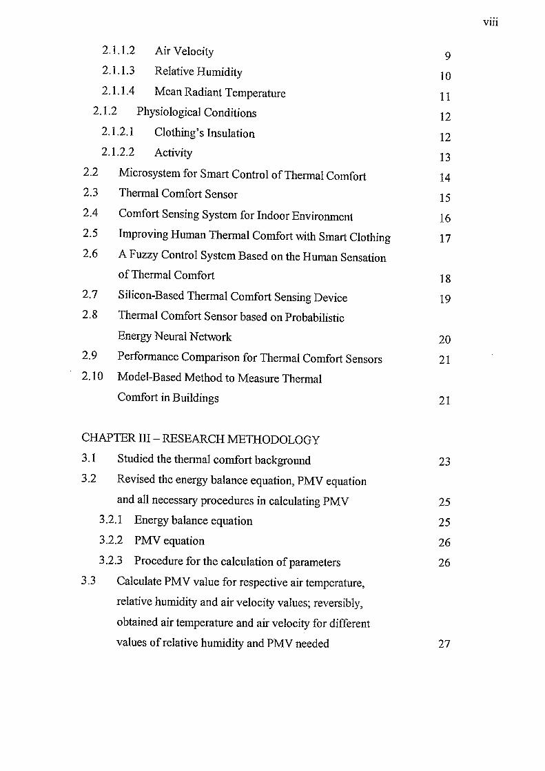
2.1.1.2 Air Velocity 9 2.1.1.3 Relative Humidity 10 2.1.1.4 Mean Radiant Temperature 11
2.1.2 Physiological Conditions 12 2.1.2.1 Clothing's Insulation 12 2.1.2.2 Activity 13
2.2 Microsystem for Smart Control of Thermal Comfort 14 2.3 Thermal Comfort Sensor 15 2.4 Comfort Sensing System for Indoor Environment 16 2.5 Improving Human Thermal Comfort with Smart Clothing 17 2.6 A Fuzzy Control System Based on the Human Sensation
of Thermal Comfort 18 2.7 Silicon-Based Thermal Comfort Sensing Device 19 2.8 Thermal Comfort Sensor based on Probabilistic
Energy Neural Network 20 2.9 Performance Comparison for Thermal Comfort Sensors 21 2.10 Model-Based Method to Measure Thermal
Comfort in Buildings 21
CHAPTER III - RESEARCH METHODOLOGY
3.1 Studied the thermal comfort background 23 3.2 Revised the energy balance equation, PMV equation
and all necessary procedures in calculating PMV 25 3.2.1 Energy balance equation 25 3.2.2 PMV equation 26 3.2.3 Procedure for the calculation of parameters 26
3.3 Calculate PMV value for respective air temperature,
relative humidity and air velocity values; reversibly,
obtained air temperature and air velocity for different
values of relative humidity and PMV needed 27
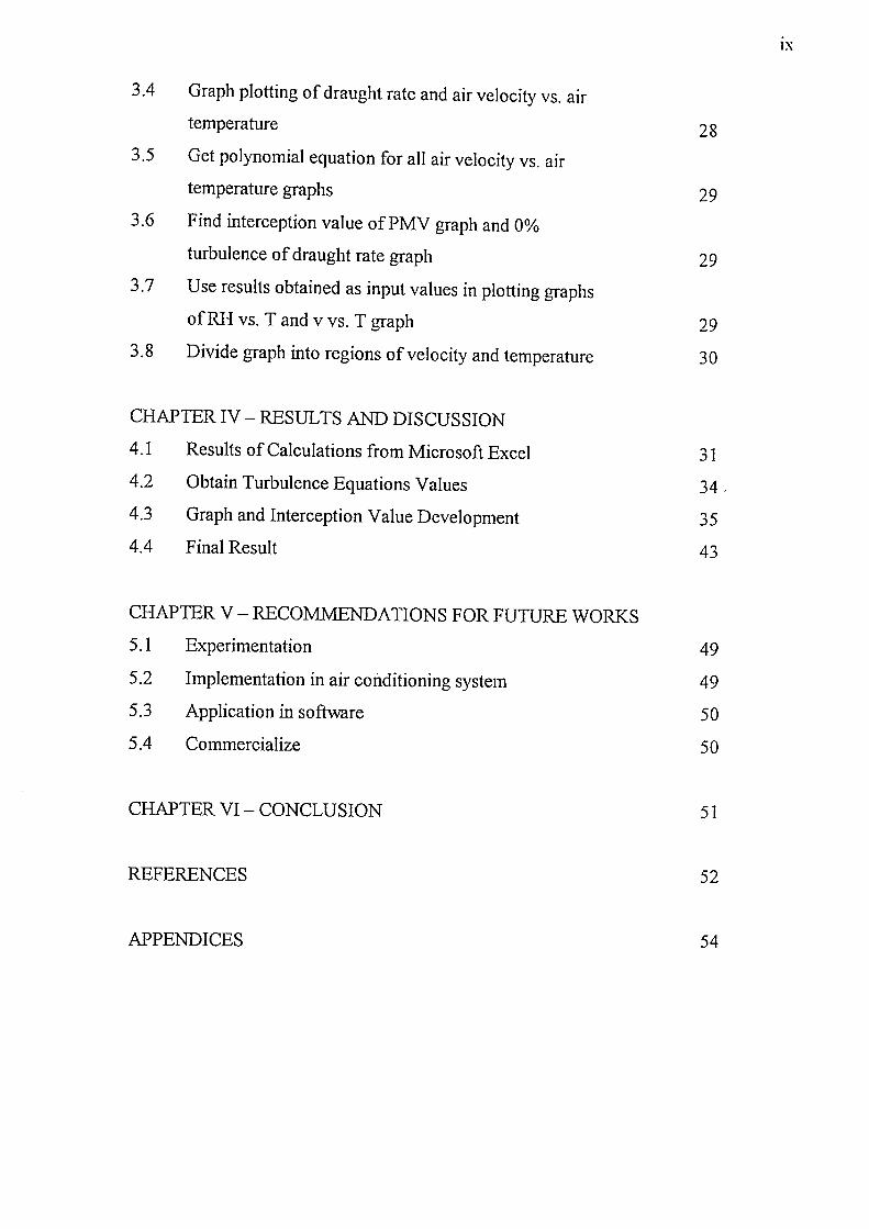
3.4 Graph plotting of draught rate and air velocity vs. air
temperature
3.5 Get polynomial equation for all air velocity vs. air
temperature graphs
3.6 Find interception value ofPMV graph and 0%
turbulence of draught rate graph
3.7 Use results obtained as input values in plotting graphs
of RH vs. T and v vs. T graph
3.8 Divide graph into regions of velocity and temperature
CHAPTER IV - RESULTS AND DISCUSSION
4.1 Results of Calculations from Microsoft Excel
4.2 Obtain Turbulence Equations Values
4.3 Graph and Interception Value Development
4.4 Final Result
CHAPTER V - RECOMMENDATIONS FOR FUTURE WORKS
5.1 Experimentation
5.2 Implementation in air conditioning system
5.3 Application in software
5.4 Commercialize
CHAPTER VI - CONCLUSION
REFERENCES
APPENDICES
28
29
29
29
30
31
34,
35 43
49
49
50
50
51
52
54
IX
x
LIST OF TABLES
NO. OF TABLE TITLE PAGE
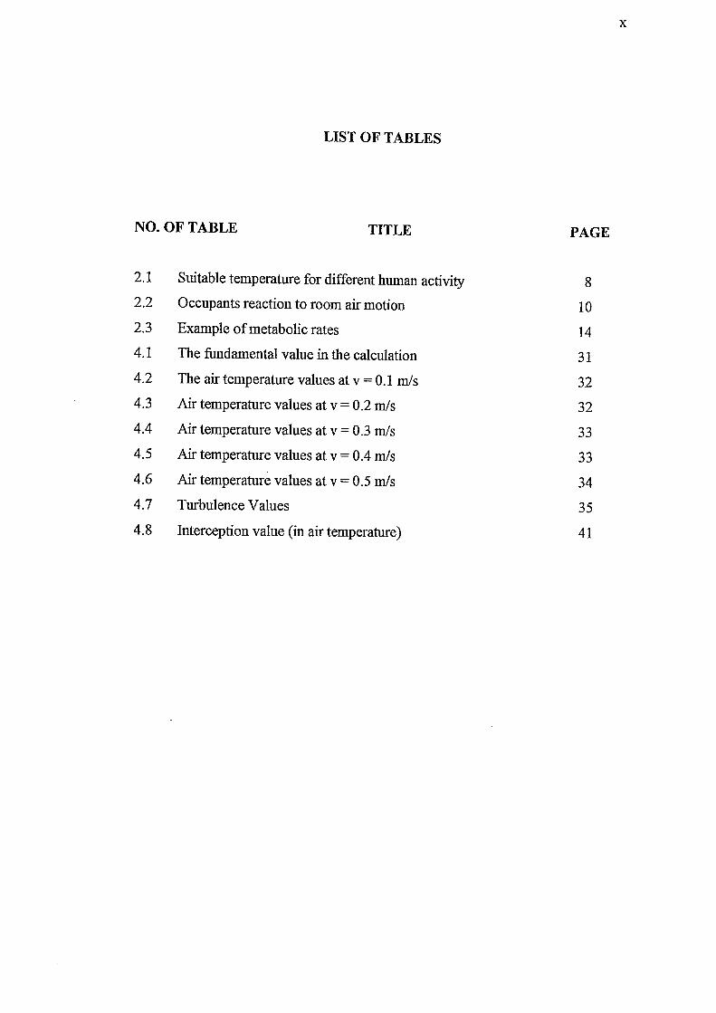
2.1 Suitable temperature for different human activity 8 2.2 Occupants reaction to room air motion 10 2.3 Example of metabolic rates 14 4.1 The fundamental value in the calculation 31 4.2 The air temperature values at v = 0.1 mls 32 4.3 Air temperature values at v = 0.2 mls 32 4.4 Air temperature values at v = 0.3 mls 33 4.5 Air temperature values at v = 0.4 mls 33 4.6 Air temperature values at v = 0.5 mls 34 4.7 Turbulence Values 35 4.8 Interception value (in air temperature) 41
XI
LIST OF FIGURES
NO. OF FIGURE TITLE PAGE
1.1 The relationship between PMV and PPD 3 1.2 Recent air conditioning system 5 1.3 The air conditioning system control knob. Users tend to
misuse it - thus produce an unhealthy environment and
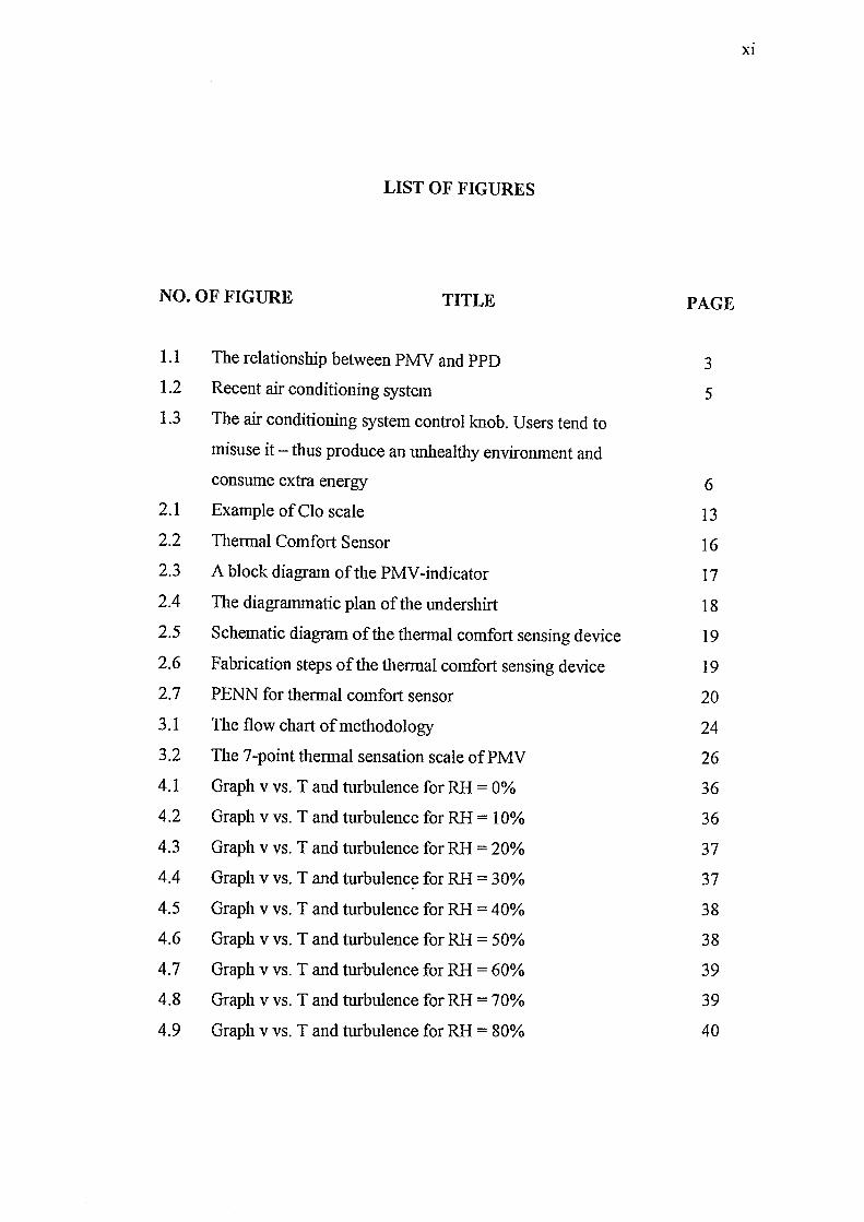
consume extra energy 6 2.1 Example of Clo scale 13 2.2 Thermal Comfort Sensor 16 2.3 A block diagram of the PMV -indicator 17 2.4 The diagrammatic plan of the undershirt 18 2.5 Schematic diagram of the thermal comfort sensing device 19 2.6 Fabrication steps of the thermal comfort sensing device 19 2.7 PENN for thermal comfort sensor 20 3.1 The flow chart of methodology 24 3.2 The 7 -point thennal sensation scale of PMV 26 4.1 Graph v vs. T and turbulence for RH = 0% 36 4.2 Graph v vs. T and turbulence for RH = 10% 36 4.3 Graph v vs. T and turbulence for RH = 20% 37 4.4 Graph v vs. T and turbulence for RH = 30% 37
4.5 Graph v vs. T and turbulence for RH = 40% 38
4.6 Graph v vs. T and turbulence for RH = 50% 38
4.7 Graph v vs. T and turbulence for RH = 60% 39
4.8 Graph v vs. T and turbulence for RH = 70% 39
4.9 Graph v vs. T and turbulence for RH = 80% 40
xu
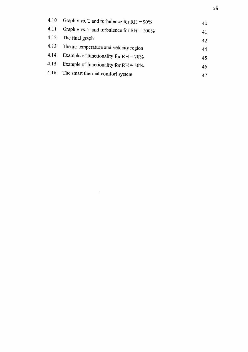
4.10 Graph v vs. T and turbulence for RH = 90% 40 4.11 Graph v vs. T and turbulence for RH = 100% 41 4.12 The final graph 42 4.13 The air temperature and velocity region 44 4.14 Example of functionality for RH = 70% 45 4.15 Example of functionality for RH = 50% 46 4.16 The smart thermal comfort system 47
Xlll
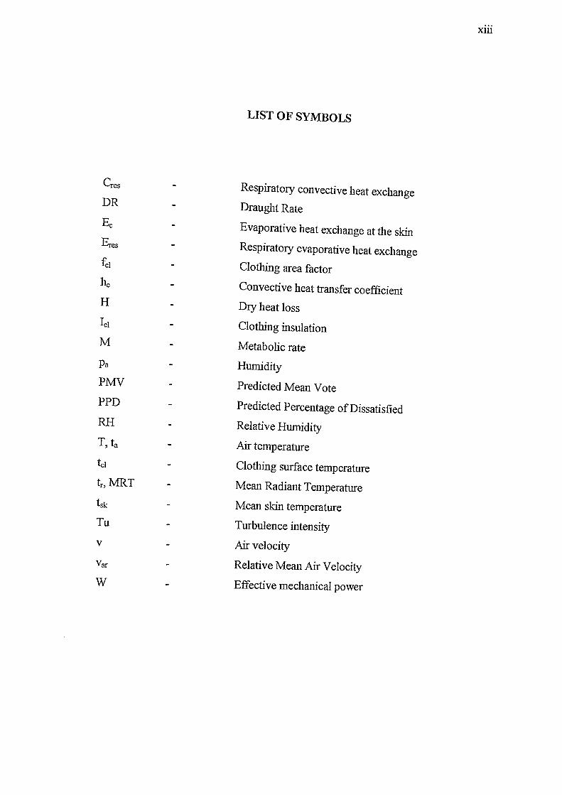
LIST OF SYMBOLS
Cres Respiratory convective heat exchange DR Draught Rate Ec Evaporative heat exchange at the skin Eres Respiratory evaporative heat exchange £;;1 Clothing area factor l1c Convective heat transfer coefficient H Dry heat loss leI Clothing insulation M Metabolic rate Pa Humidity PMV Predicted Mean Vote PPD Predicted Percentage of Dissatisfied RH Relative Humidity T, ta Air temperature tel Clothing surface temperature tr , MRT Mean Radiant Temperature tsk Mean skin temperature Tu Turbulence intensity v Air velocity Var Relative Mean Air Velocity W Effective mechanical power
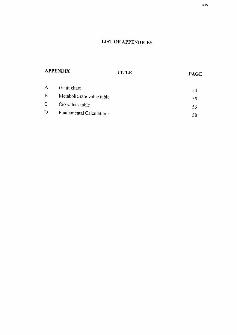
LIST OF APPENDICES
APPENDIX
A
B
C
D
Gantt chart
Metabolic rate value table
Clo values table
Fundamental Calculations
TITLE PAGE
54
55
56
58
XlV
1
CHAPTER I
INTRODUCTION
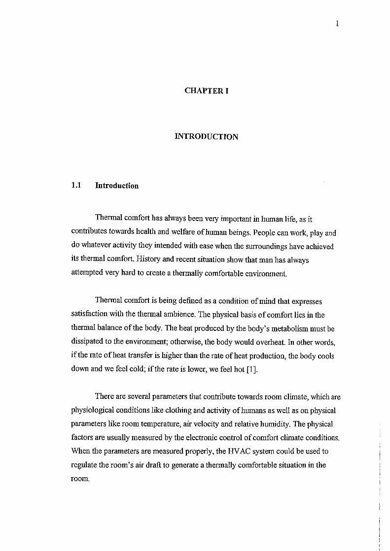
1.1 Introduction
Thennal comfort has always been very important in human life, as it
contributes towards health and welfare of human beings. People can work, play and
do whatever activity they intended with ease when the surroundings have achieved
its thennal comfort. History and recent situation show that man has always
attempted very hard to create a thennally comfortable environment.
Thennal comfort is being defined as a condition of mind that expresses
satisfaction with the thennal ambience. The physical basis of comfort lies in the
thennal balance of the body. The heat produced by the body's metabolism must be
dissipated to the environment; otherwise, the body would overheat. In other words,
if the rate of heat transfer is higher than the rate of heat production, the body cools
down and we feel cold; if the rate is lower, we feel hot [1].
There are several parameters that contribute towards room climate, which are
physiological conditions like clothing and activity of humans as well as on physical
parameters like room temperature, air velocity and relative humidity. The physical
factors are usually measured by the electronic control of comfort climate conditions.
When the parameters are measured properly, the HV AC system could be used to
regulate the room's air draft to generate a thennally comfortable situation in the
room.
2
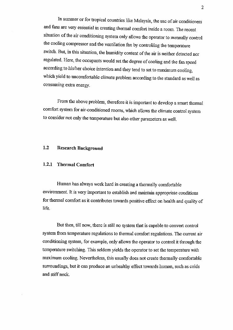
In summer or for tropical countries like Malaysia, the use of air conditioners
and fans are very ess'ential in creating thennal comfort inside a room. The recent
situation of the air conditioning system only allows the operator to manually control
the cooling compressor and the ventilation fan by controlling the temperature
switch. But, in this situation, the humidity content of the air is neither detected nor
regulated. Here, the occupants would set the degree of cooling and the fan speed
according to hislher choice intention and they tend to set to maximum cooling,
which yield to uncomfortable climate problem according to the standard as well as consuming extra energy.
From the above problem, therefore it is important to develop a smart thermal
comfort system for air-conditioned rooms, which allows the climate control system
to consider not only the temperature but also other parameters as well.
1.2 Research Background
1.2.1 Thermal Comfort
Human has always work hard in creating a thermally comfortable
environment. It is very important to establish and maintain appropriate conditions
for thermal comfort as it contributes towards positive effect on health and quality of life.
But then, till now, there is still no system that is capable to convert control
system from temperature regulations to thennal comfort regulations. The current air
conditioning system, for example, only allows the operator to control it through the
temperature switching. This seldom yields the operator to set the temperature with
maximum cooling. Nevertheless, this usually does not create thermally comfortable
surroundings, but it can produce an unhealthy effect towards human, such as colds
and stiff neck.
In a thermal comfort measurement, the system monitors on six variables _
four physical parameters and two physiological conditions - like air temperature,
relative humidity, air velocity, mean radiant temperature, clothing insulation and
human's level of activity. All the physical parameters are expected to be measured
and calculated using electronic devices, such as sensor.
3
One of the methods to determine thennal comfort, in fact is going to be used
in this study, is through the Predictive Mean Vote (PMV) index. The PMV-index
predicts the mean value of the subjective ratings of a group of people in a given environment [2].
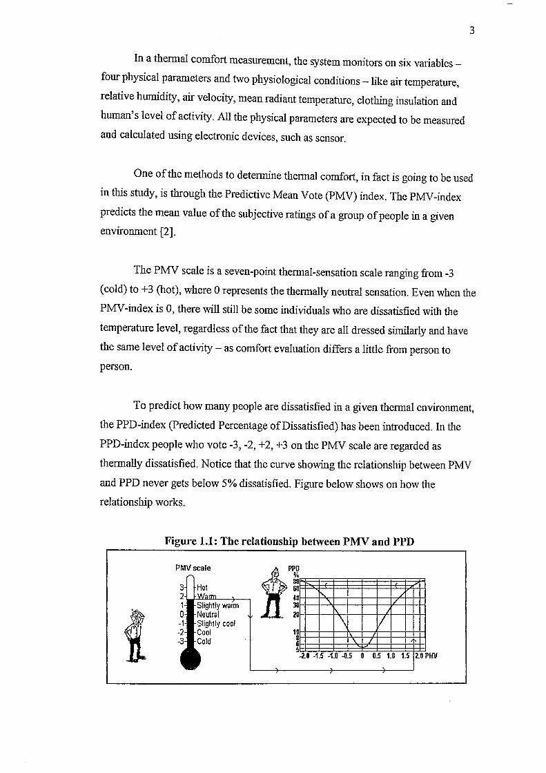
The PMV scale is a seven-point thennal-sensation scale ranging from-3
(cold) to +3 (hot), where ° represents the thermally neutral sensation. Even when the
PMV-index is 0, there will still be some individuals who are dissatisfied with the
temperature level, regardless of the fact that they are all dressed similarly and have
the same level of activity - as comfort evaluation differs a little from person to
person.
To predict how many people are dissatisfied in a given thermal environment,
the PPD-index (Predicted Percentage of Dissatisfied) has been introduced. In the
PPD-index people who vote -3, -2, +2, +3 on the PMV scale are regarded as
thermally dissatisfied. Notice that the curve showing the relationship between PMV
and PPD never gets below 5% dissatisfied. Figure below shows on how the
relationship works.
Figure 1.1: The relationship between PMV and PPD
PMVscale
.... :::illahtlV warm
cool
1.3 Problem Statement
In the present type of air conditioning systems the room's occupants are
allowed to control the system as they needed. Thus, as they feel hot and
uncomfortable with the room's climate, they tend to control the system into
maximum cooling. This yields to uncomfortable climate - too cold environment
would bring diseases such as cold, fever and stiff neck - as well as energy
consuming. Actually, the cooling method used by the system can be replaced by
blowing for better consumption of energy, since it allows the creation of thermally
comfortable environment through higher air velocity and higher air temperature
compared to before (as air temperature controls the air conditioning's compressor and air velocity controls the fan).
Most of the commercial system and sensor to measure thermal comfort
available in the market at the moment is constructed by a macroscopic system,
which is not suitable to be implemented. Therefore, by using MEMS technology, it
is possible to build a system to measure the thermal comfort in the room.
Microsystem is being preferred due to:
• High accuracy and sensitivity
• Capable to facilitate measurement of air velocity
• Lower power consumption
4
Figure below summarize the operation of the present type of air conditioning
system. The macrosensor part would obtain user's value of air temperature and fan
speed. It then will control the compressor and fan to meet the user's demand.
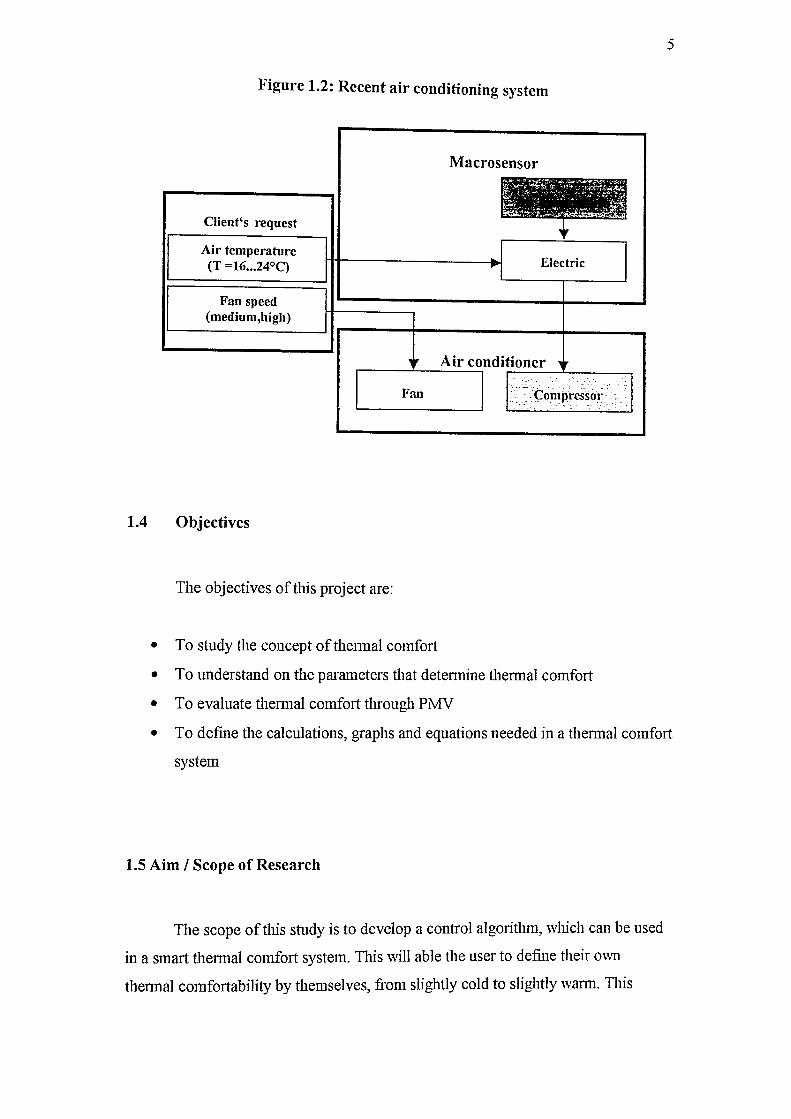
Figure 1.2: Recent air conditioning system
Client's request
Air temperatur'e (T =16 .•. 24°C)
Fan speed (medium,high)
Macrosensor
Electric
Air conditioner r-----~----~ r-----~----~
Fan I I<:O,"p~so..1
1.4 Objectives
The objectives of this project are:
• To study the concept ofthennal comfort
• To understand on the parameters that detennine thennal comfort
• To evaluate thennal comfort through PMV
5
• To define the calculations, graphs and equations needed in a thennal comfort
system
1.5 Aim I Scope of Research
The scope of tlns study is to develop a control algorithm, which can be used
in a smart thermal comfort system. TIus will able the user to define their own
thennal comfortability by themselves, from slightly cold to slightly wann. This
system would also provides with advantages -lower energy consumption at lower
cost and able to prevent any uncomfortable feelings towards operators.
6
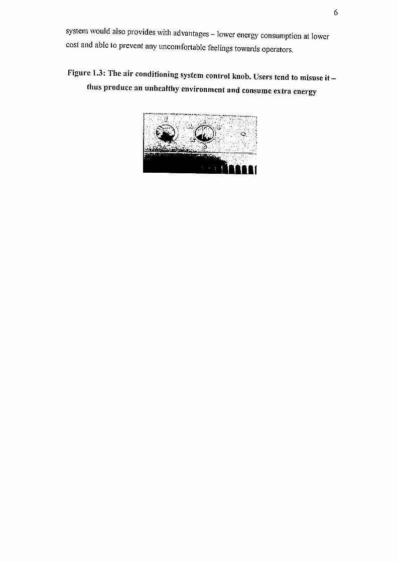
Figure 1.3: The air conditioning system control knob. Users tend to misuse it-
thus produce an unhealthy environment and consume extra energy
:l;. I' .... ~ "'~ "," t~ • ~ • r - -,'. " '",,-~," '. ;( , III